EP0897786B1 - Procédé de régulation d'une machine de moulage par injection de matières plastiques - Google Patents
Procédé de régulation d'une machine de moulage par injection de matières plastiques Download PDFInfo
- Publication number
- EP0897786B1 EP0897786B1 EP98810777A EP98810777A EP0897786B1 EP 0897786 B1 EP0897786 B1 EP 0897786B1 EP 98810777 A EP98810777 A EP 98810777A EP 98810777 A EP98810777 A EP 98810777A EP 0897786 B1 EP0897786 B1 EP 0897786B1
- Authority
- EP
- European Patent Office
- Prior art keywords
- pressure
- curve
- control
- injection
- cavity
- Prior art date
- Legal status (The legal status is an assumption and is not a legal conclusion. Google has not performed a legal analysis and makes no representation as to the accuracy of the status listed.)
- Expired - Lifetime
Links
Images


Classifications
-
- G—PHYSICS
- G05—CONTROLLING; REGULATING
- G05B—CONTROL OR REGULATING SYSTEMS IN GENERAL; FUNCTIONAL ELEMENTS OF SUCH SYSTEMS; MONITORING OR TESTING ARRANGEMENTS FOR SUCH SYSTEMS OR ELEMENTS
- G05B13/00—Adaptive control systems, i.e. systems automatically adjusting themselves to have a performance which is optimum according to some preassigned criterion
- G05B13/02—Adaptive control systems, i.e. systems automatically adjusting themselves to have a performance which is optimum according to some preassigned criterion electric
- G05B13/0205—Adaptive control systems, i.e. systems automatically adjusting themselves to have a performance which is optimum according to some preassigned criterion electric not using a model or a simulator of the controlled system
- G05B13/024—Adaptive control systems, i.e. systems automatically adjusting themselves to have a performance which is optimum according to some preassigned criterion electric not using a model or a simulator of the controlled system in which a parameter or coefficient is automatically adjusted to optimise the performance
-
- B—PERFORMING OPERATIONS; TRANSPORTING
- B29—WORKING OF PLASTICS; WORKING OF SUBSTANCES IN A PLASTIC STATE IN GENERAL
- B29C—SHAPING OR JOINING OF PLASTICS; SHAPING OF MATERIAL IN A PLASTIC STATE, NOT OTHERWISE PROVIDED FOR; AFTER-TREATMENT OF THE SHAPED PRODUCTS, e.g. REPAIRING
- B29C45/00—Injection moulding, i.e. forcing the required volume of moulding material through a nozzle into a closed mould; Apparatus therefor
- B29C45/17—Component parts, details or accessories; Auxiliary operations
- B29C45/76—Measuring, controlling or regulating
- B29C45/77—Measuring, controlling or regulating of velocity or pressure of moulding material
- B29C2045/776—Measuring, controlling or regulating of velocity or pressure of moulding material determining the switchover point to the holding pressure
-
- B—PERFORMING OPERATIONS; TRANSPORTING
- B29—WORKING OF PLASTICS; WORKING OF SUBSTANCES IN A PLASTIC STATE IN GENERAL
- B29C—SHAPING OR JOINING OF PLASTICS; SHAPING OF MATERIAL IN A PLASTIC STATE, NOT OTHERWISE PROVIDED FOR; AFTER-TREATMENT OF THE SHAPED PRODUCTS, e.g. REPAIRING
- B29C2945/00—Indexing scheme relating to injection moulding, i.e. forcing the required volume of moulding material through a nozzle into a closed mould
- B29C2945/76—Measuring, controlling or regulating
- B29C2945/76003—Measured parameter
- B29C2945/76006—Pressure
-
- B—PERFORMING OPERATIONS; TRANSPORTING
- B29—WORKING OF PLASTICS; WORKING OF SUBSTANCES IN A PLASTIC STATE IN GENERAL
- B29C—SHAPING OR JOINING OF PLASTICS; SHAPING OF MATERIAL IN A PLASTIC STATE, NOT OTHERWISE PROVIDED FOR; AFTER-TREATMENT OF THE SHAPED PRODUCTS, e.g. REPAIRING
- B29C2945/00—Indexing scheme relating to injection moulding, i.e. forcing the required volume of moulding material through a nozzle into a closed mould
- B29C2945/76—Measuring, controlling or regulating
- B29C2945/76177—Location of measurement
- B29C2945/76254—Mould
- B29C2945/76257—Mould cavity
-
- B—PERFORMING OPERATIONS; TRANSPORTING
- B29—WORKING OF PLASTICS; WORKING OF SUBSTANCES IN A PLASTIC STATE IN GENERAL
- B29C—SHAPING OR JOINING OF PLASTICS; SHAPING OF MATERIAL IN A PLASTIC STATE, NOT OTHERWISE PROVIDED FOR; AFTER-TREATMENT OF THE SHAPED PRODUCTS, e.g. REPAIRING
- B29C2945/00—Indexing scheme relating to injection moulding, i.e. forcing the required volume of moulding material through a nozzle into a closed mould
- B29C2945/76—Measuring, controlling or regulating
- B29C2945/76344—Phase or stage of measurement
- B29C2945/76384—Holding, dwelling
-
- B—PERFORMING OPERATIONS; TRANSPORTING
- B29—WORKING OF PLASTICS; WORKING OF SUBSTANCES IN A PLASTIC STATE IN GENERAL
- B29C—SHAPING OR JOINING OF PLASTICS; SHAPING OF MATERIAL IN A PLASTIC STATE, NOT OTHERWISE PROVIDED FOR; AFTER-TREATMENT OF THE SHAPED PRODUCTS, e.g. REPAIRING
- B29C2945/00—Indexing scheme relating to injection moulding, i.e. forcing the required volume of moulding material through a nozzle into a closed mould
- B29C2945/76—Measuring, controlling or regulating
- B29C2945/76494—Controlled parameter
- B29C2945/76531—Temperature
-
- B—PERFORMING OPERATIONS; TRANSPORTING
- B29—WORKING OF PLASTICS; WORKING OF SUBSTANCES IN A PLASTIC STATE IN GENERAL
- B29C—SHAPING OR JOINING OF PLASTICS; SHAPING OF MATERIAL IN A PLASTIC STATE, NOT OTHERWISE PROVIDED FOR; AFTER-TREATMENT OF THE SHAPED PRODUCTS, e.g. REPAIRING
- B29C2945/00—Indexing scheme relating to injection moulding, i.e. forcing the required volume of moulding material through a nozzle into a closed mould
- B29C2945/76—Measuring, controlling or regulating
- B29C2945/76494—Controlled parameter
- B29C2945/76551—Time
- B29C2945/76561—Time duration
-
- B—PERFORMING OPERATIONS; TRANSPORTING
- B29—WORKING OF PLASTICS; WORKING OF SUBSTANCES IN A PLASTIC STATE IN GENERAL
- B29C—SHAPING OR JOINING OF PLASTICS; SHAPING OF MATERIAL IN A PLASTIC STATE, NOT OTHERWISE PROVIDED FOR; AFTER-TREATMENT OF THE SHAPED PRODUCTS, e.g. REPAIRING
- B29C2945/00—Indexing scheme relating to injection moulding, i.e. forcing the required volume of moulding material through a nozzle into a closed mould
- B29C2945/76—Measuring, controlling or regulating
- B29C2945/76494—Controlled parameter
- B29C2945/76595—Velocity
-
- B—PERFORMING OPERATIONS; TRANSPORTING
- B29—WORKING OF PLASTICS; WORKING OF SUBSTANCES IN A PLASTIC STATE IN GENERAL
- B29C—SHAPING OR JOINING OF PLASTICS; SHAPING OF MATERIAL IN A PLASTIC STATE, NOT OTHERWISE PROVIDED FOR; AFTER-TREATMENT OF THE SHAPED PRODUCTS, e.g. REPAIRING
- B29C2945/00—Indexing scheme relating to injection moulding, i.e. forcing the required volume of moulding material through a nozzle into a closed mould
- B29C2945/76—Measuring, controlling or regulating
- B29C2945/76655—Location of control
- B29C2945/76658—Injection unit
-
- B—PERFORMING OPERATIONS; TRANSPORTING
- B29—WORKING OF PLASTICS; WORKING OF SUBSTANCES IN A PLASTIC STATE IN GENERAL
- B29C—SHAPING OR JOINING OF PLASTICS; SHAPING OF MATERIAL IN A PLASTIC STATE, NOT OTHERWISE PROVIDED FOR; AFTER-TREATMENT OF THE SHAPED PRODUCTS, e.g. REPAIRING
- B29C2945/00—Indexing scheme relating to injection moulding, i.e. forcing the required volume of moulding material through a nozzle into a closed mould
- B29C2945/76—Measuring, controlling or regulating
- B29C2945/76655—Location of control
- B29C2945/76732—Mould
-
- B—PERFORMING OPERATIONS; TRANSPORTING
- B29—WORKING OF PLASTICS; WORKING OF SUBSTANCES IN A PLASTIC STATE IN GENERAL
- B29C—SHAPING OR JOINING OF PLASTICS; SHAPING OF MATERIAL IN A PLASTIC STATE, NOT OTHERWISE PROVIDED FOR; AFTER-TREATMENT OF THE SHAPED PRODUCTS, e.g. REPAIRING
- B29C2945/00—Indexing scheme relating to injection moulding, i.e. forcing the required volume of moulding material through a nozzle into a closed mould
- B29C2945/76—Measuring, controlling or regulating
- B29C2945/76822—Phase or stage of control
- B29C2945/76862—Holding, dwelling
-
- B—PERFORMING OPERATIONS; TRANSPORTING
- B29—WORKING OF PLASTICS; WORKING OF SUBSTANCES IN A PLASTIC STATE IN GENERAL
- B29C—SHAPING OR JOINING OF PLASTICS; SHAPING OF MATERIAL IN A PLASTIC STATE, NOT OTHERWISE PROVIDED FOR; AFTER-TREATMENT OF THE SHAPED PRODUCTS, e.g. REPAIRING
- B29C2945/00—Indexing scheme relating to injection moulding, i.e. forcing the required volume of moulding material through a nozzle into a closed mould
- B29C2945/76—Measuring, controlling or regulating
- B29C2945/76822—Phase or stage of control
- B29C2945/76876—Switch-over
-
- B—PERFORMING OPERATIONS; TRANSPORTING
- B29—WORKING OF PLASTICS; WORKING OF SUBSTANCES IN A PLASTIC STATE IN GENERAL
- B29C—SHAPING OR JOINING OF PLASTICS; SHAPING OF MATERIAL IN A PLASTIC STATE, NOT OTHERWISE PROVIDED FOR; AFTER-TREATMENT OF THE SHAPED PRODUCTS, e.g. REPAIRING
- B29C2945/00—Indexing scheme relating to injection moulding, i.e. forcing the required volume of moulding material through a nozzle into a closed mould
- B29C2945/76—Measuring, controlling or regulating
- B29C2945/76929—Controlling method
- B29C2945/76979—Using a neural network
Definitions
- the invention relates to a method for controlling an injection molding plant for plastics according to the preamble of the appended claim 1.
- a method for controlling an injection molding plant for plastics is known from EP-A-0 707 936.
- the injection speed is controlled during each shot so that the pressure acting on the screw of the injector pressure follows each one recorded in the production of a good reference curve (see Plastverarbeiter 48/1 (1997), p 22:23 and references given there). Since the control takes place in real time, so the control unit must react very quickly, the effort required to implement the method in a generic injection molding is considerable, in particular high demands are placed on the computing power and storage capacity of the control unit, the signals directly from the monitored pressure waveform generated to control the injector. In addition, the regulation is possible only by means of a close involvement of the machine dynamics, so that it can be used practically only in the injection molding plant for which it was developed. A transfer to other systems is not possible without extensive and lengthy adjustments.
- the invention is therefore based on the object to provide a generic method, which is feasible by means of a relatively simple design evaluation and easily adapted to different injection molding equipment.
- the injection molding plant shown schematically in FIG. 1 has a heatable mold 1 with a cavity 2. This is connected via a sprue opening 3 with an injection device 4, which is controlled by a control unit 5, which also holds the mold temperature within a tolerance band by a predetermined desired target temperature.
- the injection device 4 comprises a screw 6 in a cylinder 7 with a funnel 8, e.g. hydraulic drive 9 for the screw 6 and a position monitor 10 for monitoring the position and speed of the same.
- Inputs of an evaluation unit 11 are arranged with the position monitoring device 10 and one located inside the cavity 2, e.g.
- the evaluation unit 11 is assigned a switching point detection unit 13 with which it exchanges data.
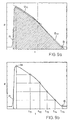
- the embodiment of the cavity 2 shown only very schematically in FIG. 1 can be better seen from FIG. It is a cavity for the production of a standard test rod, as for verification the influence of process parameters in injection molding often be used.
- the sprue opening 3 is arranged, at which a supply line connecting the cavity 2 with the injection device 4 (FIG. 1) opens.
- the pressure sensor 12 is arranged laterally on the wall of the cavity 2. He is thus at the same time at a point at which the cavity 2 transversely to the direction of flow of the plastic melt has maximum cross-section.
- the position of the pressure sensor 12 close to the sprue is preferred since it is thus already reached by the melt at the beginning of the filling phase and delivers meaningful values from then on, ie also for the course of the filling phase.
- Tests and measurements on a standard test rod manufactured on the system can be used to derive generally valid statements about the quality of parts that can be achieved on the system and with the control system used.
- the inventive method is therefore explained below using the example of the preparation of such a standard test rod.
- the method is primarily described when using amorphous plastic. When using semi-crystalline plastic is largely the same procedure. Significant deviations will be noted below.
- the basic procedure in the production of an injection molded part is the following:
- the cylinder 7 is filled via the hopper 8 with plastic granules, while the screw 6 is rotated by the drive device 9 in rotation and retracted to its normal position at the rear end of the cylinder 7.
- the screw 6 is rotated by the drive device 9 in rotation and retracted to its normal position at the rear end of the cylinder 7.
- the screw 6 is pushed by the drive 9 to the front and the melt injected through the gate 3 into the cavity 2.
- the force exerted by the drive 9 on the screw 6 due to the output signal of the position monitoring For example, regulated so that the screw propulsion speed as a function of the screw position follows a predetermined profile.
- position values can be fixed values or even linear ramps with fixed gradients for the screw propulsion speed.
- the simple case of a single fixed speed is possible.
- the course of the screw propulsion speed can also be regulated in a more or less complex manner.
- the evaluation unit 11 derives after each shot from the recorded by means of the pressure sensor 12 with a sampling frequency of, for example, 1 000 Hz pressure curve for the various control parameters in each case from a rating.
- a control factor for the injection speed, the holding pressure level, the holding pressure time and the mold temperature or, more precisely, the desired mold temperature, after which the mold temperature is controlled are preferably used as control parameters.
- the control factor of the injection speed affects the same, for example, by the speed profile, the course of which otherwise otherwise specified is multiplied by the same. Of course, given only a fixed rate of injection, this naturally results in using the injection rate itself as the control parameter.
- the Umschaltticianerkennung as it takes place in the Umschalt Vietnamese pet, can basically be done in any way. For example, it is carried out according to the method described in EP-A-0 707 936, which has proven to be very reliable.
- a reference curve is included in the rating. It corresponds to a pressure curve that has been measured and stored in the production of a good part, ie a part that meets the respective quality requirements.
- the production of the good part can be done under manual adjustment of the parameters, for example in the context of trial runs.
- a reference curve is recorded and, possibly after smoothing, evaluated, ie those quantities derived from it and stored in the evaluation unit, which are repeatedly required in series production in the determination of the reference variables.
- the neural networks are trained on the basis of experimentally determined data.
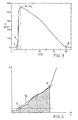
- FIG. 3 A pressure profile, which is obtained in the production of a good part and also used as reference curve, is shown in FIG. 3 (pressure p as a function of time t).
- the switching point P is also drawn and also in the determination of the guide variables important pressure maximum M, which of course in the case of Figure 3 coincides with the maximum pressure of the reference curve M 0 .
- the times injection start A and pressure drop B which can be defined, for example, by the increase in pressure above 5 bar or its drop below this limit.
- the scores are preferably normalized to lie between -1 and +1, being zero if the control parameter is set exactly right, while negative values indicate too low and positive values are indicative of an over-set control parameter.
- the value range of the evaluation can, for example, be divided into intervals and, if the evaluation of the last shot is at a certain interval, a specific correction factor can be derived from this circumstance. It is also possible to check the evaluation of the shot preceding the last shot to see whether it has a deviation of the same sign and only if a need is found and if a correction is carried out if both deviations have the same sign.
- the correction is preferably limited to at most one control parameter. This can e.g. the one whose rating deviates furthest from zero.
- the results for other control parameters can also be used in other ways for the decision as to whether a particular control parameter is changed or if there is a need for readjustment.
- the evaluation of the injection speed is included in the derivative of that for the head, because too high an injection speed also affects the part of the pressure curve, which is otherwise determined essentially by the head pressure.
- Nachregelungs site for the slow-reacting desired shape temperature is, for example, only confirmed if no Nachregelungs site was found at injection speed, holding pressure and holding pressure.
- the injection speed mainly influences the pressure curve during the filling phase. Too high injection speed causes a steep increase in this range, while too low injection speed results in a delayed and slow increase.
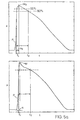
- the evaluation for the injection speed or for a control factor thereof is therefore derived (FIG. 4) from the pressure curve and the reference curve between the start of injection A and the switching point P.
- a first reference variable is determined, for example, by integrating the pressure profile over this section (FIG. 4, hatched area) and being divided by the corresponding variable derived from the reference profile.
- the regression line g e (FIG. 4) is laid by the pressure profile in said section according to the method of minimum quadratic deviation, and its slope is divided by the corresponding variable derived from the reference profile.
- the command values are fed to the two input neurons of a neural network, which derives therefrom an evaluation for the injection speed or its control factor.
- the determination of whether there is a need for further adjustment and, where appropriate, the decision on the size of the correction factor shall be made according to the nature and magnitude of the deviation from the last valuation of zero, taking into account the valuations of one to three further pre-emptive shots.
- the pressure head influences the pressure curve around the maximum pressure M, which is usually reached shortly after the switching point P. Too high a pressure level leads to an excessive pressure maximum in the cavity 2, which can cause stresses in the injection molded part and in the worst case, an opening or deformation of the mold 1. Too low pressure level leads to a too small maximum pressure and too rapid pressure drop, which may result in poor surface quality on the injection molded part.
- the evaluation for the injection speed is generally taken into account in addition to the pressure curve in the vicinity of the maximum pressure.
- the determination of the reference quantities is made on the basis of e.g. by averaging over some points of the smoothed current pressure curve and the smoothed reference curve.
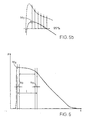
- the reference variables are determined such that an averaging of the pressure profile over a pressure maximum M 0 of the reference curve containing or adjacent region results.
- the reference curve is shown above, including the here characterized by a slightly too large Nachruckière current pressure curve.
- a second reference variable is determined by integrating the current pressure profile over a time interval (t1, t2) which is determined by the pressure being at least 90% of the maximum pressure M 0 in the reference curve; the integral is again divided by the corresponding quantity derived from the reference curve, ie the integral of the reference curve over the same time interval.
- Fig. 5b determined six other reference values by measuring the time interval between the pressure maximum M 0 of the reference waveform and the time that has dropped the same pressure on 95% to here is divided into 5 equal subintervals and at the location of Maximum pressure M 0 and formed at the end points of said sub-intervals respectively, the difference between the pressure according to the current pressure curve and according to the reference curve and divided by the maximum pressure M 0 of the reference curve becomes.
- the nine command values, along with the injection rate score, are again fed to nine neural network input neurons, which generates a rating for the peak head.
- a new evaluation is derived in a fine evaluation, for which only the six normalized pressure differences (FIG. 5b) and the maximum pressure M according to the current pressure profile, divided by the pressure maximum M 0 of the reference profile , to be used as reference quantities. This corresponds to a less pronounced averaging and causes greater sensitivity.
- the leaders are fed to the seven input neurons of another neural network, which derive a new rating from it.
- a provisional interval is first determined (FIG. 6) whose starting point lies in the maximum pressure M o of the reference curve and whose end point is determined by a bend in the reference curve, which was found with methods described below in connection with the determination of the reference variables for the hold-time becomes.
- the only reference variable in this case is determined as the function value of the parabola on the current pressure curve at the beginning of the remaining interval, divided by the corresponding variable derived from the reference curve. It becomes a neural network with in this case two liners fed, which derives therefrom a rating for the head pressure.
- the hold time affects the falling part of the pressure curve. If the holding time is too short, the pressure drops abruptly, which is reflected in a significant bend in the pressure curve. The too early pressure drop can have sink marks on the injection molded part result. Too long a hold-up time has no effect on the part quality of amorphous plastic, but extends the cycle time beyond the required level and degrades the output. For semicrystalline plastic, it may also have a minor effect on the morphology of the parts. A change in the holding pressure time is preferably carried out only under the condition that no Nachregelungs site has been found for the injection speed and the head pressure, because due to the influence of these parameters on the pressure curve otherwise a reliable assessment of the holding pressure is hardly possible.
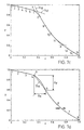
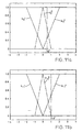
- FIG. 7a shows a pressure curve which corresponds to a clearly too short holding time.
- the maximum normal distance to the pressure curve is determined and finally the secant is recorded, where this maximum distance is greatest.
- the corresponding point of the pressure curve is identified as the approximate position of the desired bend.
- a shorter interval which is symmetrical about said point - the length can be eg 1/5 - is scanned with a shorter secant - time length eg 1/15 - after the secant with the maximum of the maximum distance, whereby the shorter secant in steps of eg 1/45 is shifted.
- the exact position is now determined analogous to finding the approximate position of the buck.
- an interval of length 2 * 1/15 symmetrical about the position of the crease is determined, and the time and pressure difference over the same are each normalized to 1 (FIG. 7b). Then the first half of the interval lying in front of the kink K in FIG. 4 and the second half in FIG. 5 are subdivided among each equidistant subintervals. At all division points 1-8 lying within the interval, the normal distance to the secant a is then determined. The normal distances form eight reference variables.
- the further steps are based on, for example, 1/15 extended interval and also normalized time and pressure difference in each case to 1.
- the part lying in front of the kink K, which occupies one third of the total length, is divided (FIG. 7c) into 6 equal subintervals, the remaining part in 8 also having equal subintervals, so that divisional points 1-15 are present with the boundary points.
- a total of seven parabolas are laid by successive triples of respective successive dividing points which overlap each of the triples at one point (FIG. 7c shows the parabolas p t2 through points 3,4,5 and p t5 through points 9, 10, 11).
- the twenty-two leaders are now fed to the input neurons of a two-lobe neural network, which in turn derives the corresponding score.
- the above described rough score gives a rating which is below a certain threshold or a kink K is identified, which is temporally offset from the kink K 0 of the reference curve by a difference ⁇ , so the holding pressure, for example, by a fixed or about a step function of the difference ⁇ dependent amount shortened. If, on the other hand, a kink is identified that lies ahead of that of the reference curve, then the hold-up time, eg also by a fixed amount or the difference ⁇ -dependent amount, is extended.
- the mold temperature also influences especially the falling part of the pressure curve after the maximum pressure M.
- To high mold temperature leads to a flat drop, possibly with a slightly concave section. It extends the cycle time and accordingly reduces the output.
- the other control parameters, especially holding pressure and holding pressure affect the falling part of the pressure curve and the mold temperature is very sluggish, a change is usually only useful if these control parameters are set correctly. Therefore, changes are made only under the condition that in all other control parameters, in particular the above no Nachregelungs supply was found.
- the reference quantities are fed to the input neurons of a neural network with nine input neurons and an intermediate layer, which derives from them a rating for the molding temperature. Based on the same, it is determined whether a Nachregelungs site exists and optionally set a correction factor for the desired shape temperature.
- the derivation of the evaluations can also be carried out using methods other than those described, for example by a purely logical-numerical method instead of involving neural networks, or mixed processing can take place.
- the input quantities for the neural networks are generated by numerical manipulations from the reference variables or also the evaluations from the output variables, eg the sensitivity can be set by multiplying the reference variables by a constant factor.
- the assessments to determine whether there is any need for a follow-up and, where appropriate, to determine the correction factor, there are many possibilities whose suitability may need to be verified and confirmed in a given case using the results of trial runs.
- a profile can be specified for the ice spraying speed, which profile is multiplied by a determined control factor.
- the profile may be normalized in some way, e.g., B. the maximum value can always be 1, so that the actual maximum of the ice injection speed corresponds to the control factor.
- the profile can also result from a regulation.
- the ice injection speed is adjusted so that the pressure curve in the filling phase corresponds as far as possible to a single straight line.
- the flow front spreads evenly, the cavity 2 (Fig. 2) is filled in accordance with evenly and tensions and distortion in the finished injection molded part, which otherwise often result due to uneven, leading to strong shearing leading flow conditions are avoided.
- test shot is made with a fixed sample profile.
- sample profile used at the beginning is a constant, ie an ice-spraying speed is fixed.
- the resulting pressure curve may, depending on the shape of the cavity 2, sometimes take different forms depending on the properties of the plastic melt used.
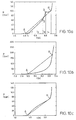
- FIGS. 10a-c Three typical pressure profiles recorded with constant ice injection speed are shown in FIGS. 10a-c.
- marked kinks occur in the course of the pressure and the sections lying between them deviate only slightly from a rectilinear course.
- the filling phase can therefore be subdivided directly into subintervals, in the example four subintervals I 1 ,..., I 4 , wherein the inner division points 1-3 correspond to the kinks. This subdivision is usually recorded for production.
- the pressure curve should as far as possible correspond to a single straight line drawn from the start of injection A to the switching point P. Deviations from this line, as e.g. may be caused by changing properties of the melt, must be registered and corrected by appropriate changes.
- the controlled variables used are preferably the absolute values of the velocity profile in the individual subintervals.
- a straight line is drawn, for example, after each shot through the pressure curve in each sub-interval.
- the control also has to take into account the machine dynamics. For example, a very fine subdivision of the filling phase into sub-intervals with a corresponding subdivision of the profile is not meaningful if the drive 9 (FIG. 1) of the one injection-speed spraying device 4 can not even follow the predetermined changes in the injection speed.
- FIG. 10b Especially if the cross-section of the cavity 2 (FIG. 2) decreases with increasing distance from the gate 3, a strongly concave pressure profile can result with a constant sample profile (FIG. 10b).
- pressure curves of the type discussed above as they are removed from Fig. 10a, it can be comparatively easily distinguished by the fact that the area between the pressure curve and the injection beginning A and the switching point P connecting secant is strongly negative (sections where the pressure curve below the secant lies in the bill with a negative sign).
- hardly any kinks in the interior of the filling phase, depending on the method used, usually at most one) can be determined and between any kinks, the pressure curve is not nearly linear.
- one of the methods described above may be used to detect a kink, e.g. by determining the maximum distance of the pressure curve from a straight line connecting beginning A and end P of the filling phase.
- the regulation of the profile for the injection speed is independent of the regulation of the other control parameters according to the pressure curve.
Claims (7)
- Procédé pour la régulation d'une machine de moulage par injection, dans laquelle des bains de matière synthétique sont injectés dans une ou plusieurs cavités par un dispositif d'injection (4) contrôlable, la pression intérieure d'outil (p) étant mesurée et contrôlée dans au moins une des cavités (2), caractérisé en ce que, après une charge d'injection, sur la base d'une comparaison de la courbe mesurée de pression intérieure d'outil avec une courbe théorique de pression intérieure connue, au moins l'un des paramètres de régulation vitesse d'injection, hauteur de maintien en pression, temps de maintien en pression et/ou température d'outil, est adapté au moins pour la charge d'injection suivante, un temps de réaction suffisant étant garanti pour la régulation avant chaque charge d'injection suivante.
- Procédé selon la revendication 1, caractérisé en ce qu'une variation d'un paramètre de régulation n'intervient que si, dans le cas de deux ou plus de deux contrôles consécutifs du paramètre correspondant, au moins deux dépassements de valeurs seuils prédéfinies du paramètre de régulation apparaissent.
- Procédé selon la revendication 1 ou 2, caractérisé en ce que la courbe théorique de pression intérieure d'outil correspond à une courbe mesurée antérieurement d'une pièce jugée bonne.
- Procédé selon la revendication 1 ou 2, caractérisé en ce que la pression intérieure d'outil (p) est mesurée en un endroit de la cavité (2) où sa section présente un maximum dans le sens transversal au sens d'écoulement du bain.
- Procédé selon l'une quelconque des revendications précédentes, caractérisé en ce que les paramètres de régulation sont réglés de telle sorte que la courbe mesurée est le plus possible identique à la courbe théorique.
- Procédé selon l'une quelconque des revendications précédentes, caractérisé en ce qu'un point d'inversion est déterminé, au moment duquel la cavité est complètement remplie.
- Procédé selon la revendication 6, caractérisé en ce que les paramètres de régulation sont réglés avant et après le point d'inversion.
Applications Claiming Priority (3)
| Application Number | Priority Date | Filing Date | Title |
|---|---|---|---|
| CH195797 | 1997-08-21 | ||
| CH1957/97 | 1997-08-21 | ||
| CH195797 | 1997-08-21 |
Publications (3)
| Publication Number | Publication Date |
|---|---|
| EP0897786A2 EP0897786A2 (fr) | 1999-02-24 |
| EP0897786A3 EP0897786A3 (fr) | 2002-03-20 |
| EP0897786B1 true EP0897786B1 (fr) | 2006-03-22 |
Family
ID=4222557
Family Applications (1)
| Application Number | Title | Priority Date | Filing Date |
|---|---|---|---|
| EP98810777A Expired - Lifetime EP0897786B1 (fr) | 1997-08-21 | 1998-08-13 | Procédé de régulation d'une machine de moulage par injection de matières plastiques |
Country Status (3)
| Country | Link |
|---|---|
| EP (1) | EP0897786B1 (fr) |
| AT (1) | ATE320904T1 (fr) |
| DE (1) | DE59813455D1 (fr) |
Cited By (4)
| Publication number | Priority date | Publication date | Assignee | Title |
|---|---|---|---|---|
| WO2009103147A1 (fr) * | 2008-02-19 | 2009-08-27 | Husky Injection Molding Systems Ltd. | Procédé de contrôle de la vitesse de remplissage dans un système de moulage |
| EP3546179A1 (fr) | 2018-03-28 | 2019-10-02 | Kistler Holding AG | Procédé de reproduction de la qualité de pièces moulées par injection lors du moulage par injection et installation de moulage par injection destinée à la mise en oeuvre du procédé |
| CN117245873A (zh) * | 2023-11-14 | 2023-12-19 | 广东美的制冷设备有限公司 | 注塑机初始工艺参数的确定方法、装置及注塑机 |
| EP2485881B2 (fr) † | 2009-10-05 | 2023-12-27 | Priamus System Technologies AG | Procédé pour réguler la fabrication d'un produit |
Families Citing this family (19)
| Publication number | Priority date | Publication date | Assignee | Title |
|---|---|---|---|---|
| US6682332B2 (en) | 2001-08-14 | 2004-01-27 | Alcoa Inc. | Dual isolated mode controller for injection molding machine |
| DE60109964T2 (de) * | 2001-08-14 | 2006-02-16 | Alcoa Inc. | Isolierte dualmodesteuerung für spritzgiessmaschine |
| DE10206073B8 (de) * | 2002-02-13 | 2006-09-14 | Tutech Innovation Gmbh | Vorrichtung zur Erfassung leitungsgeführter elektromagnetischer Pulse |
| AT7304U1 (de) * | 2003-09-10 | 2005-01-25 | Engel Austria Gmbh | Spritzgiessmaschine |
| DE102005016617B3 (de) * | 2005-04-12 | 2006-12-14 | Battenfeld Gmbh | Spritzgießverfahren |
| DE102006033421B3 (de) * | 2006-07-19 | 2007-10-11 | Mannesmann Plastics Machinery Gmbh | Sensor zur Verwendung bei einer Kunststoff verarbeitenden Maschine und Verfahren zum Betrieb eines solchen Sensors |
| EP2174769A1 (fr) * | 2008-10-07 | 2010-04-14 | Neo-plastic Dr. Doetsch Diespeck GmbH | Procédé de moulage par injection et installation correspondante |
| EP2488344A1 (fr) | 2009-10-12 | 2012-08-22 | Kistler Holding AG | Procédé de commande ou de réglage d'un processus d'injection |
| CN104290292A (zh) * | 2013-07-18 | 2015-01-21 | 昆山德安模具设计有限公司 | 一种智能注塑机 |
| AT514836B1 (de) * | 2013-09-30 | 2015-06-15 | Engel Austria Gmbh | Verfahren zur Bestimmung eines Siegelpunktes |
| CN107848175B (zh) * | 2015-07-22 | 2020-11-17 | 艾姆弗勒克斯有限公司 | 使用一个或多个外部传感器作为虚拟空腔传感器的注射模制方法 |
| US10836088B2 (en) | 2017-04-25 | 2020-11-17 | Kistler Holding, Ag | Method for reproducing injection molded parts of quality and injection molding unit for performing the method |
| EP3619022B1 (fr) | 2017-05-02 | 2021-10-13 | Imflux Inc. | Procédé de régulation de la vitesse ou de la force d'une pince dans un système de moulage à l'aide d'une ou de plusieurs jauges de contrainte |
| DE102017207586A1 (de) * | 2017-05-05 | 2018-11-08 | Arburg Gmbh + Co Kg | STEUERN UND REGELN DES DRUCKS EINER ZYKLISCH ARBEITENDEN SPRITZGIEßMASCHINE |
| DE102018108106B4 (de) * | 2018-04-05 | 2020-01-23 | Nolden Regelsysteme GmbH | Verfahren zum Regeln einer Temperatur einer Spritzgießmaschine und Regelsystem |
| JP6826086B2 (ja) | 2018-09-28 | 2021-02-03 | ファナック株式会社 | 状態判定装置及び状態判定方法 |
| DE102018126313A1 (de) | 2018-10-23 | 2020-04-23 | Kraussmaffei Technologies Gmbh | Verfahren zum Betreiben einer Spritzgießmaschine, insbesondere hinsichtlich verbesserter konstanter Werkzeugfüllung, sowie Spritzgießmaschine zur Durchführung des Verfahrens |
| CN111319206B (zh) * | 2018-12-13 | 2021-11-23 | 杭州电子科技大学 | 注塑成型系统中参数优化方法和装置 |
| DE102022206727A1 (de) | 2022-06-30 | 2024-01-04 | Baden-Württemberg Stiftung Ggmbh | Verfahren und Vorrichtung zur Prozessüberwachung während einer Herstellung eines Fertigteils aus einem heißvernetzenden Werkstoff in einem Urformverfahren |
Family Cites Families (6)
| Publication number | Priority date | Publication date | Assignee | Title |
|---|---|---|---|---|
| JPH0659675B2 (ja) * | 1987-01-30 | 1994-08-10 | 住友重機械工業株式会社 | 射出圧力設定方法及び射出成形機 |
| JP2608784B2 (ja) * | 1989-07-27 | 1997-05-14 | ファナック株式会社 | 電動式射出成形機 |
| JP2628266B2 (ja) * | 1993-03-31 | 1997-07-09 | 日精樹脂工業株式会社 | 射出成形機の速度制御方法及び装置 |
| US5425906A (en) * | 1993-09-21 | 1995-06-20 | Ube Industries, Inc. | Speed control method for injection molding machine |
| CH688441A5 (de) * | 1994-10-19 | 1997-09-30 | Kk Holding Ag | Verfahren zur Bestimmung des Umschaltpunktes bei der Herstellung eines Spritzgussteils. |
| DE19536566C1 (de) * | 1995-10-02 | 1997-02-06 | Arburg Gmbh & Co | Verfahren zur Regelung des Werkzeuginnendrucks an einer zyklisch arbeitenden Maschine |
-
1998
- 1998-08-13 AT AT98810777T patent/ATE320904T1/de active
- 1998-08-13 DE DE59813455T patent/DE59813455D1/de not_active Expired - Lifetime
- 1998-08-13 EP EP98810777A patent/EP0897786B1/fr not_active Expired - Lifetime
Cited By (7)
| Publication number | Priority date | Publication date | Assignee | Title |
|---|---|---|---|---|
| WO2009103147A1 (fr) * | 2008-02-19 | 2009-08-27 | Husky Injection Molding Systems Ltd. | Procédé de contrôle de la vitesse de remplissage dans un système de moulage |
| US7736555B2 (en) | 2008-02-19 | 2010-06-15 | Husky Injection Molding Systems Ltd. | Method for controlling fill speed in a molding system |
| CN101952103B (zh) * | 2008-02-19 | 2013-11-13 | 赫斯基注射器成型系统有限公司 | 用于控制模制系统中的填充速度的方法 |
| EP2485881B2 (fr) † | 2009-10-05 | 2023-12-27 | Priamus System Technologies AG | Procédé pour réguler la fabrication d'un produit |
| EP3546179A1 (fr) | 2018-03-28 | 2019-10-02 | Kistler Holding AG | Procédé de reproduction de la qualité de pièces moulées par injection lors du moulage par injection et installation de moulage par injection destinée à la mise en oeuvre du procédé |
| CN117245873A (zh) * | 2023-11-14 | 2023-12-19 | 广东美的制冷设备有限公司 | 注塑机初始工艺参数的确定方法、装置及注塑机 |
| CN117245873B (zh) * | 2023-11-14 | 2024-04-05 | 广东美的制冷设备有限公司 | 注塑机初始工艺参数的确定方法、装置及注塑机 |
Also Published As
| Publication number | Publication date |
|---|---|
| DE59813455D1 (de) | 2006-05-11 |
| EP0897786A3 (fr) | 2002-03-20 |
| EP0897786A2 (fr) | 1999-02-24 |
| ATE320904T1 (de) | 2006-04-15 |
Similar Documents
| Publication | Publication Date | Title |
|---|---|---|
| EP0897786B1 (fr) | Procédé de régulation d'une machine de moulage par injection de matières plastiques | |
| EP0909628B1 (fr) | Méthode et dispositif pour le réglage du chauffage du canal d'injection d'un moule à cavités multiples | |
| EP0062788B1 (fr) | Procédé et dispositif pour la fabrication en particulier d'ébauches creuses en matière thermoplastique | |
| EP0026828B1 (fr) | Dispositif pour influencer le poids d'un corps creux thermoplastique fabriqué selon le procédé d'extrusion-soufflage | |
| EP1761375A1 (fr) | Procede pour remplir au moins une cavite | |
| DE102015000219B4 (de) | Formklemmkrafteinstellvorrichtung und -Verfahren für eine Spritzgießmaschine | |
| EP0776752B1 (fr) | Procédé de moulage par soufflage de corps creux en matière thermoplastique | |
| EP2583811A1 (fr) | Procédé de quantification de basculements de procédés dans le cadre d'un processus d'injection d'une machine de moulage par injection | |
| EP0756219B1 (fr) | Procédé de surveillance des propriétés de produits et procédé de contrôle d'un procédé de fabrication | |
| EP1888316A1 (fr) | Procede de regulation du processus de moulage par injection d'une machine de moulage par injection | |
| EP0690778B1 (fr) | Procede et installation d'adaptation de la temperature d'outils de moulage pour matieres plastiques | |
| DE19801881C1 (de) | Verfahren zur Beurteilung von Spritzteilen | |
| EP0914925A1 (fr) | Procédé pour le conditionnement thermique de moules | |
| CH688441A5 (de) | Verfahren zur Bestimmung des Umschaltpunktes bei der Herstellung eines Spritzgussteils. | |
| EP0554286A1 (fr) | Procede et dispositif de production d'extrudats plats a section transversale annulaire. | |
| EP0784535B1 (fr) | Procede concu pour influer sur des valeurs de consigne de machines, et dispositif de mise en oeuvre dudit procede | |
| DE4434654C2 (de) | Verfahren zur Beeinflussung zyklisch ablaufender Prozesse | |
| WO2024083904A1 (fr) | Détermination de paramètres de processus | |
| EP2174769A1 (fr) | Procédé de moulage par injection et installation correspondante | |
| DE10222662B4 (de) | Verfahren zum Überwachen von Betriebsdaten einer Spritzgussmaschine | |
| DE102010002549B3 (de) | Spritzgussverfahren | |
| AT404076B (de) | Verfahren zum automatischen bestimmen des optimalen arbeitspunktes einer spritzgiessmaschine | |
| EP2616224B1 (fr) | Procédé de fabrication d'une pièce moulée en plastique | |
| EP3808531A2 (fr) | Procédé de conduite d'une buse de vanne à pointeau | |
| EP0868290B1 (fr) | Procede et dispositif de soudage a l'arc pour le soudage automatique de raccords pourvus d'un filament chauffant en spirale |
Legal Events
| Date | Code | Title | Description |
|---|---|---|---|
| PUAI | Public reference made under article 153(3) epc to a published international application that has entered the european phase |
Free format text: ORIGINAL CODE: 0009012 |
|
| AK | Designated contracting states |
Kind code of ref document: A2 Designated state(s): AT BE CH CY DE DK ES FI FR GB GR IE IT LI LU MC NL PT SE Kind code of ref document: A2 Designated state(s): AT CH DE FR IT LI |
|
| AX | Request for extension of the european patent |
Free format text: AL;LT;LV;MK;RO;SI |
|
| PUAL | Search report despatched |
Free format text: ORIGINAL CODE: 0009013 |
|
| AK | Designated contracting states |
Kind code of ref document: A3 Designated state(s): AT BE CH CY DE DK ES FI FR GB GR IE IT LI LU MC NL PT SE |
|
| AX | Request for extension of the european patent |
Free format text: AL;LT;LV;MK;RO;SI |
|
| 17P | Request for examination filed |
Effective date: 20020820 |
|
| AKX | Designation fees paid |
Free format text: AT CH DE FR IT LI |
|
| RAP1 | Party data changed (applicant data changed or rights of an application transferred) |
Owner name: KISTLER HOLDING AG |
|
| 17Q | First examination report despatched |
Effective date: 20031104 |
|
| GRAP | Despatch of communication of intention to grant a patent |
Free format text: ORIGINAL CODE: EPIDOSNIGR1 |
|
| GRAS | Grant fee paid |
Free format text: ORIGINAL CODE: EPIDOSNIGR3 |
|
| GRAA | (expected) grant |
Free format text: ORIGINAL CODE: 0009210 |
|
| AK | Designated contracting states |
Kind code of ref document: B1 Designated state(s): AT CH DE FR IT LI |
|
| REG | Reference to a national code |
Ref country code: CH Ref legal event code: EP |
|
| REF | Corresponds to: |
Ref document number: 59813455 Country of ref document: DE Date of ref document: 20060511 Kind code of ref document: P |
|
| ET | Fr: translation filed | ||
| PLBE | No opposition filed within time limit |
Free format text: ORIGINAL CODE: 0009261 |
|
| STAA | Information on the status of an ep patent application or granted ep patent |
Free format text: STATUS: NO OPPOSITION FILED WITHIN TIME LIMIT |
|
| 26N | No opposition filed |
Effective date: 20061227 |
|
| REG | Reference to a national code |
Ref country code: DE Ref legal event code: R039 Ref document number: 59813455 Country of ref document: DE Ref country code: DE Ref legal event code: R008 Ref document number: 59813455 Country of ref document: DE |
|
| REG | Reference to a national code |
Ref country code: DE Ref legal event code: R039 Ref document number: 59813455 Country of ref document: DE Effective date: 20140702 |
|
| REG | Reference to a national code |
Ref country code: DE Ref legal event code: R097 Ref document number: 59813455 Country of ref document: DE Ref country code: DE Ref legal event code: R040 Ref document number: 59813455 Country of ref document: DE |
|
| REG | Reference to a national code |
Ref country code: FR Ref legal event code: PLFP Year of fee payment: 19 |
|
| PGFP | Annual fee paid to national office [announced via postgrant information from national office to epo] |
Ref country code: CH Payment date: 20170216 Year of fee payment: 19 |
|
| REG | Reference to a national code |
Ref country code: FR Ref legal event code: PLFP Year of fee payment: 20 |
|
| PGFP | Annual fee paid to national office [announced via postgrant information from national office to epo] |
Ref country code: IT Payment date: 20170828 Year of fee payment: 20 Ref country code: FR Payment date: 20170822 Year of fee payment: 20 Ref country code: DE Payment date: 20170822 Year of fee payment: 20 |
|
| PGFP | Annual fee paid to national office [announced via postgrant information from national office to epo] |
Ref country code: AT Payment date: 20170822 Year of fee payment: 20 |
|
| REG | Reference to a national code |
Ref country code: CH Ref legal event code: PL |
|
| PG25 | Lapsed in a contracting state [announced via postgrant information from national office to epo] |
Ref country code: CH Free format text: LAPSE BECAUSE OF NON-PAYMENT OF DUE FEES Effective date: 20170831 Ref country code: LI Free format text: LAPSE BECAUSE OF NON-PAYMENT OF DUE FEES Effective date: 20170831 |
|
| REG | Reference to a national code |
Ref country code: DE Ref legal event code: R071 Ref document number: 59813455 Country of ref document: DE |
|
| REG | Reference to a national code |
Ref country code: AT Ref legal event code: MK07 Ref document number: 320904 Country of ref document: AT Kind code of ref document: T Effective date: 20180813 |