EP0027094B1 - Perfectionnements à la réalisation des boîtes à eau de générateur de vapeur - Google Patents
Perfectionnements à la réalisation des boîtes à eau de générateur de vapeur Download PDFInfo
- Publication number
- EP0027094B1 EP0027094B1 EP80401440A EP80401440A EP0027094B1 EP 0027094 B1 EP0027094 B1 EP 0027094B1 EP 80401440 A EP80401440 A EP 80401440A EP 80401440 A EP80401440 A EP 80401440A EP 0027094 B1 EP0027094 B1 EP 0027094B1
- Authority
- EP
- European Patent Office
- Prior art keywords
- waterbox
- partition plate
- hemispherical bottom
- plate
- groove
- Prior art date
- Legal status (The legal status is an assumption and is not a legal conclusion. Google has not performed a legal analysis and makes no representation as to the accuracy of the status listed.)
- Expired
Links
- XLYOFNOQVPJJNP-UHFFFAOYSA-N water Substances O XLYOFNOQVPJJNP-UHFFFAOYSA-N 0.000 title description 30
- 238000005192 partition Methods 0.000 claims description 35
- 239000012530 fluid Substances 0.000 description 7
- 238000003466 welding Methods 0.000 description 4
- 238000010926 purge Methods 0.000 description 3
- 238000004364 calculation method Methods 0.000 description 2
- 238000004519 manufacturing process Methods 0.000 description 2
- 239000000463 material Substances 0.000 description 2
- 239000010935 stainless steel Substances 0.000 description 2
- 229910001220 stainless steel Inorganic materials 0.000 description 2
- 229910000975 Carbon steel Inorganic materials 0.000 description 1
- 229910000831 Steel Inorganic materials 0.000 description 1
- 239000010962 carbon steel Substances 0.000 description 1
- 230000002452 interceptive effect Effects 0.000 description 1
- 238000012423 maintenance Methods 0.000 description 1
- 238000003032 molecular docking Methods 0.000 description 1
- 239000007787 solid Substances 0.000 description 1
- 239000010959 steel Substances 0.000 description 1
Images
Classifications
-
- F—MECHANICAL ENGINEERING; LIGHTING; HEATING; WEAPONS; BLASTING
- F22—STEAM GENERATION
- F22B—METHODS OF STEAM GENERATION; STEAM BOILERS
- F22B37/00—Component parts or details of steam boilers
- F22B37/02—Component parts or details of steam boilers applicable to more than one kind or type of steam boiler
- F22B37/22—Drums; Headers; Accessories therefor
-
- F—MECHANICAL ENGINEERING; LIGHTING; HEATING; WEAPONS; BLASTING
- F28—HEAT EXCHANGE IN GENERAL
- F28F—DETAILS OF HEAT-EXCHANGE AND HEAT-TRANSFER APPARATUS, OF GENERAL APPLICATION
- F28F9/00—Casings; Header boxes; Auxiliary supports for elements; Auxiliary members within casings
- F28F9/02—Header boxes; End plates
- F28F9/0202—Header boxes having their inner space divided by partitions
Definitions
- the invention relates to improvements in the production of water boxes for heat exchangers and in particular steam generators.
- the tubes of the primary circuit each form a U, the ends of which are fixed to a tubular plate provided with two series of orifices corresponding respectively to the inlet and the outlet of the primary fluid.
- the water box used for the supply and evacuation of the primary fluid is limited to its upper part by the tubular plate on which is fixed a hemispherical bottom separated into two parts by a semi-circular partition plate placed in a plane diametrical.
- the water box is thus divided into two chambers, supply and discharge respectively, and the hemispherical bottom is therefore provided with pipes for connection of the pipes, respectively for the arrival and exit of the primary fluid.
- the hemispherical bottom is also provided with manholes allowing access to each of the two chambers of the water box.
- the tubular plate is made of carbon steel coated with stainless steel
- the hemispherical bottom is of cast or forged steel
- the partition plate is made of solid stainless steel.
- the division of the hemispherical bottom into two chambers has another drawback. Indeed, it is sometimes necessary to access the interior of the water box for checking or maintenance operations. In this case, it is imperative to completely empty the water box of the contaminated water it contains. For this purpose, it is necessary, in each chamber to drill at the lower part of the hemispherical bottom of the bleed orifices which open into the inlet or outlet manifold of the primary fluid. But it is also necessary to drill other drain holes in the internal wall of the manhole so as to completely empty the space limited by the manhole closing plate and its cylindrical internal face placed in the thickness of the hemispherical background.
- the partition plate fits with play over its entire periphery in a circular groove and a diametrical groove formed respectively on the internal walls of the hemispherical bottom and of the tubular plate and the hemispherical bottom is crossed by at least a purge orifice opening at the lowest point of the circular groove for fitting the plate, said orifice being capable of communicating with the two chambers of the water box.
- the partition plate is mounted so as to be able to expand freely without interfering with the differential deformations of the tubular plate and of the hemispherical bottom. It has in fact been found that it is possible to keep the function of the separating plate of the water box into two chambers, by reducing by-pass to a minimum, without rigidly fixing it to the walls of the water box. In this way, the deformations of the water box are much easier to predict, and all the difficulties inherent in the production of welds are eliminated.
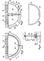
- the water box is shown in section limited to its upper part by the tubular plate 1 and to its lower part by the hemispherical bottom 2.
- the partition plate which has been removed in FIG. 2, divides the water box into two chambers 21 and 22, respectively for admission and discharge of the primary fluid. This circulates from one chamber to another in U-tubes not shown, the ends of which correspond to orifices 10 formed in the tube plate.
- the hemispherical bottom is provided, for each of the chambers 21 and 22, with a tube 23 to which the primary fluid circulation pipe is connected and with a manhole 24 allowing access to the interior of the chamber corresponding.
- FIG. 2 For the convenience of the drawing, there is shown in arbitrary positions, in FIG. 2, the supply tube 23 opening into the chamber 21 and a manhole 24 opening into the chamber 22.
- the partition plate is shown from the front in FIG. 3. It has, conventionally, the shape of a semicircle, and as can be seen in FIG. 4, it is preferably provided with a thinning over its whole periphery. In this way, it can penetrate with play in the grooves made on the tube plate 1 and on the hemispherical bottom 2.
- the upper groove 11 is constituted by a recess made in the underside of the tube plate, and in which engages the upper rectilinear edge 31 of the partition plate 3.
- the circular groove may consist of two parallel ribs 25 spaced from each other by a distance substantially equal to the thickness of the partition plate 3 and welded to the hemispherical bottom 2.
- the plate 3, penetrates with play between the two ribs 25.
- the partition plate 3 is made to rest directly on the ribs 25, for example by means of shims. support 32.
- the hemispherical bottom 2 is crossed at its lowest point, by an orifice 26 which opens in this way at the lowest point of the circular groove, between the two ribs 25.
- These are provided with passages 27 which allow the orifice 26 to communicate with the two chambers 21 and 22 of the water box.
- the partition plate 3 is independent of the walls limiting the water box. Indeed, it is simply supported on the hemispherical bottom 2 by the shims 32 and its upper part can slide freely inside the groove 11 of the tubular plate 1. Thus all the deformations and residual stresses due to the fixing by welding of the partition plate in the conventional embodiments. But in addition, the partition plate does not intervene in the deformations of the water box which can be calculated and therefore much easier to control.
- the fitting of the partition plate facilitates docking of the bottom on the tubular plate.
Landscapes
- Engineering & Computer Science (AREA)
- Physics & Mathematics (AREA)
- Thermal Sciences (AREA)
- Mechanical Engineering (AREA)
- General Engineering & Computer Science (AREA)
- Heat-Exchange Devices With Radiators And Conduit Assemblies (AREA)
- Sewage (AREA)
Applications Claiming Priority (2)
| Application Number | Priority Date | Filing Date | Title |
|---|---|---|---|
| FR7924986 | 1979-10-08 | ||
| FR7924986A FR2467355A1 (fr) | 1979-10-08 | 1979-10-08 | Perfectionnements a la realisation des boites a eau de generateur de vapeur |
Publications (2)
| Publication Number | Publication Date |
|---|---|
| EP0027094A1 EP0027094A1 (fr) | 1981-04-15 |
| EP0027094B1 true EP0027094B1 (fr) | 1982-04-07 |
Family
ID=9230438
Family Applications (1)
| Application Number | Title | Priority Date | Filing Date |
|---|---|---|---|
| EP80401440A Expired EP0027094B1 (fr) | 1979-10-08 | 1980-10-08 | Perfectionnements à la réalisation des boîtes à eau de générateur de vapeur |
Country Status (4)
| Country | Link |
|---|---|
| US (1) | US4422499A (show.php) |
| EP (1) | EP0027094B1 (show.php) |
| DE (1) | DE3060284D1 (show.php) |
| FR (1) | FR2467355A1 (show.php) |
Families Citing this family (14)
| Publication number | Priority date | Publication date | Assignee | Title |
|---|---|---|---|---|
| US4638768A (en) * | 1985-04-04 | 1987-01-27 | Westinghouse Electric Corp. | Steam generator tubesheet/channel head/centerstay assembly |
| FR2603373B1 (fr) * | 1986-09-02 | 1989-07-28 | Valeo | Element separateur pour la boite a eau d'un echangeur de chaleur |
| DE3924411A1 (de) * | 1989-07-24 | 1991-01-31 | Hoechst Ceram Tec Ag | Rippenrohrwaermetauscher |
| US5623763A (en) * | 1995-08-01 | 1997-04-29 | The Babcock & Wilcox Company | Method of replacing primary divider plate in a steam generator |
| JP3530660B2 (ja) * | 1995-12-14 | 2004-05-24 | サンデン株式会社 | 熱交換器のタンク構造 |
| FR2858683B1 (fr) * | 2003-08-07 | 2005-11-04 | Framatome Anp | Echangeur de chaleur et en particulier generateur de vapeur a fond convexe |
| KR100999961B1 (ko) | 2008-11-14 | 2010-12-09 | 주식회사 두원공조 | 2열의 튜브를 구비하는 열교환기의 헤더 |
| CN104246415A (zh) | 2011-12-06 | 2014-12-24 | 沙特阿拉伯石油公司 | 用于气冷热交换器的联管箱 |
| JP5840049B2 (ja) * | 2012-03-27 | 2016-01-06 | 三菱重工業株式会社 | 蒸気発生器製造方法 |
| CN104806997B (zh) * | 2015-05-25 | 2016-09-07 | 梁晓燕 | 一种蒸汽炉炉筒排气管 |
| US20170356674A1 (en) * | 2016-06-13 | 2017-12-14 | Laars Heating Systems Company | Water management header for a boiler or water heater |
| CN110917643A (zh) * | 2018-09-20 | 2020-03-27 | 深圳市引擎门科技有限公司 | 快速蒸发装置 |
| JP7579048B2 (ja) * | 2019-03-20 | 2024-11-07 | 三菱重工マリンマシナリ株式会社 | チューブ式熱交換器及びボイラ |
| CN115371296A (zh) * | 2021-05-21 | 2022-11-22 | 开利公司 | 用于冷凝器的水室结构、具有其的冷凝器及制冷系统 |
Family Cites Families (10)
| Publication number | Priority date | Publication date | Assignee | Title |
|---|---|---|---|---|
| DE7312164U (de) * | 1974-04-18 | Siemens Ag | Dampferzeuger für Kernkraftwerke | |
| DE502557C (de) * | 1930-07-16 | Wehrle Werk A G | Bodenkammer eines Waermeaustauschapparates | |
| US1831337A (en) * | 1928-01-27 | 1931-11-10 | O E Frank Heater & Engineering | Heat interchanger |
| US2237039A (en) * | 1937-12-14 | 1941-04-01 | Knapp Monarch Co | Fan structure |
| US2237029A (en) * | 1938-04-09 | 1941-04-01 | Westinghouse Electric & Mfg Co | High pressure head |
| FR1428131A (fr) * | 1964-02-19 | 1966-02-11 | Reactor Centrum Nederland | échangeur de chaleur composite et installation de réacteur équipée d'un échangeur de chaleur de ce type |
| US3635287A (en) * | 1970-03-02 | 1972-01-18 | Babcock & Wilcox Co | Once-through vapor generator |
| DE2612514B1 (de) * | 1976-03-24 | 1977-09-29 | Cenrus Ag | Rohrboden eines rohrbuendel-waermeaustauschers |
| DE2735450A1 (de) * | 1977-08-05 | 1979-02-15 | Kraftwerk Union Ag | Dampferzeuger fuer kernkraftwerke, insbesondere fuer druckwasserreaktoren |
| US4285396A (en) * | 1979-01-25 | 1981-08-25 | Wachter Associates, Inc. | Steam generator tube support system |
-
1979
- 1979-10-08 FR FR7924986A patent/FR2467355A1/fr active Granted
-
1980
- 1980-09-24 US US06/190,391 patent/US4422499A/en not_active Expired - Lifetime
- 1980-10-08 DE DE8080401440T patent/DE3060284D1/de not_active Expired
- 1980-10-08 EP EP80401440A patent/EP0027094B1/fr not_active Expired
Also Published As
| Publication number | Publication date |
|---|---|
| FR2467355B1 (show.php) | 1981-10-16 |
| EP0027094A1 (fr) | 1981-04-15 |
| DE3060284D1 (en) | 1982-05-19 |
| FR2467355A1 (fr) | 1981-04-17 |
| US4422499A (en) | 1983-12-27 |
Similar Documents
| Publication | Publication Date | Title |
|---|---|---|
| EP0027094B1 (fr) | Perfectionnements à la réalisation des boîtes à eau de générateur de vapeur | |
| EP0633427A1 (fr) | Echangeur de chaleur comportant un faisceau de tubes cintrés en U et des barres antivibratoires entre les parties cintrées des tubes | |
| EP0028189B1 (fr) | Chaudière nucléaire | |
| EP1902266B1 (fr) | Ensemble d'echange de chaleur, notamment pour reacteur nucleaire a haute temperature | |
| EP0477066A1 (fr) | Procédé de remplacement d'un tube d'un échangeur de chaleur à tubes droits et utilisation de ce procédé | |
| EP0057643B1 (fr) | Dispositif de protection de la plaque tubulaire à l'extrémité chaude d'un échangeur de chaleur vertical | |
| EP0012042B1 (fr) | Dispositif de supportage et de protection pour chaudières nucléaires | |
| EP0117191B1 (fr) | Générateur de vapeur pour un réacteur nucléaire refroidi par du métal liquide | |
| EP0607071B1 (fr) | Echangeur de chaleur dans lequel l'alimentation en fluide secondaire s'effectue en partie haute par un déversoir | |
| EP0173586B1 (fr) | Echangeur de chaleur comportant un faisceau de tubes disposé dans une enveloppe de faisceau cylindrique maintenue radialement à l'intérieur d'une enveloppe cylindrique externe | |
| FR2858845A1 (fr) | Echangeur de chaleur et procede de fabrication | |
| EP0091374B1 (fr) | Dispositif d'obturation de secours, en cas de fuite, d'un tube d'un générateur de vapeur | |
| EP0023177B1 (fr) | Chaudière nucléaire | |
| CA2478751C (fr) | Echangeur de chaleur et en particulier generateur de vapeur a fond convexe | |
| FR2665758A1 (fr) | Procede de bouchage d'un tube d'un echangeur de chaleur a tubes droits et utilisation de ce procede. | |
| EP0108690B1 (fr) | Echangeur de chaleur pour fluides à température élevée dont l'un des fluides entre et sort par la partie supérieure de l'échangeur | |
| EP0975919B1 (fr) | Corps de chauffe pour une chaudiere au fioul ou au gaz et modules pour la realisation d'un tel corps de chauffe | |
| EP0020264A1 (fr) | Echangeur de chaleur du type semi-modulaire pour réacteur nucléaire | |
| EP0206921B1 (fr) | Echangeur de chaleur à tubes en U coaxiaux à écoulement intermédiaire de gaz neutre et réacteur nucléaire à neutrons rapides comportant des échangeurs de ce type | |
| BE1007153A5 (fr) | Echangeur de chaleur a dispositif de maintien anti-sismique et de supportage anti-envol de l'enveloppe entourant le faisceau de tubes. | |
| FR3112189A1 (fr) | Système de réparation d’un tore d’eau alimentaire et méthode de réparation associée | |
| FR2471550A1 (fr) | Generateur de vapeur d'eau, particulierement pour centrales nucleaires, permettant un remplacement plus facile des pieces | |
| EP0061381B1 (fr) | Générateur de vapeur surchauffée | |
| FR2492078A1 (fr) | Condenseur basse temperature de grande puissance | |
| EP0216667B1 (fr) | Dispositif de retenue de liquide dans une canalisation sensiblement horizontale présentant une extrémité ouverte lorsque, le débit du liquide descend en-dessous d'un seuil donné |
Legal Events
| Date | Code | Title | Description |
|---|---|---|---|
| PUAI | Public reference made under article 153(3) epc to a published international application that has entered the european phase |
Free format text: ORIGINAL CODE: 0009012 |
|
| AK | Designated contracting states |
Designated state(s): BE DE IT |
|
| 17P | Request for examination filed |
Effective date: 19810417 |
|
| ITF | It: translation for a ep patent filed | ||
| GRAA | (expected) grant |
Free format text: ORIGINAL CODE: 0009210 |
|
| AK | Designated contracting states |
Designated state(s): BE DE IT |
|
| REF | Corresponds to: |
Ref document number: 3060284 Country of ref document: DE Date of ref document: 19820519 |
|
| ITTA | It: last paid annual fee | ||
| PGFP | Annual fee paid to national office [announced via postgrant information from national office to epo] |
Ref country code: BE Payment date: 19940929 Year of fee payment: 15 |
|
| PGFP | Annual fee paid to national office [announced via postgrant information from national office to epo] |
Ref country code: DE Payment date: 19941004 Year of fee payment: 15 |
|
| PG25 | Lapsed in a contracting state [announced via postgrant information from national office to epo] |
Ref country code: BE Effective date: 19951031 |
|
| BERE | Be: lapsed |
Owner name: FRAMATOME Effective date: 19951031 |
|
| PG25 | Lapsed in a contracting state [announced via postgrant information from national office to epo] |
Ref country code: DE Effective date: 19960801 |
|
| PLBE | No opposition filed within time limit |
Free format text: ORIGINAL CODE: 0009261 |
|
| STAA | Information on the status of an ep patent application or granted ep patent |
Free format text: STATUS: NO OPPOSITION FILED WITHIN TIME LIMIT |