EP0026891B1 - Einrichtung für den Vorschub eines Schweissdrahtes - Google Patents
Einrichtung für den Vorschub eines Schweissdrahtes Download PDFInfo
- Publication number
- EP0026891B1 EP0026891B1 EP80105864A EP80105864A EP0026891B1 EP 0026891 B1 EP0026891 B1 EP 0026891B1 EP 80105864 A EP80105864 A EP 80105864A EP 80105864 A EP80105864 A EP 80105864A EP 0026891 B1 EP0026891 B1 EP 0026891B1
- Authority
- EP
- European Patent Office
- Prior art keywords
- wire
- guide
- welding
- rollers
- gap
- Prior art date
- Legal status (The legal status is an assumption and is not a legal conclusion. Google has not performed a legal analysis and makes no representation as to the accuracy of the status listed.)
- Expired
Links
Images

Classifications
-
- B—PERFORMING OPERATIONS; TRANSPORTING
- B23—MACHINE TOOLS; METAL-WORKING NOT OTHERWISE PROVIDED FOR
- B23K—SOLDERING OR UNSOLDERING; WELDING; CLADDING OR PLATING BY SOLDERING OR WELDING; CUTTING BY APPLYING HEAT LOCALLY, e.g. FLAME CUTTING; WORKING BY LASER BEAM
- B23K9/00—Arc welding or cutting
- B23K9/12—Automatic feeding or moving of electrodes or work for spot or seam welding or cutting
- B23K9/133—Means for feeding electrodes, e.g. drums, rolls, motors
- B23K9/1336—Driving means
Definitions
- the invention relates to a device for feeding a welding wire, which is provided with a pair of axially parallel, in one plane mounted rollers for feeding the welding wire inserted between the rollers and perpendicular to the roller axes, and with a welding wire guide which has a tubular wire channel and which has a gap penetrating the wire channel in the roller plane, into which the rollers can be inserted up to the wire channel, the welding wire guide with its wire exit end being insertable into the opening of a connecting member of a welding wire conductor.
- a pipe section serves as the welding wire guide, the inner diameter of which is adapted to the welding wire diameter.
- these tube pieces are to be made with inner diameters, the production of which requires a great technological effort.
- the starting material for these wire guides is therefore expensive and must also be subjected to a machining shaping.
- DE-C-937906 discloses a welding wire guide in the area of the welding torch mouthpiece, which consists of two movable contact jaws secured against longitudinal movement.
- guide rails are simple and can be based on cheap starting material and can take place, for example, by non-cutting shaping, which is considerably more time-saving and cheaper than the machining shaping. It is therefore expedient to produce the guide rails from preferably cold-rolled steel strip, which is particularly suitable for non-cutting shaping.
- a feed roller unit 1 is mounted on a tripod 2.
- the feed roller unit 1 consists of a drive roller 3, which is driven by a motor mounted behind the stand 2 via a gear, not shown here, and a pressure roller 5, the axis 6 of which is mounted in a bracket 7.
- the bracket 7 with the pressure roller 5 is pivotable in the roller plane about a pin 8 which is fixed in the stand 2.
- a spring arm 9 is pivotable about a pin 10 attached to the bracket 7.
- a screw 11 is fastened to the front end of the spring arm and is inserted into a groove 12 of a flange 13 of the stand 2. The distance between the spring arm 9 and the flange 13 can be adjusted with the aid of nuts 14.
- a wire guide 15 for the welding wire is inserted between a nose 16 projecting from the stand and a junction box 17 for a welding cable, not shown here.
- the junction box is provided with a cylindrical guide sleeve 18 into which one end of the wire guide 15 is inserted.
- the cylindrical guide sleeve could, for example, also be attached in the head end of the welding cable that can be connected in the connection box 17.
- the junction box 17, which is not described in more detail here, is provided in a known manner with connections for welding current, protective gas and, if appropriate, for other media required for carrying out the welding process. These media are transferred to the welding socket in the junction box, which connects the feed roller unit 1 to a welding torch, for example a welding gun.
- the wire guide 15 consists of two identical guide rails 19, 20.
- a groove 21, 22 is pressed into each guide rail, which together form a wire channel 23 for the welding wire.
- Several connecting pins 24 are pressed into each guide rail and some holes 25 are punched out.
- the connecting pins 24 serve as rivets, which hold the two guide rails together after being pressed into the holes 25.
- a slot is also punched out in each guide rail. After assembly, these form a gap 26 in which the two rollers 3, 5 are inserted in order to advance the welding wire which is accessible in the gap 26 and is not shown here.
- the wire guide has two support edges 27, 28, which are supported against the guide sleeve 18 and the nose 16 and fix the wire guide in the axial direction.
- the front end of the guide rail is formed by pressing into lips 29, 30, into whose tube-shaped opening formed by the joining is inserted a bendable wire conductor 31 through which the welding wire (not shown here) is taken from a wire magazine, for example a coil; is fed to the feed device.
- the rear end 32 is dovetail-shaped, which facilitates the insertion of the wire guide 15 into the guide sleeve 18.
- the wire guide 15 If the wire guide 15 is to be attached in the feed device, the screw 11 of the spring arm 9 is pushed out of the groove 12 and the bracket 7 with the pressure roller 5 is turned upwards. In order to get past the nose 16, the wire guide must be inserted with its rear end 32 somewhat obliquely into the guide sleeve 18 until it rests on the guide sleeve 18 with the support edge 28. The oblique insertion is made possible by the dovetail-shaped end 32. Then the wire guide 15 is brought with the gap 26 over the roller 3 and at the same time aligned with the guide sleeve 18, so that the supporting edge 27 abuts the nose 16 and the wire guide is secured in the axial direction against displacement.
- the welding wire (not shown here) is fed through the wire conductor 31 and manually advanced through the gap 26. Now the pressure roller 5 is inserted into the gap 26 and the spring arm 9 clamped in the groove 12, whereby the pressure roller 5 is pressed against the wire and the roller 3.
- the contact pressure can be adjusted using the nuts 14 by changing the distance between the spring arm 9 and flange 13.
- the feed device is now ready for wire feed.
- the device enables the wire guides to be replaced very quickly, for example when changing to a different wire diameter or because of wear after a long period of operation.
Landscapes
- Engineering & Computer Science (AREA)
- Physics & Mathematics (AREA)
- Plasma & Fusion (AREA)
- Mechanical Engineering (AREA)
- Wire Processing (AREA)
- Arc Welding In General (AREA)
- Butt Welding And Welding Of Specific Article (AREA)
- Electrical Discharge Machining, Electrochemical Machining, And Combined Machining (AREA)
- Crystals, And After-Treatments Of Crystals (AREA)
- Wire Bonding (AREA)
- Treatment Of Steel In Its Molten State (AREA)
- Ropes Or Cables (AREA)
- Metal Extraction Processes (AREA)
- Lining Or Joining Of Plastics Or The Like (AREA)
- Guides For Winding Or Rewinding, Or Guides For Filamentary Materials (AREA)
Description
- Die Erfindung bezieht sich auf eine Einrichtung für den Vorschub eines Schweissdrahtes, die mit einem Paar achsparallelen, in einer Ebene angebrachten Rollen für den Vorschub des zwischen den Rollen und senkrecht zu den Rollenachsen eingeführten Schweissdrahtes und mit einer Schweissdrahtführung versehen ist, die einen rohrartigen Drahtkanal aufweist und die in der Rollenebene einen den Drahtkanal durchsetzenden Spalt besitzt, in den die Rollen bis zum Drahtkanal einführbar sind, wobei die Schweissdrahtführung mit ihrem Drahtaustrittsende in die Öffnung eines Anschlussgliedes eines Schweissdrahtleiters einführbar ist.
- Bei einer in der britischen Patentschrift GB-A-977 443 beschriebenen Einrichtung dieser Gattung dient als Schweissdrahtführung ein Rohrstück, dessen Innendurchmesser an den Schweissdrahtdurchmesser angepasst ist. Mit Rücksicht auf die kleinen Schweissdrahtdurchmesser von etwa 1 mm und noch weniger sind diese Rohrstücke mit Innendurchmessern auszuführen, deren Herstellung einen grossen technologischen Aufwand erfordert. Das Ausgangsmaterial für diese Drahtführungen ist daher teuer und muss zusätzlich noch einer spanabhebenden Formgebung unterworfen werden.
- Weiter ist durch die DE-C-937906 eine Schweissdrahtführung im Bereich des Schweissbrennermundstückes bekannt geworden, die aus zwei beweglichen, gegen Längsbewegung gesicherten Kontaktbacken besteht.
- Bei der Fabrikation grosser Serien ist es besonders wünschenswert, die Herstellungskosten jedes einzelnen Details so niedrig als möglich zu halten. Bereits geringfügige Kosteneinsparungen per Einheit bringen bei grossen Stückzahlen wesentliche wirtschaftliche Vorteile.
- Zur Lösung der Aufgabe wird die im Anspruch 1 angegebene Einrichtung vorgeschlagen. Weitere vorteilhafte Ausgestaltungen der Erfindung sind in den Unteransprüchen angegeben.
- Die Herstellung derartiger Führungsschienen ist einfach und kann von billigem Ausgangsmaterial ausgehen und beispielsweise durch spanlose Formgebung erfolgen, die wesentlich zeitsparender und billiger als die spanabhebende Formgebung ist. So ist es zweckmässig, die Führungsschienen aus vorzugsweise kaltgewalztem Bandstahl herzustellen, der sich für eine spanlose Formgebung besonders eignet.
- Die Erfindung wird nun nachfolgend im Zusammenhang mit dem in der Zeichnung dargestellten Ausführungsbeispiel näher erläutert.
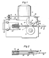
- Fig. 1 zeigt eine Vorschubeinrichtung für einen Schweissdraht.
- Fig. 2 zeigt ein Detail von Fig. 1 im Schnitt längs II-II.
- Fig. 3 zeigt in etwas grösserem Massstab eine Drahtführung für den Schweissdraht.
- Fig. 4 stellt teilweise im Schnitt eine Seitenansicht der Drahtführung dar.
- Fig. 5-8 zeigen verschiedene Schnitte durch die Drahtführung längs V-V, VI-VI, VII-VII und VIII-Vill der Fig. 3.
- Eine Vorschubrolleneinheit 1 ist auf einem Stativ 2 montiert. Die Vorschubrolleneinheit 1 besteht aus einer Antriebsrolle 3, die über ein hier nicht gezeigtes Getriebe von einem hinter dem Stativ 2 angebrachten Motor angetrieben wird, und einer Druckrolle 5, deren Achse 6 in einem Bügel 7 gelagert ist. Der Bügel 7 mit der Druckrolle 5 ist in der Rollenebene schwenkbar um einen Zapfen 8, der im Stativ 2 befestigt ist. Ein Federarm 9 ist schwenkbar um einen auf dem Bügel 7 angebrachten Zapfen 10. Am vorderen Ende des Federarms ist eine Schraube 11 befestigt, die in eine Nut 12 eines Flansches 13 des Statives 2 eingeschoben ist. Der Abstand zwischen dem Federarm 9 und dem Flansch 13 ist mit Hilfe von Muttern 14 einstellbar.
- Eine Drahtführung 15 für den Schweissdraht ist zwischen einer aus dem Stativ vorspringenden Nase 16 und einer Anschlussdose 17 für ein hier nicht dargestelltes Schweisskabel eingesetzt. Die Anschlussdose ist mit einer zylindrischen Führungshülse 18 versehen, in die das eine Ende der Drahtführung 15 eingeführt ist. Die zylindrische Führungshülse könnte jedoch beispielsweise auch im Kopfende des in der Anschlussdose 17 anschliessbaren Schweisskabels angebracht sein. Die Anschlussdose 17, die im übrigen hier nicht näher beschrieben ist, ist auf bekannte Weise mit Anschlüssen für Schweissstrom, Schutzgas und gegebenenfalls für andere für die Durchführung des Schweissverfahrens erforderlichen Medien versehen. Diese Medien werden in der Anschlussdose ins Schweisskabei übergeführt, das die Vorschubrolleneinheit 1 mit einem Schweissbrenner, beispielsweise einer Schweisspistole, verbindet.
- Die Drahtführung 15 besteht aus zwei identischen Führungsschienen 19, 20. In jeder Führungsschiene ist eine Rinne 21, 22 eingepresst, die zusammen einen Drahtkanal 23 für den Schweissdraht bilden. In jeder Führungsschiene sind einige Verbindungsstifte 24 eingepresst und einige Löcher 25 ausgestanzt. Beim Zusammenfügen der beiden Führungsschienen längs ihren Stossflächen werden die Verbindungsstifte 24 der einen in die entsprechenden Löcher der anderen Führungsschiene eingeführt. Die Verbindungsstifte 24 dienen als Nieten, die nach dem Einpressen in die Löcher 25 die beiden Führungsschienen zusammenhalten. In jeder Führungsschiene ist ausserdem ein Schlitz ausgestanzt. Diese bilden nach dem Zusammenfügen einen Spalt 26, in der die beiden Rollen 3, 5 eingeführt sind, um den im Spalt 26 zugänglichen, hier nicht dargestellten Schweissdraht vorzuschieben.
- In Fig. 1 und Fig. 2 sind die Verbindungsstifte 24 und Löcher 25 der Übersichtlichkeit halber nicht wiedergegeben.
- Die Drahtführung hat zwei Stützkanten 27, 28, die sich gegen die Führungshülse 18 und die Nase 16 abstützen und die Drahtführung in axialer Richtung fixieren. Das vordere Ende der Führungsschiene ist durch Pressen zu Lippen 29, 30 umgeformt, in deren durch das Zusammenfügen gebildete rohrförmige Öffnung ein biegbarer Drahtleiter 31 eingeführt ist, durch den der Schweissdraht (hier nicht dargestellt) von einem Drahtmagazin, beispielsweise einer Spule; der Vorschubeinrichtung zugeführt wird. Das rückwärtige Ende 32 ist schwalbenschwanzförmig gestaltet, wodurch das Einsetzen der Drahtführung 15 in die Führungshülse 18 erleichtert wird.
- Wenn die Drahtführung 15 in der Vorschubeinrichtung angebracht werden soll, wird die Schraube 11 des Federarms 9 aus der Nut 12 herausgeschoben und der Bügel 7 mit der Druckrolle 5 nach oben gedreht. Um an der Nase 16 vorbeizukommen, muss die Drahtführung mit ihrem rückwärtigen Ende 32 etwas schräg in die Führungshülse 18 eingeführt werden, bis sie mit der Stützkante 28 an der Führungshülse 18 anliegt. Das schräge Einführen wird durch das schwalbenschwanzförmige Ende 32 ermöglicht. Danach wird die Drahtführung 15 mit dem Spalt 26 über die Rolle 3 gebracht und gleichzeitig mit der Führungshülse 18 ausgerichtet, so dass die Stützkante 27 an der Nase 16 anliegt und die Drahtführung in axialer Richtung gegen Verschiebung gesichert ist.
- Der Schweissdraht (hier nicht dargestellt) wird durch den Drahtleiter 31 zugeführt, und durch den Spalt 26 manuell vorgeschoben. Nun wird die Druckrolle 5 in den Spalt 26 eingeführt und der Federarm 9 in der Nut 12 eingespannt, wodurch die Druckrolle 5 gegen den Draht und die Rolle 3 gepresst wird. Der Anpressdruck kann mit Hilfe der Muttern 14 durch Änderung des Abstandes zwischen Federarm 9 und Flansch 13 eingestellt werden. Die Vorschubeinrichtung ist damit für den Drahtvorschub betriebsbereit.
- Die Einrichtung ermöglicht einen sehr raschen Austausch der Drahtführungen, beispielsweise beim Übergang auf einen anderen Drahtdurchmesser oder wegen Verschleisses nach längerer Betriebszeit.
Claims (4)
Priority Applications (1)
| Application Number | Priority Date | Filing Date | Title |
|---|---|---|---|
| AT80105864T ATE5570T1 (de) | 1979-10-08 | 1980-09-27 | Einrichtung fuer den vorschub eines schweissdrahtes. |
Applications Claiming Priority (2)
| Application Number | Priority Date | Filing Date | Title |
|---|---|---|---|
| SE7908296A SE451806B (sv) | 1979-10-08 | 1979-10-08 | Anordning for frammatning av en svetstrad |
| SE7908296 | 1979-10-08 |
Publications (2)
| Publication Number | Publication Date |
|---|---|
| EP0026891A1 EP0026891A1 (de) | 1981-04-15 |
| EP0026891B1 true EP0026891B1 (de) | 1983-12-14 |
Family
ID=20338992
Family Applications (1)
| Application Number | Title | Priority Date | Filing Date |
|---|---|---|---|
| EP80105864A Expired EP0026891B1 (de) | 1979-10-08 | 1980-09-27 | Einrichtung für den Vorschub eines Schweissdrahtes |
Country Status (11)
| Country | Link |
|---|---|
| EP (1) | EP0026891B1 (de) |
| JP (1) | JPS5666381A (de) |
| AT (1) | ATE5570T1 (de) |
| AU (1) | AU540873B2 (de) |
| BR (1) | BR8006438A (de) |
| DE (1) | DE3065901D1 (de) |
| DK (1) | DK423980A (de) |
| FI (1) | FI69976C (de) |
| HU (1) | HU183229B (de) |
| SE (1) | SE451806B (de) |
| YU (1) | YU255780A (de) |
Families Citing this family (2)
| Publication number | Priority date | Publication date | Assignee | Title |
|---|---|---|---|---|
| FR2542719B1 (fr) * | 1983-03-16 | 1985-07-26 | Grenon Rene | Dispositif d'entrainement d'un fil rigide serre entre deux galets a gorge |
| CN106698084A (zh) * | 2015-11-12 | 2017-05-24 | 无锡威格斯电气有限公司 | 一种细导线导向装置 |
Citations (1)
| Publication number | Priority date | Publication date | Assignee | Title |
|---|---|---|---|---|
| GB977443A (en) * | 1962-10-29 | 1964-12-09 | Philips Electronic Associated | Improvements in and relating to apparatus for feeding wire |
Family Cites Families (8)
| Publication number | Priority date | Publication date | Assignee | Title |
|---|---|---|---|---|
| BE527794A (de) * | ||||
| US2179108A (en) * | 1937-06-12 | 1939-11-07 | Borg Warner | Nozzle for arc-welding machine |
| FR1097808A (fr) * | 1953-04-06 | 1955-07-11 | Union Carbide & Carbon Corp | Buse de guidage et d'amenée de courant pour un fil électrode de soudage |
| DE937906C (de) * | 1953-04-06 | 1956-01-19 | Union Carbide & Carbon Corp | Schweissstabfuehrung und Kontaktbacken bei Schweisskoepfen und -pistolen fuer die automatische Lichtbogenschweissung mit sich verbrauchender Metallelektrode |
| US2756310A (en) * | 1953-04-06 | 1956-07-24 | Union Carbide & Carbon Corp | Welding rod holder |
| GB752672A (en) * | 1953-04-06 | 1956-07-11 | Union Carbide & Carbon Corp | Welding rod guide and electric contact jaw assembly |
| GB931500A (en) * | 1961-02-07 | 1963-07-17 | Pulimax Aktiebolag | Welding electrode holder |
| DE1177266B (de) * | 1961-02-07 | 1964-09-03 | Pullmax Ab | Rohrfoermiges Schweissbrennermundstueck mit austauschbaren Fuehrungs- und Kontaktbacken |
-
1979
- 1979-10-08 SE SE7908296A patent/SE451806B/sv not_active IP Right Cessation
-
1980
- 1980-09-23 FI FI802990A patent/FI69976C/sv not_active IP Right Cessation
- 1980-09-27 DE DE8080105864T patent/DE3065901D1/de not_active Expired
- 1980-09-27 AT AT80105864T patent/ATE5570T1/de not_active IP Right Cessation
- 1980-09-27 EP EP80105864A patent/EP0026891B1/de not_active Expired
- 1980-10-06 JP JP13965280A patent/JPS5666381A/ja active Pending
- 1980-10-06 YU YU02557/80A patent/YU255780A/xx unknown
- 1980-10-07 HU HU802441A patent/HU183229B/hu unknown
- 1980-10-07 AU AU63033/80A patent/AU540873B2/en not_active Ceased
- 1980-10-07 BR BR8006438A patent/BR8006438A/pt unknown
- 1980-10-07 DK DK423980A patent/DK423980A/da not_active Application Discontinuation
Patent Citations (1)
| Publication number | Priority date | Publication date | Assignee | Title |
|---|---|---|---|---|
| GB977443A (en) * | 1962-10-29 | 1964-12-09 | Philips Electronic Associated | Improvements in and relating to apparatus for feeding wire |
Also Published As
| Publication number | Publication date |
|---|---|
| FI69976B (fi) | 1986-01-31 |
| YU255780A (en) | 1983-02-28 |
| ATE5570T1 (de) | 1983-12-15 |
| SE7908296L (sv) | 1981-04-09 |
| FI802990A7 (fi) | 1981-04-09 |
| BR8006438A (pt) | 1981-04-14 |
| AU6303380A (en) | 1981-04-16 |
| SE451806B (sv) | 1987-11-02 |
| FI69976C (fi) | 1986-09-12 |
| DK423980A (da) | 1981-04-09 |
| HU183229B (en) | 1984-04-28 |
| EP0026891A1 (de) | 1981-04-15 |
| JPS5666381A (en) | 1981-06-04 |
| DE3065901D1 (en) | 1984-01-19 |
| AU540873B2 (en) | 1984-12-06 |
Similar Documents
| Publication | Publication Date | Title |
|---|---|---|
| EP2202025A1 (de) | Verfahren und Vorrichtung zum Verbinden von Metallbändern durch Reibpunktschweissen | |
| DE3615706C2 (de) | ||
| DE10131461C1 (de) | Anlage zum Zusammenfügen und Längsschweißen von aus Blechen oder dergleichen gebogenen Rohren | |
| EP0413955A2 (de) | Vorrichtung zum Runden und Weiterfördern von Blechzuschnitten für Dosenzargen | |
| AT509066B1 (de) | Vorrichtung zum reibrührschweissen | |
| DE10223703A1 (de) | Bandverbindungsvorrichtung | |
| DE2650357A1 (de) | Verfahren und vorrichtung zur herstellung kreisfoermig gebogener werkstuecke aus einem geraden profilstrang, insbesondere von felgen fuer speichenraeder | |
| EP0335081A1 (de) | Vorrichtung zur Walzgutführung zwischen den Walzen eines Walzgerüstes | |
| DE2944666A1 (de) | Vorrichtung zum ablaengen und biegen der anschlussdraehte von elektrischen bauelementen | |
| DE2839407C2 (de) | Widerstandsschweißmaschine zum Nahtschweißen von überlappten Blechrändern | |
| DE2431790C2 (de) | Vorrichtung zum Kehlnahtschweißen von Längsgliedern an einer waagerechten Grundplatte einer Rahmenkonstruktion | |
| DE29719436U1 (de) | Schweißvorrichtung | |
| DE2502651A1 (de) | Richtmaschine | |
| EP0026891A1 (de) | Einrichtung für den Vorschub eines Schweissdrahtes | |
| DE2203913C2 (de) | Vorrichtung zum Ankuppen von Draht | |
| DE2738238C2 (de) | ||
| DE2918537C2 (de) | Vorrichtung zum Entgraten von widerstandsstumpfgeschweißten Rohren | |
| DE2537888C2 (de) | Vorrichtung zum Aneinanderschweißen von Bändern für Maschinen zum Herstellen von Schraubennahtrohren | |
| EP0313760A2 (de) | Vorrichtung zum Herstellen von Trägern für Bauzwecke und dergl. | |
| DE846838C (de) | Rohrschweissmaschine | |
| DE2241028C3 (de) | Vorrichtung zum Abschneiden des innenseftigen Längsgrats von SchweiBrohren | |
| AT407020B (de) | Antriebsvorrichtung für einen schweissdraht | |
| DE1949262C3 (de) | Vorrichtung zur Führung und zum Transport einer Schweiß- oder Bearbeitungsvorrichtung | |
| DE2718233A1 (de) | Verfahren und maschine zur herstellung von roehrenkondensatoren | |
| DE225897C (de) |
Legal Events
| Date | Code | Title | Description |
|---|---|---|---|
| PUAI | Public reference made under article 153(3) epc to a published international application that has entered the european phase |
Free format text: ORIGINAL CODE: 0009012 |
|
| AK | Designated contracting states |
Designated state(s): AT BE CH DE FR GB IT NL SE |
|
| ITCL | It: translation for ep claims filed |
Representative=s name: JACOBACCI CASETTA & PERANI S.P.A. |
|
| 17P | Request for examination filed |
Effective date: 19810908 |
|
| ITF | It: translation for a ep patent filed | ||
| GRAA | (expected) grant |
Free format text: ORIGINAL CODE: 0009210 |
|
| AK | Designated contracting states |
Designated state(s): AT BE CH DE FR GB IT LI NL SE |
|
| PG25 | Lapsed in a contracting state [announced via postgrant information from national office to epo] |
Ref country code: SE Effective date: 19831214 |
|
| REF | Corresponds to: |
Ref document number: 5570 Country of ref document: AT Date of ref document: 19831215 Kind code of ref document: T |
|
| REF | Corresponds to: |
Ref document number: 3065901 Country of ref document: DE Date of ref document: 19840119 |
|
| ET | Fr: translation filed | ||
| PGFP | Annual fee paid to national office [announced via postgrant information from national office to epo] |
Ref country code: DE Payment date: 19840831 Year of fee payment: 5 |
|
| PGFP | Annual fee paid to national office [announced via postgrant information from national office to epo] |
Ref country code: FR Payment date: 19840906 Year of fee payment: 5 |
|
| PG25 | Lapsed in a contracting state [announced via postgrant information from national office to epo] |
Ref country code: AT Effective date: 19840927 |
|
| PGFP | Annual fee paid to national office [announced via postgrant information from national office to epo] |
Ref country code: BE Payment date: 19840930 Year of fee payment: 5 |
|
| PLBE | No opposition filed within time limit |
Free format text: ORIGINAL CODE: 0009261 |
|
| STAA | Information on the status of an ep patent application or granted ep patent |
Free format text: STATUS: NO OPPOSITION FILED WITHIN TIME LIMIT |
|
| PGFP | Annual fee paid to national office [announced via postgrant information from national office to epo] |
Ref country code: CH Payment date: 19841026 Year of fee payment: 5 |
|
| 26N | No opposition filed | ||
| PGFP | Annual fee paid to national office [announced via postgrant information from national office to epo] |
Ref country code: NL Payment date: 19850930 Year of fee payment: 6 |
|
| PG25 | Lapsed in a contracting state [announced via postgrant information from national office to epo] |
Ref country code: LI Effective date: 19860930 Ref country code: CH Effective date: 19860930 Ref country code: BE Effective date: 19860930 |
|
| BERE | Be: lapsed |
Owner name: ESAB A.B. Effective date: 19860930 |
|
| PG25 | Lapsed in a contracting state [announced via postgrant information from national office to epo] |
Ref country code: NL Effective date: 19870401 |
|
| NLV4 | Nl: lapsed or anulled due to non-payment of the annual fee | ||
| PG25 | Lapsed in a contracting state [announced via postgrant information from national office to epo] |
Ref country code: FR Free format text: LAPSE BECAUSE OF NON-PAYMENT OF DUE FEES Effective date: 19870527 |
|
| REG | Reference to a national code |
Ref country code: CH Ref legal event code: PL |
|
| PG25 | Lapsed in a contracting state [announced via postgrant information from national office to epo] |
Ref country code: DE Effective date: 19870602 |
|
| GBPC | Gb: european patent ceased through non-payment of renewal fee | ||
| REG | Reference to a national code |
Ref country code: FR Ref legal event code: ST |
|
| PG25 | Lapsed in a contracting state [announced via postgrant information from national office to epo] |
Ref country code: GB Effective date: 19881118 |