EP0024765B1 - Appareil d'enregistrement ou de reproduction sur bande, à tête magnétique rotative - Google Patents
Appareil d'enregistrement ou de reproduction sur bande, à tête magnétique rotative Download PDFInfo
- Publication number
- EP0024765B1 EP0024765B1 EP80200780A EP80200780A EP0024765B1 EP 0024765 B1 EP0024765 B1 EP 0024765B1 EP 80200780 A EP80200780 A EP 80200780A EP 80200780 A EP80200780 A EP 80200780A EP 0024765 B1 EP0024765 B1 EP 0024765B1
- Authority
- EP
- European Patent Office
- Prior art keywords
- clamping
- head
- drum system
- drive spindle
- ring
- Prior art date
- Legal status (The legal status is an assumption and is not a legal conclusion. Google has not performed a legal analysis and makes no representation as to the accuracy of the status listed.)
- Expired
Links
Images


Classifications
-
- G—PHYSICS
- G11—INFORMATION STORAGE
- G11B—INFORMATION STORAGE BASED ON RELATIVE MOVEMENT BETWEEN RECORD CARRIER AND TRANSDUCER
- G11B5/00—Recording by magnetisation or demagnetisation of a record carrier; Reproducing by magnetic means; Record carriers therefor
- G11B5/48—Disposition or mounting of heads or head supports relative to record carriers ; arrangements of heads, e.g. for scanning the record carrier to increase the relative speed
- G11B5/52—Disposition or mounting of heads or head supports relative to record carriers ; arrangements of heads, e.g. for scanning the record carrier to increase the relative speed with simultaneous movement of head and record carrier, e.g. rotation of head
- G11B5/53—Disposition or mounting of heads on rotating support
Definitions
- the invention relates to a tape recording reproducing apparatus using a magnetic tape with oblique signal tracks and comprising: an at least partly cylindrical drive spindle having a free end and axis of rotation, a stationary guide drum, concentric with the said axis of rotation, for guiding a magnetic tape, a rotatable head-drum system, which is detachably secured to a cylindrical portion of the drive spindle so that it is situated with its first side near the free end of said spindle and remotely from said stationary guide drum and with its second side spaced from the stationary guide drum by a narrow gap, which rotatable head-drum system comprises one or more protruding magnetic heads near the said gap and is formed with a central bore for mounting on the drive spindle, as well as a centring device on the first side of the rotatable head-drum system for centring this system on the drive spindle, said centring device comprising a resiliently deformable wall portion which is fixedly connected to the first side of the rotatable head-drum system
- the head-drum system comprises a cylindrical head-drum which constitutes the rotary part of a drum unit for guiding the magnetic tape past the magnetic heads in a helical path.
- the drum unit also comprises a stationary drum which is coaxial with said rotary drum and is spaced therefrom by a narrow gap.
- On the stationary drum there is provided a helical guide edge for the magnetic tape, which edge extends over part of its circumference.
- the head-drum On its first side which is remote from the stationary drum the head-drum is provided with a clamping sleeve with a cylindrical outer surface, which constitutes the elastically deformable wall portion.
- a clamping ring Around said clamping sleeve a clamping ring is mounted, which is formed with a slot in its ring wall, so that the parts of the clamping ring which are spaced by the slot can be moved resiliently towards each other.
- a threaded bolt On the one side of the slot a threaded bolt is fitted into the clamping ring and extends with clearance through the clamping ring on the other side of the slot.
- Modern helical-scan video cassette recorders may employ slightly overlapping signal tracks having a width of approximately 40 microns and having a centre- to-centre spacing of the tracks of approximately 30 microns.
- the track length is approximately 100 mm.
- the tracks should be situated within narrow tolerances over the entire length, in particular because great value is attached to the possibility of playing back on one video recorder video programs recorded with another similar video recorder, without an appreciable lo.ss of quality.
- a really successful interchangeability of cassettes provided with recorded programs and video recorders belonging to a standard system for recording/reproducing video signals is obtained only if a program recorded on one video cassette recorder can be played back on another video cassette recorder belonging to the same video- recording system without a perceptible loss of quality of the signal reproduced.
- This requirement is referred to as the compatibility of video recorders and the associated magnetic tape cassettes, which together belong to a standard system for recording and reproducing video signals.
- This only very small tolerance ranges are available for the position of the magnetic heads relative to the stationary tape-guide edge.
- the head-drum system In view of the stringent accuracy requirements imposed on the positions of the magnetic heads use is generally made of special optical precision instruments for mounting the magnetic heads on the head-drum system.
- the head-drum system In the case of head-drum systems for apparatus of the previously mentioned known type the head-drum system is intended to be first centred and mounted on a special mounting spindle with the aid of its own clamping device. After mounting and alignment of the magnetic heads the head-drum system is removed from the mounting spindle by releasing the clamping device, after which the head-drum system may be mounted on the drive spindle of a video cassette recorder. Obviously it is then essential that the adjustments performed with the aid of said mounting spindle are most accurately reproduced after the head-drum system has been mounted on the drive spindle of the video cassette recorder.
- the height tolerance of the magnetic heads relative to the tape guide edge should be adjusted with a tolerance of the order of magnitude of 5 microns, in such a way that the mutual difference in height between the magnetic heads should not exceed 5 microns.
- the eccentricity of the magnetic heads relative to the axis of rotation of the head drum in a typical modern video cassette recorder should be less than Is micron.
- the magnetic heads are uniformly spaced over the circumference of the head-drum system in an accurate manner. For example, when two magnetic heads are used, the lengths of arc between the two magnetic heads should not differ more than 3 microns from each other.
- the construction of the head-drum system should be such that mounting and also removing the head drum system during the manufacture of video cassette recorders, and for any subsequent servicing operations, can be effected rapidly and by the use of simple means. It is then a requirement that after removal of a head-drum system and the subsequent mounting of a new head-drum system, for example for servicing purposes, the desired compatibility is still guaranteed. In view of the very small tolerances which are permissible in respect of the eccentricity and the height position of the magnetic heads, the precise centring and the precise coaxial mounting of the head-drum system within said tolerance ranges must be guaranteed. Yet it is desirable that these centring and mounting operations can be carried out by a service engineer rapidly and without the use of special alignment devices.
- the central bore of said known head-drum has a certain length.
- the diameter of the bore is slightly greater than the diameter of the drive spindle. Owing to the small radial clearance which exists between the drive spindle and the wall of the central bore, the head-drum can readily be slid over the drive spindle. After the head-drum system has been slid onto the spindle it is secured to the drive spindle with the aid of the clamping device, the clearance between the wall of the central bore and the drive-spindle being locally eliminated at the location of the clamping device by the elastic deformation of the clamping sleeve. During clamping a certain tilting of the head-drum system relative to its axis of rotation is inevitable.
- a second centring device is provided on the head-drum system on the second side thereof for centring the rotatable head-drum system on the drive spindle
- said second centring device comprises a second resiliently deformable wall portion which is fixedly connected to the second side of the rotatable head-drum system and which cooperates resiliently with the drive spindle in direct contact therewith, means being provided for deforming said wall portion of the second centering device into resilient engagement with the drive spindle, said means being arranged for actuation by a force applied to. them by compressing and/or displacement means via at least one excentrically situated opening extending from the first side to the second side of the rotatable head-drum system.
- said second centring device comprises, instead of the second resiliently deformable wall portion on the second side of the rotatable head-drum system, a centring diaphragm made of a thin elastic sheet material and formed with a central opening for fitting tightly on the drive spindle, the opening having a shape and dimensions such that when the rotatable head-drum system is fitted on the drive spindle portions of the centring diaphragm adjacent the central opening are subjected to an elastic deflection in an axial direction and a result of the forces obtaining between the centring diaphragm and the drive spindle, and that there are provided fixing means for fixing the centring diaphragm, which fixing means cooperate with the centring diaphragm at some distance from the central opening, so that the portions of the centring diaphragm situated between the location where the fixing means cooperate with the centring diaphragm and the central opening are free to a limited extent to be subjected to the elastic deflection.
- the first deformable wall portion comprises an elastically deformable clamping sleeve which is concentric with the drive spindle, which sleeve has a free end and an outer circumferential surface and that the wall deforming device comprises a ring which exerts pressure forces on the outer circumferential surface of the clamping sleeve.
- the clamping device on the first side of the head drum may for example comprise the clamping device which is known per se from the previously mentioned Austrian Patent Specification AT-PS 345,577.
- the clamping-sleeve deforming device comprises a clamping ring which is deformable between a released position and a clamping position, which ring has an uninterrupted structure in the circumferential direction and by symmetrical radial deformation locally exerts a clamping pressure on the clamping sleeve, which pressure is distributed substantially uniformly over the circumference; that the clamping ring has a conical inner wall with a surface which forms part of the generated surface of an imaginary cone with an axis and with an apex angle between the generatrix of the generated surface and the axis; that the clamping ring through cooperation with a part of the outer circumferential surface of the clamping sleeve is expanded from the released position to the clamping position by an axial movement over the clamping sleeve; and that the said apex angle is smaller than the friction angle of the materials used for the clamping sleeve and the clamping ring, so that the frictional forces
- the friction angle of two materials is defined as the of the quotient of friction force and normal force between frictionally engaging surfaces, one of the surfaces being of one material and the other surface being of the other material, under conditions of slow relative movement of the two surfaces.
- the clamping device on the first side of the head drum employed in this embodiment has already been proposed by the Applicants in their previous non-published Patent Application No. 7903625 (PHN 9439).
- the clamping sleeve may be externally provided with a shoulder, which is concentric with the axis of rotation of the drive spindle, for cooperation with the conical inner wall of the clamping ring, so that the clamping sleeve is deformed by the clamping ring at a location which is accurately defined by the shoulder.
- the head-drum system may be provided with a collar, which is coaxial with the clamping sleeve, for taking up reaction forces exerted on the head-drum system by auxiliary tools which serve for axially moving the clamping ring over the clamping sleeve.
- a different type of embodiment of the invention is characterized in that: on the first side of the head-drum system there is provided a first clamping device, which serves for detachably clamping and thereby also centring the head drum system on the drive spindle, which first clamping device thus also functions as the first centring device, that the first clamping device comprises the first elastically deformable wall portion of the first centring device, which wall portion cooperates with the drive spindle; that the first clamping device furthermore comprises a first wall-deforming device which cooperates with the first deformable wall portion, which wall-deforming device exerts pressure forces on the first deformable wall portion and thus elastically deforms said wall portion and centres as well as clamps it on the drive spindle; that on the second side of the head-drum system there is provided a second clamping device, which also serves for detachably clamping and thereby centring the head-drum system on the drive spindle, which second clamping device thus also functions as the second centring device; that the second clamping device comprises the second
- the head-drum system comprises portions which define at least one opening which extends from the first side to the second side of the head-drum system and through which passes or pass from said first side one or more components which cooperate or cooperates with the second wall-deforming device.
- a further embodiment of the invention is characterized in that: the first and second elastically deformable wall portions comprise first and second cylindrical clamping sleeves respectively which fit concentrically around cylindrical portions of the drive spindle, each sleeve having a free end; that the first and the second wall-deforming devices comprise first and second clamping rings respectively which fit concentrically around the first and the second clamping sleeve respectively and under the influence of axial compression are radially deformable between a released and a clamping position; that first and second pressure bushes are arranged concentrically around the first and the second clamping sleeves respectively, leaving annular spaces for the first and the second clamping rings respectively; that there are provided first and second axially movable clamping-ring compressors, which cooperate with the first and the second clamping rings respectively for axially compressing the clamping rings; that the head-drum system is provided with first and second clamping-ring stops at some axial distance from the free ends of the first and the second clamping sleeves respectively; and that there are provided displacement means which cooperate with the clamp
- This embodiment is in fact a twin version of a head-disclamping device as already proposed in the said previous Application No. 79 03 626 (PHN 9439).
- This embodiment may moreover be characterized in that: the said portions of the head-drum system define three openings which are spaced at equal radial distances from the axis of rotation and at equal angular distances from each other; that the said displacement means comprise the said components which extend through the openings and comprise three pulling members which transmit pulling forces between the two clamping-ring compressors; and that the said displacement means comprise screw-threaded means for pulling the two clamping-ring compressors towards each other, inter alia with the aid of the pulling members which extend through the openings.
- the head drum system is provided on its first side and its second side with at least one first conical cavity and at least one second conical cavity respectively, each cavity having an inner wall which forms part of a cone whose base faces the first and second side respectively of the head-drum system, said first and second elastically deformable wall portions comprising wall portions which are situated between the central bore of the head-drum system and the first and the second conical cavities respectively;
- the first and the second wall-deforming devices comprise first and second clamping plugs, provided with outer walls which cooperate with the inner walls of the conical cavities;
- displacement means which cooperate with the first clamping plug(s) for moving it (them) in a direction wards the second side of the head-drum system and with the second clamping plug(s) for moving it (them) in a direction towards the first side of the head-drum system;
- the or each of the said displacement means comprises a draw-bolt with a screw-
- first and the second deformable wall portions comprise a first and a second elastically deformable clamping sleeve respectively which is concentric with the drive spindle and which has a free end and a circumferential surface; that the first and the second wall-deforming devices comprise a first and a second clamping ring respectively which is deformable between a released position and a clamping position, which ring has an uninterrupted structure in the circumferential direction and through symmetrical radial deformation locally exerts a clamping pressure on the associated clamping sleeve, which is distributed substantially uniformly over the circumference; that each of the clamping rings has a conical inner wall with a surface which forms part of the generated surface of an imaginary cone, having an axis and having an apex angle between the generatrix of the generated surface and the axis; that through axial movements in opposite directions over the associated clamping sleeves the clamping rings, by cooperation with the outer circumferential surfaces of the clamping sleeves are expanded
- Fig. 1 shows a helical-scan video recorder of a conventional type and suitable for magnetically recording and reading video signals in interrupted signal tracks which extend obliquely adjacent each other on a magnetic tape.
- a cassette holder 2 is pivotably journalled on the housing 1 of the video cassette recorder.
- a magnetic-tape cassette 3 can be inserted into the cassette holder in the direction of an arrow 4.
- the cassette holder can be swung down, the cassette thereby being brought into its operating position in which the magnetic tape can be withdrawn from the cassette with the aid of means provided for this purpose in the video cassette recorder, which means ultimately bring the magnetic tape into contact with the magnetic heads.
- the usual controls such as for example a number of control buttons 5, are located on the housing 1.
- Fig. 2 shows a part of the video cassette recorder of Fig. 1 on a slightly enlarged scale, but now with the cassette holder 2 removed, so that at least a part of the interior is visible.
- the video cassette recorder of Figs. 1 and 2 comprises an at least partly cylindrical drive spindle 7 with a free end 8, which spindle is rotatable about an axis of rotation 6.
- the direction of rotation of the drive spindle is indicated with an arrow 9.
- Two magnetic heads 10 are rotatable in a circular path about the axis of rotation 6, which heads serve for recording and reading signal tracks on the magnetic tape.
- Fig. 2 shows only one magnetic head 10, both magnetic heads being shown in Fig. 3.
- the magnetic tape itself as well as the oblique signal tracks written thereon are not shown and are not essential for a correct understanding of the invention. Furthermore, they are generally known per se.
- a head-drum system 13 On the drive spindle 7, near its free end 8, is mounted a head-drum system 13 having a first side 11 which is situated adjacent said free end of the drive spindle, and a second side 12 which is remote from said free end of the spindle.
- This head-drum system comprises the two magnetic heads 10 and is formed with a central bore 14 for mounting the head-drum system on the drive spindle 7.
- a centring device 15 is located on the first side 11, which centring device comprises an elastically deformable wall portion 16.
- a second centring device 17 is located near the second side 12 of the head-drum system 13, see Fig. 3.
- This second centring device comprises a second elastically deformable wall portion 18, which cooperates with the drive spindle in a similar way to the first wall portion 16 of the first centring device.
- the centring device 15 on the first side 11 of the head-drum system 13 functions as a clamping device with a centring action and may thus be regarded as a combined clamping device and centring device.
- Said clamping device serves for detachably clamping and thereby also centring the head-drum system 13 on the drive spindle 7.
- It comprises the first elastically deformable wall portion 16.
- Furthermore it comprises a wall-deforming device 19, which cooperates with the first deformable wall portion 16 and exerts pressure forces on the wall portion 16. As a result of this, said wall portion is elastically deformed and centred as well as clamped on the drive spindle 7.
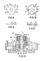
- the second elastically deformable wall portion 18 on the second side 12 of the head-drum system comprises a centring diaphragm of a thin elastic sheet material with a central opening 20, see Figs. 8 and 9.
- the drive spindle 7 is fitted tightly into the central opening 20, which has a shape and dimensions such that, when the head drum system 13 is mounted on the drive spindle 7, portions of the centring diaphragm 18 adjacent the central opening 20 are subjected to an elastic deflection in an axial direction as a result of the forces obtaining between the centring diaphragm and the drive spindle.
- the centring diaphragm 18 is secured with the aid of fixing means which comprises a thrust ring 21 and three bolts 22, which are passed through openings 23 in the centring diaphragm 18 and through openings 24 in the thrust ring 21 and are screwed into the head drum 32.
- the thrust ring 21 is shown in Figs. 10 and 11.
- the thrust ring has a central bore 25, through which the drive spindle 7 passes with clearance.
- the fixing means 21 and 22 cooperate with the centring diaphragm 18 at some distance from its central opening 20, so that the portions of the centring diaphragm situated between the location where the fixing means 21 and 22 cooperate with the centring diaphragm and the central opening 20 are free to a limited extent to be subjected to the elastic deflection.
- the first deformable wall portion 16 comprises an elastically deformable clamping sleeve with a free end 26 and with an outer circumferential surface 27, which is concentric with the drive spindle 7.
- the wall-deforming device 19 comprises a clamping-sleeve deforming device which exerts pressure forces on the outer circumferential surface 27.
- Said clamping sleeve deformation device comprises a clamping ring which is deformable between a released position and a clamping position, which ring has an uninterrupted structure in the circumferentia) direction and through a symmetricl radial deformation exerts a clamping pressure on the clamping sleeve 16, which pressure is substantially uniformly distributed over the circumference.
- the clamping ring has a conical inner wall 28 with a surface which forms part of the generated surface of an imaginary cone, whose axis is constituted by the axis of rotation 6 of the drive spindle 7.
- the apex angle a of the cone is indicated in Fig. 3 between the generatrix 29 of the imaginary cone and an auxiliary line 30 parallel to the axis of rotation 6.
- the angle a is smaller than the friction angle (p of the materials used for the clamping sleeve 16 and the clamping ring 19 so that the frictional forces occurring between the clamping sleeve and the clamping ring will prevent the clamping ring from returning to the released position in an axial direction as a result of the axial components of the clamping force exerted on it in the clamping position.
- the clearance between the drive spindle 7 and the clamping sleeve 16 when the clamping ring is still in its released position does not exceed approximately 15 um and is preferably even smaller.
- a drive spindle diameter of 6 mm it is for example possible to employ a fit which is designated h5/H6 in the I.S.O. system of fits.
- the drive spindle may be undersized to a maximum of 5 pm and the bore in the head drum may be oversized to a maximum of 8 pm.
- the angle a may for example be 1°30'.
- the clamping sleeve 16 is externally provided with a shoulder 31, which is concentric with the axis of rotation 6 of the drive spindle 7, for cooperation with the conical inner wall 28 of the clamping ring 19, so that the clamping sleeve 16 is deformed by the clamping ring 19 at a location which is accurately defined by the shoulder 31.
- FIGs. 5 and 6 show tools for mounting the clamping ring and Fig. 7 the tool for removing it.
- the head drum 32 is provided with a collar 33 which is coaxial with the clamping sleeve 16 for taking up reaction forces exerted on the head-drum system by the auxiliary tools.
- Fig. 5 shows a sleeve 34, on diametrically opposed sides of which two pins 35 are secured and in which a bolt 36 can be tightened or loosened in an axial direction at a central location.
- the sleeve has a flange 37 with a substantially U-shaped recess 38.
- This recess is dimensioned so that the sleeve 34 can be slid around the collar 33 of the head drum, the flange 37 being mounted at the underside of the collar in a circumferential groove 39.
- a thrust member 40 see Fig. 6, is placed on the clamping ring 19.
- the thrust member is provided with three axially extending limbs 41 which bear on the upper surface of the clamping ring 19 around the clamping sleeve 16.
- a conical cavity 43 is formed for receiving a conical end 44 of the thrust bolt 36.
- the clamping ring 19 is urged to its clamping position by tightening the bolt 36, the conical end 44 of the bolt engaging in the conical cavity 43 and the bolt thus pressing on the thrust member 40.
- the two pins 35 on the sleeve 34 may be held manually in order to prevent the sleeve from rotating when the bolt 36 is tightened.
- the axial reaction forces of the auxiliary tool are transmitted to the collar 33 of the head drum 32 by the flange 37.
- the auxiliary tool of Fig. 7 can be used, which tool comprises a bolt 45 with a conical end 46, a ring 47 with a flange 48, three pivotal extraction members 49 and a resilient wire ring 50.
- the extraction members 49 are each provided with an extraction limb 51 with a foot 52.
- the extraction limb 51 is connected to an upper portion 53 having an external surface which substantially forms part of a cylinder and which is formed with a groove 54 for the wire ring 50.
- the upper portion 53 of each extraction member 49 bears on the flange 48 and is resiliently urged against the outside of the ring 47 by the wire ring 50.
- the extraction members 49 are mounted on the ring 47 so as to be slightly movable in a manner such that the extraction limbs 51 can be pivoted slightly outwards, i.e. at least so far that the feet 52 can be fitted over the clamping ring 19.
- the conical end 46 of the threaded bolt 45 is fitted into a conical cavity 55 in the free end 8 of the drive spindle 7.
- the threaded bolt 45 is tightened the feet 52 are moved upwards until they engage with the underside of the clamping ring 19. Further tightening of the threaded bolt results in the clamping ring being released. The axial reaction force of this tool is directly transmitted to the drive spindle 7.
- the centring diaphragm 18 of Figs. 8 and 9 has a thickness of approximately 0.1 mm and is made of a chromium-nickel (18 Cr-8 Ni) spring steel.
- the outer diameter of the centring diaphragm is approximately 20 mm, whilst the three openings 23 for the passage of the bolts 22 are situated on a pitch circle of approximately 16 mm.
- the openings 23 correspond to similar openings 24 in the thrust ring 21.
- the central opening 20 of the centring diaphragm 18 has a diameter of approximately 6 mm, whilst the inner diameter of an annular thrust surface 56 of the thrust ring 21 is approximately 12 mm.
- the distance between the edgeoff the central opening 20 of the centring diaphragm 18 and the thrust surface 56 of the thrust ring 21 is consequently 3 mm.
- the degree of deflection of the portion of the centring diaphragm situated between the centring opening 20 and the thrust surface 56 is shown highly exaggerated in Fig. 3. In reality the axial deflection is not more than approximately 0.2 mm.
- the head-drum system 60 of Fig. 12 is provided with a first clamping device 61 on its first side, which clamping device serves for detachably clamping and thereby also centring the head-drum system 60 on a drive spindle, not shown, which first clamping device thus also functions as the first centring device.
- the first clamping device 61 comprises a first elastically deformable wall portion 62 for cooperation with the drive spindle. On this deformable wall portion pressure forces are exerted by a wall-deforming device to be described in more detail hereinafter, so that the wall portion is elastically deformed and is thus centred and clamped onto the drive spindle.
- a second clamping device 63 has been provided on the other side of the head-drum system 60 and also serves for detachably clamping and thereby centring the head-drum system on the drive spindle, so that the second clamping device also functions as second centring device.
- the second clamping device 63 has a second elastically deformable wall portion 64 and furthermore a wall-deforming device, to be described in more detail hereinafter, which exerts pressure forces on the wall portion 64, which is thereby elastically deformed and thus centres as well as clamps the head-drum system on the drive spindle.
- Three components which cooperate with the wall-deforming device of the second clamping device 63 pass from the first side of the head-drum system through three openings 86 formed in a head drum 65 which forms part of the head-drum system 60. Only one opening is visible in the cross-section of Fig. 12.
- the first and second elastically deformable wall portions 62 and 64 comprise cylindrical clamping sleeves with free ends 66 and 67 which fit concentrically around cylindrical portions of the drive spindle.
- the first and the second wall-deforming devices respectively comprise first and second clamping rings 68 and 69, which fit concentrically around the clamping sleeves 62 and 64 respectively and which are radially deformable between a released position and a clamping position under the influence of axial forces.
- a first pressure bush 70 and a second pressure bush 71 are concentrically arranged around the clamping sleeves 62 and 64 respectively, leaving an annular space for the clamping rings 68 and 69 respectively.
- first and second clamping-ring compressors 72 and 73 which cooperate with the first and second clamping rings 68 and 69 for axially compressing said rings.
- said compressors each comprise an inwardly directed flange on the pressure bush 70 and the pressure bush 71 respectively.
- the head drum 65 is provided with a shoulder 74 at some axial distance from the free end 66 of the first clamping sleeve 62, which shoulder constitutes a stop for the clamping ring 68.
- a stop 75 for the clamping ring 69 On the other side there is provided a stop 75 for the clamping ring 69.
- clamping rings 68 and 69 Cooperating with the clamping ring compressors 72 and 73 are displacement means for moving the clamping-ring compressors in a direction towards the clamping-ring stops 74 and 75 respectively.
- the clamping rings 68 and 69 are moved by axial compression between their released positions and their clamping positions in the annular spaces between the clamping sleeves 62 and 64 respectively and are thus elastically deformed in a radial direction. In this way the clamping sleeves 62 and 64, and thus the head-drum system 60, are clamped and centred on the drive spindle.
- the head drum 65 has three openings 86. These are situated at equal distances from the axis of rotation of the head-drum system 60 and are also spaced at equal angular distances from each other.
- the said displacement means for moving the clamping-ring compressors 72 and 73 towards each other comprise (see Figs. 6 and 7) three extraction members 77 which pass through the openings 86, which members transmit the pulling forces between the two clamping-ring compressors.
- the displacement means comprise screw-thread means for pulling the two clamping-ring compressors 72 and 73 towards each other, inter alia with the aid the extraction members 77 which pass through the openings 86.
- Said screw-threaded means comprise an internally threaded outer bush 78 which is integral with the extraction members, as well as an externally threaded inner bush 79 which cooperates therewith.
- the extraction members 77 are each provided with a threaded bore 80 for a bolt 81 and the threaded inner bush 79 has a number of slots 82 for a tool, not shown.
- the bolts 81 three of which have been provided, extend through openings 83 in an outwardly directed flange 84 which is formed on the pressure bush 71.
- the pressure bush 70 is provided with a smaller flange 85.
- a central bore of the head-drum system 60 has a diameter which is slightly greater than the diameter of the drive spindle on which the head drum system is to be mounted. With respect to the adaption of two diameters to each other, the same rules apply as discussed previously with reference to the embodiment of Fig. 3.
- the threaded inner bush 79 is turned with the aid of a suitable tool, so that at a given instant the bottom of this bush will come into contact with the flange 85 of the pressure bush 70.
- a further rotation of the threaded bush 79 now results in the clamping-ring compressors 72 and 73 being pulled towards each other, so that the clamping rings 68 and 69 are axially compressed in the closed annular spaces in which they are located and thus expand radially and exert pressure on the clamping sleeves 62 and 64, which as a result of this are subjected to a radial deformation which is substantially uniformly distributed over the circumference and thereby centre as well as clamp the head-drum system 60 on the drive spindle on the first side as well as on the second side.
- the threaded bush 79 is loosened, the clamping rings 68 and 69 return from the clamping position to the released position under the influence of their own elasticity.
- the clamping rings as they expand axially meet with a minimal resistance as a result of the friction occurring between their inner walls and the outer walls of the clamping sleeves. It is therefore favourable when the clamping rings are manufactured from a self-lubricating material such as, for example, polytetrafluoroethylene.
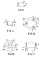
- the head-drum system 90 which is only shown schematically in Fig. 18, comprises a head drum 91 which is mounted on a drive spindle 7 which is rotatable about an axis of rotation 6.
- the head drum On the first side 97 the head drum is formed with a conical cavity 94 at some distance from the central bore 95 of the head drum 91.
- a similar conical cavity 96 is formed on the other side 98 .
- Said conical cavities have inner walls which each form part of a cone whose base faces the first and the second side respectively of the head-drum system. whe first and the second elastically deformable wall portions 99 and 100 are situated between the central bore 95 of the head-drum system and the first and the second conical cavities 94 and 96 respectively.
- a first and a second wall-deforming device comprise a first and a second clamping plug 101 and 102 respectively. They are provided with outer walls which cooperate with the walls of the conical cavities 94 and 96. Furthermore there are provided displacements means which cooperate with the first clamping plug 101 for moving said plug in a direction towards the second side 98 of the head-drum system, and with the second clamping plug 102 for moving said plug in a direction towards the first side 97 of the head-drum system.
- an opening 103 is formed which extends from the first side 97 to the second side 98 of the head drum. This opening accommodates displacement means in the form of a draw-bolt 104.
- the first clamping plug 101 constitutes the head of said draw-bolt 104 and the second clamping plug 102 constitutes a nut fitted on the draw-bolt.
- the clamping plug 101 is formed with a cavity 105 of hexagonal cross-section in which an Allen key can engage for tightening the draw-bolt 104.
- This tightening the clamping plugs 102 and 101 are drawn towards each other, so that pressure forces are exerted on the elastic wall portions 99 and 100, as a result of which said portions are deformed elastically and the head-drum system is centred and at the same time clamped on the drive spindle 7.
- the head-drum system 110 of Fig. 19 closely resembles the head-drum system 13 of Fig. 3, except that now elastically deformable clamping sleeves 114 and 115 have been provided on both the first side 111 and on the second side 112 of the head drum 113. Furthermore there are now provided two clamping rings 116 and 117, which are movable over the conical outer surfaces of the clamping sleeves 114 and 115 between a released position and a clamping position. In order to enable the second clamping ring 117 on the second side 112 of the head drum 113 to be moved from the first side 111, a few, for example, three, openings 118 are formed in the head drum. By means of auxiliary tools, which in principle need not differ much from those shown in Figs. 5 through 7, the clamping ring 116, and via the openings 118 also the clamping ring 117, can be moved between their released positions and their clamping positions and vice versa.
Landscapes
- Adjustment Of The Magnetic Head Position Track Following On Tapes (AREA)
- Tyre Moulding (AREA)
Claims (10)
Applications Claiming Priority (2)
| Application Number | Priority Date | Filing Date | Title |
|---|---|---|---|
| NL7906478A NL7906478A (nl) | 1979-08-29 | 1979-08-29 | Inrichting ten behoeve van het magnetisch inschrijven en uitlezen van signalen van grote bandbreedte. |
| NL7906478 | 1979-08-29 |
Publications (2)
| Publication Number | Publication Date |
|---|---|
| EP0024765A1 EP0024765A1 (fr) | 1981-03-11 |
| EP0024765B1 true EP0024765B1 (fr) | 1985-11-21 |
Family
ID=19833749
Family Applications (1)
| Application Number | Title | Priority Date | Filing Date |
|---|---|---|---|
| EP80200780A Expired EP0024765B1 (fr) | 1979-08-29 | 1980-08-19 | Appareil d'enregistrement ou de reproduction sur bande, à tête magnétique rotative |
Country Status (11)
| Country | Link |
|---|---|
| US (1) | US4395745A (fr) |
| EP (1) | EP0024765B1 (fr) |
| JP (1) | JPS5931125B2 (fr) |
| AT (1) | AT372202B (fr) |
| AU (1) | AU541545B2 (fr) |
| CA (1) | CA1152639A (fr) |
| DD (1) | DD153011A5 (fr) |
| DE (1) | DE3071250D1 (fr) |
| ES (1) | ES8104614A1 (fr) |
| NL (1) | NL7906478A (fr) |
| PL (1) | PL128780B1 (fr) |
Families Citing this family (8)
| Publication number | Priority date | Publication date | Assignee | Title |
|---|---|---|---|---|
| DE3176434D1 (en) * | 1980-02-13 | 1987-10-15 | Philips Nv | Tape recording and/or reproducing apparatus with rotating magnetic head |
| WO1984000438A1 (fr) * | 1982-07-06 | 1984-02-02 | Matsushita Electric Ind Co Ltd | Assemblage de tete rotative |
| AT379909B (de) * | 1984-03-06 | 1986-03-10 | Philips Nv | Aufzeichnungs- und/oder wiedergabegeraet |
| JPS637955Y2 (fr) * | 1984-12-24 | 1988-03-09 | ||
| DE3744203A1 (de) * | 1987-12-24 | 1989-07-06 | Grundig Emv | Einrichtung in einem magnetbandgeraet zur halterung einer kopfradscheibe |
| US5010432A (en) * | 1988-06-28 | 1991-04-23 | Sony Corporation | Rotary head drum apparatus comprising resilient electrical connectors |
| DE4110590C2 (de) * | 1991-04-02 | 1996-01-25 | Broadcast Television Syst | Abtasteinrichtung für ein Magnetbandgerät |
| AT397888B (de) * | 1992-10-14 | 1994-07-25 | Koninkl Philips Electronics Nv | Einrichtung mit einem mit einem elastisch aufweitbaren klemmteil auf einer welle festklemmbaren bauteil, klemmteil für eine solche einrichtung und aufweitvorrichtung zum aufweiten eines solchen klemmteils einer solchen einrichtung |
Family Cites Families (14)
| Publication number | Priority date | Publication date | Assignee | Title |
|---|---|---|---|---|
| US101824A (en) * | 1870-04-12 | Improvement in combined pttlley and clamp | ||
| US2168469A (en) * | 1936-04-29 | 1939-08-08 | Gen Motors Corp | Antifriction bearing |
| US2908541A (en) * | 1955-09-19 | 1959-10-13 | Litton Industries Inc | Magnetic recording apparatus |
| US3021049A (en) * | 1957-01-31 | 1962-02-13 | Gen Electric | Tapered clamping ring for fan and improved hub design |
| US3075049A (en) * | 1958-09-10 | 1963-01-22 | Gordon Sumner | Repetitive scanning of a record track on a fragment of a record |
| DE1227503B (de) * | 1960-01-15 | 1966-10-27 | Siemens Ag | Einstellvorrichtung zum Einstellen der Winkellage von am Umfang einer rotierenden Scheibe angeordneten Magnetkoepfen |
| US3165342A (en) * | 1963-03-29 | 1965-01-12 | Borg Warner | Means for fixing wheels on shafts |
| US3567869A (en) * | 1967-03-07 | 1971-03-02 | Victor Company Of Japan | Magnetic recording and reproducing apparatus with rotating head inclination and height-adjusting means |
| US3548394A (en) * | 1968-02-26 | 1970-12-15 | Scient Data Systems Inc | Rotating magnetic disc storage structure |
| AT339392B (de) * | 1974-06-27 | 1977-10-10 | Grundig Emv | Bandfuhrungsvorrichtung |
| AT371016B (de) * | 1975-03-17 | 1983-05-25 | Adidas Chaussures | Schibindung |
| DE2522581A1 (de) * | 1975-05-22 | 1976-12-09 | Bosch Gmbh Robert | Abtasteinrichtung fuer ein magnetbandgeraet |
| AT345577B (de) * | 1976-07-05 | 1978-09-25 | Philips Nv | Aufzeichnungs- und/oder wiedergabegeraet |
| NL7902292A (nl) * | 1979-03-23 | 1980-09-25 | Philips Nv | Inrichting voor het magnetisch inschrijven en uitlezen van signalen van grote bandbreedte. |
-
1979
- 1979-08-29 NL NL7906478A patent/NL7906478A/nl unknown
-
1980
- 1980-08-19 DE DE8080200780T patent/DE3071250D1/de not_active Expired
- 1980-08-19 EP EP80200780A patent/EP0024765B1/fr not_active Expired
- 1980-08-21 CA CA000358707A patent/CA1152639A/fr not_active Expired
- 1980-08-25 US US06/180,779 patent/US4395745A/en not_active Expired - Lifetime
- 1980-08-26 PL PL1980226419A patent/PL128780B1/pl unknown
- 1980-08-27 ES ES494526A patent/ES8104614A1/es not_active Expired
- 1980-08-27 AU AU61783/80A patent/AU541545B2/en not_active Ceased
- 1980-08-27 DD DD80223550A patent/DD153011A5/de unknown
- 1980-08-28 AT AT0436880A patent/AT372202B/de not_active IP Right Cessation
- 1980-08-29 JP JP55119634A patent/JPS5931125B2/ja not_active Expired
Also Published As
| Publication number | Publication date |
|---|---|
| ATA436880A (de) | 1983-01-15 |
| CA1152639A (fr) | 1983-08-23 |
| AU6178380A (en) | 1981-03-05 |
| AT372202B (de) | 1983-09-12 |
| ES494526A0 (es) | 1981-04-01 |
| DD153011A5 (de) | 1981-12-16 |
| NL7906478A (nl) | 1981-03-03 |
| PL128780B1 (en) | 1984-02-29 |
| EP0024765A1 (fr) | 1981-03-11 |
| JPS5634135A (en) | 1981-04-06 |
| DE3071250D1 (en) | 1986-01-02 |
| JPS5931125B2 (ja) | 1984-07-31 |
| AU541545B2 (en) | 1985-01-10 |
| PL226419A1 (fr) | 1981-07-10 |
| ES8104614A1 (es) | 1981-04-01 |
| US4395745A (en) | 1983-07-26 |
Similar Documents
| Publication | Publication Date | Title |
|---|---|---|
| EP0024765B1 (fr) | Appareil d'enregistrement ou de reproduction sur bande, à tête magnétique rotative | |
| US4541086A (en) | Disc clamping mechanism | |
| US5509752A (en) | Arrangement comprising a shaft, a hub mounted on the shaft by means of an elastically expansible clamping member, and an expansion device for expanding the clamping member | |
| CA1155549A (fr) | Systeme d'ecriture et de lecture de donnees | |
| JPH0346904B2 (fr) | ||
| JPS63142580A (ja) | 情報キャリヤ | |
| US4479157A (en) | Mounting for a head drum of a helical scan recorder | |
| US4321639A (en) | Apparatus for magnetically recording and reading wide-band signals | |
| US5452833A (en) | Magnetic-tape apparatus comprising a pressure-roller device | |
| US3422230A (en) | Mounting structure for rotating magnetic heads | |
| KR840002522Y1 (ko) | 광대역 신호의 자기 기록 및 판독장치 | |
| KR840002521Y1 (ko) | 광대역 신호의 자기 기록 및 판독장치 | |
| US3763327A (en) | Magnetic head wheel rotor and transformer assembly with anti-rotation locking means | |
| KR830000702B1 (ko) | 광대역 신호 자기 기록 및 재생장치 | |
| JPS60234214A (ja) | 記録・再生装置 | |
| JPS6144306Y2 (fr) | ||
| JPS6323787Y2 (fr) | ||
| US5042956A (en) | Recording drum assemblies | |
| JPS6360469B2 (fr) | ||
| JPH0136175B2 (fr) | ||
| JPH10154364A (ja) | ビデオレコーダデッキに対するシンプルなドラム取付け機構 | |
| JPH0722731Y2 (ja) | 回転ヘッド装置 | |
| JPH09180316A (ja) | シリンダ取付装置 | |
| JPH04149855A (ja) | フレキシブル磁気ディスクのクランプ機構 | |
| JPH0736201B2 (ja) | 磁気記録再生装置 |
Legal Events
| Date | Code | Title | Description |
|---|---|---|---|
| PUAI | Public reference made under article 153(3) epc to a published international application that has entered the european phase |
Free format text: ORIGINAL CODE: 0009012 |
|
| AK | Designated contracting states |
Designated state(s): BE CH DE FR GB IT NL SE |
|
| 17P | Request for examination filed |
Effective date: 19810112 |
|
| RAP1 | Party data changed (applicant data changed or rights of an application transferred) |
Owner name: N.V. PHILIPS' GLOEILAMPENFABRIEKEN |
|
| ITF | It: translation for a ep patent filed |
Owner name: ING. C. GREGORJ S.P.A. |
|
| GRAA | (expected) grant |
Free format text: ORIGINAL CODE: 0009210 |
|
| AK | Designated contracting states |
Designated state(s): BE CH DE FR GB IT LI NL SE |
|
| REF | Corresponds to: |
Ref document number: 3071250 Country of ref document: DE Date of ref document: 19860102 |
|
| ET | Fr: translation filed | ||
| PLBE | No opposition filed within time limit |
Free format text: ORIGINAL CODE: 0009261 |
|
| STAA | Information on the status of an ep patent application or granted ep patent |
Free format text: STATUS: NO OPPOSITION FILED WITHIN TIME LIMIT |
|
| 26N | No opposition filed | ||
| PGFP | Annual fee paid to national office [announced via postgrant information from national office to epo] |
Ref country code: NL Payment date: 19870831 Year of fee payment: 8 |
|
| PG25 | Lapsed in a contracting state [announced via postgrant information from national office to epo] |
Ref country code: SE Effective date: 19890820 |
|
| PG25 | Lapsed in a contracting state [announced via postgrant information from national office to epo] |
Ref country code: LI Effective date: 19890831 Ref country code: CH Effective date: 19890831 Ref country code: BE Effective date: 19890831 |
|
| BERE | Be: lapsed |
Owner name: N.V. PHILIPS' GLOEILAMPENFABRIEKEN Effective date: 19890831 |
|
| PG25 | Lapsed in a contracting state [announced via postgrant information from national office to epo] |
Ref country code: NL Effective date: 19900301 |
|
| NLV4 | Nl: lapsed or anulled due to non-payment of the annual fee | ||
| REG | Reference to a national code |
Ref country code: CH Ref legal event code: PL |
|
| PGFP | Annual fee paid to national office [announced via postgrant information from national office to epo] |
Ref country code: GB Payment date: 19900801 Year of fee payment: 11 |
|
| PGFP | Annual fee paid to national office [announced via postgrant information from national office to epo] |
Ref country code: FR Payment date: 19900817 Year of fee payment: 11 |
|
| PGFP | Annual fee paid to national office [announced via postgrant information from national office to epo] |
Ref country code: DE Payment date: 19901025 Year of fee payment: 11 |
|
| PG25 | Lapsed in a contracting state [announced via postgrant information from national office to epo] |
Ref country code: GB Effective date: 19910819 |
|
| GBPC | Gb: european patent ceased through non-payment of renewal fee | ||
| PG25 | Lapsed in a contracting state [announced via postgrant information from national office to epo] |
Ref country code: FR Effective date: 19920430 |
|
| PG25 | Lapsed in a contracting state [announced via postgrant information from national office to epo] |
Ref country code: DE Effective date: 19920501 |
|
| REG | Reference to a national code |
Ref country code: FR Ref legal event code: ST |
|
| EUG | Se: european patent has lapsed |
Ref document number: 80200780.7 Effective date: 19900418 |