EP0024689A1 - Dampferzeuger mit Zwischenwand zwischen zwei Brennkammern - Google Patents
Dampferzeuger mit Zwischenwand zwischen zwei Brennkammern Download PDFInfo
- Publication number
- EP0024689A1 EP0024689A1 EP80104957A EP80104957A EP0024689A1 EP 0024689 A1 EP0024689 A1 EP 0024689A1 EP 80104957 A EP80104957 A EP 80104957A EP 80104957 A EP80104957 A EP 80104957A EP 0024689 A1 EP0024689 A1 EP 0024689A1
- Authority
- EP
- European Patent Office
- Prior art keywords
- steam
- separator
- water
- outlet
- intermediate wall
- Prior art date
- Legal status (The legal status is an assumption and is not a legal conclusion. Google has not performed a legal analysis and makes no representation as to the accuracy of the status listed.)
- Withdrawn
Links
Images

Classifications
-
- F—MECHANICAL ENGINEERING; LIGHTING; HEATING; WEAPONS; BLASTING
- F22—STEAM GENERATION
- F22B—METHODS OF STEAM GENERATION; STEAM BOILERS
- F22B29/00—Steam boilers of forced-flow type
- F22B29/06—Steam boilers of forced-flow type of once-through type, i.e. built-up from tubes receiving water at one end and delivering superheated steam at the other end of the tubes
-
- F—MECHANICAL ENGINEERING; LIGHTING; HEATING; WEAPONS; BLASTING
- F22—STEAM GENERATION
- F22B—METHODS OF STEAM GENERATION; STEAM BOILERS
- F22B35/00—Control systems for steam boilers
- F22B35/06—Control systems for steam boilers for steam boilers of forced-flow type
- F22B35/10—Control systems for steam boilers for steam boilers of forced-flow type of once-through type
- F22B35/101—Control systems for steam boilers for steam boilers of forced-flow type of once-through type operating with superimposed recirculation during starting or low load periods, e.g. composite boilers
-
- F—MECHANICAL ENGINEERING; LIGHTING; HEATING; WEAPONS; BLASTING
- F22—STEAM GENERATION
- F22B—METHODS OF STEAM GENERATION; STEAM BOILERS
- F22B29/00—Steam boilers of forced-flow type
- F22B29/06—Steam boilers of forced-flow type of once-through type, i.e. built-up from tubes receiving water at one end and delivering superheated steam at the other end of the tubes
- F22B29/061—Construction of tube walls
-
- F—MECHANICAL ENGINEERING; LIGHTING; HEATING; WEAPONS; BLASTING
- F22—STEAM GENERATION
- F22B—METHODS OF STEAM GENERATION; STEAM BOILERS
- F22B37/00—Component parts or details of steam boilers
- F22B37/02—Component parts or details of steam boilers applicable to more than one kind or type of steam boiler
- F22B37/40—Arrangements of partition walls in flues of steam boilers, e.g. built-up from baffles
Definitions
- the invention relates to a steam generator according to the preamble of claim 1.
- Such steam generators are known for operation with supercritical pressure. They have proven themselves in operation. However, if such a steam generator is operated to save energy in sliding pressure, difficulties can arise in operating states of subcritical pressure due to the fact that steam formed in the intermediate wall is distributed unevenly over the wall pipes of the surrounding walls.
- Methods are known to improve the uniformity of the distribution of a water-steam mixture on parallel pipes; however, if these pipes are tightly connected to each other by welding to form enclosing walls, particularly high requirements must be placed on the accuracy of the distribution of the steam, because nonuniformity can lead to different mass flows in neighboring pipes and thus to considerable temperature differences. Different temperatures result in thermal stresses that must be avoided. It is an object of the invention to ensure a uniform temperature in the peripheral walls of the combustion chamber. It is obvious to solve this problem by the partition and the surrounding walls are connected in parallel and loaded separately with work equipment.
- Claim 2 shows a circuit that is structurally particularly simple.
- the measure according to claim 3 provides a particularly high level of security with regard to the uniformity of the temperature distribution in the surrounding walls during part-load operation of the steam generator. It also allows the total pressure drop to be reduced at full load, which is reflected in a higher boiler efficiency.
- Claim 5 allows to optimize the pressure drop on the steam generator, which leads to a further improvement in the efficiency of the system.
- the water supplied to the surrounding walls can be subcooled via the bypass line according to claim 6, so that there is no risk that vapor bubbles resulting from the pressure drop in the surrounding walls result in distribution problems.
- Claim 7 finally creates constant hypothermia and thus approximately constant security against distribution difficulties.
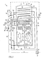
- the steam generator 1 has a lower ring collector 3 and an upper ring collector 4, between which four peripheral walls 5, 6, 7 extend. , fourth
- the surrounding wall is not visible because it lies in front of the cutting plane.
- the surrounding walls consist of inclined parallel wall tubes 10 which are connected to the ring collectors 3 and 4. From a distributor 12, vertical tubes 13, forming a tight partition 14, then extend to a collector 15, as a result of which two combustion chambers 16, 17 are formed within the peripheral walls 5 to 8.
- the combustion chambers are closed off at the bottom by a floor or funnel (not shown).
- the bottom or the funnel walls can form part of the surrounding wall bore.
- Above the ring collector 4, the surrounding walls are continued by an insulated sheet metal box 20 with a rectangular cross section and finally a connection 21 to a chimney 22 is formed.
- a burner 26 and 27 respectively open into the combustion chambers 16 and 17.
- Two bulkhead heating surfaces 28 and 29 are arranged in the upper region of the combustion chambers 16, 17. In the area above the A superheater 30 and then a final superheater 31 and, at the top, an economizer 33 are then provided between the intermediate wall.
- a feed line 34 leads to the economizer 33, and its outlet is connected via a line 35 to the distributor 12 of the intermediate wall 14.
- a connection line 37 leads from the collector 15 to the inlet of a steam separator 40. Its water outlet line 42 is connected via a throttle valve 43 to the lower ring collector 3 of the surrounding walls. This throttle valve 43 is influenced by a level sensor 45 of the steam separator 40 via a controller 46.
- a branch line 48 leads from the feed line 34 via a control valve 49 to a mixing point 50 of the water outlet line 42, which is located upstream of the throttle valve 43.
- the upper ring collector 4 is connected to a water separator 52 via a line 51.
- a water return line 54 with a valve 55 is connected to its water outlet connection and is influenced by a level sensor 56 via a controller 57.
- the water return line 54 is connected to a feed water tank (not shown) via a recuperator 60 arranged in the feed line 34.
- the steam outlet line 62 of the water separator 52 bifurcates at a point 63, from which two line branches 64 and 65 lead to the bulkhead heating surfaces 28 and 29, respectively. The outputs of these bulkhead heating surfaces 28, 29 combine at the input 66 of the superheater 30.
- the output of the superheater 30 is formed by a collector 68, from which a connecting line 69 leads to a collector 70, which at the same time forms the input of the final superheater 31.
- a live steam line 72 leads from the outlet of the final superheater 31 to the consumer, not shown.
- An injection line 74 with an injection valve 75 opens into the connecting line 69, which is connected by a temperature sensor 76 located on the live steam line 72 a controller 77 is influenced.
- feed water flows via the recuperator 60, the economizer 33 and, still subcooled compared to saturated steam temperature, into the distributor 12, from which the water is distributed uniformly into the vertical tubes 13 of the intermediate wall 14.
- a weak quarter of the water flow is evaporated and the mixture thus formed flows into the steam separator 40, in which the steam is separated off and fed to the bulkhead heating surfaces 28, 29 via a line 41 with an adjusting valve 44.
- the saturated water from the separator 40 combines from the line 48, again being slightly subcooled.
- the supercooled water then flows through the throttle valve 43 into the lower ring collector 3, in which it is evenly distributed over the pipes 10, which run to the ring collector 4 in the surrounding walls. In these surrounding walls, for example, 98% of the water is evaporated at 50% load.
- the mixture is then separated in a water separator; the water flows through the line 54 and the recuperator 60, in which it gives off a large part of its sensible heat, to the feed container.
- the steam combines with the steam from the steam separator 40 and flows with it to the bulkhead heating surfaces 28, 29.
- the steam in the superheater 30 is further heated. After re-cooling in the area of the connecting line 69, the final superheating takes place in the final superheater 31. With the final temperature recorded by the injection control 75 to 77, the live steam flows to the consumer.
- the amount of feed water does not fall below a certain limit load during operation, which is preferred between 20 and 40% of the full load is reduced.
- the mass flow ratio of the steam and water leaving the steam separator 40 fluctuates over a very large range: when starting up, no steam is produced at all initially, the ratio of the water to steam mass flow is then infinite, while the load exceeds the limit load mentioned the mass flow ratio is around 3.
- a certain pressure drop must be accumulated at the adjusting valve 44.
- the setting valve 44 is operated for this purpose by hand or automatically according to the load condition.
- a particular advantage of the circuit is that the relatively short tubes 13 of the intermediate wall 14 are always flowed through to their ends by a considerable proportion of water, so that surely no overheating takes place in any of these tubes.
- the pipes of the surrounding walls With the pipes of the surrounding walls, the fact that they run in several walls due to their inclined arrangement ensures that the pipes are evenly heated, so that there is no great difference in the end enthalpies when the distribution is well set. After all, it is conceivable that slight overheating occurs in one or the other of the tubes. This is less dangerous than in the case of the partition wall, because the surrounding walls are largely removed from the gas radiation in their upper area, so that high pipe overtemperature is not to be expected under any circumstances.
- a circulation pump 80 is connected between economizer 33 and intermediate wall 14 and the water separated in separator 52 is returned to circulation pump 80.
- the branch line 48 is on the input side between the circulation pump 80 and Partition 14 connected.
- the control valve 49 is influenced by a controller 85, which receives an actual value from a temperature sensor 86 located in the line 42 and a desired value via a signal line 88 from a second temperature sensor 89 located on the steam separator 40.
- the cooling of the water emerging from the steam separator 40 by the control device 49, 85 to 89 takes place in such a way that the temperature upstream of the throttle valve 43 is lower by a certain amount that can be set on the controller 85 than the temperature on the steam separator 40, which is caused by the temperature sensor 89 is determined.
- the circulation pump 80 is driven, preferably up to approximately 50% load. Above this load, it can run freely or can be switched off in connection with the main flow of the work equipment. Therefore, at a load which is less than 50% of the normal load, a large excess of water is circulated through the intermediate wall 14, the steam separator 40 and the surrounding walls 5 to 8 and the water separator 52.
- the adjustment valve 44 is influenced, for example, by one of the control circuits shown in FIGS. 3a to 3e.
- the level sensor 45 acts on the throttle valve 43 via a controller 90, which may be, for example, PID, in the sense that the throttle valve 43 is opened as the level rises .
- the adjusting valve 44 is adjusted by hand or by a load-dependent control.
- the level sensor 45 influences the adjusting valve 44 via a controller 91, which, in contrast to the controller 90, operates in such a way that the adjusting valve 44 is actuated in the closing direction as the level rises. It may be expedient to use the throttle valve 43 by hand or automatically adjust to the load so that the adjusting valve 44 is always opened as far as possible.
- the throttle valve 43 is influenced by the level sensor 45 and its position is measured by a stroke transmitter 92.
- the signal from the stroke transmitter 92 then goes as an actual value to a controller 93, to which a setpoint for the stroke of the throttle valve 43 is input via a line 94.
- the input of the controller 93 acts on the adjusting valve 44. This cascade connection results in a very low pressure loss.
- the cascade circuit according to FIG. 3d acts analogously to FIG. 3c.
- the level sensor 45 influences the setting valve 44, on which a stroke transmitter 96 is arranged, via a controller 91.
- This circuit also automatically leads to a very small pressure drop.
- the circuit according to FIG. 3e forms a combination of the circuits according to FIG. 3a and 3b.
- the signal from the level sensor 45 is simultaneously fed to the controllers 90 and 91, which adjust the throttle valve 43 and the adjusting valve 44 in different directions of action.
- these circuits can be varied in different ways.
- the two valves can also have a staggered effect instead of simultaneously.
- the circuits shown are also suitable for sliding pressure operation, even if supercritical pressure is reached at high loads. Of course, these conditions require the valves to be actuated accordingly.
- the partition and the surrounding walls are preferably brought into an exclusive series connection.
Landscapes
- Engineering & Computer Science (AREA)
- Physics & Mathematics (AREA)
- Thermal Sciences (AREA)
- Mechanical Engineering (AREA)
- General Engineering & Computer Science (AREA)
- Chemical & Material Sciences (AREA)
- Combustion & Propulsion (AREA)
- Control Of Steam Boilers And Waste-Gas Boilers (AREA)
Applications Claiming Priority (2)
| Application Number | Priority Date | Filing Date | Title |
|---|---|---|---|
| CH764979A CH642155A5 (de) | 1979-08-22 | 1979-08-22 | Dampferzeuger mit zwischenwand zwischen zwei brennkammern. |
| CH7649/79 | 1979-08-22 |
Publications (1)
| Publication Number | Publication Date |
|---|---|
| EP0024689A1 true EP0024689A1 (de) | 1981-03-11 |
Family
ID=4328420
Family Applications (1)
| Application Number | Title | Priority Date | Filing Date |
|---|---|---|---|
| EP80104957A Withdrawn EP0024689A1 (de) | 1979-08-22 | 1980-08-21 | Dampferzeuger mit Zwischenwand zwischen zwei Brennkammern |
Country Status (9)
| Country | Link |
|---|---|
| US (1) | US4325328A (cg-RX-API-DMAC10.html) |
| EP (1) | EP0024689A1 (cg-RX-API-DMAC10.html) |
| JP (1) | JPS5630502A (cg-RX-API-DMAC10.html) |
| KR (1) | KR840000583B1 (cg-RX-API-DMAC10.html) |
| AU (1) | AU535318B2 (cg-RX-API-DMAC10.html) |
| CA (1) | CA1154334A (cg-RX-API-DMAC10.html) |
| CH (1) | CH642155A5 (cg-RX-API-DMAC10.html) |
| IN (1) | IN154507B (cg-RX-API-DMAC10.html) |
| IT (1) | IT1132342B (cg-RX-API-DMAC10.html) |
Cited By (1)
| Publication number | Priority date | Publication date | Assignee | Title |
|---|---|---|---|---|
| EP0197378A1 (de) * | 1985-04-01 | 1986-10-15 | Siemens Aktiengesellschaft | Durchlaufdampferzeuger |
Families Citing this family (7)
| Publication number | Priority date | Publication date | Assignee | Title |
|---|---|---|---|---|
| US4422411A (en) * | 1981-05-29 | 1983-12-27 | International Coal Refining Company | Convective heater |
| US4576121A (en) * | 1984-01-27 | 1986-03-18 | International Coal Refining Company | Convective heater |
| FI117635B (fi) * | 1997-02-25 | 2006-12-29 | Kvaerner Power Oy | Soodakattila |
| CN101666485B (zh) * | 2009-08-25 | 2011-04-13 | 南通万达锅炉股份有限公司 | 双进气双通道模块式余热锅炉 |
| DE102010013098A1 (de) * | 2010-03-29 | 2011-09-29 | Huseyin Atala | Kraftwerk und Verfahren zur Erzeugung von elektrischer Energie mit Dampf |
| ES2611304T3 (es) | 2011-12-21 | 2017-05-08 | Sandvik Intellectual Property Ab | Una caldera de vapor que comprende un elemento de radiación |
| CN106016224A (zh) * | 2016-06-30 | 2016-10-12 | 克雷登热能设备(浙江)有限公司 | 一种水容量不超过30l的蒸汽发生器 |
Citations (7)
| Publication number | Priority date | Publication date | Assignee | Title |
|---|---|---|---|---|
| US3172396A (en) * | 1963-03-25 | 1965-03-09 | Combustion Eng | Wall arrangement for vapor generator |
| US3368534A (en) * | 1964-05-27 | 1968-02-13 | Foster Wheeler Corp | Multiple pass design for once-through steam generators |
| FR2073680A5 (cg-RX-API-DMAC10.html) * | 1969-12-12 | 1971-10-01 | Sulzer Ag | |
| FR2075725A5 (cg-RX-API-DMAC10.html) * | 1970-01-19 | 1971-10-08 | Sulzer Ag | |
| FR2143844A1 (cg-RX-API-DMAC10.html) * | 1971-06-30 | 1973-02-09 | Kraftwerk Union Ag | |
| FR2170583A5 (cg-RX-API-DMAC10.html) * | 1971-12-27 | 1973-09-14 | Foster Wheeler Corp | |
| DE2758278A1 (de) * | 1977-12-27 | 1979-06-28 | Kraftwerk Union Ag | Verfahren zur verbesserung der zulaessigen lastaenderungsgeschwindigkeit eines durchlauf-dampferzeugers |
Family Cites Families (6)
| Publication number | Priority date | Publication date | Assignee | Title |
|---|---|---|---|---|
| US2741228A (en) * | 1951-01-05 | 1956-04-10 | Vorkauf Heinrich | Apparatus and method for the vaporization of liquids in steam-generators comprising more than one vaporization system |
| US2887095A (en) * | 1954-08-20 | 1959-05-19 | Vorkauf Heinrich | Tubular steam boiler |
| US3135244A (en) * | 1961-07-27 | 1964-06-02 | Combustion Eng | Vapor generator |
| DE2101563A1 (de) * | 1971-01-14 | 1972-10-19 | Evt Energie & Verfahrenstech | Verfahren zur Regelung der Heiß dampftemperatur bei Strahlungsdampfer zeuger |
| US3814062A (en) * | 1972-05-27 | 1974-06-04 | Siegener Ag | Waste heat boiler with boiler walls and wall portions of finned pipes |
| CH622332A5 (cg-RX-API-DMAC10.html) * | 1977-09-02 | 1981-03-31 | Sulzer Ag |
-
1979
- 1979-08-22 CH CH764979A patent/CH642155A5/de not_active IP Right Cessation
-
1980
- 1980-07-21 IN IN533/DEL/80A patent/IN154507B/en unknown
- 1980-08-06 US US06/175,881 patent/US4325328A/en not_active Expired - Lifetime
- 1980-08-07 IT IT24042/80A patent/IT1132342B/it active
- 1980-08-19 JP JP11392580A patent/JPS5630502A/ja active Pending
- 1980-08-20 KR KR1019800003286A patent/KR840000583B1/ko not_active Expired
- 1980-08-20 CA CA000358682A patent/CA1154334A/en not_active Expired
- 1980-08-21 EP EP80104957A patent/EP0024689A1/de not_active Withdrawn
- 1980-08-21 AU AU61624/80A patent/AU535318B2/en not_active Ceased
Patent Citations (7)
| Publication number | Priority date | Publication date | Assignee | Title |
|---|---|---|---|---|
| US3172396A (en) * | 1963-03-25 | 1965-03-09 | Combustion Eng | Wall arrangement for vapor generator |
| US3368534A (en) * | 1964-05-27 | 1968-02-13 | Foster Wheeler Corp | Multiple pass design for once-through steam generators |
| FR2073680A5 (cg-RX-API-DMAC10.html) * | 1969-12-12 | 1971-10-01 | Sulzer Ag | |
| FR2075725A5 (cg-RX-API-DMAC10.html) * | 1970-01-19 | 1971-10-08 | Sulzer Ag | |
| FR2143844A1 (cg-RX-API-DMAC10.html) * | 1971-06-30 | 1973-02-09 | Kraftwerk Union Ag | |
| FR2170583A5 (cg-RX-API-DMAC10.html) * | 1971-12-27 | 1973-09-14 | Foster Wheeler Corp | |
| DE2758278A1 (de) * | 1977-12-27 | 1979-06-28 | Kraftwerk Union Ag | Verfahren zur verbesserung der zulaessigen lastaenderungsgeschwindigkeit eines durchlauf-dampferzeugers |
Cited By (1)
| Publication number | Priority date | Publication date | Assignee | Title |
|---|---|---|---|---|
| EP0197378A1 (de) * | 1985-04-01 | 1986-10-15 | Siemens Aktiengesellschaft | Durchlaufdampferzeuger |
Also Published As
| Publication number | Publication date |
|---|---|
| AU6162480A (en) | 1981-04-09 |
| IT8024042A0 (it) | 1980-08-07 |
| AU535318B2 (en) | 1984-03-15 |
| CA1154334A (en) | 1983-09-27 |
| IN154507B (cg-RX-API-DMAC10.html) | 1984-11-03 |
| KR830003686A (ko) | 1983-06-22 |
| US4325328A (en) | 1982-04-20 |
| JPS5630502A (en) | 1981-03-27 |
| KR840000583B1 (ko) | 1984-04-23 |
| IT1132342B (it) | 1986-07-02 |
| CH642155A5 (de) | 1984-03-30 |
Similar Documents
| Publication | Publication Date | Title |
|---|---|---|
| DE2845021C2 (de) | Verfahren zum Anfahren eines Zwanglaufdampferzeugers | |
| DE2747813C3 (de) | Anlage zur Raumheizung und Brauch wasserbereitung | |
| DE102007052234A1 (de) | Verfahren zum Betreiben eines solarthermischen Kraftwerks und solarthermisches Kraftwerk | |
| EP1390606B2 (de) | Vorrichtung zur kühlmittelkühlung einer gasturbine und gas- und dampfturbinenanlage mit einer derartigen vorrichtung | |
| DE19901656A1 (de) | Verfahren und Vorrichtung zur Regelung der Temperatur am Austritt eines Dampfüberhitzers | |
| EP0024689A1 (de) | Dampferzeuger mit Zwischenwand zwischen zwei Brennkammern | |
| DE2544799C3 (de) | Gasbeheizter Dampferzeuger | |
| EP0663561B1 (de) | Dampferzeuger | |
| DE3236979C2 (cg-RX-API-DMAC10.html) | ||
| CH653758A5 (de) | Zwangsdurchlaufkessel. | |
| DE2006409C3 (de) | Im Gleitdruckverfahren betriebener Zwanglaufdampferzeuger | |
| EP2676072B1 (de) | Verfahren zum betreiben eines durchlaufdampferzeugers | |
| DE3004093C2 (de) | Dampferzeuger mit wahlweise zu betreibenden Brennern für zwei Brennstoffe unterschiedlich intensiver Flammenstrahlung | |
| DE1965078B2 (de) | Verfahren zum gleitdruckbetrieb eines zwanglaufdampferzeu gers | |
| DE1961296C3 (de) | Dampferzeuger | |
| EP0549522B1 (de) | Verfahren zum Betrieb eines Zwanglaufdampferzeugers und Zwanglaufdampferzeuger dazu | |
| DE2716292C3 (de) | Verfahren zur Inbetriebnahme von mit Druckfeuerung betriebenen Dampferzeugern | |
| DE671961C (de) | Vorrichtung zum selbsttaetigen Regeln der Speisewasserzufuhr eines mit Zwangdurchlauf betriebenen Einrohrdampferzeugers | |
| DE1965078C (de) | Verfahren zum Gleitdruckbetrieb eines Zwanglauf da mpferzeugers | |
| DE1551269A1 (de) | Verfahren und Vorrichtung zur Verminderung der Beanspruchung eines UEberhitzers in einer Energieerzeugungsanlage | |
| DE4314390C2 (de) | Verfahren zum Betreiben eines hydraulischen Systems | |
| DE1301428B (de) | Zwangdurchlaufdampferzeuger mit Hauptfeuerung und Kleinlastfeuerung | |
| DE1041973B (de) | Dampfkraftanlage | |
| CH640334A5 (en) | Process heat installation | |
| DE1263783B (de) | Verfahren zur Inbetriebnahme von Zwangdurchlaufkesseln |
Legal Events
| Date | Code | Title | Description |
|---|---|---|---|
| PUAI | Public reference made under article 153(3) epc to a published international application that has entered the european phase |
Free format text: ORIGINAL CODE: 0009012 |
|
| 17P | Request for examination filed |
Effective date: 19800821 |
|
| AK | Designated contracting states |
Designated state(s): DE FR |
|
| STAA | Information on the status of an ep patent application or granted ep patent |
Free format text: STATUS: THE APPLICATION IS DEEMED TO BE WITHDRAWN |
|
| 18D | Application deemed to be withdrawn |
Effective date: 19820203 |
|
| RIN1 | Information on inventor provided before grant (corrected) |
Inventor name: MISZAK, PAWEL |