EP0024445B2 - Tunnelvortriebmaschine - Google Patents
Tunnelvortriebmaschine Download PDFInfo
- Publication number
- EP0024445B2 EP0024445B2 EP79103163A EP79103163A EP0024445B2 EP 0024445 B2 EP0024445 B2 EP 0024445B2 EP 79103163 A EP79103163 A EP 79103163A EP 79103163 A EP79103163 A EP 79103163A EP 0024445 B2 EP0024445 B2 EP 0024445B2
- Authority
- EP
- European Patent Office
- Prior art keywords
- boom
- dipper
- mounting ring
- bucket
- excavator
- Prior art date
- Legal status (The legal status is an assumption and is not a legal conclusion. Google has not performed a legal analysis and makes no representation as to the accuracy of the status listed.)
- Expired - Lifetime
Links
- 230000000712 assembly Effects 0.000 claims description 9
- 238000000429 assembly Methods 0.000 claims description 9
- 238000010276 construction Methods 0.000 description 10
- 239000000463 material Substances 0.000 description 5
- 239000004567 concrete Substances 0.000 description 3
- 239000012530 fluid Substances 0.000 description 2
- 125000006850 spacer group Chemical group 0.000 description 2
- 230000003213 activating effect Effects 0.000 description 1
- 238000012423 maintenance Methods 0.000 description 1
- 238000005065 mining Methods 0.000 description 1
- 239000011178 precast concrete Substances 0.000 description 1
- 230000036346 tooth eruption Effects 0.000 description 1
- XLYOFNOQVPJJNP-UHFFFAOYSA-N water Substances O XLYOFNOQVPJJNP-UHFFFAOYSA-N 0.000 description 1
Images


Classifications
-
- E—FIXED CONSTRUCTIONS
- E02—HYDRAULIC ENGINEERING; FOUNDATIONS; SOIL SHIFTING
- E02F—DREDGING; SOIL-SHIFTING
- E02F3/00—Dredgers; Soil-shifting machines
- E02F3/04—Dredgers; Soil-shifting machines mechanically-driven
- E02F3/28—Dredgers; Soil-shifting machines mechanically-driven with digging tools mounted on a dipper- or bucket-arm, i.e. there is either one arm or a pair of arms, e.g. dippers, buckets
- E02F3/30—Dredgers; Soil-shifting machines mechanically-driven with digging tools mounted on a dipper- or bucket-arm, i.e. there is either one arm or a pair of arms, e.g. dippers, buckets with a dipper-arm pivoted on a cantilever beam, i.e. boom
- E02F3/307—Dredgers; Soil-shifting machines mechanically-driven with digging tools mounted on a dipper- or bucket-arm, i.e. there is either one arm or a pair of arms, e.g. dippers, buckets with a dipper-arm pivoted on a cantilever beam, i.e. boom the boom and the dipper-arm being connected so as to permit relative movement in more than one plane
-
- E—FIXED CONSTRUCTIONS
- E21—EARTH OR ROCK DRILLING; MINING
- E21D—SHAFTS; TUNNELS; GALLERIES; LARGE UNDERGROUND CHAMBERS
- E21D9/00—Tunnels or galleries, with or without linings; Methods or apparatus for making thereof; Layout of tunnels or galleries
- E21D9/06—Making by using a driving shield, i.e. advanced by pushing means bearing against the already placed lining
- E21D9/08—Making by using a driving shield, i.e. advanced by pushing means bearing against the already placed lining with additional boring or cutting means other than the conventional cutting edge of the shield
- E21D9/0875—Making by using a driving shield, i.e. advanced by pushing means bearing against the already placed lining with additional boring or cutting means other than the conventional cutting edge of the shield with a movable support arm carrying cutting tools for attacking the front face, e.g. a bucket
Definitions
- the invention relates to a tunnel boring machine comprising:
- This invention is an improvement of the excavator assembly which is the subject matter of co-pending earlier EP-A-14733 (application number 79 103 162.8) and over prior art excavator assemblies mounted on the front of a mounting ring which constitutes the forward portion of the central rotably mounting means.
- Such assemblies may include a large bearing, pinion gears affixed to the outer race of the bearing, driven by motors affixed to a bulkhead in the center of the shield, a generally conical housing extending rearwardly from the bulkhead and which has manifold means at the rear end for rotationally connecting the hydraulic lines from the power source with the hydraulic lines which operate the excavator through the mounting means.
- the invention as claimed is intended to give an improvement over the known excavator and to supply a significantly larger breakout force at the outer periphery of the cutting area of the bucket.
- said boom actuating means is disposed within and extends through that mounting ring with its rearward end being disposed and connected substantially behing said mounting ring to an inner housing member secured to the mouting ring about a pivotal axis transverse to the axis of the mounting ring, wherein actuating means comprise extendible piston-cylinder assemblies.
- bulkhead is in the form of a non-rotatable, substantially cone-shaped housing member, and said inner housing member is cone-shaped and disposed for rotating within said housing member.
- the longitudinal axis of said extendible piston-cylinder assemblies are all disposed in a common plane.
- the rearward pivot point of a boom cylinder is positioned at a rearward point inside the mounting means and behind the forward pivot point of the boom cylinder which is mounted on the upper portion of a preferably "L" shaped boom element.
- the mounting assembly for the excavator is an outer cone shaped housing which is movable longitudinally inside the tunnelling machine on a track or channel which is rigidly mounted within the main shield of the tunnelling machine.
- This outer housing supports, at its rearward end a fixed portion of a rotary manifold through which hydraulic fluids used to move the excavator components are passed.
- the front end of the cone shaped housing is rigidly connected to the inner race of a large bearing which supports a rotatable inner housing on which the excavator is rotably mounted to permit 360 degree movement about the longitudinal axis of the tunnelling machine.
- the inner portion of the excavator is a generally right-angled triangularly shaped boom, pivotably mounted on a mounting ring which comprises the forward portion of the rotatable housing.
- a mounting ring which comprises the forward portion of the rotatable housing.
- This novel mounting structure results in a significantly larger breakout force existing at the outer periphery of the cutting area of the bucket. This improvement is significant if not critical in these types of machines where ground conditions requiring breakout forces of 100 to 300 tons and the rating of the machine is based on the weakest breakout force it can exert, that is, at the periphery of the cutting surface.
- any given ground condition utilizing this invention can utilize smaller cylinders since the differential between the breakout force in the center and periphery is substantially reduced. Under any given available hydraulic pressures and flows, the use of smaller cylinders, which have less hydraulic capacity, results in a more rapid movement of the digging components and faster digging rates.
- the use of the excavator construction of this invention permits the use of single cylinders to perform each movement function, allows economy to be achieved in the original construction and in maintenance. Further, by having single cylinders located in the center of the excavator segments, the supporting pivot points are located on either side thereof giving greater transfer support and providing for a more rigid boom construction when compared with a double piston structure having the support between the two cylinders.
- the excavator structure of this invention permits construction of tunnelling machines of a size hitherto unattainable. Given ground conditions requiring moderate to high breakout forces on the order of 50 to 100 tons, it was not possible to construct tunnelling machines which would deal with these ground conditions on a smaller size of under approximately 15 feet in diameter. In the design of smaller machines, as the diameter was reduced the amount of space was reduced necessitating some scaling down of the size of the components of the excavator. As these sizes were scaled down, the lever arm of the components became smaller necessitating hydraulic cylinders of larger diameter but of a shorter over-all length.
- a tunnel boring machine 10 for tunnelling through material of intermediate hardness.
- the machine 10 includes a hollow cylindrical shield 11 having a front circular cutting edge 12 and a rear edge 13.
- Several jack assemblies (not shown) are positioned between the rear edge of the shield and the front edge of a concrete tunnel line 14 which is formed in increments from quartercylindri- cal precast concrete segments 15.
- the jacks are operated to push the cutting edge 12 against the periphery of the hole being dug to finish the "cut" of the cylindrical hole. Then, after the jacks have been fully extended, they are contracted and then the jack assemblies are retracted so that the concrete segments 15 can be positioned in a ring to form another increment of the tunnel liner 14. Then the jack assemblies are repositioned between the rear edge 13 and the front edge of the tunnel liner 14 for pushing the tunnel boring machine 10 against the material through which the machine is tunnelling.
- a track is laid in the tunnel for carrying flat cars that carry concrete segments 15 to the machine 10 and for carrying gondola cars that are used to haul away material as it is excavated from the front of the tunnel.
- the machine 10 also includes an excavator 16 which is mounted at the front end of the machine 10 and a conveyor 17 for conveying excavated material from the bottom front of the machine. 10 upwardly over the forwardmost gondola car.
- the mounting for the excavator 16 includes a bulkhead 18 which has a rail 19 mounted on each side thereof.
- Each of the rails 19 is received within a channel member 20 fixed within and to the shield 11.
- a piston and cylinder assembly (not shown) is provided for reciprocating the bulkhead 18 along the longitudinal axis of the shield with the rails 19 sliding in the channels 20.
- Mounted to the bulkhead 18 is a fixed housing 22 which extends axially toward the rear of the machine.
- the excavator 16 is rotatably mounted to the fixed bulkhead 18 by means of mounting ring 23 and additional mechanism described below.
- the mounting ring 23 has an ear 24 for pivotally mounting a boom 25 on a boom pivot pin 26.
- a dipper member 27 is pivotally mounted on the boom 25 by means of a dipper pivot pin 28.
- a scoop or bucket 29 having cutting teeth 30 is pivotally mounted on the dipper member 27 by means of a bucket pivot pin 31.
- the boom 25 is pivoted about a pivot axis transverse to the longitudinal axis of the shield 11 on pin 26 by a boom piston and cylinder assembly 32.
- the rearward portion of the piston and cylinder assembly 32 is pivotally mounted in a manner described below, to the rear portion (not shown) of a rotatable housing affixed to mounting ring 23 and its front portion is pivotally mounted to the upper part of the boom 25 through a pin 34 which also mounts the rear portion of a dipper cylinder assembly 35.
- the dipper member 27 is pivoted by the dipper cylinder assembly 35 about a pivot axis transverse to the longitudinal axis of the shield 11 which extends through pin 28.
- the bucket 29 is driven about an axis transverse to the axis of the shield 11 through pin 31 by a bucket cylinder assembly 37.
- a mechanism (not shown in Figure 1 but which may be like that shown in Figure 2) is provided for rotating the mounting ring 23 360 degrees in a plane normal to the central axis of the shield 11.
- the first degree of motion is the reciprocal motion provided by the power mechanism for reciprocating the bulkhead in the channels 20. This movement provides an in and out movement of the excavator 16 along the central axis of the shield 11.
- a second degree of movement is provided by the rotational mounting of the base 23 on the bulkhead 18.
- a third degree of movement is provided by the boom piston and cylinder assembly 32 which provides for movement of the outer end of the boom 25 toward and away from the central axis.
- a fourth degree of movement is provided by the dipper piston and cylinder assembly 35 which provides pivoting movement of the dipper member 27 about the axis of pin 28 on the forward end of the boom 25.
- a fifth degree of movement is provided by the bucket piston and cylinder assembly 37 which provides pivotal movement of the bucket or scoop 29 about the axis of pin 31 on the forward end of the dipper member 27.
- Fig. 2 is a side elevational view of a modified embodiment of the excavator and excavator mounting assembly tunnel boring machine shown in Fig. 1.
- the construction and arrangement of the various parts of the excavator 16 are slightly different from the construction and arrangement of the parts of the excavator 16 shown in Fig. 1.
- the excavator 16 includes a bulkhead 18 having a rail 19 mounted on each side thereof. Each of the rails 19 is received within and slidably moveable within one of the two channel members (not shown) positioned on either side of the shield. It differs from the structure of Fig. 1 in that the rear of dipper piston and cylinder assembly 35 is mounted on a separate pivot pin 39 at the rearward portion of boom 25 rather than at the boom piston and cylinder assembly driving pin 34, an option which can be useful where lower hydraulic pressures are used.
- a motor 44 drives a pinion gear 46 which drives a ring gear 48 rigidly attached to or forward an integral part of the mounting ring 23.
- Ring gear 48 is on the outside of and affixed to an outer race 47 of a bearing 42.
- An inner race 49 of bearing 42 is affixed to the bulkhead 18.
- a rear housing assembly 51 includes a cone-shaped housing 52 which supports the inner bearing race 49 at its forward end and which surrounds an inner housing member 53 which is secured to and rotates with the mounting ring 23.
- Hydraulic fluid is supplied to the various cylinders through a rotary manifold including outer stationary part 54 and an inner rotatable part 55 affixed to and rotates with the inner housing member 53.
- Mounting ear 40 is affixed to the back wall of rotatable housing 53.
- Boom cylinder and piston assembly 32 is pivotably mounted on ear 40 by pivot pin 33.
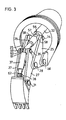
- FIG. 3 shows boom piston and cylinder assembly 32 with a clevis 56 pivotally connected to pin 34.
- the rear end of dipper piston and cylinder assembly 35 has a clevis 57 also mounted on pin 34.
- Spacers 58 hold clevises 56 and 57 centered between boom segments.
- dipper piston and cylinder assembly 35 has a clevis 59 and with clevis 60 on the rearward end of bucket piston and cylinder assembly 37 are pivotally mounted on pin 36.
- Spacers 61 center clevises 59 and 60 between the two segments of dipper 27.
- bucket piston and cylinder assembly 37 has a clevis 62 mounted on pin 38 to drive the bucket around the axis of pin 31.
- extension of dipper piston and cylinder assembly 35 drives the dipper and bucket about the axis of pin 28 and extension of boom piston and cylinder assembly 32 drives the bucket, dipper and boom assembly about the axis of pin 26.
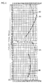
- Figure 4 shows that breakout force at the cutting edge of bucket scoop 29 is even more uniform about the total circular area of movement of the bucket scoop 29 from the central axis of the shield 11, radially outward to a point near the circumference of the shield 11.
- Figure 4 shows the breakout force for a boom bucket combination which is approximately 16 feet from the central axis.
- Line 63 shows the breakout force for the rear end of the boom bucket dipper excavator shown in co-pending earlier EP-A-14733 which has the boom piston and cylinder assembly mounted on an ear projecting from a mounting ring.
- Line 64 depicts the breakout force of a modified form of excavator having the boom and dipper elements locked with respect to each other or replaced by a longer boom element having the same length as those two elements.
- Line 65 depicts the breakout force of the excavator described above in applicant's preferred embodiment.
- Line 66 shows the breakout force of a modified form of the excavator assembly described in this application which has a longer boom of the same length as the boom and dipper or if the boom and dipper were immovable with respect to each other.
Landscapes
- Engineering & Computer Science (AREA)
- Mining & Mineral Resources (AREA)
- Geology (AREA)
- Life Sciences & Earth Sciences (AREA)
- General Life Sciences & Earth Sciences (AREA)
- Geochemistry & Mineralogy (AREA)
- Environmental & Geological Engineering (AREA)
- Mechanical Engineering (AREA)
- Civil Engineering (AREA)
- General Engineering & Computer Science (AREA)
- Structural Engineering (AREA)
- Excavating Of Shafts Or Tunnels (AREA)
- Earth Drilling (AREA)
Claims (3)
Priority Applications (1)
| Application Number | Priority Date | Filing Date | Title |
|---|---|---|---|
| AT79103163T ATE4339T1 (de) | 1979-08-10 | 1979-08-27 | Tunnelbohrmaschine. |
Applications Claiming Priority (2)
| Application Number | Priority Date | Filing Date | Title |
|---|---|---|---|
| US64162 | 1979-08-10 | ||
| US06/064,162 US4349230A (en) | 1979-08-10 | 1979-08-10 | Tunnel boring machine |
Publications (3)
| Publication Number | Publication Date |
|---|---|
| EP0024445A1 EP0024445A1 (de) | 1981-03-11 |
| EP0024445B1 EP0024445B1 (de) | 1983-07-27 |
| EP0024445B2 true EP0024445B2 (de) | 1992-03-04 |
Family
ID=22053985
Family Applications (1)
| Application Number | Title | Priority Date | Filing Date |
|---|---|---|---|
| EP79103163A Expired - Lifetime EP0024445B2 (de) | 1979-08-10 | 1979-08-27 | Tunnelvortriebmaschine |
Country Status (6)
| Country | Link |
|---|---|
| US (1) | US4349230A (de) |
| EP (1) | EP0024445B2 (de) |
| AT (1) | ATE4339T1 (de) |
| BR (1) | BR8002153A (de) |
| CA (1) | CA1142188A (de) |
| DE (1) | DE2965993D1 (de) |
Families Citing this family (10)
| Publication number | Priority date | Publication date | Assignee | Title |
|---|---|---|---|---|
| US4387928A (en) * | 1981-03-27 | 1983-06-14 | Milwaukee Boiler Manufacturing Co. | Tunnel excavator |
| AT380729B (de) * | 1984-09-20 | 1986-06-25 | Voest Alpine Ag | Schraemmaschine |
| AT400878B (de) * | 1990-12-18 | 1996-04-25 | Voest Alpine Bergtechnik | Tunnelvortriebsverfahren sowie schildvortriebsmaschine zur durchführung dieses verfahrens |
| DE4335753C2 (de) * | 1993-10-20 | 1998-07-09 | Schaeff Karl Gmbh & Co | Hydraulisch angetriebener Abbaubagger für eine Vortriebseinrichtung zum unterirdischen Vortrieb |
| US8631595B2 (en) * | 2011-06-22 | 2014-01-21 | Jason Wayne McDonald | Excavating apparatus with swivel mount employing swivel adapter with gear bearings having gears with divergent thickness |
| US8621770B1 (en) * | 2012-06-22 | 2014-01-07 | Jason Wayne McDonald | Excavating apparatus employing swivel adapter with gear bearings having gears with divergent thickness |
| CN105863664B (zh) * | 2016-06-13 | 2018-02-27 | 韶关市铁友建设机械有限公司 | 一种挖掘顶管机 |
| CN105909266A (zh) * | 2016-06-22 | 2016-08-31 | 济南轨道交通集团有限公司 | 一种适用于地下工程暗挖施工的专用掘进设备 |
| CN109184682B (zh) * | 2018-09-26 | 2020-06-12 | 中国神华能源股份有限公司 | 一种铲斗 |
| CN110056363B (zh) * | 2019-04-19 | 2020-06-02 | 中国矿业大学 | 一种滚刀主动旋转的坚硬岩石巷隧道掘进机 |
Family Cites Families (14)
| Publication number | Priority date | Publication date | Assignee | Title |
|---|---|---|---|---|
| US3404920A (en) * | 1966-07-13 | 1968-10-08 | John R. Tabor | Tunneling machine with shield supported traveling excavator |
| CH471944A (de) * | 1968-07-09 | 1969-04-30 | Hydrel Ag Maschf | Vorrichtung für den Abbau und das Abräumen von Erdreich, insbesondere für den Rohrvortrieb und Stollenbau |
| US3556599A (en) * | 1968-12-10 | 1971-01-19 | Tyman H Fikse | Method of tunneling and tunneling shield with a drag loader |
| DE1913581A1 (de) * | 1969-03-18 | 1970-10-01 | Krupp Gmbh | Maschine fuer Untertagearbeiten |
| DD103296A1 (de) * | 1973-04-11 | 1974-01-12 | ||
| CA1002752A (en) * | 1973-08-23 | 1977-01-04 | Caterpillar Tractor Co. | Impact material fracturing device for excavators and the like |
| DE2423171A1 (de) * | 1974-05-13 | 1975-11-20 | Linden Alimak Ab | Schachtraeumgeraet |
| GB1476771A (en) * | 1974-05-29 | 1977-06-16 | Komatsu Mfg Co Ltd | Excavator |
| DE2437669C3 (de) * | 1974-08-05 | 1978-04-27 | Gewerkschaft Eisenhuette Westfalia, 4670 Luenen | Vortriebsvorrichtung für das Auffahren von Tunneln, Stollen und Strecken |
| US3999805A (en) * | 1974-11-26 | 1976-12-28 | Lockwood Bennett Ltd. | Articulated support |
| GB1565803A (en) * | 1975-10-15 | 1980-04-23 | Dobson Park Ind | Mining and like machinery |
| DE2621674C3 (de) * | 1976-05-15 | 1978-11-09 | Bochumer Eisenhuette Heintzmann Gmbh & Co, 4630 Bochum | Verfahren und Vorrichtung zum Vortrieb und Ausbau einer untertägigen Strecke sowie Streckenausbau zur Ausübung des Verfahrens |
| DE2741637A1 (de) * | 1977-09-15 | 1979-03-22 | Goeppner Kaiserslautern Eisen | Vorrichtung zum vortrieb von tunnel- und stollenroehren |
| FR2406702A1 (fr) * | 1977-10-24 | 1979-05-18 | Chantiers Modernes Sa | Fleche support de brise-roche hydraulique |
-
1979
- 1979-08-10 US US06/064,162 patent/US4349230A/en not_active Expired - Lifetime
- 1979-08-27 AT AT79103163T patent/ATE4339T1/de not_active IP Right Cessation
- 1979-08-27 DE DE7979103163T patent/DE2965993D1/de not_active Expired
- 1979-08-27 EP EP79103163A patent/EP0024445B2/de not_active Expired - Lifetime
-
1980
- 1980-02-19 CA CA000345923A patent/CA1142188A/en not_active Expired
- 1980-04-08 BR BR8002153A patent/BR8002153A/pt unknown
Also Published As
| Publication number | Publication date |
|---|---|
| EP0024445A1 (de) | 1981-03-11 |
| US4349230A (en) | 1982-09-14 |
| EP0024445B1 (de) | 1983-07-27 |
| ATE4339T1 (de) | 1983-08-15 |
| CA1142188A (en) | 1983-03-01 |
| BR8002153A (pt) | 1981-03-31 |
| DE2965993D1 (en) | 1983-09-01 |
Similar Documents
| Publication | Publication Date | Title |
|---|---|---|
| US4630869A (en) | Shield tunneling machine | |
| EP0024445B2 (de) | Tunnelvortriebmaschine | |
| CA1139324A (en) | Articulated boom-dipper-bucket assembly for a tunnel boring machine | |
| US3598445A (en) | Tunnel-boring machine | |
| JPS61172993A (ja) | シ−ルドトンネル掘進装置 | |
| US3963080A (en) | Tunneling machine for boring a side drift | |
| CN109386290B (zh) | 一种可伸缩式分体刀盘 | |
| CN114233318A (zh) | 一种截割部整体伸缩的多功能掘进机 | |
| GB2186611A (en) | Pipe-driving apparatus | |
| US3966256A (en) | Tunneling equipment | |
| JP2611896B2 (ja) | トンネル掘削機 | |
| US5915790A (en) | Tunnel boring machine | |
| US4190294A (en) | Excavator for use in a tunneling shield | |
| CN216406826U (zh) | 地下回廊施工掘进装置 | |
| CN113898359B (zh) | 隧道掘进机及掘进机用辅助开挖装置 | |
| JP3136456B2 (ja) | トンネル掘削機の方向制御装置 | |
| JP3653684B2 (ja) | 掘削機 | |
| CN223689709U (zh) | 一种掘进机 | |
| CN119878192B (zh) | 一种隧道掘进机主机及隧道掘进机 | |
| JP4179434B2 (ja) | トンネル掘削機 | |
| JPS6146640B2 (de) | ||
| JPH1018781A (ja) | トンネル掘削機及び掘削方法 | |
| JP3696303B2 (ja) | 拡大シールド掘削装置 | |
| JP3576426B2 (ja) | トンネル掘削機 | |
| CN121738622A (zh) | 一种双模式tbm掘进机及其模式转换方法 |
Legal Events
| Date | Code | Title | Description |
|---|---|---|---|
| PUAI | Public reference made under article 153(3) epc to a published international application that has entered the european phase |
Free format text: ORIGINAL CODE: 0009012 |
|
| AK | Designated contracting states |
Designated state(s): AT BE CH DE FR GB IT LU NL SE |
|
| 17P | Request for examination filed |
Effective date: 19810407 |
|
| ITF | It: translation for a ep patent filed | ||
| GRAA | (expected) grant |
Free format text: ORIGINAL CODE: 0009210 |
|
| AK | Designated contracting states |
Designated state(s): AT BE CH DE FR GB IT LU NL SE |
|
| PG25 | Lapsed in a contracting state [announced via postgrant information from national office to epo] |
Ref country code: NL Effective date: 19830727 Ref country code: CH Effective date: 19830727 |
|
| REF | Corresponds to: |
Ref document number: 4339 Country of ref document: AT Date of ref document: 19830815 Kind code of ref document: T |
|
| PG25 | Lapsed in a contracting state [announced via postgrant information from national office to epo] |
Ref country code: LU Free format text: LAPSE BECAUSE OF NON-PAYMENT OF DUE FEES Effective date: 19830831 |
|
| PGFP | Annual fee paid to national office [announced via postgrant information from national office to epo] |
Ref country code: SE Payment date: 19830831 Year of fee payment: 5 |
|
| REF | Corresponds to: |
Ref document number: 2965993 Country of ref document: DE Date of ref document: 19830901 |
|
| ET | Fr: translation filed | ||
| ET1 | Fr: translation filed ** revision of the translation of the patent or the claims | ||
| NLV1 | Nl: lapsed or annulled due to failure to fulfill the requirements of art. 29p and 29m of the patents act | ||
| PLBI | Opposition filed |
Free format text: ORIGINAL CODE: 0009260 |
|
| 26 | Opposition filed |
Opponent name: GEWERKSCHAFT EISENHUETTE WESTFALIA Effective date: 19840410 |
|
| RTI2 | Title (correction) |
Free format text: TUNNEL DRIVING MACHINE. |
|
| PLAB | Opposition data, opponent's data or that of the opponent's representative modified |
Free format text: ORIGINAL CODE: 0009299OPPO |
|
| R26 | Opposition filed (corrected) |
Opponent name: GEWERKSCHAFT EISENHUETTE WESTFALIAGMBH Effective date: 19840410 |
|
| PG25 | Lapsed in a contracting state [announced via postgrant information from national office to epo] |
Ref country code: SE Effective date: 19860828 |
|
| REG | Reference to a national code |
Ref country code: FR Ref legal event code: TP |
|
| REG | Reference to a national code |
Ref country code: GB Ref legal event code: 732 |
|
| PLAB | Opposition data, opponent's data or that of the opponent's representative modified |
Free format text: ORIGINAL CODE: 0009299OPPO |
|
| R26 | Opposition filed (corrected) |
Opponent name: GEWERKSCHAFT EISENHUETTE WESTFALIA GMBH Effective date: 19840410 |
|
| RAP2 | Party data changed (patent owner data changed or rights of a patent transferred) |
Owner name: VOEST-ALPINE AKTIENGESELLSCHAFT |
|
| PGFP | Annual fee paid to national office [announced via postgrant information from national office to epo] |
Ref country code: CH Payment date: 19910715 Year of fee payment: 13 |
|
| PGFP | Annual fee paid to national office [announced via postgrant information from national office to epo] |
Ref country code: AT Payment date: 19910722 Year of fee payment: 13 |
|
| REG | Reference to a national code |
Ref country code: FR Ref legal event code: TP |
|
| REG | Reference to a national code |
Ref country code: GB Ref legal event code: 732 |
|
| PUAH | Patent maintained in amended form |
Free format text: ORIGINAL CODE: 0009272 |
|
| STAA | Information on the status of an ep patent application or granted ep patent |
Free format text: STATUS: PATENT MAINTAINED AS AMENDED |
|
| 27A | Patent maintained in amended form |
Effective date: 19920304 |
|
| AK | Designated contracting states |
Kind code of ref document: B2 Designated state(s): AT BE CH DE FR GB IT LU NL SE |
|
| REG | Reference to a national code |
Ref country code: CH Ref legal event code: AEN |
|
| PG25 | Lapsed in a contracting state [announced via postgrant information from national office to epo] |
Ref country code: AT Effective date: 19920604 |
|
| REG | Reference to a national code |
Ref country code: CH Ref legal event code: PL |
|
| ET3 | Fr: translation filed ** decision concerning opposition | ||
| PGFP | Annual fee paid to national office [announced via postgrant information from national office to epo] |
Ref country code: BE Payment date: 19920717 Year of fee payment: 14 |
|
| ITTA | It: last paid annual fee | ||
| PG25 | Lapsed in a contracting state [announced via postgrant information from national office to epo] |
Ref country code: BE Effective date: 19930831 |
|
| BERE | Be: lapsed |
Owner name: VOEST-ALPINE A.G. Effective date: 19930831 |
|
| PGFP | Annual fee paid to national office [announced via postgrant information from national office to epo] |
Ref country code: FR Payment date: 19940719 Year of fee payment: 16 |
|
| EUG | Se: european patent has lapsed |
Ref document number: 79103163.6 Effective date: 19870812 |
|
| PG25 | Lapsed in a contracting state [announced via postgrant information from national office to epo] |
Ref country code: FR Effective date: 19960430 |
|
| REG | Reference to a national code |
Ref country code: FR Ref legal event code: ST |
|
| PGFP | Annual fee paid to national office [announced via postgrant information from national office to epo] |
Ref country code: GB Payment date: 19970716 Year of fee payment: 19 |
|
| PGFP | Annual fee paid to national office [announced via postgrant information from national office to epo] |
Ref country code: DE Payment date: 19970804 Year of fee payment: 19 |
|
| PG25 | Lapsed in a contracting state [announced via postgrant information from national office to epo] |
Ref country code: GB Free format text: LAPSE BECAUSE OF NON-PAYMENT OF DUE FEES Effective date: 19980827 |
|
| GBPC | Gb: european patent ceased through non-payment of renewal fee |
Effective date: 19980827 |
|
| PG25 | Lapsed in a contracting state [announced via postgrant information from national office to epo] |
Ref country code: DE Free format text: LAPSE BECAUSE OF NON-PAYMENT OF DUE FEES Effective date: 19990601 |
|
| APAH | Appeal reference modified |
Free format text: ORIGINAL CODE: EPIDOSCREFNO |