EP0021876B1 - Stoppage device for immobilizing doors and gates - Google Patents
Stoppage device for immobilizing doors and gates Download PDFInfo
- Publication number
- EP0021876B1 EP0021876B1 EP19800400714 EP80400714A EP0021876B1 EP 0021876 B1 EP0021876 B1 EP 0021876B1 EP 19800400714 EP19800400714 EP 19800400714 EP 80400714 A EP80400714 A EP 80400714A EP 0021876 B1 EP0021876 B1 EP 0021876B1
- Authority
- EP
- European Patent Office
- Prior art keywords
- door
- ground
- stop element
- projection
- stop
- Prior art date
- Legal status (The legal status is an assumption and is not a legal conclusion. Google has not performed a legal analysis and makes no representation as to the accuracy of the status listed.)
- Expired
Links
Images
Classifications
-
- E—FIXED CONSTRUCTIONS
- E05—LOCKS; KEYS; WINDOW OR DOOR FITTINGS; SAFES
- E05B—LOCKS; ACCESSORIES THEREFOR; HANDCUFFS
- E05B15/00—Other details of locks; Parts for engagement by bolts of fastening devices
- E05B15/02—Striking-plates; Keepers; Bolt staples; Escutcheons
- E05B15/0205—Striking-plates, keepers, staples
-
- Y—GENERAL TAGGING OF NEW TECHNOLOGICAL DEVELOPMENTS; GENERAL TAGGING OF CROSS-SECTIONAL TECHNOLOGIES SPANNING OVER SEVERAL SECTIONS OF THE IPC; TECHNICAL SUBJECTS COVERED BY FORMER USPC CROSS-REFERENCE ART COLLECTIONS [XRACs] AND DIGESTS
- Y10—TECHNICAL SUBJECTS COVERED BY FORMER USPC
- Y10T—TECHNICAL SUBJECTS COVERED BY FORMER US CLASSIFICATION
- Y10T292/00—Closure fasteners
- Y10T292/68—Keepers
Definitions
- the present invention relates to a stop device intended to immobilize a door in cooperation with a floor latch, in particular when the door is in its normal closed position, of the type comprising a stop element intended to be fixed to the floor comprising a front part provided with a protrusion constituting a stop for the door and a rear part located substantially at ground level, in which a hole is made for receiving the free end of the floor latch when the door is immobilized against protuberance.
- US-A-1 488 611 describes a stop device of this type, the bore for which receives the free end of the ground bolt risks at all times being obstructed by earth or by any other entrained material for example by passers-by or by the door when it is folded down.
- the lock quickly ends up being unable to penetrate the bore, which prevents it from exercising its function.
- FR-A-832 297 describes another stop device of this type, the bore for which receives the free end of the ground lock is closed by a shutter finger urged upwards by a spring.
- This finger which is intended to prevent foreign materials from entering the hole, however, complicates the structure of the stop device and also risks seizing up under the effect of bad weather.
- the present invention proposes to remedy the drawbacks exposed above and to do this, it relates to a stop device of the aforementioned type, which is characterized in that it further comprises a recess located in the ground and comprising an inlet closed in part by the stop element and in part by at least one removable cover situated substantially in the same plane as the stop element, the bore being located above the entrance to the recess .
- the recess is constituted by a housing sealed in the ground and open on its upper face.
- the installation of the stop device can be carried out quickly since the housing can for example be prefabricated.
- the bottom of the housing is pierced with a hole, which allows the evacuation of rainwater which would enter the housing.
- the underside of the cover is provided with a slot cooperating with the underside of the cover.
- the walls of the housing are provided at their upper end with a rebate cooperating with the underside of the cover.
- the cover can be easily and quickly centered on the housing, while being immobilized laterally.
- the hole intended to receive the free end of the floor latch is located opposite the protuberance.
- This embodiment is essentially used to immobilize gates with one or two doors with manual locking, in which the floor lock is carried by the door which abuts against the protuberance.
- the bore intended to receive the ground ferrour is offset laterally with respect to the protuberance.
- This embodiment is essentially used to immobilize electrically locked gates comprising two doors, the first of which is stopped by the protuberance and the second, which carries an electrically operated lock, is immobilized against a rebate of the first, or part of protuberance.
- the protuberance is hollow and has on its abutment face a notch communicating with the recess and intended to receive a lug protruding from the door, when the latter is in abutment against the protuberance.
- the stop element is an attached part, the front and rear parts of which are provided with flanks running along the external faces of two opposite walls of the housing and ending in divergent sealing lugs.
- the stop element is an integral part of the housing.
- the stop device according to the invention provides many. advantages, in particular, that of preventing the obturation of the hole intended to receive the ground lock. For full effectiveness of the stop device according to the invention, it must of course be taken care of periodically emptying the recess which can be accessed through the cover.
- the stop device according to the invention provides another advantage residing in the vertical immobilization of closed doors or gates, which prohibits their opening by break-in while allowing to depend quickly without unbolting or unbuttoning the gate for maintenance when is placed in the open position.
- the stop devices according to the invention can be of any size and find their application in the immobilization of gates and doors of all sizes, with manual or electric locking.
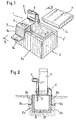
- Figures 1 and 2 show a first embodiment of the invention which comprises a stop element 1 disposed on a housing 2 serving as a recess.
- the stop element 1 comprises a front part 3 provided with a protuberance 4 constituting a stop stop for a door P and a rear part 5 in which a hole 6 is made which is intended to receive the free end of a floor lock V provided on the door P.
- the housing 2 is open on its upper face by an inlet 2 'which is closed in part by the stop element 1 and in part by a removable cover 7 located substantially in the same plane that the stop element 1 when it is positioned on the housing 2.
- the stop element 1 thus communicates with the interior of the housing by the hole 6.
- the housing 2 appears in FIG. 1 in the form of a parallelepiped. But it is obvious that it could be of any other shape, provided that its dimensions are adapted to the size of the stop element 1. It can be made of any building material and preferably prefabricated.
- the housing 2 is constituted by vertical or oblique walls and by a bottom 9 pierced with a hole 10 intended for the evacuation of rain water or runoff which could accumulate during interior.
- the cover 7 has on its underside a rebate 7a which cooperates with the inner faces of the walls of the housing 2 when it is closed to allow rapid centering and lateral immobilization of the cover 7.
- the walls of the housing 2 could be provided at their upper end with a rebate cooperating with the underside of the cover 7. This would thus obtain the same result as above.
- the stop element 1 is constituted by an insert, provided laterally with two sides 8a and 8b along the outer faces 2a and 2b of two opposite walls of the housing 2.
- This insert has the shape of an inverted U so as to be able to adapt to the parallelepipedic housing 2. But it goes without saying that it could be of a different shape, corresponding to the outside shape of the particular case 2 used.
- the stop element 1 has sealing tabs 9a and 9b which extend towards the outside of the housing 2, from the free end of each of the sides 8a and 8b, these tabs ensuring the sealing in the ground of the stop element 1 positioned on the housing 2.
- the stop member 1 could be an integral part of the housing, being molded with the housing 2, either by being secured by any means to it.
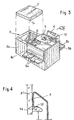
- Figures 3 and 4 show another embodiment of the invention in which the stop member carries a lateral extension 11 and is provided with sides 8a and 8b, themselves provided with sealing lugs 9a and 9b.
- the bore 6, intended to receive the free end of the floor latch is produced in the lateral extension 11.
- This arrangement by which the bore 6 is offset laterally with respect to the protrusion 4 can be envisaged when the floor latch is carried by that of the two doors which does not come into contact with the protuberance 4, for example when it is electrically controlled.
- An attached plate can advantageously be fixed to the periphery of the bore 6 so as to cooperate with the electric lock when the latter is not long enough.
- the protuberance 4 is hollow and has on the abutment face a notch 12 communicating with the recess by an opening 13.
- the notch 12 is intended to receive a lug 14 projecting from the door P 'when the latter is in abutment against the protuberance 4. In this way it is impossible to lift the door and open it fraudulently.
- the opening 13 it allows the materials entrained by the door against the protrusion 4 to fall into the recess.
- the protuberance 4 of the device shown in FIG. 1 could be produced in a similar manner.
- the housing 2 of the stop device according to the invention is generally made of a material based on cement or other binder. But it can possibly be made of metal, cast iron, plastic, or other material. As for the stop element, it is generally made of steel or cast iron.
- the inventive stop device can be used to immobilize doors or gates of very different types, both in their closed position and in their open position. To do this, it will be sealed in the ground so that the housing cover comes substantially to the ground level and so that only the protrusion protrudes from the ground. It will be placed in a place such that it can cooperate with the floor lock, in the desired position of immobilization of the door or of the corresponding portal. For example, for the immobilization in the closed position of a gate with two doors, it will be placed at the level of the line of intersection of the two doors.
Abstract
Description
La présente invention concerne un dispositif d'arrêt destiné à immobiliser une porte en coopération avec un verrou de sol, notamment lorsque la porte est dans sa position normale de fermeture, du type comprenant un élément d'arrêt destiné à etre fixé au sol comportant un partie antérieure pourvue d'une protubérance constituant une butée d'arrêt pour la porte et une partie postérieure située sensiblement au niveau du sol, dans laquelle est réalisé un perçage destiné à recevoir l'extrémité libre du verrou de sol lorsque la porte est immobilisée contre la protubérance.The present invention relates to a stop device intended to immobilize a door in cooperation with a floor latch, in particular when the door is in its normal closed position, of the type comprising a stop element intended to be fixed to the floor comprising a front part provided with a protrusion constituting a stop for the door and a rear part located substantially at ground level, in which a hole is made for receiving the free end of the floor latch when the door is immobilized against protuberance.
US-A-1 488 611 décrit un dispositif d'arrêt de ce type dont le perçage destiné à recevoir l'extrémité libre du verrou de sol risque à tout moment d'être obstrué par de la terre ou par toutes autres matières entraînées par exemple par des passants ou par la porte lors de son rabattement. Ainsi, le verrou finit rapidement par ne plus pouvoir pénétrer dans le perçage, ce que l'empêche d'exercer sa fonction.US-A-1 488 611 describes a stop device of this type, the bore for which receives the free end of the ground bolt risks at all times being obstructed by earth or by any other entrained material for example by passers-by or by the door when it is folded down. Thus, the lock quickly ends up being unable to penetrate the bore, which prevents it from exercising its function.
FR-A-832 297 décrit un autre dispositif d'arrêt de ce type dont le perçage destiné à recevoir l'extrémité libre du verrou de sol est fermé par un doigt obturateur sollicité vers le haut par un ressort. Ce doigt, qui est destiné à interdire aux matières étrangères de pénétrer- dans le perçage complique toutefois la structure du lispositif d'arrêt et risque en outre de se gripper sous l'effet des intempéries.FR-A-832 297 describes another stop device of this type, the bore for which receives the free end of the ground lock is closed by a shutter finger urged upwards by a spring. This finger, which is intended to prevent foreign materials from entering the hole, however, complicates the structure of the stop device and also risks seizing up under the effect of bad weather.
La présente invention se propose de remédier aux inconvénients exposés ci-dessus et pour ce faire, elle a pour objet un dispositif d'arrêt du type précité, qui se caractérise en ce qu'il comprend en outre un évidement situé dans le sol et comportant un entrée fermée en partie par l'élément d'arrêt et en partie par au moins un couvercle amovible situé sensiblement dans le même plan que l'élément d'arrêt, le perçage étant situé au-dessus de l'entrée de l'évidement.The present invention proposes to remedy the drawbacks exposed above and to do this, it relates to a stop device of the aforementioned type, which is characterized in that it further comprises a recess located in the ground and comprising an inlet closed in part by the stop element and in part by at least one removable cover situated substantially in the same plane as the stop element, the bore being located above the entrance to the recess .
Les matières pénétrant dans le perçage de l'élément d'arrêt tombent donc dans l'évidement dans lequel elles peuvent s'accumuler jusque'à ce qu'on les enlève après retrait du couvercle.The materials entering the bore of the stop element therefore fall into the recess in which they can accumulate until they are removed after removal of the cover.
De préférence, l'évidement est constitué par un boîtier scellé dans le sol et ouvert sur sa face supérieure. Ainsi, la mise en place du dispositif d'arrêt peut être effectuée rapidement puisque le boîtier peut par exemple être préfabriqué.Preferably, the recess is constituted by a housing sealed in the ground and open on its upper face. Thus, the installation of the stop device can be carried out quickly since the housing can for example be prefabricated.
Dans un mode de réalisation préféré, le fond du boîtier est percé d'un trou, ce que permet l'évacuation de l'eau de pluie qui pénétrerait dans le boîtier.In a preferred embodiment, the bottom of the housing is pierced with a hole, which allows the evacuation of rainwater which would enter the housing.
D'une manière avantageuse, la face inférieure du couvercle est pourvue d'une fueil- lure coopérant avec la face inférieure du couvercle.Advantageously, the underside of the cover is provided with a slot cooperating with the underside of the cover.
En variante, les parois du boîtier sont pourvues, à leur extrémité supérieure, d'une feuillure coopérant avec la face inférieure du couvercle.Alternatively, the walls of the housing are provided at their upper end with a rebate cooperating with the underside of the cover.
Grâce à ces deux dispositions qui peuvent être alternativement utilisées, le couvercle peut être facilement et rapidement centré sur le boîtier, tout en étant immobilisé latéralement.Thanks to these two arrangements which can be used alternately, the cover can be easily and quickly centered on the housing, while being immobilized laterally.
Dans un mode de réalisation particulier, le perçage destiné à recevoir l'extrémité libre du verrou de sol est situé en face de la protubérance. Ce mode de réalisation est essentiellement utilisé pour immobiliser des portails à un ou deux portes à verrouillage manuel, dans lesquels le verrou de sol est porté par la porte qui vient en butée contre la protubérance.In a particular embodiment, the hole intended to receive the free end of the floor latch is located opposite the protuberance. This embodiment is essentially used to immobilize gates with one or two doors with manual locking, in which the floor lock is carried by the door which abuts against the protuberance.
Dans un autre mode de réalisation particulier, le perçage destiné à recevoir le ferrour de sol est décalé latéralement par rapport à la protubérance. Ce mode de réalisation est essentiellement utilisé pour immobiliser des portails à verrouillage électrique comportant deux portes dont la première est arrêtée par la protubérance et la deuxième, qui porte un verrou à commande électrique, est immobilisée contre un feuillure de la première, ou une partie de la protubérance.In another particular embodiment, the bore intended to receive the ground ferrour is offset laterally with respect to the protuberance. This embodiment is essentially used to immobilize electrically locked gates comprising two doors, the first of which is stopped by the protuberance and the second, which carries an electrically operated lock, is immobilized against a rebate of the first, or part of protuberance.
Avantageusement, la protubérance est creuse et comporte sur sa face de butée une encoche communiquant avec l'évidement et destinée à recevoir un ergot faisant saillie sur la porte, lorsque celle-ci est en butée contre la protubérance.Advantageously, the protuberance is hollow and has on its abutment face a notch communicating with the recess and intended to receive a lug protruding from the door, when the latter is in abutment against the protuberance.
De cette manière, le portail, une fois verrouillé, sera immobilisé verticalement, ce qui interdit-son ouverture par effraction.In this way, the gate, once locked, will be immobilized vertically, which prevents it from being broken into.
Selon une variant de réalisation, l'élément d'arrêt est une pièce rapporté dont les parties antérieure et postérieure sont pourvues de flancs longeant les faces extérieures de deux parois opposées du boîtier et se terminant par des pattes de scellement divergentes.According to a variant embodiment, the stop element is an attached part, the front and rear parts of which are provided with flanks running along the external faces of two opposite walls of the housing and ending in divergent sealing lugs.
Selon une autre variant, l'élément d'arrêt fait partie intégrante du boîtier.According to another variant, the stop element is an integral part of the housing.
Comme on l'a vu, le dispositif d'arrêt selon l'invention procure de nombreux. avantages, notamment, celui d'empêcher l'obturation du perçage destiné à recevoir le verrou de sol. Pour une efficacité entière du dispositif d'arrêt selon l'invention, il faut bien entendu veiller à vider périodiquement l'évidement auquel on peut avoir accè s par le couvercle. Le dispositif d'arrêt selon l'invention procure un autre avantage résidant dans l'immobilisation verticale des portes ou de portails fermés, ce que interdit leur ouverture par effraction tout en permettant de dépendre rapidement sans déboulonnage ou dégoupillage le portail pour entretien lorsqu'il est placé en position ouvert.As we have seen, the stop device according to the invention provides many. advantages, in particular, that of preventing the obturation of the hole intended to receive the ground lock. For full effectiveness of the stop device according to the invention, it must of course be taken care of periodically emptying the recess which can be accessed through the cover. The stop device according to the invention provides another advantage residing in the vertical immobilization of closed doors or gates, which prohibits their opening by break-in while allowing to depend quickly without unbolting or unbuttoning the gate for maintenance when is placed in the open position.
Les dispositifs d'arrêt selon l'invention peuvent être de toutes tailles et trouvent leur application dans l'immobilisation de portails et de portes de toutes dimensions, à verrouillage manual ou électrique.The stop devices according to the invention can be of any size and find their application in the immobilization of gates and doors of all sizes, with manual or electric locking.
Deux modes de réalisation de l'invention seront décrits ci'après à titre d'exemple, en réference aux dessins annexés dans lesquels:
- La figure 1 est une vue en perspective du premier mode de réalisation, le couvercle du boîtier étant soulevé;
- La figure 2 est une vue en coupe suivant la ligne II-II de la figure 1, vue sur laquelle le dispositif d'arrêt est représenté fixé au sol tandis que la partie inférieure de la porte est en position verrouillée sur l'élément d'arrêt;
- L figure 3 est une vue en perspective du deuxième mode de réalisation, le couvercle du boîtier étant soulevé; et
- La figure 4 est une vue partielle en coupe suivant la ligne IV-IV de la figure 3, la partie inférieure de la porte étant représentée en butée contre la protubérance.
- Figure 1 is a perspective view of the first embodiment, the housing cover being raised;
- Figure 2 is a sectional view along line II-II of Figure 1, view in which the stop device is shown fixed to the ground while the lower part of the door is in the locked position on the element stop;
- Figure 3 is a perspective view of the second embodiment, the housing cover being raised; and
- Figure 4 is a partial sectional view along line IV-IV of Figure 3, the lower part of the door being shown in abutment against the protuberance.
Les figures 1 et 2 montrent un premier mode de réalisation de l'invention qui comprend un élément d'arrêt 1 disposé sur un boîtier 2 servant d'évidement. L'élément d'arrêt 1 comporte une partie antérieure 3 pourvue d'une protubérance 4 constituant une butée d'arrêt pour une porte P et une partie postérieure 5 dans laquelle est réalisé un perçage 6 destinée à recevoir l'extrémité libre d'un verrou de sol V prévu sur la porte P. Le boîtier 2 est ouvert sur sa face supérieure par une entrée 2' qui est fermée en partie par l'élément d'arrêt 1 et en partie par un couvercle amovible 7 situé sensiblement dans le même plan que l'élément d'arrêt 1 lorsqu'il est positionné sur le boîtier 2. L'élément d'arrêt 1 communique ainsi avec l'intérieur du boîtier par le perçage 6.Figures 1 and 2 show a first embodiment of the invention which comprises a
Il va de soi que le boîtier pourrait être fermé par deux couvercles, si par exemple l'élément d'arrêt 1 était situé sur la partie centrale de sa face supérieure.It goes without saying that the case could be closed by two covers, if for example the
Le boîtier 2 apparaît sur la figure 1 sous la forme d'un parallelépipède. Mais il est bien évident qu'il pourrait être d'une toute autre forme, pourvu que ses dimensions soient adaptées à la taille de l'élément d'arrêt 1. Il peut être fabriqué en un matériau de construction quelconque et de préférence préfabrique.The
D'une manière générale, le boîtier 2 est constitué par des parois verticales ou obliques et par un fond 9 percé d'un trou 10 destiné à l'evacuation de l'eau de pluie ou de ruissellement qui pourrait s'accumuler à l'intérieur.In general, the
Dans le mode de réalisation représenté, le couvercle 7 comporte sur sa face inférieure une feuillure 7a qui vient coopérer avec les faces intérieures des parois du boîtier 2 lors de sa fermeture pour permettre un centrage rapide et une immobilisation latérale du couvercle 7.In the embodiment shown, the
Selon une variante (non représentée), les parois du boîtier 2 pourraient être pourvues à leur extrémité supérieure d'une feuillure coopérant avec la face inférieure du couvercle 7. On obtiendrait ainsi le même résultat que précédemment.According to a variant (not shown), the walls of the
Une fois que le couvercle 7 est emboîté et centré sur le boîtier 2, sa face supérieure vient dans le même plan que l'élément d'arrêt 1, au niveau du sol ou légèrement en dessus.Once the
Sur la figure 1, on voit un mode de réalisation de l'invention dans lequel l'élément d'arrêt 1 est constitué par une pièce rapportée, pourvue latéralement de deux flancs 8a et 8b longeant les faces extérieures 2a et 2b de deux parois opposées du boîtier 2. Cette pièce rapportée a la forme d'un U renversé pour pouvoir s'adap-' ter sur le boîtier 2 parallélépipédique. Mais il va de soi qu'elle pourrait être d'une forme différente, correspondant à la forme extérieure du boîtier 2 particulier utilisé.In Figure 1, we see an embodiment of the invention in which the
Toujours dans ce même mode de réalisation, l'élément d'arrêt 1 possède des pattes de scellement 9a et 9b qui s'étendent vers l'extérieur du boîtier 2, à partir de l'extrémité libre de chacun des flancs 8a et 8b, ces pattes assurant le scellement dans le sol de l'élément d'arrêt 1 positionné sur le boîtier 2.Still in this same embodiment, the
En variante, l'élément d'arrêt 1 pourrait faire partie intégrante du boîtier, sont en étant moulé avec le boîtier 2, soit en étant assujetti par un moyen quelconque à celui-ci.Alternatively, the
Les figures 3 et 4 montrent un autre mode de réalisation de l'invention dans lequel l'élément d'arrêt porte un prolongement latéral 11 et est pourvu de flancs 8a et 8b, eux-mêmes munis de pattes de scellement 9a et 9b. Dans ce mode de réalisation, le perçage 6, destiné à recevoir l'extrémité libre du verrou de sol, est réalisé dans le prolongement latéral 11. Cette disposition, par laquelle le perçage 6 est décalé latéralement par rapport à la protubérance 4 est envisageable lorsque le verrou de sol est porté par celle des deux portes qui ne vient pas au contact de la protubérance 4, par exemple lorsqu'il est commandé électriquement. Une plaque rapportée peut avantageusement être fixée à la périphérie du perçage 6 de façon à coopérer avec le verrou électrique lorsque celui-ci n'est pas suffisamment long.Figures 3 and 4 show another embodiment of the invention in which the stop member carries a lateral extension 11 and is provided with
Sur les figures 3 et 4, on remarquera encore que la protubérance 4 est creuse et comporte sur la face de butée une encoche 12 communiquant avec l'évidement par une ouverture 13. L'encoche 12 est destinée à recevoir un ergot 14 faisant saillie sur la porte P' lorsque celle-ci est en butée contre la protubérance 4. De cette façon il est impossible de soulever la porte et de l'ouvrir frauduleusement. Quant à l'ouverture 13, elle permet aux matières entraînées par la porte contre la protubérance 4 de tomber dans l'évidement. Naturellement la protubérance 4 du dispositif représenté sur la figure 1 pourrait être réalisée de façon similaire.In FIGS. 3 and 4, it will also be noted that the
Le boîtier 2 du dispositif d'arrêt selon l'invention est en général fabriqué en un matériau à base de ciment ou autre liant. Mais il peut éventuellement être réalisé en métal, fonte, plastique, ou autre matière. Quant à l'élément d'arrêt, il est généralement constitué en acier ou en fonte.The
Le dispositif d'arrêt l'invention peut être utilisé pour immobiliser des portes ou portails de types très divers, aussi bien dans leur position de fermeture, que dans leur position d'ouverture. Pour ce faire, il sera scellé dans le sol de manière à ce que le couvercle du boîtier vienne sensiblement au niveau de sol et à ce que seule la protubérance dépasse du sol. Il sera placé à un endroit tel qu'il pourra coopérer avec le verrou de sol, dans la position désirée d'immobilisation de la porte ou du portail correspondant. Par exemple, pour l'immobilisation en position fermée d'un portail à deux portes, il sera placé au niveau de la ligne de rencontre des deux portes.The inventive stop device can be used to immobilize doors or gates of very different types, both in their closed position and in their open position. To do this, it will be sealed in the ground so that the housing cover comes substantially to the ground level and so that only the protrusion protrudes from the ground. It will be placed in a place such that it can cooperate with the floor lock, in the desired position of immobilization of the door or of the corresponding portal. For example, for the immobilization in the closed position of a gate with two doors, it will be placed at the level of the line of intersection of the two doors.
Claims (10)
Priority Applications (1)
| Application Number | Priority Date | Filing Date | Title |
|---|---|---|---|
| AT80400714T ATE6287T1 (en) | 1979-06-21 | 1980-05-21 | DEVICE FOR LOCKING DOORS AND GATES. |
Applications Claiming Priority (2)
| Application Number | Priority Date | Filing Date | Title |
|---|---|---|---|
| FR7915935A FR2459347B1 (en) | 1979-06-21 | 1979-06-21 | |
| FR7915935 | 1979-06-21 |
Publications (2)
| Publication Number | Publication Date |
|---|---|
| EP0021876A1 EP0021876A1 (en) | 1981-01-07 |
| EP0021876B1 true EP0021876B1 (en) | 1984-02-15 |
Family
ID=9226922
Family Applications (1)
| Application Number | Title | Priority Date | Filing Date |
|---|---|---|---|
| EP19800400714 Expired EP0021876B1 (en) | 1979-06-21 | 1980-05-21 | Stoppage device for immobilizing doors and gates |
Country Status (7)
| Country | Link |
|---|---|
| US (1) | US4366975A (en) |
| EP (1) | EP0021876B1 (en) |
| AT (1) | ATE6287T1 (en) |
| CA (1) | CA1156288A (en) |
| DE (1) | DE3066559D1 (en) |
| ES (1) | ES8101185A1 (en) |
| FR (1) | FR2459347B1 (en) |
Families Citing this family (3)
| Publication number | Priority date | Publication date | Assignee | Title |
|---|---|---|---|---|
| GB9321141D0 (en) * | 1993-10-13 | 1993-12-01 | Boydell John M | Improvements in up and over garage doors |
| DE19826888C2 (en) * | 1998-06-17 | 2003-01-16 | Johannes Ulrich Koehler | Gate locking |
| US7264286B2 (en) * | 2005-11-14 | 2007-09-04 | Thompson David M | Recessed lift gate latch |
Family Cites Families (6)
| Publication number | Priority date | Publication date | Assignee | Title |
|---|---|---|---|---|
| US1005906A (en) * | 1911-04-04 | 1911-10-17 | Samuel B Varner | Door-bolt socket. |
| US1479398A (en) * | 1920-10-28 | 1924-01-01 | James C Ollard | Combined door catch and buffer |
| US1488611A (en) * | 1922-03-07 | 1924-04-01 | Richards Wilcox Mfg Co | Combined doorstop and keeper plate |
| GB399125A (en) * | 1933-05-17 | 1933-09-28 | William Bray | Improvements in fastenings for doors, shutters or the like |
| FR832297A (en) * | 1938-01-20 | 1938-09-23 | Guillot Pelletier Fils & Jouff | Locking device for locks and cremones |
| CH620964A5 (en) * | 1977-07-05 | 1980-12-31 | Wagner Fa R |
-
1979
- 1979-06-21 FR FR7915935A patent/FR2459347B1/fr not_active Expired
-
1980
- 1980-05-21 EP EP19800400714 patent/EP0021876B1/en not_active Expired
- 1980-05-21 DE DE8080400714T patent/DE3066559D1/en not_active Expired
- 1980-05-21 AT AT80400714T patent/ATE6287T1/en not_active IP Right Cessation
- 1980-05-23 CA CA000353026A patent/CA1156288A/en not_active Expired
- 1980-06-02 US US06/155,668 patent/US4366975A/en not_active Expired - Lifetime
- 1980-06-12 ES ES492359A patent/ES8101185A1/en not_active Expired
Also Published As
| Publication number | Publication date |
|---|---|
| FR2459347A1 (en) | 1981-01-09 |
| DE3066559D1 (en) | 1984-03-22 |
| ATE6287T1 (en) | 1984-03-15 |
| ES492359A0 (en) | 1980-12-16 |
| US4366975A (en) | 1983-01-04 |
| ES8101185A1 (en) | 1980-12-16 |
| FR2459347B1 (en) | 1983-02-11 |
| CA1156288A (en) | 1983-11-01 |
| EP0021876A1 (en) | 1981-01-07 |
Similar Documents
| Publication | Publication Date | Title |
|---|---|---|
| CA1289800C (en) | Manhole cover with hinge | |
| CA2527610C (en) | Device for removably locking a lid or cover on a frame | |
| EP1882779A1 (en) | Locking and unlocking device using a key for a stamp or a cover on a frame, in particular of a manhole cover | |
| EP0952284B1 (en) | Locking device for a sliding wing | |
| EP0021876B1 (en) | Stoppage device for immobilizing doors and gates | |
| FR2710677A1 (en) | Motor vehicle door lock. | |
| FR2550574A1 (en) | Fitting with an active rod or control rod for windows, doors or other items of the same type | |
| FR2740504A1 (en) | DEVICE FOR MAINTAINING AN OPENING IN A LOCATED POSITION | |
| CH683928A5 (en) | Element of reinforced concrete gutter. | |
| EP1052357A1 (en) | Striker plate | |
| EP0394150B1 (en) | Tile for a superior roof part | |
| EP3744940B1 (en) | Flange for connecting a roller shutter | |
| FR2838474A1 (en) | Fastening mechanism for motorized gates comprises sliding part which is translated horizontally by motorization operating part to engage strike plate and through transmission rod penetrates bolt into shoe | |
| EP1061218B1 (en) | Fitting like a striker or other to be inserted in a groove having a "u" or a "t" shape | |
| EP1149973B1 (en) | Locking device for door with double wings | |
| FR2689166A1 (en) | Switching cubicle access door with door frame | |
| FR2714417A1 (en) | Carpentry assembly, in particular a threshold on a door frame, French window or the like. | |
| EP1106760B1 (en) | Espagnolette lock | |
| EP0123819A1 (en) | Espagnolette lock for a door, window or the like | |
| EP1273747B1 (en) | Junction device for an actuating rod - faceplate assembly, in particular for espagnolette-lock or similar | |
| FR2722825A1 (en) | ANTI-FALSE MANEUVERING DEVICE AND LOCKING FITTING PROVIDED WITH SUCH A DEVICE | |
| FR2776048A1 (en) | A profile for sliding window fittings | |
| FR2791005A1 (en) | Arrangement of automobile side sliding window has corner iron forming an obstacle to a breaking in tool | |
| FR2608202A1 (en) | PIVOT WITH TWO ARTICULATING AXES PROVIDED WITH LOCKING MEANS FOR TILTING OR OSCILLATING ROOFING WINDOW | |
| FR2514811A1 (en) | Retaining catch for shutters - comprises moulded plastics casing and pivoting latch biassed towards closed position |
Legal Events
| Date | Code | Title | Description |
|---|---|---|---|
| PUAI | Public reference made under article 153(3) epc to a published international application that has entered the european phase |
Free format text: ORIGINAL CODE: 0009012 |
|
| AK | Designated contracting states |
Designated state(s): AT BE CH DE GB IT LU NL SE |
|
| 17P | Request for examination filed |
Effective date: 19810703 |
|
| GRAA | (expected) grant |
Free format text: ORIGINAL CODE: 0009210 |
|
| AK | Designated contracting states |
Designated state(s): AT BE CH DE GB IT LI LU NL SE |
|
| PG25 | Lapsed in a contracting state [announced via postgrant information from national office to epo] |
Ref country code: SE Effective date: 19840215 Ref country code: NL Effective date: 19840215 Ref country code: IT Free format text: LAPSE BECAUSE OF FAILURE TO SUBMIT A TRANSLATION OF THE DESCRIPTION OR TO PAY THE FEE WITHIN THE PRESCRIBED TIME-LIMIT;WARNING: LAPSES OF ITALIAN PATENTS WITH EFFECTIVE DATE BEFORE 2007 MAY HAVE OCCURRED AT ANY TIME BEFORE 2007. THE CORRECT EFFECTIVE DATE MAY BE DIFFERENT FROM THE ONE RECORDED. Effective date: 19840215 Ref country code: AT Effective date: 19840215 |
|
| REF | Corresponds to: |
Ref document number: 6287 Country of ref document: AT Date of ref document: 19840315 Kind code of ref document: T |
|
| REF | Corresponds to: |
Ref document number: 3066559 Country of ref document: DE Date of ref document: 19840322 |
|
| PGFP | Annual fee paid to national office [announced via postgrant information from national office to epo] |
Ref country code: DE Payment date: 19840530 Year of fee payment: 5 |
|
| PG25 | Lapsed in a contracting state [announced via postgrant information from national office to epo] |
Ref country code: LU Free format text: LAPSE BECAUSE OF NON-PAYMENT OF DUE FEES Effective date: 19840531 |
|
| PGFP | Annual fee paid to national office [announced via postgrant information from national office to epo] |
Ref country code: BE Payment date: 19840630 Year of fee payment: 5 |
|
| PGFP | Annual fee paid to national office [announced via postgrant information from national office to epo] |
Ref country code: CH Payment date: 19840709 Year of fee payment: 5 |
|
| NLV1 | Nl: lapsed or annulled due to failure to fulfill the requirements of art. 29p and 29m of the patents act | ||
| PLBE | No opposition filed within time limit |
Free format text: ORIGINAL CODE: 0009261 |
|
| STAA | Information on the status of an ep patent application or granted ep patent |
Free format text: STATUS: NO OPPOSITION FILED WITHIN TIME LIMIT |
|
| 26N | No opposition filed | ||
| PG25 | Lapsed in a contracting state [announced via postgrant information from national office to epo] |
Ref country code: LI Effective date: 19850531 Ref country code: CH Effective date: 19850531 Ref country code: BE Effective date: 19850531 |
|
| BERE | Be: lapsed |
Owner name: COTARD DIDIER ALAIN JEAN Effective date: 19850521 |
|
| GBPC | Gb: european patent ceased through non-payment of renewal fee | ||
| REG | Reference to a national code |
Ref country code: CH Ref legal event code: PL |
|
| PG25 | Lapsed in a contracting state [announced via postgrant information from national office to epo] |
Ref country code: DE Effective date: 19860201 |
|
| PG25 | Lapsed in a contracting state [announced via postgrant information from national office to epo] |
Ref country code: GB Effective date: 19881118 |