EP0020864B1 - Porte-outil, en particulier pour l'outil d'une fraise-mère - Google Patents
Porte-outil, en particulier pour l'outil d'une fraise-mère Download PDFInfo
- Publication number
- EP0020864B1 EP0020864B1 EP80101407A EP80101407A EP0020864B1 EP 0020864 B1 EP0020864 B1 EP 0020864B1 EP 80101407 A EP80101407 A EP 80101407A EP 80101407 A EP80101407 A EP 80101407A EP 0020864 B1 EP0020864 B1 EP 0020864B1
- Authority
- EP
- European Patent Office
- Prior art keywords
- tool
- ring
- arbor
- rings
- collar
- Prior art date
- Legal status (The legal status is an assumption and is not a legal conclusion. Google has not performed a legal analysis and makes no representation as to the accuracy of the status listed.)
- Expired
Links
Images

Classifications
-
- B—PERFORMING OPERATIONS; TRANSPORTING
- B23—MACHINE TOOLS; METAL-WORKING NOT OTHERWISE PROVIDED FOR
- B23F—MAKING GEARS OR TOOTHED RACKS
- B23F23/00—Accessories or equipment combined with or arranged in, or specially designed to form part of, gear-cutting machines
- B23F23/12—Other devices, e.g. tool holders; Checking devices for controlling workpieces in machines for manufacturing gear teeth
- B23F23/1206—Tool mountings
Definitions
- the invention relates to a tool holder, in particular for the tool (milling cutter) of a hobbing machine, with a mandrel, which is formed at both ends in a suitable manner for centering and clamping in the machine tool spindle and in a support bearing, e.g. is provided with cones, and which for axially clamping the tool has a collar on one side of the tool and a clamping nut on the other side of the tool.
- German utility model 76 16 406 it is known to use a clamping nut which, on the side facing the tool, has an annular piston projecting axially from the nut, which closes a cylinder space containing a liquid or plastic mass.
- the volume of the cylinder space can be changed from the outside, so that the ring piston can be pressed against the tool regardless of the nut to be loosely tightened, where it rests with its entire ring surface. Clamping of the tool is therefore largely, but not entirely impossible.
- this device can be used to counteract the radial displacement of the nut and to a small extent a deflection of the mandrel , however, it is not possible to align the tool with the mandrel.
- the invention is based on the object of a device for impact-free receiving of the tool, in particular a hob cutter of a gear hobbing machine.
- This object is achieved with the characterizing feature of claim 1.
- the ring can have a rectangular cross section.
- the tool is also adjusted radially when the ring is adjusted by means of the radially arranged screws.
- Such a receptacle is preferably used where the clamping nut is already provided with devices for reducing the radial runout. Where this is not the case, the task can be solved with the characterizing feature of claim 2.
- the invention is developed with the characterizing feature of claim 3.
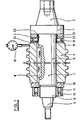
- a mandrel 1 which in the example shown in FIG. 1 has no axially continuous bore, is provided at one end with a first cone 2 for receiving in a machine tool spindle (not shown).
- a collar 7 is provided between a cylindrical part 6 of the mandrel receiving a hob 5 and said first cone. The hob is secured with a feather key 8 against twisting on the mandrel.
- the mandrel 1 is provided with a second cone 3 for rotatable mounting in a support bearing of the machine, not shown.
- the devices required for tensioning and driving the mandrel need not be discussed here since they are of no importance for the invention.
- a thread 9 is provided on the mandrel 1 between the cylindrical part 6 and the second cone 3 for a clamping nut 10, which bears against the hob 5 via one or more washers 15.
- the nut is provided with several, for example six, clamping screws 11, which are evenly distributed on a bolt circle and which can act eccentrically and axially on the hob 5.
- an adjusting ring 20 is provided between the hob 5 and the collar 7. Its inside diameter 24 is slight, i.e. a few tenths of a millimeter larger than the outer diameter 4 of the cylindrical part 6.
- the two side surfaces of the adjusting ring 20 rest on the milling cutter 5 and the collar 7.
- the setting ring is provided with several, for example 4 or 6, threaded bores evenly distributed over its circumference. Set screws 21 are screwed into this thread, which - bridging the radial distance 22 between the adjusting ring 20 and the cylindrical part 6 of the mandrel 1 - abut the mandrel.
- the hob is set as follows.
- the milling cutter 5 is pushed onto the mandrel 1 until it lies against the collar 7 via the adjusting ring 20.
- the clamping nut 10 is screwed on until it lies firmly against the milling cutter 5. Because the end faces of the milling cutter or the end faces of the clamping nut can have an impact, and because the threads of the mandrel and nut have play, and the nut can radially shift in the order of magnitude of this play and can be tilted due to the flank angle of the thread , the mother lies against the cutter on one side. Due to the uneven contact of the nut, the fibers of the mandrel on one side of the neutral fiber are stretched more than on the other, which has the effect of the cutter beating.
- the impact can be measured with a dial gauge 12 or the like on control seats 13 located on both sides of the milling cutter.
- the impact can be largely eliminated by appropriately tightening one or more tensioning screws 11 because this also stretches the fibers of the mandrel on the other side of the neutral fiber.
- This blow can be eliminated with the adjusting ring 20. If one assumes that the right lower edge of the milling cutter 5 brings the greatest dial gauge deflection, then the opposite set screw 21, i.e.
- the upper one is screwed in further while simultaneously unscrewing the lower set screw 21 lying in the area of the largest dial gauge deflection Adjusting ring 20 is pressed upwards and takes the milling cutter 5 with it through the friction on its contact surface.
- This setting of the milling cutter into an impact-free position is expediently carried out by alternately tightening the clamping nut 10 and tightening or loosening the clamping screws 11 and set screws 21.
- this elastic ring is an O-ring held in an annular groove, which easily withstands the deformation forced upon it by the setting ring.
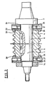
- a normal nut 14 is used instead of the clamping nut 10 provided with clamping screws, the installation of two adjusting rings is recommended, one on each side of the milling cutter.
- another type of adjusting ring is shown, which can be used just as well in the example according to FIG. 1 as the one shown there in the example according to FIG. 2.
- the adjusting rings are designated by 25, their inside diameter is again slightly larger than the outside diameter of the mandrel.
- An elastic ring is not necessary since the setting rings are centered on the control seat 13 of the milling cutter via the inner diameter 28 of annular projections 26.
- a plurality of adjusting screws 27 are provided in the setting rings 25, which are tightened and loosened accordingly.
- the position of the milling cutter in relation to the mandrel is also changed via the lugs 26.
- This solution has the advantage of being independent of the friction.
- FIG. 3 A variant of the setting ring 25 is shown in FIG. 3 with the setting ring 30.
- the setting ring 30 is therefore only pre-centered via an annular extension 31.
- clamping screws 32 are also provided in the area of the extension 31, with which the setting ring is clamped on the control seat 13 or on an additional collar.
- an inner centering is also possible.
- the adjusting ring is designated 35. With an annular, cylindrically limited extension 36, it is centered in a corresponding recess 37 in the milling cutter 5.
- the approach can also have a conical outer surface 38 (FIG. 5) and engage in a correspondingly shaped recess 39 of the tool.
- FIGS. 6 and 7. A ring 40 with an approximately T-shaped profile is divided into several, preferably 4 or 6, segments 41.
- the sections 42, 43 corresponding to the two arms of the T at least partially grip over the control seat 13 of the milling cutter 5 and over the collar 7, the section 44 corresponding to the trunk of the T lies laterally on the collar 7 and on the milling cutter 5, as in the previously described setting rings at.
- the section 42 lies on the control seat 13 over two inclined flat pressure surfaces 45.
- set screws 46 are used which rest with their heads on the section 43 and are screwed into the collar 7.
- the milling cutter 5 is adjusted by loosening or tightening the screws 46 appropriately, but in the opposite sense to that of the adjusting rings. If, analogously to FIG. 1, it is assumed that the lower right edge of the milling cutter 5 again causes the largest dial gauge deflection, then the opposite adjusting screw 46 is loosened and the lower adjusting screw, which is located in the area of the largest dial gauge deflection, is not shown in FIG Segment is approached to the mandrel and taken over the pressure surfaces of the milling cutters until the upper segment is again in contact with the screw head.
- This process - as with the setting rings 20, 25, 30, 35 - may be with different opposing set screws or repeated several times until the milling cutter is free of knocks.
- the set screws 21, 46 can be commercially available screws. For fine adjustment, however, screws with a fine thread are more advantageous. It is also important that the screws remain screwed in after the tool has been set in order to prevent the tool from being adjusted under the cutting pressure.
Claims (8)
Applications Claiming Priority (2)
| Application Number | Priority Date | Filing Date | Title |
|---|---|---|---|
| DE7916368U | 1979-06-07 | ||
| DE19797916368U DE7916368U1 (de) | 1979-06-07 | 1979-06-07 | Werkzeugaufnahme, insbesondere fuer das werkzeug einer waelzfraesmaschine |
Publications (2)
| Publication Number | Publication Date |
|---|---|
| EP0020864A1 EP0020864A1 (fr) | 1981-01-07 |
| EP0020864B1 true EP0020864B1 (fr) | 1983-06-22 |
Family
ID=6704686
Family Applications (1)
| Application Number | Title | Priority Date | Filing Date |
|---|---|---|---|
| EP80101407A Expired EP0020864B1 (fr) | 1979-06-07 | 1980-03-18 | Porte-outil, en particulier pour l'outil d'une fraise-mère |
Country Status (2)
| Country | Link |
|---|---|
| EP (1) | EP0020864B1 (fr) |
| DE (2) | DE7916368U1 (fr) |
Families Citing this family (9)
| Publication number | Priority date | Publication date | Assignee | Title |
|---|---|---|---|---|
| DE19860403B4 (de) * | 1998-12-28 | 2004-03-25 | Wilhelm Fette Gmbh | Anordnung aus Wälzfräskörper und Aufnahmedorn |
| JP5374164B2 (ja) * | 2009-01-08 | 2013-12-25 | 三菱重工業株式会社 | 工具 |
| CN102126054B (zh) * | 2011-03-15 | 2012-05-30 | 杭州风正电子科技有限公司 | 批量加工片齿轮的顶针芯轴 |
| CN102319930B (zh) * | 2011-08-18 | 2013-06-05 | 浙江大学 | 一种加工轮辐型薄片齿轮的夹具及使用方法 |
| EP2712694B1 (fr) * | 2012-09-28 | 2017-03-15 | WFL Millturn Technologies GmbH & Co. KG | Support d'outil pour une fraise-mère développante dans un type d'alésage |
| CN104043875A (zh) * | 2014-04-29 | 2014-09-17 | 浙江博雷重型机床制造有限公司 | 一种用于铣削齿条齿形的铣刀装置 |
| CN108481089B (zh) * | 2018-04-20 | 2019-01-11 | 徐州兰贵机械科技有限公司 | 一种机械制造中的过程检测装置 |
| CN111842980B (zh) * | 2020-08-07 | 2021-03-26 | 浙江沪龙科技股份有限公司 | 一种伺服电机转动配件制造加工工艺 |
| CN116480851B (zh) * | 2023-06-15 | 2023-10-27 | 江苏兆通重型装备有限公司 | 一种带有调节功能的lng船用管道支架 |
Family Cites Families (8)
| Publication number | Priority date | Publication date | Assignee | Title |
|---|---|---|---|---|
| US2577042A (en) * | 1951-02-24 | 1951-12-04 | Speicher Elmer | Truing and balancing device for face type diamond grinding wheels |
| US2841929A (en) * | 1956-12-26 | 1958-07-08 | Super Cut | Truing device for peripheral type grinding wheels |
| CH412526A (de) * | 1963-02-12 | 1966-04-30 | Albert Schrem Fa | Hydraulisches Spannelement |
| CH412519A (de) * | 1964-01-29 | 1966-04-30 | Koepfer & Soehne Gmbh Jos | Ausgleichsscheibe für Spanndorne |
| DE1303663B (fr) * | 1964-02-04 | 1972-05-25 | ||
| DE6601767U (de) * | 1966-06-16 | 1969-04-03 | Albert Fieseler | Aufspanndorne |
| DE1800769A1 (de) * | 1968-10-03 | 1970-05-27 | Hurth Masch Zahnrad Carl | Spanneinrichtung fuer Werkzeuge,insbesondere Waelzfraeser |
| JPS4862490A (fr) * | 1971-08-06 | 1973-08-31 |
-
1979
- 1979-06-07 DE DE19797916368U patent/DE7916368U1/de not_active Expired
-
1980
- 1980-03-18 DE DE8080101407T patent/DE3063823D1/de not_active Expired
- 1980-03-18 EP EP80101407A patent/EP0020864B1/fr not_active Expired
Also Published As
| Publication number | Publication date |
|---|---|
| DE3063823D1 (en) | 1983-07-28 |
| DE7916368U1 (de) | 1981-02-12 |
| EP0020864A1 (fr) | 1981-01-07 |
Similar Documents
| Publication | Publication Date | Title |
|---|---|---|
| EP0111092B1 (fr) | Dispositif d'accouplement | |
| EP0433925B1 (fr) | Dispositif de serrage hydraulique | |
| EP0312951A2 (fr) | Dispositif de serrage | |
| DE1938448B2 (de) | Gewindering | |
| EP0295315A1 (fr) | Assemblage d'outil | |
| EP0020864B1 (fr) | Porte-outil, en particulier pour l'outil d'une fraise-mère | |
| DE1303663B (fr) | ||
| DE3422000C2 (fr) | ||
| EP0630721B1 (fr) | Dispositif de serrage hydraulique | |
| DE3923131A1 (de) | Befestigungselement, insbesondere fuer eine kugel-gewindespindel | |
| EP0106087B1 (fr) | Outil combiné | |
| EP0275923A2 (fr) | Dispositif de serrage de pièces | |
| DE3410563C2 (de) | Spannvorrichtung für Werkzeuge od.dgl. | |
| DE2150467A1 (de) | Anordnung zum loesbaren verbinden zweier teile unter toleranzausgleich | |
| DE2525103A1 (de) | Hohlspindelanschlag | |
| EP0153560A2 (fr) | Dispositif de serrage | |
| DE2145524C3 (de) | Justiereinrichtung für Werkzeugmaschinen | |
| CH270608A (de) | Vorrichtung zum Einstellen der Distanz zweier Fräser, auf einem Fräserdorn. | |
| DE3509161C2 (fr) | ||
| EP0427967B1 (fr) | Palier avec dispositif de serrage pour un anneau de réglage | |
| DE2212005B1 (de) | Spannsatz in Doppelausführung mit konischen Elementen zur Nabenbefestigung | |
| CH412519A (de) | Ausgleichsscheibe für Spanndorne | |
| DE2444104C3 (de) | Spannsatz zum kraftschlüssigen Verbinden einer Welle mit einem dazu konzentrisch angeordneten Bauteil | |
| CH446013A (de) | Schnellspannfutter | |
| DE943286C (de) | Vorrichtung zum Zentrieren der Pressduesen von Ummantelungspressen fuer Schweissstaebe |
Legal Events
| Date | Code | Title | Description |
|---|---|---|---|
| PUAI | Public reference made under article 153(3) epc to a published international application that has entered the european phase |
Free format text: ORIGINAL CODE: 0009012 |
|
| AK | Designated contracting states |
Designated state(s): DE FR GB IT |
|
| ITCL | It: translation for ep claims filed |
Representative=s name: BARZANO' E ZANARDO ROMA S.P.A. |
|
| 17P | Request for examination filed |
Effective date: 19810515 |
|
| RAP1 | Party data changed (applicant data changed or rights of an application transferred) |
Owner name: HURTH, CARL MASCHINEN- UND ZAHNRADFABRIK GMBH & CO |
|
| ITF | It: translation for a ep patent filed |
Owner name: BARZANO' E ZANARDO ROMA S.P.A. |
|
| GRAA | (expected) grant |
Free format text: ORIGINAL CODE: 0009210 |
|
| AK | Designated contracting states |
Designated state(s): DE FR GB IT |
|
| REF | Corresponds to: |
Ref document number: 3063823 Country of ref document: DE Date of ref document: 19830728 |
|
| ET | Fr: translation filed | ||
| PLBE | No opposition filed within time limit |
Free format text: ORIGINAL CODE: 0009261 |
|
| STAA | Information on the status of an ep patent application or granted ep patent |
Free format text: STATUS: NO OPPOSITION FILED WITHIN TIME LIMIT |
|
| 26N | No opposition filed | ||
| PGFP | Annual fee paid to national office [announced via postgrant information from national office to epo] |
Ref country code: DE Payment date: 19890306 Year of fee payment: 10 |
|
| PGFP | Annual fee paid to national office [announced via postgrant information from national office to epo] |
Ref country code: FR Payment date: 19900329 Year of fee payment: 11 |
|
| ITTA | It: last paid annual fee | ||
| PGFP | Annual fee paid to national office [announced via postgrant information from national office to epo] |
Ref country code: GB Payment date: 19900331 Year of fee payment: 11 |
|
| PG25 | Lapsed in a contracting state [announced via postgrant information from national office to epo] |
Ref country code: DE Effective date: 19901201 |
|
| PG25 | Lapsed in a contracting state [announced via postgrant information from national office to epo] |
Ref country code: GB Effective date: 19910318 |
|
| GBPC | Gb: european patent ceased through non-payment of renewal fee | ||
| PG25 | Lapsed in a contracting state [announced via postgrant information from national office to epo] |
Ref country code: FR Effective date: 19911129 |
|
| REG | Reference to a national code |
Ref country code: FR Ref legal event code: ST |