EP0020864B1 - Tool holding device, particularly for a hobbing machine tool - Google Patents
Tool holding device, particularly for a hobbing machine tool Download PDFInfo
- Publication number
- EP0020864B1 EP0020864B1 EP80101407A EP80101407A EP0020864B1 EP 0020864 B1 EP0020864 B1 EP 0020864B1 EP 80101407 A EP80101407 A EP 80101407A EP 80101407 A EP80101407 A EP 80101407A EP 0020864 B1 EP0020864 B1 EP 0020864B1
- Authority
- EP
- European Patent Office
- Prior art keywords
- tool
- ring
- arbor
- rings
- collar
- Prior art date
- Legal status (The legal status is an assumption and is not a legal conclusion. Google has not performed a legal analysis and makes no representation as to the accuracy of the status listed.)
- Expired
Links
Images

Classifications
-
- B—PERFORMING OPERATIONS; TRANSPORTING
- B23—MACHINE TOOLS; METAL-WORKING NOT OTHERWISE PROVIDED FOR
- B23F—MAKING GEARS OR TOOTHED RACKS
- B23F23/00—Accessories or equipment combined with or arranged in, or specially designed to form part of, gear-cutting machines
- B23F23/12—Other devices, e.g. tool holders; Checking devices for controlling workpieces in machines for manufacturing gear teeth
- B23F23/1206—Tool mountings
Definitions
- the invention relates to a tool holder, in particular for the tool (milling cutter) of a hobbing machine, with a mandrel, which is formed at both ends in a suitable manner for centering and clamping in the machine tool spindle and in a support bearing, e.g. is provided with cones, and which for axially clamping the tool has a collar on one side of the tool and a clamping nut on the other side of the tool.
- German utility model 76 16 406 it is known to use a clamping nut which, on the side facing the tool, has an annular piston projecting axially from the nut, which closes a cylinder space containing a liquid or plastic mass.
- the volume of the cylinder space can be changed from the outside, so that the ring piston can be pressed against the tool regardless of the nut to be loosely tightened, where it rests with its entire ring surface. Clamping of the tool is therefore largely, but not entirely impossible.
- this device can be used to counteract the radial displacement of the nut and to a small extent a deflection of the mandrel , however, it is not possible to align the tool with the mandrel.
- the invention is based on the object of a device for impact-free receiving of the tool, in particular a hob cutter of a gear hobbing machine.
- This object is achieved with the characterizing feature of claim 1.
- the ring can have a rectangular cross section.
- the tool is also adjusted radially when the ring is adjusted by means of the radially arranged screws.
- Such a receptacle is preferably used where the clamping nut is already provided with devices for reducing the radial runout. Where this is not the case, the task can be solved with the characterizing feature of claim 2.
- the invention is developed with the characterizing feature of claim 3.
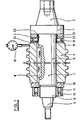
- a mandrel 1 which in the example shown in FIG. 1 has no axially continuous bore, is provided at one end with a first cone 2 for receiving in a machine tool spindle (not shown).
- a collar 7 is provided between a cylindrical part 6 of the mandrel receiving a hob 5 and said first cone. The hob is secured with a feather key 8 against twisting on the mandrel.
- the mandrel 1 is provided with a second cone 3 for rotatable mounting in a support bearing of the machine, not shown.
- the devices required for tensioning and driving the mandrel need not be discussed here since they are of no importance for the invention.
- a thread 9 is provided on the mandrel 1 between the cylindrical part 6 and the second cone 3 for a clamping nut 10, which bears against the hob 5 via one or more washers 15.
- the nut is provided with several, for example six, clamping screws 11, which are evenly distributed on a bolt circle and which can act eccentrically and axially on the hob 5.
- an adjusting ring 20 is provided between the hob 5 and the collar 7. Its inside diameter 24 is slight, i.e. a few tenths of a millimeter larger than the outer diameter 4 of the cylindrical part 6.
- the two side surfaces of the adjusting ring 20 rest on the milling cutter 5 and the collar 7.
- the setting ring is provided with several, for example 4 or 6, threaded bores evenly distributed over its circumference. Set screws 21 are screwed into this thread, which - bridging the radial distance 22 between the adjusting ring 20 and the cylindrical part 6 of the mandrel 1 - abut the mandrel.
- the hob is set as follows.
- the milling cutter 5 is pushed onto the mandrel 1 until it lies against the collar 7 via the adjusting ring 20.
- the clamping nut 10 is screwed on until it lies firmly against the milling cutter 5. Because the end faces of the milling cutter or the end faces of the clamping nut can have an impact, and because the threads of the mandrel and nut have play, and the nut can radially shift in the order of magnitude of this play and can be tilted due to the flank angle of the thread , the mother lies against the cutter on one side. Due to the uneven contact of the nut, the fibers of the mandrel on one side of the neutral fiber are stretched more than on the other, which has the effect of the cutter beating.
- the impact can be measured with a dial gauge 12 or the like on control seats 13 located on both sides of the milling cutter.
- the impact can be largely eliminated by appropriately tightening one or more tensioning screws 11 because this also stretches the fibers of the mandrel on the other side of the neutral fiber.
- This blow can be eliminated with the adjusting ring 20. If one assumes that the right lower edge of the milling cutter 5 brings the greatest dial gauge deflection, then the opposite set screw 21, i.e.
- the upper one is screwed in further while simultaneously unscrewing the lower set screw 21 lying in the area of the largest dial gauge deflection Adjusting ring 20 is pressed upwards and takes the milling cutter 5 with it through the friction on its contact surface.
- This setting of the milling cutter into an impact-free position is expediently carried out by alternately tightening the clamping nut 10 and tightening or loosening the clamping screws 11 and set screws 21.
- this elastic ring is an O-ring held in an annular groove, which easily withstands the deformation forced upon it by the setting ring.
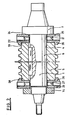
- a normal nut 14 is used instead of the clamping nut 10 provided with clamping screws, the installation of two adjusting rings is recommended, one on each side of the milling cutter.
- another type of adjusting ring is shown, which can be used just as well in the example according to FIG. 1 as the one shown there in the example according to FIG. 2.
- the adjusting rings are designated by 25, their inside diameter is again slightly larger than the outside diameter of the mandrel.
- An elastic ring is not necessary since the setting rings are centered on the control seat 13 of the milling cutter via the inner diameter 28 of annular projections 26.
- a plurality of adjusting screws 27 are provided in the setting rings 25, which are tightened and loosened accordingly.
- the position of the milling cutter in relation to the mandrel is also changed via the lugs 26.
- This solution has the advantage of being independent of the friction.
- FIG. 3 A variant of the setting ring 25 is shown in FIG. 3 with the setting ring 30.
- the setting ring 30 is therefore only pre-centered via an annular extension 31.
- clamping screws 32 are also provided in the area of the extension 31, with which the setting ring is clamped on the control seat 13 or on an additional collar.
- an inner centering is also possible.
- the adjusting ring is designated 35. With an annular, cylindrically limited extension 36, it is centered in a corresponding recess 37 in the milling cutter 5.
- the approach can also have a conical outer surface 38 (FIG. 5) and engage in a correspondingly shaped recess 39 of the tool.
- FIGS. 6 and 7. A ring 40 with an approximately T-shaped profile is divided into several, preferably 4 or 6, segments 41.
- the sections 42, 43 corresponding to the two arms of the T at least partially grip over the control seat 13 of the milling cutter 5 and over the collar 7, the section 44 corresponding to the trunk of the T lies laterally on the collar 7 and on the milling cutter 5, as in the previously described setting rings at.
- the section 42 lies on the control seat 13 over two inclined flat pressure surfaces 45.
- set screws 46 are used which rest with their heads on the section 43 and are screwed into the collar 7.
- the milling cutter 5 is adjusted by loosening or tightening the screws 46 appropriately, but in the opposite sense to that of the adjusting rings. If, analogously to FIG. 1, it is assumed that the lower right edge of the milling cutter 5 again causes the largest dial gauge deflection, then the opposite adjusting screw 46 is loosened and the lower adjusting screw, which is located in the area of the largest dial gauge deflection, is not shown in FIG Segment is approached to the mandrel and taken over the pressure surfaces of the milling cutters until the upper segment is again in contact with the screw head.
- This process - as with the setting rings 20, 25, 30, 35 - may be with different opposing set screws or repeated several times until the milling cutter is free of knocks.
- the set screws 21, 46 can be commercially available screws. For fine adjustment, however, screws with a fine thread are more advantageous. It is also important that the screws remain screwed in after the tool has been set in order to prevent the tool from being adjusted under the cutting pressure.
Description
Die Erfindung bezieht sich auf eine Werkzeugaufnahme, insbesondere für das Werkzeug (Fräser) einer Wälzfräsmaschine, mit einem Spanndorn, der an beiden Enden jeweils zum Zentrieren und Spannen in der Werkzeugmaschinenspindel und in einem Stützlager in geeigneter Weise ausgebildet, z.B. mit Konen versehen, ist, und der zum axialen Spannen des Werkzeugs einen Bund auf der einen Seite des Werkzeugs und eine Spannmutter auf der anderen Seite des Werkzeugs aufweist.The invention relates to a tool holder, in particular for the tool (milling cutter) of a hobbing machine, with a mandrel, which is formed at both ends in a suitable manner for centering and clamping in the machine tool spindle and in a support bearing, e.g. is provided with cones, and which for axially clamping the tool has a collar on one side of the tool and a clamping nut on the other side of the tool.
Es ist üblich, Werkstücke oder Werkzeuge auf einem Spanndorn aufzunehmen und mit einer Mutter gegen einen Bund od. dgl. zu ziehen und zu spannen. Auf diese Weise werden beispielsweise Abwälzfräser gespannt. Da die Gewinde solcher Dorne nie ganz genau laufen, die Muttern im allgemeinen nicht genau plan sind und die Gewinde von Dorn und Mutter immer Spiel aufweisen, so daß sich die Mutter beim Anziehen im Maße dieses Spiels radial verschieben und dadurch verkanten kann, wird auf das zu spannende Stück, beispielsweise auf den Abwälzfräser, ein einseitiger Druck ausgeübt, der zu einem Radialschlag oder Rundlauffehler des Fräsers führt. Je nachdem, welche Passung zwischen dem Dom und dem Fräser vorhanden ist, kann dieser Schlag bis zu 0,02 mm und mehr betragen. Er kann aber auch bei einem ohne Spiel auf dem Dorn sitzenden Fräser vorhanden sein, da die Fasern des Dornes durch den einseitigen Druck ungleich gedehnt werden, so daß der Dorn krummgezogen wird.It is common to hold workpieces or tools on a mandrel and to pull or clamp them against a collar or the like with a nut. In this way, hob cutters are clamped, for example. Since the threads of such mandrels never run exactly, the nuts are generally not exactly flat and the threads of the mandrel and nut always have play, so that the nut can move radially when tightened to the extent of this play and thereby tilt, which is why Too exciting pieces, for example on the hob, exerted one-sided pressure, which leads to a radial runout or runout of the milling cutter. Depending on the fit between the dome and the milling cutter, this impact can be up to 0.02 mm and more. However, it can also be present in a milling cutter seated on the mandrel without play, since the fibers of the mandrel are stretched unevenly by the one-sided pressure, so that the mandrel is bent.
Zur Verringerung des Schlages sind schon verschiedene Einrichtungen vorgeschlagen worden. Nach dem US-Patent 3 249 015 weist die Mutter auf einem Lochkreis Gewindebohrungen mit Schrauben auf, von denen je nach Lage und Größe des Radialschlages wenigstens eine mehr oder weniger stark angezogen und gegen den Fräser gedrückt wird. Dabei wird der Dorn einseitig gedehnt, so daß der Schlag weitgehend beseitigt werden kann.Various devices have already been proposed to reduce the impact. According to US Pat. No. 3,249,015, the nut has threaded bores with screws on a bolt circle, at least one of which, depending on the position and size of the radial runout, is tightened to a greater or lesser extent and pressed against the milling cutter. The mandrel is stretched on one side so that the blow can be largely eliminated.
Vom deutschen Gebrauchsmuster 76 16 406 ist es bekannt, eine Spannmutter zu verwenden, die auf der dem Werkzeug zugewendeten Seite einen axial aus der Mutter herausragenden Ringkolben aufweist, der einen eine Flüssigkeit oder plastische Masse enthaltenden Zylinderraum verschließt. Das Volumen des Zylinderraumes ist von außen veränderbar, so daß der Ringkolben unabhängig von der nur lose anzuziehenden Mutter gegen das Werkzeug gepreßt werden kann, wo er mit seiner ganzen Ringfläche anliegt. Ein Verspannen des Werkzeugs ist damit weitgehend, aber nicht völlig ausgeschlossen.From German utility model 76 16 406 it is known to use a clamping nut which, on the side facing the tool, has an annular piston projecting axially from the nut, which closes a cylinder space containing a liquid or plastic mass. The volume of the cylinder space can be changed from the outside, so that the ring piston can be pressed against the tool regardless of the nut to be loosely tightened, where it rests with its entire ring surface. Clamping of the tool is therefore largely, but not entirely impossible.
Es ist auch schon vorgeschlagen worden (Deutsches Gebrauchsmuster 6 601 767), zwischen dem Werkzeug und dem Bund od. dgl. und/oder zwischen dem Werkzeug und der * Mutter auf dem Spanndorn ringförmige Halteelemente mit L-förmigem Querschnitt anzubringen, die mit ihrer einen, ebenen Stirnfläche am Werkzeug anliegen und auf deren gegenüberliegendem Ansatz ein durch Schrauben radial verstellbarer Ring angeordnet ist, der sich mit seiner einen, ebenen Stirnfläche am Bund oder an der Mutter und mit seiner anderen, als balliger Außenkegel geformten Stirnfläche an der anderen, hohlkegelig geformten Stirnfläche des Halteelementes abstützt. Da der radial verstellbare Ring zwischen dem Halteelement und dem Bund od. dgl. und/oder der Mutter angeordnet ist und die Schrauben mit dem Halteelement zusammenwirken, kann mit dieser Einrichtung zwar dem radialen Verschieben der Mutter und in geringem Maße einer Durchbiegung des Spanndornes entgegengewirkt werden, ein Ausrichten des Werkzeugs gegenüber dem Spanndorn ist dagegen nicht möglich.It has also been proposed (Deutsches Utility Model 6 601 767) to attach ring-shaped holding elements with an L-shaped cross section between the tool and the collar or the like and / or between the tool and the * nut on the mandrel, with one of them , lie flat end face on the tool and on the opposite approach a radially adjustable ring is arranged by screws, which is with its one, flat end face on the collar or on the nut and with its other, shaped as a spherical outer cone on the other, hollow cone shaped End face of the holding element supports. Since the radially adjustable ring is arranged between the holding element and the collar or the like and / or the nut and the screws cooperate with the holding element, this device can be used to counteract the radial displacement of the nut and to a small extent a deflection of the mandrel , however, it is not possible to align the tool with the mandrel.
In vielen Fällen ist es erforderlich, die Rundlaufgenauigkeit noch weiter zu erhöhen als dies mit den bekannten Einrichtungen möglich ist.In many cases it is necessary to increase the concentricity even further than is possible with the known devices.
Der Erfindung liegt als Aufgabe eine Vorrichtung zum schlagfreien Aufnehmen des Werkzeugs, insbesondere eines Abwälzfräsers einer Zahnrad-Wälzfräsmaschine, zugrunde. Diese Aufgabe wird mit dem kennzeichnenden Merkmal des Anspruchs 1 gelöst. In der einfachsten Ausführung kann der Ring rechteckigen Querschnitt haben. Infolge der Reibung an der Berührfläche zwischen dem Werkzeug und dem Ring wird beim Verstellen des Ringes mittels der radial angeordneten Schrauben auch das Werkzeug radial verstellt. Eine derartige Aufnahme ist vorzugsweise dort anzuwenden, wo die Spannmutter schon mit Einrichtungen zur Verminderung des Radialschlages versehen ist. Wo das nicht der Fall ist, kann die Aufgabe mit dem kennzeichnenden Merkmal des Anspruchs 2 gelöst werden. Um den Ring in seiner Ausgangslage einfach zentrieren zu können, wird die Erfindung mit dem kennzeichnenden Merkmal des Anspruchs 3 weitergebildet. Eine von der Reibung unabhängige Verstellung des Werkzeuges wird erreicht, wenn der Ring auf oder in dem Werkzeug zentriert wird, wie das in verschiedenen Lösungen nach den kennzeichnenden Merkmalen der Ansprüche 4 bis 7 möglich ist. Eine sehr zweckmäßige Zentrierung läßt sich auch mit einem in mehrere Segmente unterteilten Ring erreichen (Anspruch 8).The invention is based on the object of a device for impact-free receiving of the tool, in particular a hob cutter of a gear hobbing machine. This object is achieved with the characterizing feature of
Die Erfindung wird nachstehend anhand der Figuren 1 bis 7 beschrieben.
Figur 1 zeigt eine Werkzeugaufnahme nach der Erfindung;Figur 2 zeigt eine andere Ausführung einer Werkzeugaufnahme nach der Erfindung;Figuren Figuren 6 und 7 zeigen eine weitere Variante im Längs- und im Querschnitt.
- Figure 1 shows a tool holder according to the invention;
- Figure 2 shows another embodiment of a tool holder according to the invention;
- Figures 3, 4 and 5 show variants of the radially adjustable element in longitudinal section;
- Figures 6 and 7 show a further variant in longitudinal and cross-section.
Ein Spanndorn 1, der bei dem in Figur 1 gezeigten Beispiel keine axial durchgehende Bohrung aufweist, ist an einem Ende mit einem ersten Konus 2 zur Aufnahme in einer nicht gezeichneten Werkzeugmaschinenspindel versehen. Zwischen einem einen Wälzfräser 5 aufnehmenden zylinderischen Teil 6 des Spanndornes und dem besagten ersten Konus ist ein Bund 7 vorgesehen. Der Wälzfräser ist mit einer Paßfeder 8 gegen Verdrehen auf dem Spanndorn gesichert. Am anderen Ende ist der Spanndorn 1 mit einem zweiten Konus 3 versehen zur drehbaren Aufnahme in einem nicht gezeichneten Stützlager der Maschine. Auf die zum Spannen und zum Antreiben des Spanndornes erforderlichen Einrichtungen braucht hier nicht eingegangen zu werden, da sie für die Erfindung ohne Bedeutung sind.A
Auf dem Spanndorn 1 ist zwischen dem zylinderischen Teil 6 und dem zweiten Konus 3 ein Gewinde 9 vorgesehen für eine Spannmutter 10, die über eine oder mehrere Scheiben 15 am Wälzfräser 5 anliegt. Die Mutter ist mit mehreren, beispielsweise sechs, gleichmäßig auf einem Lochkreis verteilten Spannschrauben 11 versehen, die exzentrisch und axial auf den Wälzfräser 5 einwirken können. Auf der anderen Seite ist zwischen dem Wälzfräser 5 und dem Bund 7 ein Einstellring 20 vorgesehen. Sein Innendurchmesser 24 ist geringfügig, d.h. wenige Zehntelmillimeter größer als der Außendurchmesser 4 des zylinderischen Teiles 6. Die beiden Seitenflächen des Einstellringes 20 liegen am Fräser 5 und am Bund 7 an. Der Einstellring ist mit mehreren, beispielsweise 4 oder 6, gleichmäßig auf seinem Umfang verteilten Gewindebohrungen versehen. In dieses Gewinde sind Stellschrauben 21 eingeschraubt, die - den radialen Abstand 22 zwischen dem Einstellring 20 und dem zylinderischen Teil 6 des Spanndornes 1 überbrückend - am Spanndorn anstehen.A
Das Einstellen des Wälzfräsers geht folgendermaßen vor sich. Der Fräser 5 wird auf den Spanndorn 1 aufgesteckt, bis er über den Einstellring 20 am Bund 7 anliegt. Die Spannmutter 10 wird aufgeschraubt, bis sie fest gegen den Fräser 5 anliegt. Dadurch, daß die Stirnseiten des Fräsers oder die Stirnseiten der Spannmutter einen Schlag haben können, und dadurch, daß die Gewinde von Dorn und Mutter Spiel haben, und sich die Mutter in der Größenordnung dieses Spiels radial verschieben und sich infolge des Flankenwinkels der Gewinde verkanten kann, legt sich die Mutter einseitig gegen den Fräser an. Durch die ungleiche Anlage der Mutter werden die Fasern des Spanndornes auf der einen Seite der neutralen Faser stärker gedehnt als auf der anderen, was sich als Schlag des Fräsers auswirkt. Das Messen des Schlages kann mit einer Meßuhr 12 oder dergleichen an beiderseits am Fräser befindlichen Kontrollsitzen 13 erfolgen. Durch entsprechendes Anziehen einer oder mehrerer Spannschrauben 11 kann der Schlag weitgehend beseitigt werden, weil dadurch auch die Fasern des Spanndornes auf der anderen Seite der neutralen Faser gedehnt werden. Es ist aber nicht auszuschließen, daß der Fräser wegen der Passungstoleranzen schief auf dem Spanndorn sitzt in der Art, daß auf der Seite der Spannmutter kein meßbarer Schlag mehr vorhanden ist, wohl aber auf der dem Bund zugewendeten Seite. Dieser Schlag kann mit dem Einstellring 20 beseitigt werden. Wenn man annimmt, daß die rechte untere Kante des Fräsers 5 den größten Meßuhrausschlag bringt, dann wird die gegenüberliegende Stellschraube 21, also die obere, weiter eingeschraubt unter gleichzeitigem entsprechendem Herausdrehen der unteren, im Bereich des größten Meßuhrausschlages liegenden, Stellschraube 21. Dadurch wird der Einstellring 20 nach oben gedrückt und nimmt über die Reibung an seiner Anlagefläche den Fräser 5 mit. Dieses Einstellen des Fräsers in eine schlagfreie Position geschieht zweckmäßigerweise durch abwechselndes schrittweises Anziehen der Spannmutter 10 und Anziehen bzw. Lösen der Spannschrauben 11 und Stellschrauben 21.The hob is set as follows. The
Damit sich der Einstellring 20 zu Beginn des Einstellvorganges in einer zentrischen Stellung gegenüber dem Spanndorn 5 befindet und nicht in seiner Bohrung 24 auf dem zylinderischen Teil 6 aufliegt, ist er über einen elastischen Ring 23 auf dem Spanndorn zentriert. Dieser elastische Ring ist im Ausführungsbeispiel ein in einer Ringnut gehaltener O-Ring, der der ihm beim Einstellen vom Einstellring aufgezwungenen Verformung ohne weiteres standhält.So that the
Wenn statt der mit Spannschrauben versehenen Spannmutter 10 eine normale Mutter 14 verwendet wird, empfiehlt sich der Einbau von zwei Einstellringen, zu jeder Seite des Fräsers einer. Bei dem in Figur 2 gezeigten Ausführungsbeispiel ist eine andere Art Einstellring dargestellt, der ebensogut beim Beispiel nach Figur 1 verwendet werden kann wie der dort gezeigte beim Beispiel nach Figur 2. Die Einstellringe sind mit 25 bezeichnet, Ihr Innendurchmesser ist wieder geringfügig größer als der Außendurchmesser des Spanndornes. Ein elastischer Ring ist nicht erforderlich, da die Einstellringe über die Innendurchmesser 28 von ringförmigen Ansätzen 26 auf dem Kontrollsitz 13 des Fräsers zentriert sind. Zum schlagfreien Einstellen des Fräsers sind in den Einstellringen 25 mehrere Stellschrauben 27 vorgesehen, die entsprechend angezogen und gelöst werden. Dabei wird die Lage des Fräsers gegenüber dem Dorn über die Ansätze 26 mit verändert. Diese Lösung hat den Vorteil, unabhängig von der Reibung zu sein.If a
Eine Variante zum Einstellring 25 ist in Figur 3 mit dem Einstellring 30 dargestellt. Eine spielfreie Zentrierung über den Ansatz 26 auf dem Kontrollsitz 13 erschwert den Zusammenbau und - mehr noch - den Ausbau des Fräsers. Der Einstellring 30 ist deshalb über einen ringförmigen Ansatz 31 nur vorzentriert. Zusätzlich zu den Stellschrauben 21 sind im Bereich des Ansatzes 31 noch Klemmschrauben 32 vorgesehen, mit denen der Einstellring auf dem Kontrollsitz 13 oder auf einem zusätzlichen Bund festgeklemmt wird. Statt der Zentrierung des Einstellringes außen auf dem Kontrollsitz 13 ist auch eine Innenzentrierung möglich. In Figur 4 ist der Einstellring mit 35 bezeichnet. Mit einem ringförmigen, zylinderisch begrenzten Ansatz 36 ist er in einer entsprechenden Ausnehmung 37 im Fräser 5 zentriert. Der Ansatz kann auch eine kegelige Mantelfläche 38 haben (Fig. 5) und in eine entsprechend geformte Ausnehmung 39 des Werkzeugs eingreifen.A variant of the setting
Ein weiteres Ausführungsbeispiel ist in Figur 6 und 7 gezeigt. Ein Ring 40 mit etwa T-förmigem Profil ist in mehrere, vorzugsweise 4 oder 6, Segmente 41 unterteilt. Die den beiden Armen des T entsprechenden Abschnitte 42, 43 greifen zumindest teilweise über den Kontrollsitz 13 des Fräsers 5 und über den Bund 7, der dem Stamm des T entsprechende Abschnitt 44 liegt wie bei den vorher beschriebenen Einstellringen seitlich am Bund 7 und am Fräser 5 an. Der Abschnitt 42 liegt über zwei zueinander geneigte ebene Druckflächen 45 auf dem Kontrollsitz 13 auf. Zum radialen Verstellen der Segmente 41 und gleichzeitig zum Halten dienen Stellschrauben 46, die mit ihrem Kopf auf dem Abschnitt 43 aufliegen und im Bund 7 eingeschraubt sind. Das Einstellen des Fräsers 5 erfolgt durch entsprechendes Lösen bzw. Nachziehen der Schrauben 46, aber im umgekehrten Sinne wie bei den Einstellringeri. Wenn man analog zur Figur 1 annimmt, daß wieder die rechte untere Kante des Fräsers 5 den größten Meßuhrausschlag bringt, dann wird die gegenüberliegende Stellschraube 46 gelöst und die untere, im Bereich des größten Meßuhrausschlages liegende, in Figur 6 nicht gezeigte Stellschraube nachgezogen, wobei das Segment dem Spanndorn genähert und über die Druckflächen der Fräser mitgenommen wird, bis das obere Segment wieder am Schraubenkopf anliegt. Dieser Vorgang muß - wie auch bei den Einstellringen 20, 25, 30, 35 - u.U. bei verschiedenen einander gegenüberliegenden Stellschrauben durchgeführt oder auch mehrmals wiederholt werden, bis der Fräser schlagfrei ist.Another exemplary embodiment is shown in FIGS. 6 and 7. A ring 40 with an approximately T-shaped profile is divided into several, preferably 4 or 6, segments 41. The sections 42, 43 corresponding to the two arms of the T at least partially grip over the
Die Stellschrauben 21, 46 können handelsübliche Schrauben sein. Für ein feinfühliges Einstellen sind aber Schrauben mit Feingewinde vorteilhafter. Wichtig ist noch, daß die Schrauben nach dem Einstellen des Werkzeugs eingeschraubt bleiben, um eine Verstellung des Werkzeugs unter dem Schnittdruck zu vermeiden.The set screws 21, 46 can be commercially available screws. For fine adjustment, however, screws with a fine thread are more advantageous. It is also important that the screws remain screwed in after the tool has been set in order to prevent the tool from being adjusted under the cutting pressure.
Claims (8)
Applications Claiming Priority (2)
| Application Number | Priority Date | Filing Date | Title |
|---|---|---|---|
| DE19797916368U DE7916368U1 (en) | 1979-06-07 | 1979-06-07 | TOOL HOLDER, IN PARTICULAR FOR THE TOOL OF A WALL MILLING MACHINE |
| DE7916368U | 1979-06-07 |
Publications (2)
| Publication Number | Publication Date |
|---|---|
| EP0020864A1 EP0020864A1 (en) | 1981-01-07 |
| EP0020864B1 true EP0020864B1 (en) | 1983-06-22 |
Family
ID=6704686
Family Applications (1)
| Application Number | Title | Priority Date | Filing Date |
|---|---|---|---|
| EP80101407A Expired EP0020864B1 (en) | 1979-06-07 | 1980-03-18 | Tool holding device, particularly for a hobbing machine tool |
Country Status (2)
| Country | Link |
|---|---|
| EP (1) | EP0020864B1 (en) |
| DE (2) | DE7916368U1 (en) |
Families Citing this family (9)
| Publication number | Priority date | Publication date | Assignee | Title |
|---|---|---|---|---|
| DE19860403B4 (en) * | 1998-12-28 | 2004-03-25 | Wilhelm Fette Gmbh | Arrangement of hobbing body and arbor |
| JP5374164B2 (en) * | 2009-01-08 | 2013-12-25 | 三菱重工業株式会社 | tool |
| CN102126054B (en) * | 2011-03-15 | 2012-05-30 | 杭州风正电子科技有限公司 | Ejector pin pivot for batch machining of sheet gears |
| CN102319930B (en) * | 2011-08-18 | 2013-06-05 | 浙江大学 | Fixture for machining spoke type web gears and usage thereof |
| EP2712694B1 (en) * | 2012-09-28 | 2017-03-15 | WFL Millturn Technologies GmbH & Co. KG | Tool holder for a hob in borehole design |
| CN104043875A (en) * | 2014-04-29 | 2014-09-17 | 浙江博雷重型机床制造有限公司 | Milling tool device for milling tooth profile of rack |
| CN108481089B (en) * | 2018-04-20 | 2019-01-11 | 徐州兰贵机械科技有限公司 | A kind of process detection device in machine-building |
| CN111842980B (en) * | 2020-08-07 | 2021-03-26 | 浙江沪龙科技股份有限公司 | Manufacturing and machining process for rotating accessories of servo motor |
| CN116480851B (en) * | 2023-06-15 | 2023-10-27 | 江苏兆通重型装备有限公司 | Marine pipeline support of LNG with regulatory function |
Family Cites Families (8)
| Publication number | Priority date | Publication date | Assignee | Title |
|---|---|---|---|---|
| US2577042A (en) * | 1951-02-24 | 1951-12-04 | Speicher Elmer | Truing and balancing device for face type diamond grinding wheels |
| US2841929A (en) * | 1956-12-26 | 1958-07-08 | Super Cut | Truing device for peripheral type grinding wheels |
| CH412526A (en) * | 1963-02-12 | 1966-04-30 | Albert Schrem Fa | Hydraulic clamping element |
| CH412519A (en) * | 1964-01-29 | 1966-04-30 | Koepfer & Soehne Gmbh Jos | Compensating washer for mandrels |
| DE1303663B (en) * | 1964-02-04 | 1972-05-25 | ||
| DE6601767U (en) * | 1966-06-16 | 1969-04-03 | Albert Fieseler | CLAMPING ARM |
| DE1800769A1 (en) * | 1968-10-03 | 1970-05-27 | Hurth Masch Zahnrad Carl | Clamping device for tools, especially hob cutters |
| JPS4862490A (en) * | 1971-08-06 | 1973-08-31 |
-
1979
- 1979-06-07 DE DE19797916368U patent/DE7916368U1/en not_active Expired
-
1980
- 1980-03-18 EP EP80101407A patent/EP0020864B1/en not_active Expired
- 1980-03-18 DE DE8080101407T patent/DE3063823D1/en not_active Expired
Also Published As
| Publication number | Publication date |
|---|---|
| DE7916368U1 (en) | 1981-02-12 |
| EP0020864A1 (en) | 1981-01-07 |
| DE3063823D1 (en) | 1983-07-28 |
Similar Documents
| Publication | Publication Date | Title |
|---|---|---|
| EP0111092B1 (en) | Coupling device | |
| EP0433925B1 (en) | Hydraulic clamping device | |
| EP0312951A2 (en) | Clamping device | |
| DE1938448B2 (en) | Threaded ring | |
| EP0295315A1 (en) | Tool assembly | |
| EP0020864B1 (en) | Tool holding device, particularly for a hobbing machine tool | |
| DE1303663B (en) | ||
| DE3422000C2 (en) | ||
| EP0630721B1 (en) | Hydraulic clamping device | |
| DE3923131A1 (en) | FASTENING ELEMENT, ESPECIALLY FOR A BALL SCREW | |
| DE3417641A1 (en) | HYDRAULIC TENSION ELEMENT WITH BALANCE | |
| EP0106087B1 (en) | Combination tool | |
| EP0275923A2 (en) | Clamping device for work pieces | |
| DE3410563C2 (en) | Clamping device for tools or the like. | |
| DE2150467A1 (en) | ARRANGEMENT FOR DETACHABLE CONNECTING TWO PARTS UNDER TOLERANCE COMPENSATION | |
| DE2525103A1 (en) | Lathe hollow spindle stop - incorporates conical part with tension screw and three jaws pressable against spindl inner wall | |
| EP0153560A2 (en) | Clamping device | |
| DE2145524C3 (en) | Adjustment device for machine tools | |
| CH270608A (en) | Device for setting the distance between two milling cutters on a milling cutter arbor. | |
| DE3509161C2 (en) | ||
| EP0427967B1 (en) | Bearing arrangement with a locking device for an adjusting ring | |
| DE2212005B1 (en) | Clamping set in double design with conical elements for hub attachment | |
| CH412519A (en) | Compensating washer for mandrels | |
| DE2444104C3 (en) | Clamping set for frictional connection of a shaft with a component arranged concentrically to it | |
| CH446013A (en) | Quick release chuck |
Legal Events
| Date | Code | Title | Description |
|---|---|---|---|
| PUAI | Public reference made under article 153(3) epc to a published international application that has entered the european phase |
Free format text: ORIGINAL CODE: 0009012 |
|
| AK | Designated contracting states |
Designated state(s): DE FR GB IT |
|
| ITCL | It: translation for ep claims filed |
Representative=s name: BARZANO' E ZANARDO ROMA S.P.A. |
|
| 17P | Request for examination filed |
Effective date: 19810515 |
|
| RAP1 | Party data changed (applicant data changed or rights of an application transferred) |
Owner name: HURTH, CARL MASCHINEN- UND ZAHNRADFABRIK GMBH & CO |
|
| ITF | It: translation for a ep patent filed |
Owner name: BARZANO' E ZANARDO ROMA S.P.A. |
|
| GRAA | (expected) grant |
Free format text: ORIGINAL CODE: 0009210 |
|
| AK | Designated contracting states |
Designated state(s): DE FR GB IT |
|
| REF | Corresponds to: |
Ref document number: 3063823 Country of ref document: DE Date of ref document: 19830728 |
|
| ET | Fr: translation filed | ||
| PLBE | No opposition filed within time limit |
Free format text: ORIGINAL CODE: 0009261 |
|
| STAA | Information on the status of an ep patent application or granted ep patent |
Free format text: STATUS: NO OPPOSITION FILED WITHIN TIME LIMIT |
|
| 26N | No opposition filed | ||
| PGFP | Annual fee paid to national office [announced via postgrant information from national office to epo] |
Ref country code: DE Payment date: 19890306 Year of fee payment: 10 |
|
| PGFP | Annual fee paid to national office [announced via postgrant information from national office to epo] |
Ref country code: FR Payment date: 19900329 Year of fee payment: 11 |
|
| ITTA | It: last paid annual fee | ||
| PGFP | Annual fee paid to national office [announced via postgrant information from national office to epo] |
Ref country code: GB Payment date: 19900331 Year of fee payment: 11 |
|
| PG25 | Lapsed in a contracting state [announced via postgrant information from national office to epo] |
Ref country code: DE Effective date: 19901201 |
|
| PG25 | Lapsed in a contracting state [announced via postgrant information from national office to epo] |
Ref country code: GB Effective date: 19910318 |
|
| GBPC | Gb: european patent ceased through non-payment of renewal fee | ||
| PG25 | Lapsed in a contracting state [announced via postgrant information from national office to epo] |
Ref country code: FR Effective date: 19911129 |
|
| REG | Reference to a national code |
Ref country code: FR Ref legal event code: ST |