EP0019655A1 - Dispositif pour la fixation temporaire d'éléments de raccord de tuyaux de drainage dans le béton lors de la coulée de la plaque de fond d'un lit filtrant - Google Patents
Dispositif pour la fixation temporaire d'éléments de raccord de tuyaux de drainage dans le béton lors de la coulée de la plaque de fond d'un lit filtrant Download PDFInfo
- Publication number
- EP0019655A1 EP0019655A1 EP79102988A EP79102988A EP0019655A1 EP 0019655 A1 EP0019655 A1 EP 0019655A1 EP 79102988 A EP79102988 A EP 79102988A EP 79102988 A EP79102988 A EP 79102988A EP 0019655 A1 EP0019655 A1 EP 0019655A1
- Authority
- EP
- European Patent Office
- Prior art keywords
- filter
- expansion
- formwork
- connecting elements
- collecting duct
- Prior art date
- Legal status (The legal status is an assumption and is not a legal conclusion. Google has not performed a legal analysis and makes no representation as to the accuracy of the status listed.)
- Granted
Links
- 238000005266 casting Methods 0.000 title 1
- XLYOFNOQVPJJNP-UHFFFAOYSA-N water Substances O XLYOFNOQVPJJNP-UHFFFAOYSA-N 0.000 claims abstract description 7
- 239000000706 filtrate Substances 0.000 claims abstract description 3
- 230000002441 reversible effect Effects 0.000 claims abstract description 3
- 238000009415 formwork Methods 0.000 claims description 20
- 229920001971 elastomer Polymers 0.000 claims description 4
- 239000000806 elastomer Substances 0.000 claims description 3
- 238000009416 shuttering Methods 0.000 abstract 2
- 238000004026 adhesive bonding Methods 0.000 description 2
- 238000003466 welding Methods 0.000 description 2
- 229910000831 Steel Inorganic materials 0.000 description 1
- 238000007654 immersion Methods 0.000 description 1
- 238000011065 in-situ storage Methods 0.000 description 1
- 238000009434 installation Methods 0.000 description 1
- 238000004519 manufacturing process Methods 0.000 description 1
- 230000002787 reinforcement Effects 0.000 description 1
- 238000003892 spreading Methods 0.000 description 1
- 239000010959 steel Substances 0.000 description 1
Images

Classifications
-
- B—PERFORMING OPERATIONS; TRANSPORTING
- B01—PHYSICAL OR CHEMICAL PROCESSES OR APPARATUS IN GENERAL
- B01D—SEPARATION
- B01D24/00—Filters comprising loose filtering material, i.e. filtering material without any binder between the individual particles or fibres thereof
- B01D24/001—Making filter elements not provided for elsewhere
-
- B—PERFORMING OPERATIONS; TRANSPORTING
- B01—PHYSICAL OR CHEMICAL PROCESSES OR APPARATUS IN GENERAL
- B01D—SEPARATION
- B01D24/00—Filters comprising loose filtering material, i.e. filtering material without any binder between the individual particles or fibres thereof
- B01D24/02—Filters comprising loose filtering material, i.e. filtering material without any binder between the individual particles or fibres thereof with the filter bed stationary during the filtration
- B01D24/20—Filters comprising loose filtering material, i.e. filtering material without any binder between the individual particles or fibres thereof with the filter bed stationary during the filtration the filtering material being provided in an open container
- B01D24/22—Downward filtration, the filter material being supported by pervious surfaces
Definitions
- the invention relates to a device for temporarily fixing connecting elements during their concreting into the bottom of a filter field of a filter system, in particular for water treatment, filter nozzles being provided in the filter field as passage elements for the filtered medium, which are lined up in a number of drainage pipes, which in turn arranged at least approximately parallel to one another in the area of the concrete bottom of the filter field and each connected via a connecting pipe to a collecting duct for the filtrate to be discharged, which is laid under the filter bottom.
- connecting elements For a new type of installation of the drainage pipes on the bottom of a filter field (P. 5425), connecting elements must be concreted into the filter base, through which openings in the filter base lead to an underlying collecting channel for the pure water.
- the drainage pipes covering the base of the filter base, which are prefabricated in the workshop, are inserted into these through-openings with the aid of connecting or immersion tubes attached to them after the filter base has been completed.
- the connecting elements In order to enable the assembly of the prefabricated drainage pipes, the connecting elements have to be arranged with relatively great accuracy at predetermined locations on the finished filter base.
- the present invention is therefore based on the object of providing a device with which a temporary fixing of the connecting elements in the manufacture of the filter base is made possible in a simple manner.
- This object is achieved by an impact-resistant formwork body which runs in the direction of the collecting duct and has support bolts for a reversibly expandable expansion body at a distance which corresponds to the distance of the drainage pipes to be installed, furthermore by expansion bodies placed on the support bolts and by means of individual, reversible expansion of the individual expansion bodies.
- At least approximately incompressible, barrel-shaped elastomers which are pressed together in the axial direction by screw bolts which can be screwed into the corresponding nut thread, have proven to be suitable as spreading bodies.
- the device according to the invention permits precise local fixing of the connecting elements in the filter base and in particular relative to the collecting channel for the pure water.
- connecting elements may have a preferred direction
- the rigidity of the formwork body running in the longitudinal direction of the collecting duct which expediently has a dome-like profile and can be placed on the slab formwork for the collecting duct can be increased if stiffening walls are provided in the formwork body which extend transversely to its longitudinal direction.
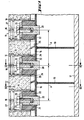
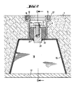
- Connection elements 6 are to be concreted into a filter floor 1 of a filter bed to be produced in the in-situ concrete, which are to be lined up at fixed intervals one behind the other in the longitudinal direction of a pure water collecting duct also to be concreted; only the ceiling formwork 17 is indicated by the channel.
- the individual connecting elements 6 are fastened to one another at an equal spacing A on a formwork body 15, for example made of steel or a reinforced, impact-resistant plastic; the formwork body 15 has a trapezoidal cross-section which widens downwards, which makes it easier to detach it after the concrete floor 1 has solidified.
- transverse stiffening walls 19 are attached between the brackets for the connecting elements 6.
- the brackets for the individual connecting elements 6 have supporting bolts 20 fastened in the formwork body 15, for example by welding or gluing, into which a thread 21 is cut from above.
- Cylindrical or barrel-shaped expansion bodies 22 are pushed over the support bolts 20, the height of which in the unloaded state, not shown, exceeds the height of the support bolts 20.
- cam-like projections 25 are fastened in alignment on the profile of the formwork body 15 between the described holders for the connecting elements 6 in the axial direction of the collecting duct to be created - likewise, for example, by welding or gluing .
- Corresponding grooves 26 are recessed at the lower edge of the connecting elements 6 to match the profile of these projections 25.
- the grooves 26 snap into the cams 25 and thus fix the connecting elements 6 with respect to a rotation about their axis, so that the threaded bores 16 are fixed relative to the axis of the collecting channel, for example, for all the connecting elements 6 at an equal angle of 90 0th
- the formwork body 15 is first fixed on the ceiling circuit 17 for the collecting duct. Then the connecting elements 6 are lined up on the still relaxed expansion bodies 22, the grooves 26 and the cams 25 intermeshing.
- the filter base 1 is produced by inserting the reinforcement, introducing and vibrating the concrete. After the concrete has solidified, the ceiling formwork 17 has been removed and the screws 24 have been loosened, the formwork body 15 can be removed downwards; it can then be used in the manner described for concreting a further section of the filter base 1.
- the invention is of course not limited to the exemplary embodiment shown. If, for example - as described in the aforementioned CH application - pipe clamps are attached to the filter base 1, the projections 27 with the threaded bores 16 are omitted on the flanges 10. The connecting elements 6 are then rotationally symmetrical without having a preferred direction. In this case, the cams 25 and the grooves 26 - as well as the projections 27 - of the described embodiment can be omitted.
Landscapes
- Chemical & Material Sciences (AREA)
- Chemical Kinetics & Catalysis (AREA)
- Forms Removed On Construction Sites Or Auxiliary Members Thereof (AREA)
- Filtration Of Liquid (AREA)
- Moulds, Cores, Or Mandrels (AREA)
- Biological Treatment Of Waste Water (AREA)
Priority Applications (1)
| Application Number | Priority Date | Filing Date | Title |
|---|---|---|---|
| AT79102988T ATE1538T1 (de) | 1979-05-31 | 1979-08-16 | Vorrichtung zum voruebergehenden fixieren von verbindungselementen fuer drainagerohre waehrend des einbetonierens in den boden eines filterfeldes. |
Applications Claiming Priority (2)
| Application Number | Priority Date | Filing Date | Title |
|---|---|---|---|
| CH508479A CH636399A5 (de) | 1979-05-31 | 1979-05-31 | Vorrichtung zum voruebergehenden fixieren von verbindungselementen fuer drainagerohre waehrend des einbetonierens in den boden eines filterfeldes. |
| CH5084/79 | 1979-05-31 |
Publications (2)
| Publication Number | Publication Date |
|---|---|
| EP0019655A1 true EP0019655A1 (fr) | 1980-12-10 |
| EP0019655B1 EP0019655B1 (fr) | 1982-09-15 |
Family
ID=4287670
Family Applications (1)
| Application Number | Title | Priority Date | Filing Date |
|---|---|---|---|
| EP79102988A Expired EP0019655B1 (fr) | 1979-05-31 | 1979-08-16 | Dispositif pour la fixation temporaire d'éléments de raccord de tuyaux de drainage dans le béton lors de la coulée de la plaque de fond d'un lit filtrant |
Country Status (4)
| Country | Link |
|---|---|
| EP (1) | EP0019655B1 (fr) |
| AT (1) | ATE1538T1 (fr) |
| CH (1) | CH636399A5 (fr) |
| DE (1) | DE2963678D1 (fr) |
Cited By (6)
| Publication number | Priority date | Publication date | Assignee | Title |
|---|---|---|---|---|
| EP0094487A1 (fr) * | 1982-03-30 | 1983-11-23 | MERCK PATENT GmbH | Hydroterphényles, leur préparation et leur utilisation dans des diélectriques à cristaux liquides |
| EP0104263A2 (fr) * | 1982-09-02 | 1984-04-04 | GebràDer Sulzer Aktiengesellschaft | Dispositif pour la fixation de tuyaux de drainage |
| FR2641588A1 (fr) * | 1989-01-09 | 1990-07-13 | Degremont | Dispositif pour la mise en place et la fixation, sur le plancher d'un filtre, d'organes assurant le transit de fluides a travers le plancher |
| EP0698407A1 (fr) * | 1994-08-26 | 1996-02-28 | Sulzer Chemtech AG | Réacteur pour le traitement des eaux usées pourvu d'une plaque distributrice avec des buses |
| WO2021024107A1 (fr) * | 2019-08-02 | 2021-02-11 | Tyco Fire Products Lp | Boîtier d'extincteur pour système de tuyau d'extincteur intégré |
| US10937285B2 (en) | 2018-06-01 | 2021-03-02 | Johnson Controls Fire Protection LP | Systems and methods of alarm controls and directed audio evacuation |
Families Citing this family (1)
| Publication number | Priority date | Publication date | Assignee | Title |
|---|---|---|---|---|
| AT391044B (de) * | 1987-09-09 | 1990-08-10 | Doepfl Rudolf Gmbh | Einrichtung zur pressung von in einem rahmen befindlichen packstuecken zur herstellung von kabeldurchfuehrungen |
Citations (4)
| Publication number | Priority date | Publication date | Assignee | Title |
|---|---|---|---|---|
| FR1013722A (fr) * | 1950-01-13 | 1952-08-04 | Trailigaz | Perfectionnements à la réalisation des filtres à sable |
| GB888202A (en) * | 1959-08-20 | 1962-01-31 | Alexander Feldmann | Improvements relating to means and methods of forming anchoring cavities in cast materials and to anchoring bolts for use therein |
| FR1405568A (fr) * | 1963-08-15 | 1965-07-09 | Sulzer Ag | Procédé de fabrication de fonds de filtre en béton, et fonds en résultant |
| US4159099A (en) * | 1977-05-09 | 1979-06-26 | Maguire James V | Sleeve assembly for forming openings in molded structures |
-
1979
- 1979-05-31 CH CH508479A patent/CH636399A5/de not_active IP Right Cessation
- 1979-08-16 DE DE7979102988T patent/DE2963678D1/de not_active Expired
- 1979-08-16 AT AT79102988T patent/ATE1538T1/de not_active IP Right Cessation
- 1979-08-16 EP EP79102988A patent/EP0019655B1/fr not_active Expired
Patent Citations (4)
| Publication number | Priority date | Publication date | Assignee | Title |
|---|---|---|---|---|
| FR1013722A (fr) * | 1950-01-13 | 1952-08-04 | Trailigaz | Perfectionnements à la réalisation des filtres à sable |
| GB888202A (en) * | 1959-08-20 | 1962-01-31 | Alexander Feldmann | Improvements relating to means and methods of forming anchoring cavities in cast materials and to anchoring bolts for use therein |
| FR1405568A (fr) * | 1963-08-15 | 1965-07-09 | Sulzer Ag | Procédé de fabrication de fonds de filtre en béton, et fonds en résultant |
| US4159099A (en) * | 1977-05-09 | 1979-06-26 | Maguire James V | Sleeve assembly for forming openings in molded structures |
Cited By (9)
| Publication number | Priority date | Publication date | Assignee | Title |
|---|---|---|---|---|
| EP0094487A1 (fr) * | 1982-03-30 | 1983-11-23 | MERCK PATENT GmbH | Hydroterphényles, leur préparation et leur utilisation dans des diélectriques à cristaux liquides |
| EP0104263A2 (fr) * | 1982-09-02 | 1984-04-04 | GebràDer Sulzer Aktiengesellschaft | Dispositif pour la fixation de tuyaux de drainage |
| EP0104263A3 (en) * | 1982-09-02 | 1986-06-11 | Gebruder Sulzer Aktiengesellschaft | Device for the fixation of drain pipes |
| FR2641588A1 (fr) * | 1989-01-09 | 1990-07-13 | Degremont | Dispositif pour la mise en place et la fixation, sur le plancher d'un filtre, d'organes assurant le transit de fluides a travers le plancher |
| EP0378024A1 (fr) * | 1989-01-09 | 1990-07-18 | Degremont S.A. | Dispositif pour la mise en place et la fixation, sur le plancher d'un filtre, d'organes assurant le transit de fluides à travers le plancher |
| US5087361A (en) * | 1989-01-09 | 1992-02-11 | Degremont | Filter floor nozzle housing and support arrangement |
| EP0698407A1 (fr) * | 1994-08-26 | 1996-02-28 | Sulzer Chemtech AG | Réacteur pour le traitement des eaux usées pourvu d'une plaque distributrice avec des buses |
| US10937285B2 (en) | 2018-06-01 | 2021-03-02 | Johnson Controls Fire Protection LP | Systems and methods of alarm controls and directed audio evacuation |
| WO2021024107A1 (fr) * | 2019-08-02 | 2021-02-11 | Tyco Fire Products Lp | Boîtier d'extincteur pour système de tuyau d'extincteur intégré |
Also Published As
| Publication number | Publication date |
|---|---|
| EP0019655B1 (fr) | 1982-09-15 |
| ATE1538T1 (de) | 1982-09-15 |
| CH636399A5 (de) | 1983-05-31 |
| DE2963678D1 (en) | 1982-11-04 |
Similar Documents
| Publication | Publication Date | Title |
|---|---|---|
| EP0119652A2 (fr) | Elément de liaison et de répartition de pression pour éléments en béton | |
| EP1757742A2 (fr) | Chambre d'infiltration avec canal de contrôle | |
| DE1958112C3 (fr) | ||
| DE3224986C2 (de) | Vorrichtung zur Befestigung von Montageteilen an einer Betonwand | |
| WO1988002049A1 (fr) | Dispositif pour la fixation de pieces de montage en forme de tube | |
| EP0019655B1 (fr) | Dispositif pour la fixation temporaire d'éléments de raccord de tuyaux de drainage dans le béton lors de la coulée de la plaque de fond d'un lit filtrant | |
| DE19607254C2 (de) | Hohlkörper für die Betonbauinstallation | |
| DE2422658B1 (de) | Wassereinlauf zur Entwässerung von Flachdächern, Baikonen, Terrassen od. dgl | |
| AT411079B (de) | Verfahren zur errichtung eines bauwerks mit einer umfangsgeschlossenen betonwand | |
| DE2823417C3 (de) | Schachtauskleidung zur Verwendung beim Aufwärtsbohren eines Schachtes und Schachtring für eine derartige Schachtauskleidung | |
| DE2800868A1 (de) | Befestigungsanordnung fuer foerderband-reinigungsvorrichtungen | |
| WO1998036885A1 (fr) | Systeme de coffrage pour la fabrication d'elements en beton | |
| DE3882532T2 (de) | Konstruktionsmethode für betonpfeiler für eine plattform oder ähnliche konstruktionen. | |
| DE3044232A1 (de) | Silobehaelter | |
| EP0908567B1 (fr) | Tirant d'ancrage pour cadre | |
| AT380079B (de) | Kraftwerkebausatz | |
| DE10305469A1 (de) | Brückenablauf | |
| DE102009049178A1 (de) | Schalung | |
| DE2703379C2 (de) | Belebtschlammanlage zur Abwasserreinigung | |
| CH639720A5 (en) | Panel ceiling | |
| EP0104263B1 (fr) | Dispositif pour la fixation de tuyaux de drainage | |
| EP0019658B1 (fr) | Installation de filtration pour le traitement de l'eau | |
| EP1435416A1 (fr) | Caniveau d'écoulement et méthode de production d'un tel caniveau d'écoulement | |
| DE2703583A1 (de) | Entwaesserungsrinne fuer begeh- und/oder befahrbare flaechen | |
| DE9015291U1 (de) | Flüssigkeitsabscheider |
Legal Events
| Date | Code | Title | Description |
|---|---|---|---|
| PUAI | Public reference made under article 153(3) epc to a published international application that has entered the european phase |
Free format text: ORIGINAL CODE: 0009012 |
|
| 17P | Request for examination filed | ||
| AK | Designated contracting states |
Designated state(s): AT DE FR GB IT NL |
|
| ITF | It: translation for a ep patent filed | ||
| GRAA | (expected) grant |
Free format text: ORIGINAL CODE: 0009210 |
|
| AK | Designated contracting states |
Designated state(s): AT DE FR GB IT NL |
|
| REF | Corresponds to: |
Ref document number: 1538 Country of ref document: AT Date of ref document: 19820915 Kind code of ref document: T |
|
| REF | Corresponds to: |
Ref document number: 2963678 Country of ref document: DE Date of ref document: 19821104 |
|
| PGFP | Annual fee paid to national office [announced via postgrant information from national office to epo] |
Ref country code: FR Payment date: 19840621 Year of fee payment: 6 |
|
| PGFP | Annual fee paid to national office [announced via postgrant information from national office to epo] |
Ref country code: DE Payment date: 19840824 Year of fee payment: 6 |
|
| PGFP | Annual fee paid to national office [announced via postgrant information from national office to epo] |
Ref country code: AT Payment date: 19850819 Year of fee payment: 7 |
|
| PGFP | Annual fee paid to national office [announced via postgrant information from national office to epo] |
Ref country code: NL Payment date: 19850831 Year of fee payment: 7 |
|
| PG25 | Lapsed in a contracting state [announced via postgrant information from national office to epo] |
Ref country code: AT Effective date: 19860816 |
|
| PG25 | Lapsed in a contracting state [announced via postgrant information from national office to epo] |
Ref country code: NL Effective date: 19870301 |
|
| NLV4 | Nl: lapsed or anulled due to non-payment of the annual fee | ||
| GBPC | Gb: european patent ceased through non-payment of renewal fee | ||
| PG25 | Lapsed in a contracting state [announced via postgrant information from national office to epo] |
Ref country code: FR Free format text: LAPSE BECAUSE OF NON-PAYMENT OF DUE FEES Effective date: 19870430 |
|
| PG25 | Lapsed in a contracting state [announced via postgrant information from national office to epo] |
Ref country code: DE Effective date: 19870501 |
|
| REG | Reference to a national code |
Ref country code: FR Ref legal event code: ST |
|
| PG25 | Lapsed in a contracting state [announced via postgrant information from national office to epo] |
Ref country code: GB Effective date: 19881118 |
|
| PLBE | No opposition filed within time limit |
Free format text: ORIGINAL CODE: 0009261 |
|
| STAA | Information on the status of an ep patent application or granted ep patent |
Free format text: STATUS: NO OPPOSITION FILED WITHIN TIME LIMIT |