EP0018291B1 - Machine d'impression avec possibilité de changement de format - Google Patents
Machine d'impression avec possibilité de changement de format Download PDFInfo
- Publication number
- EP0018291B1 EP0018291B1 EP80400528A EP80400528A EP0018291B1 EP 0018291 B1 EP0018291 B1 EP 0018291B1 EP 80400528 A EP80400528 A EP 80400528A EP 80400528 A EP80400528 A EP 80400528A EP 0018291 B1 EP0018291 B1 EP 0018291B1
- Authority
- EP
- European Patent Office
- Prior art keywords
- printing
- speed
- web
- contact
- sheet
- Prior art date
- Legal status (The legal status is an assumption and is not a legal conclusion. Google has not performed a legal analysis and makes no representation as to the accuracy of the status listed.)
- Expired
Links
Images

Classifications
-
- B—PERFORMING OPERATIONS; TRANSPORTING
- B41—PRINTING; LINING MACHINES; TYPEWRITERS; STAMPS
- B41F—PRINTING MACHINES OR PRESSES
- B41F13/00—Common details of rotary presses or machines
- B41F13/02—Conveying or guiding webs through presses or machines
- B41F13/04—Conveying or guiding webs through presses or machines intermittently
Definitions
- the invention relates to a printing machine with a rotary printing cylinder for printing a web with the possibility of changing the format, that is to say the length of the web which runs at each cycle.
- a printing machine which comprises downstream of the printing cylinder an endless tractor with pins to drive the web forwards at a call speed at most equal to printing speed and, upstream of the cylinder printing, a device for returning the web backwards to absorb during each printing cycle the excess length provided by the printing speed drive compared to the calling speed drive.
- the publication FR-A-2 025 390 describes such a printing machine in which said tractor with pins is rotated by a predetermined angle during each period of driving the web forwards and is fixed during each period in which the web is released by the printing torque.
- the present invention aims to provide a printing machine for changing the format while avoiding inertia due to the fact that the tractor must alternately be driven and stopped or due to the fact that there is a mechanical connection between the tractor and the device. reminder.
- the tractor with spikes is freely rotating, that the machine comprises a rotor permanently driven at the call speed and which drives the tractor with spikes by contact with a stop said rotor with a stop of the tractor, and that the machine comprises another rotary member downstream of the printing cylinder to drive the web at the printing speed in synchronism with the printing contact.
- the invention applies to all printing processes (letterpress, dry offset, wet offset, heliographic) and it allows the use of sheet paper of a wide variety of grammages and quality.
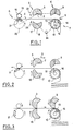
- Figures 1 to 6 show different phases of a printing cycle.
- the device shown in Figures 1 to 6 comprises a printing machine 1 shown schematically by a printing cylinder 2 having a printing surface 3 which is assumed for example to cover three quarters of the surface of the cylinder and by a back pressure cylinder 17.
- a printing machine 1 shown schematically by a printing cylinder 2 having a printing surface 3 which is assumed for example to cover three quarters of the surface of the cylinder and by a back pressure cylinder 17.
- the other accessories of the printing device have not been shown.
- the printing cylinder acts on the web 4 when there is contact between this web and the printing surface, due to the pinching of the web between the printing surface 3 and a counterpart surface 18 of the cylinder. 17.
- the device shown comprises, downstream of the printing machine, in the direction of travel of the web shown by arrow 5, a device 6 for pulling the web in the direction of arrow 5 at a speed equal to the speed d printing and a device 7 for pulling the sheet in the direction of arrow 5 at a calling speed.
- the device also comprises, upstream of the machine 1, a return device 8 for returning the sheet in the opposite direction to the normal direction of travel 5.
- the device 6 is designed to drive the web in synchronism with the printing, that is to say that the start and the end of this training coincide with the start and the end of the printing and that the driving speed coincides with the tangential speed of the printing cylinder, speed which has been called "printing speed”.
- the device 6 is constituted for example by a cam whose surface has the same shape and the same angular extent as the printing surface, this cam being driven in rotation at the same speed as the printing cylinder, the angular positions of this cam and the printing surface being identical to obtain the desired coincidences of the contacts with the web.
- this cam is shown diagrammatically by a sector 9 of a circle.
- the device 7 is designed to drive the web at a chosen speed, called the "calling speed" which is at most equal to the printing speed.
- This device comprises, in a preferred embodiment, a crown 10 provided with pins capable of meshing in staggered perforations along the ply (for example so-called “Caroll” perforations) this crown being mounted idle coaxially with a rotor 12 which is continuously rotating at the call speed and which is provided with a stop 13 capable of coming into contact with a stop 14 of the crown in order to drive the latter at the call speed.
- cam 9 and the pin ring 10 are located opposite as shown, but in alternative embodiments, they are offset, the cam being downstream of the ring.
- the device 8 is designed to permanently exert a certain tension on the web and to recall the web 4 backwards after each printing, when this is necessary, that is to say if the printing speed is greater than the call speed.
- This device 8 comprises a rotor 16 with peripheral balls 19 and a rotor 20 with cam 21 cooperating.
- the ply is normally tensioned by friction between the balls 19 and the surface of the rotor 20 but when the cam 21 which is projecting passes in contact with the ply, the friction becomes sufficient to exert a backward return on the sheet.
- the cam 21 is synchronized with the printing surface so that the start of the return contact of the web by this cam coincides with the end of the print contact of the printing surface 2 with the web.
- FIG. 2 shows the start of the cycle.
- the tablecloth is free except that it is engaged with the pin ring 10 whose stop 14 is driven by the stop 13 of the rotor 12 at the call speed: the tablecloth therefore advances at this speed in the direction of arrow 5, the return by the cam 21 having ended.
- the next phase is a printing phase during which the printing surface is in printing contact with the web and during which the web is pulled forward by the cam 9.
- This pulling takes place at a higher speed. at the call speed, it is no longer the spike crown which can drive the ply, but on the contrary it is the ply which imposes its speed which is then the printing speed on the spike crown whose stop 14 takes the lead with respect to the stop 13 of the rotor 12 which rotates at the call speed lower than the printing speed:
- FIG. 4 diagrams this phase and it can be seen there that there is an angular difference between the stops 13 and 14.
- the rotor 12 can again drive the web at the call speed through the pivot crown, until the printing surface is in contact with the web while the second cycle has already started.
- Figure 1 the diagram of the control of the various rotary members from a common power take-off.
- a gear (not shown) between the cylinders 2 and 17 so that they rotate in opposite directions.
- the printing cylinder is a driving cylinder which rotates in the direction of arrow 22
- drive connections are made between this cylinder and the rotors 9 and 20 so that the cams 9 and 21 rotate as the engine cylinder.
- the counterpressure cylinder 17 rotates in the opposite direction 23 and a drive link is established comprising a pinion 21 between the cylinder 17 and the rotor 12 so that the rotor rotates in the same direction as the cylinder 17 but with a speed which depends on the choice of pinion.
- the drive links are shown diagrammatically by broken lines.
- the variation of the paper format is obtained by changing a control gear controlling the call of the paper, in this case the tractor with pins 10.
- FIG. 6 represents a case of reduction of the format.
- the contact time in the cycle will be reduced to approach the print format (this can also be different from the format of the print),
- Example: the height of the print can be equal or lower at the height of the format 1, 2, 3,4, 5, 6, ... inches for a 10 inch paper format.
- the adjustment of the counterpart with respect to the upper part limits the loop of the paper downstream and thereby reduces the length of paper to be caught up during free time. Furthermore; it increases the free time per cycle, which compensates for the growth in minus - plus, plus - minus differences in speed, when the format decreases while leaving a longer catch-up time.
- the opening in the cylinders 2 and 17 is calculated so that their respective adjustment can pass from the maximum contact surface to a minimum contact surface of half the maximum contact.
- the variation in format corresponds to the choice of the gearbox module which controls the advance of the paper. If a tooth of the format pinion corresponds to 1/6 of an inch, the variation of format may take place every 1/6 of an inch.
- the adjustments make it possible to reduce or increase the contact surface of the web and therefore make it possible to maintain a practically constant backward flow of the paper web.
Description
- L'invention concerne une machine d'impression à cylindre d'impression rotatif pour imprimer une nappe avec possibilité de changer le format, c'est-à-dire la longueur de la nappe qui défile à chaque cycle.
- On connaît une machine d'impression qui comporte en aval du cylindre d'impression un tracteur sans fin à picots pour entraîner la nappe vers l'avant à une vitesse d'appel au plus égale à vitesse d'impression et, en amont du cylindre d'impression, un dispositif de rappel de la nappe vers l'arrière pour résorber pendant chaque cycle d'impression l'excès de longueur procuré par l'entraînement à vitesse d'impression par rapport à l'entraînement à vitesse d'appel.
- La publication FR-A-2 025 390 décrit une telle machine d'impression dans laquelle ledit tracteur à picots est entraîné en rotation d'un angle prédéterminé pendant chaque période d'entraînement de la nappe vers l'avant et est fixe pendant chaque période dans laquelle la nappe est libérée par le couple d'impression.
- On connaît également une machine d'impression (US-A-2 039 236) dans laquelle le tracteur et le dispositif de rappel sont des organes rotatifs reliés par une chaîne de transmission.
- La présente invention vise à fournir une machine d'impression permettant de changer le format tout en évitant les inerties dues au fait que le tracteur doit alternativement être entraîné et arrêté ou dues au fait qu'il existe une liaison mécanique entre le tracteur et le dispositif de rappel.
- On y parvient, selon l'invention, par le fait que le tracteur à picots est à rotation libre, que la machine comporte un rotor entraîné en permanence à la vitesse d'appel et qui entraîne le tracteur à picots par contact d'une butée dudit rotor avec une butée du tracteur, et que la machine comporte un autre organe rotatif en aval du cylindre d'impression pour entraîner la nappe à la vitesse d'impression en synchronisme avec le contact d'impression.
- On évite ainsi, selon l'invention, des mouvements successifs de marche et d'arrêt.
- L'invention s'applique à tous les procédés d'impression (typographique, offset sec, offset humide, héliographique) et elle permet l'utilisation du papier en nappe d'une grande diversité de grammages et de qualité.
- Les figures 1 à 6 représentent différentes phases d'un cycle d'impression.
- Le dispositif représenté sur les figures 1 à 6 comprend une machine d'impression 1 schématisée par un cylindre d'impression 2 comportant une surface d'impression 3 dont on suppose pour l'exemple qu'elle couvre les trois quarts de la surface du cylindre et par un cylindre de contre-pression 17. Pour la clarté du dessin, on n'a pas représenté les autres accessoires du dispositif d'impression.
- Le cylindre d'impression agit sur la nappe 4 lorsqu'il y a contact entre cette nappe et la surface d'impression, du fait du pincement de la nappe entre la surface d'impression 3 et une surface de contre-partie 18 du cylindre 17.
- Le dispositif représenté comprend, en aval de la machine d'impression, dans le sens du défilement de la nappe représenté par la flèche 5, un dispositif 6 pour tirer la nappe dans le sens de la flèche 5 à une vitesse égale à la vitesse d'impression et un dispositif 7 pour tirer la nappe dans le sens de la flèche 5 à une vitesse d'appel.
- Le dispositif comprend également, en amont de la machine 1, un dispositif de rappel 8 pour rappeler la nappe dans le sens inverse du sens normal du défilement 5.
- Le dispositif 6 est conçu pour entraîner la nappe en synchronisme avec l'impression, c'est-à-dire que le début et la fin de cet entraînement coïncident avec le début et la fin de l'impression et que la vitesse d'entraînement coïncide avec la vitesse tangentielle du cylindre d'impression, vitesse que l'on a appelé »vitesse d'impression«.
- Le dispositif 6 est constitué par exemple par une came dont la surface a la même forme et la même étendue angulaire que la surface d'impression, cette came étant entraînée en rotation à la même vitesse que le cylindre d'impression, les positions angulaires de cette came et de la surface d'impression étant identiques pour obtenir les coïncidences désirées des contacts avec la nappe. Sur les figures, cette came est schématisée par un secteur 9 d'un cercle.
- Le dispositif 7 est conçu pour entraîner la nappe à une vitesse choisie, dite »vitesse d'appel« qui est au plus égale à la vitesse d'impression. Ce dispositif comprend, dans une réalisation préférée, une couronne 10 pourvue de picots aptes à engrèner dans des perforations échelonnées le long de la nappe (par exemple perforations dites »Caroll«) cette couronne étant montée folle coaxialement à un rotor 12 qui tourne en permanence à la vitesse d'appel et qui est muni d'une butée 13 apte à venir en contact avec une butée 14 de la couronne afin d'entraîner cette dernière à la vitesse d'appel.
- De préférence la came 9 et la couronne à picots 10 sont situées en vis-à-vis comme représentées, mais dans des variantes de réalisation, elles sont décalées, la came étant en aval de la couronne.
- Le dispositif 8 est conçu pour exercer en permanence une certaine tension sur la nappe et pour rappeler vers l'arrière la nappe 4 après chaque impression, lorsque cela est nécessaire, c'est-à-dire si la vitesse d'impression est supérieure à la vitesse d'appel. Ce dispositif 8 comprend un rotor 16 à billes périphériques 19 et un rotor 20 à came 21 coopérant. La nappe est normalement tendue par friction entre les billes 19 et la surface du rotor 20 mais lorsque la came 21 qui est en saillie passe au contact de la nappe, la friction devient suffisante pour exercer sur la nappe un rappel vers l'arrière. La came 21 est synchronisée avec la surface d'impression pour que le début du contact de rappel de la nappe par cette came coïncide avec la fin du contact d'impression de la surface d'impression 2 avec la nappe.
- On décrira maintenant un cycle d'impression, en supposant que le cycle commence un peu avant le début d'une impression et se termine un peu après la fin d'une impression.
- La figure 2 représente le début du cycle. La nappe est libre si ce n'est qu'elle est en prise avec la couronne à picots 10 dont la butée 14 est entraînée par la butée 13 du rotor 12 à la vitesse d'appel: la nappe avance donc à cette vitesse dans le sens de la flèche 5, le rappel par la came 21 ayant pris fin.
- On suppose maintenant que la surface d'impression vient en contact d'impression avec la nappe (figure 3). A ce moment, la came d'entraînement du dispositif 6 vient également en contact d'entraînement avec la nappe.
- La phase suivante est une phase d'impression pendant laquelle la surface d'impression est en contact d'impression avec la nappe et pendant laquelle la nappe est tirée vers l'avant pas la came 9. Cette traction se faisant .à une vitesse supérieure à la vitesse d'appel, ce n'est plus la couronne à picots qui peut entraîner la nappe mais c'est au contraire la nappe qui impose sa vitesse qui est alors la vitesse d'impression à la couronne à picots dont la butée 14 prend de l'avance par rapport à la butée 13 du rotor 12 qui tourne à la vitesse d'appel inférieure à la vitesse d'impression: la figure 4 schématise cette phase et l'on y voit qu'il existe un écart angulaire entre les butées 13 et 14.
- On suppose maintenant que l'on se trouve à la fin de la phase d'impression (figure 5) alors que vont cesser d'une part le contact d'impression de la surrace 2 et de la nappe 4 et d'autre part, le contact d'entraînement de la came 9 et de la nappe 4, la nappe se trouvant ainsi libérée, tandis que simultanément va commencer le contact de rappel de la came 21 et de la nappe. Sous l'effet du rappel de la came 21, la nappe revient en arrière et entraîne dans son mouvement la couronne à picots dont la butée revient également en arrière en se rapprochant de la butée 13 du rotor qui a continué de tourner dans le sens de la vitesse d'appel (figure 1).
- Lorsque ce contact est réalisé, le rotor 12 peut à nouveau entraîner la nappe à la vitesse d'appel par l'intermédiaire de la couronne à pivots, jusqu'à ce que la surface d'impression se retrouve en contact avec la nappe alors que le deuxième cycle a déjà commencé.
- On a représenté sur la figure 1, le schéma de la commande des différents organes rotatifs à partir d'une prise de mouvement commune. Il existe un engrenage (non représenté) entre les cylindres 2 et 17 en sorte qu'ils tournent en sens inverse. Si l'on suppose que le cylindre d'impression est un cylindre menant qui tourne dans le sens de la flèche 22, on réalise des liaisons d'entraînement entre ce cylindre et les rotors 9 et 20 pour que les cames 9 et 21 tournent comme le cylindre moteur. Le cylindre de contrepression 17 tourne en sens inverse 23 et l'on établit une liaison d'entraînement comprenant un pignon 21 entre le cylindre 17 et le rotor 12 pour que le rotor tourne dans le même sens que le cylindre 17 mais avec une vitesse qui dépend du choix du pignon. Sur la figure, les liaisons d'entraînement sont schématisés par des lignes de traits interrompus.
-
- - Le tracteur à picots 10 entraîne le papier à vitesse continue constante. Le format considéré pour un cycle sera par exempte de 12 pouces.
- - La came 9 et le cylindre d'impression 2 tournent à vitesse continue et constante.-Un tour de cylindre correspond à un cycle. Les cylindres 2 et 17 ont un évidement de 6 pouces 1/2. Lorsque ces cylindres sont en contact maximum, cette surface est équivalente à 12 pouces 1/2, ce qui donne une vitesse totale de 19 pouces par cycle.
- La variation du format de papier s'obtient en changeant un pignon de commande commandant l'appel du papier, en l'occurence le tracteur à picots 10.
- Exemple: le changement de pignon fera débiter 10 pouces par cycle au lieu de 12 comme expliqué initialement.
- Le développement des cylindes 9 et 2 restera à 19 pouces par cycle. L'écart de vitesse se trouve agrandi de 2 pouces.
- Pour éviter de débiter trop de papier pendant la phase d'impression, on procède au réglage angulaire des contre-parties 17 et 9. La figure 6 représente un cas de réduction du format.
- Le temps de contact dans le cycle se trouvera diminué pour s'approcher du format d'impression (celui-ci peut d'ailleurs être différent du format de l'imprimé), Exemple: la hauteur de l'imprimé peut être égale ou inférieure à la hauteur du format 1, 2, 3,4, 5, 6, ... pouces pour un format de papier de 10 pouces.
- Le réglage de la contre-partie par rapport à la partie supérieure limite la boucle du papier en aval et de ce fait réduit la longueur de papier à rattraper pendant le temps libre. De plus; il augmente le temps libre par cycle, ce qui compense la croissance des écarts de bitesse moins - plus, plus - moins, lorsque le format diminue en laissant un temps de rattrapage plus long.
- Dans cet exemple non limitatif, l'ouverture dans les cylindes 2 et 17 est calculée de telle sorte que leur réglage respectif puisse passer de la surface de contact maximum à une surface de contact minimale de la moitié du contact maximale.
- La variation de format correspond au choix du module de la pignonnerie qui commande l'avance du papier. Si une dent du pignon de format correspond à 1/6 de pouce, la variation de format pourra s'opérer chaque 1/6 de pouce. Les réglages permettent de réduire ou d'augmenter la surface de contact de la nappe et, permettent donc de conserver un retour arrière pratiquement constant de la nappe de papier.
Claims (7)
Priority Applications (1)
| Application Number | Priority Date | Filing Date | Title |
|---|---|---|---|
| AT80400528T ATE3763T1 (de) | 1979-04-18 | 1980-04-18 | Auf unterschiedliche formate einstellbare druckmaschine. |
Applications Claiming Priority (2)
| Application Number | Priority Date | Filing Date | Title |
|---|---|---|---|
| FR7909719 | 1979-04-18 | ||
| FR7909719A FR2454369A1 (fr) | 1979-04-18 | 1979-04-18 | Procede et dispositif pour commander le defilement d'une nappe dans une machine d'impression |
Publications (2)
| Publication Number | Publication Date |
|---|---|
| EP0018291A1 EP0018291A1 (fr) | 1980-10-29 |
| EP0018291B1 true EP0018291B1 (fr) | 1983-06-15 |
Family
ID=9224414
Family Applications (1)
| Application Number | Title | Priority Date | Filing Date |
|---|---|---|---|
| EP80400528A Expired EP0018291B1 (fr) | 1979-04-18 | 1980-04-18 | Machine d'impression avec possibilité de changement de format |
Country Status (7)
| Country | Link |
|---|---|
| US (1) | US4372206A (fr) |
| EP (1) | EP0018291B1 (fr) |
| JP (1) | JPS56500561A (fr) |
| AT (1) | ATE3763T1 (fr) |
| DE (1) | DE3063745D1 (fr) |
| FR (1) | FR2454369A1 (fr) |
| WO (1) | WO1980002258A1 (fr) |
Cited By (1)
| Publication number | Priority date | Publication date | Assignee | Title |
|---|---|---|---|---|
| DE10311219A1 (de) * | 2003-03-14 | 2004-09-30 | Werner Kammann Maschinenfabrik Gmbh | Verfahren und Vorrichtung zum Bedrucken einer Bahn |
Families Citing this family (10)
| Publication number | Priority date | Publication date | Assignee | Title |
|---|---|---|---|---|
| FR2561175B1 (fr) * | 1984-03-15 | 1986-10-24 | Codimag | Procede et dispositif d'impression a grand rendement |
| US4839814A (en) * | 1985-01-29 | 1989-06-13 | Moore Business Forms, Inc. | Size independent modular web processing line and modules |
| US4716802A (en) * | 1986-01-20 | 1988-01-05 | Corfine Inc. | Scrap reduction system for rotary die cutter |
| US4751879A (en) * | 1987-03-18 | 1988-06-21 | Van Pelt Equipment Corporation | Method and apparatus for intermittently processing successive definite lengths of a continuous flexible web |
| US5115737A (en) * | 1990-04-16 | 1992-05-26 | Philip Morris Incorporated | Hot rotary stamper apparatus and methods for metal leaf stamping |
| ES2049143B1 (es) * | 1991-11-04 | 1997-11-16 | Cremades Martinez Francisco | Sistema y maquina de impresion multiple en continuo. |
| CA2117665C (fr) * | 1993-09-17 | 2006-01-10 | Joachim Alfred Heinz Lapp | Unite d'impression pour machine a imprimer utilisant du papier continu |
| US5417360A (en) * | 1993-09-28 | 1995-05-23 | Moore Business Forms, Inc. | Feeding of offset, collated forms |
| US7926688B2 (en) * | 2005-08-23 | 2011-04-19 | Durst Phototechnik Ag | Tension-controlled web processing machine and method |
| CN105015156B (zh) * | 2015-07-22 | 2018-06-26 | 河北海贺胜利印刷机械集团有限公司 | 间歇式正向跳步印刷机及其控制方法和跳步牵引装置 |
Family Cites Families (6)
| Publication number | Priority date | Publication date | Assignee | Title |
|---|---|---|---|---|
| US2039236A (en) * | 1935-01-02 | 1936-04-28 | Meisel Press Mfg Company | All size rotary web press |
| US2845021A (en) * | 1955-03-28 | 1958-07-29 | Bemis Bro Bag Co | Web feed means for rotary printing press |
| US3420158A (en) * | 1967-01-31 | 1969-01-07 | Signode Corp | Strap feed and tensioning mechanism |
| US3548747A (en) * | 1968-12-05 | 1970-12-22 | American Bank Note Co | Web-fed rotary printing press |
| US3762322A (en) * | 1972-05-04 | 1973-10-02 | G Vines | Printing machine |
| FR2342849A2 (fr) * | 1976-03-05 | 1977-09-30 | Seailles Tison Atel Const Meca | Dispositif a differentiel pour commander le defilement d'une nappe a imprimer dans une machine d'impression rotative |
-
1979
- 1979-04-18 FR FR7909719A patent/FR2454369A1/fr not_active Withdrawn
-
1980
- 1980-04-18 EP EP80400528A patent/EP0018291B1/fr not_active Expired
- 1980-04-18 DE DE8080400528T patent/DE3063745D1/de not_active Expired
- 1980-04-18 WO PCT/FR1980/000060 patent/WO1980002258A1/fr unknown
- 1980-04-18 US US06/224,541 patent/US4372206A/en not_active Expired - Lifetime
- 1980-04-18 AT AT80400528T patent/ATE3763T1/de not_active IP Right Cessation
- 1980-04-18 JP JP50083080A patent/JPS56500561A/ja active Pending
Cited By (1)
| Publication number | Priority date | Publication date | Assignee | Title |
|---|---|---|---|---|
| DE10311219A1 (de) * | 2003-03-14 | 2004-09-30 | Werner Kammann Maschinenfabrik Gmbh | Verfahren und Vorrichtung zum Bedrucken einer Bahn |
Also Published As
| Publication number | Publication date |
|---|---|
| FR2454369A1 (fr) | 1980-11-14 |
| WO1980002258A1 (fr) | 1980-10-30 |
| ATE3763T1 (de) | 1983-06-15 |
| JPS56500561A (fr) | 1981-04-30 |
| EP0018291A1 (fr) | 1980-10-29 |
| US4372206A (en) | 1983-02-08 |
| DE3063745D1 (en) | 1983-07-21 |
Similar Documents
| Publication | Publication Date | Title |
|---|---|---|
| EP0018291B1 (fr) | Machine d'impression avec possibilité de changement de format | |
| EP0192904B1 (fr) | Presse à fourrage pour la production de balles roulées avec mécanisme de liage | |
| FR2636108A1 (fr) | Dispositif pour regler la position angulaire relative de deux arbres relies selon une liaison motrice | |
| FR2680480A1 (fr) | Machine a couper et a plier une bande de papier imprime. | |
| FR2478023A1 (fr) | Machine pour conditionner completement une denree a l'aide d'un plateau | |
| EP0351290B1 (fr) | Machine de conditionnement en continu de produits en particulier alimentaires ou pharmaceutiques, dans des récipients en matière plastique | |
| FR2711576A1 (fr) | Dispositif de commande de l'accumulation ou non accumulation d'un cylindre coupeur-accumulateur d'une plieuse. | |
| FR2718723A1 (fr) | Dispositif de sortie de cahiers d'une roue à aubes. | |
| CH414449A (fr) | Appareil pour cercler des colis à l'aide de feuillard | |
| FR2693946A1 (fr) | Procédé et dispositif de mise en marche/arrêt du retournement des feuilles et d'ajustement du format dans le transport de feuilles à travers une machine d'impression. | |
| FR2621858A1 (fr) | Plieuse pour imprimes | |
| FR2643589A1 (fr) | Machine a couper et a plier une bande de papier imprime | |
| FR2899602A1 (fr) | Ratiere rotative, metier a tisser comprenant une telle ratiere et procede de commande d'une telle ratiere | |
| FR2635719A1 (fr) | Presse rotative typographique a feuilles pour belle page et retiration | |
| FR2685878A1 (fr) | Poupee faisant du patin a roulettes. | |
| EP0918580B1 (fr) | Dispositif pour deplacer une partie d'une machine et exercer un effort en fin de course | |
| FR2520204A1 (fr) | Machine de conditionnement de poissons pourvue d'un dispositif de commande des outils de conditionnement | |
| FR2781008A1 (fr) | Variateur de calage de distribution a grand debattement | |
| EP0384801B1 (fr) | Dispositif de coupe rotative pour bande d'ouate de cellulose ou autre matériau souple et utilisation d'un tel dispositif | |
| FR2544825A1 (fr) | Dispositif de commande selective du mouvement de rotation d'un arbre | |
| WO1988006553A1 (fr) | Dispositif de nouage d'un lien souple | |
| FR2796930A1 (fr) | Dispositif pour le reglage de phase de dispositifs de perforation en fonction du mode de pliage | |
| CH423601A (fr) | Dispositif pour l'empaquetage d'objets sous forme cylindrique ou prismatique | |
| FR2717545A1 (fr) | Procédé et dispositif pour une transmission de puissance du type à changement de vitesse continument variable, avec fonction d'embrayage. | |
| CH116187A (fr) | Machine-outil. |
Legal Events
| Date | Code | Title | Description |
|---|---|---|---|
| PUAI | Public reference made under article 153(3) epc to a published international application that has entered the european phase |
Free format text: ORIGINAL CODE: 0009012 |
|
| AK | Designated contracting states |
Designated state(s): AT BE CH DE GB IT LU NL SE |
|
| 17P | Request for examination filed |
Effective date: 19810326 |
|
| ITF | It: translation for a ep patent filed |
Owner name: SOCIETA' ITALIANA BREVETTI S.P.A. |
|
| GRAA | (expected) grant |
Free format text: ORIGINAL CODE: 0009210 |
|
| AK | Designated contracting states |
Designated state(s): AT BE CH DE GB IT LI LU NL SE |
|
| PG25 | Lapsed in a contracting state [announced via postgrant information from national office to epo] |
Ref country code: SE Effective date: 19830615 Ref country code: NL Effective date: 19830615 |
|
| REF | Corresponds to: |
Ref document number: 3763 Country of ref document: AT Date of ref document: 19830615 Kind code of ref document: T |
|
| PG25 | Lapsed in a contracting state [announced via postgrant information from national office to epo] |
Ref country code: AT Effective date: 19830701 |
|
| REF | Corresponds to: |
Ref document number: 3063745 Country of ref document: DE Date of ref document: 19830721 |
|
| NLV1 | Nl: lapsed or annulled due to failure to fulfill the requirements of art. 29p and 29m of the patents act | ||
| PGFP | Annual fee paid to national office [announced via postgrant information from national office to epo] |
Ref country code: LU Payment date: 19840328 Year of fee payment: 5 |
|
| PGFP | Annual fee paid to national office [announced via postgrant information from national office to epo] |
Ref country code: BE Payment date: 19840331 Year of fee payment: 5 |
|
| PGFP | Annual fee paid to national office [announced via postgrant information from national office to epo] |
Ref country code: DE Payment date: 19840427 Year of fee payment: 5 |
|
| PG25 | Lapsed in a contracting state [announced via postgrant information from national office to epo] |
Ref country code: LU Free format text: LAPSE BECAUSE OF NON-PAYMENT OF DUE FEES Effective date: 19840430 |
|
| PGFP | Annual fee paid to national office [announced via postgrant information from national office to epo] |
Ref country code: CH Payment date: 19840503 Year of fee payment: 5 |
|
| PLBE | No opposition filed within time limit |
Free format text: ORIGINAL CODE: 0009261 |
|
| STAA | Information on the status of an ep patent application or granted ep patent |
Free format text: STATUS: NO OPPOSITION FILED WITHIN TIME LIMIT |
|
| 26N | No opposition filed | ||
| PG25 | Lapsed in a contracting state [announced via postgrant information from national office to epo] |
Ref country code: LI Effective date: 19850430 Ref country code: CH Effective date: 19850430 Ref country code: BE Effective date: 19850430 |
|
| BERE | Be: lapsed |
Owner name: ETS. DESTOUCHE Effective date: 19850418 Owner name: CODIMAG Effective date: 19850418 |
|
| GBPC | Gb: european patent ceased through non-payment of renewal fee | ||
| REG | Reference to a national code |
Ref country code: CH Ref legal event code: PL |
|
| PG25 | Lapsed in a contracting state [announced via postgrant information from national office to epo] |
Ref country code: DE Effective date: 19860101 |
|
| PG25 | Lapsed in a contracting state [announced via postgrant information from national office to epo] |
Ref country code: GB Effective date: 19881118 |