EP0017085B1 - Verfahren und Vorrichtung zum elektrolytischen Abscheiden von Metallen, insbesondere Kupfer - Google Patents
Verfahren und Vorrichtung zum elektrolytischen Abscheiden von Metallen, insbesondere Kupfer Download PDFInfo
- Publication number
- EP0017085B1 EP0017085B1 EP80101438A EP80101438A EP0017085B1 EP 0017085 B1 EP0017085 B1 EP 0017085B1 EP 80101438 A EP80101438 A EP 80101438A EP 80101438 A EP80101438 A EP 80101438A EP 0017085 B1 EP0017085 B1 EP 0017085B1
- Authority
- EP
- European Patent Office
- Prior art keywords
- cathode
- fact
- acc
- fixing
- points
- Prior art date
- Legal status (The legal status is an assumption and is not a legal conclusion. Google has not performed a legal analysis and makes no representation as to the accuracy of the status listed.)
- Expired
Links
- 238000000034 method Methods 0.000 title claims abstract description 26
- 239000002184 metal Substances 0.000 title claims abstract description 11
- 229910052751 metal Inorganic materials 0.000 title claims abstract description 11
- 230000008569 process Effects 0.000 title claims description 16
- 150000002739 metals Chemical class 0.000 title abstract description 6
- 238000000151 deposition Methods 0.000 title description 13
- RYGMFSIKBFXOCR-UHFFFAOYSA-N Copper Chemical compound [Cu] RYGMFSIKBFXOCR-UHFFFAOYSA-N 0.000 title description 6
- 229910052802 copper Inorganic materials 0.000 title description 6
- 239000010949 copper Substances 0.000 title description 6
- 239000003792 electrolyte Substances 0.000 claims abstract description 15
- 238000000926 separation method Methods 0.000 claims abstract description 9
- 238000005868 electrolysis reaction Methods 0.000 claims description 11
- 230000008859 change Effects 0.000 claims description 7
- -1 polypropylene Polymers 0.000 claims description 7
- 239000004698 Polyethylene Substances 0.000 claims description 3
- 239000004743 Polypropylene Substances 0.000 claims description 3
- 229920000573 polyethylene Polymers 0.000 claims description 3
- 229920001155 polypropylene Polymers 0.000 claims description 3
- 229910052573 porcelain Inorganic materials 0.000 claims description 3
- 230000033764 rhythmic process Effects 0.000 claims description 3
- 229920001875 Ebonite Polymers 0.000 claims description 2
- 230000001105 regulatory effect Effects 0.000 abstract 1
- 230000008021 deposition Effects 0.000 description 12
- 238000004519 manufacturing process Methods 0.000 description 5
- 238000012544 monitoring process Methods 0.000 description 4
- 238000007670 refining Methods 0.000 description 4
- 230000015572 biosynthetic process Effects 0.000 description 3
- 239000000463 material Substances 0.000 description 3
- 239000004033 plastic Substances 0.000 description 3
- 229920003023 plastic Polymers 0.000 description 3
- PXHVJJICTQNCMI-UHFFFAOYSA-N Nickel Chemical compound [Ni] PXHVJJICTQNCMI-UHFFFAOYSA-N 0.000 description 2
- 230000008901 benefit Effects 0.000 description 2
- 210000005069 ears Anatomy 0.000 description 2
- 230000008030 elimination Effects 0.000 description 2
- 238000003379 elimination reaction Methods 0.000 description 2
- 238000002474 experimental method Methods 0.000 description 2
- 238000010438 heat treatment Methods 0.000 description 2
- 238000009413 insulation Methods 0.000 description 2
- 230000001681 protective effect Effects 0.000 description 2
- 230000009467 reduction Effects 0.000 description 2
- JXYWFNAQESKDNC-BTJKTKAUSA-N (z)-4-hydroxy-4-oxobut-2-enoate;2-[(4-methoxyphenyl)methyl-pyridin-2-ylamino]ethyl-dimethylazanium Chemical compound OC(=O)\C=C/C(O)=O.C1=CC(OC)=CC=C1CN(CCN(C)C)C1=CC=CC=N1 JXYWFNAQESKDNC-BTJKTKAUSA-N 0.000 description 1
- 229910001200 Ferrotitanium Inorganic materials 0.000 description 1
- 239000006004 Quartz sand Substances 0.000 description 1
- VYPSYNLAJGMNEJ-UHFFFAOYSA-N Silicium dioxide Chemical compound O=[Si]=O VYPSYNLAJGMNEJ-UHFFFAOYSA-N 0.000 description 1
- RTAQQCXQSZGOHL-UHFFFAOYSA-N Titanium Chemical compound [Ti] RTAQQCXQSZGOHL-UHFFFAOYSA-N 0.000 description 1
- 238000004026 adhesive bonding Methods 0.000 description 1
- 238000005266 casting Methods 0.000 description 1
- 238000004140 cleaning Methods 0.000 description 1
- 229910017052 cobalt Inorganic materials 0.000 description 1
- 239000010941 cobalt Substances 0.000 description 1
- GUTLYIVDDKVIGB-UHFFFAOYSA-N cobalt atom Chemical compound [Co] GUTLYIVDDKVIGB-UHFFFAOYSA-N 0.000 description 1
- 239000003086 colorant Substances 0.000 description 1
- 230000007423 decrease Effects 0.000 description 1
- 238000005137 deposition process Methods 0.000 description 1
- 238000013461 design Methods 0.000 description 1
- 238000009826 distribution Methods 0.000 description 1
- 230000000694 effects Effects 0.000 description 1
- 230000005611 electricity Effects 0.000 description 1
- 238000005265 energy consumption Methods 0.000 description 1
- 238000000605 extraction Methods 0.000 description 1
- 230000002349 favourable effect Effects 0.000 description 1
- 239000000835 fiber Substances 0.000 description 1
- 239000000945 filler Substances 0.000 description 1
- 239000006260 foam Substances 0.000 description 1
- 238000003780 insertion Methods 0.000 description 1
- 230000037431 insertion Effects 0.000 description 1
- 239000007788 liquid Substances 0.000 description 1
- 239000007769 metal material Substances 0.000 description 1
- 229910052759 nickel Inorganic materials 0.000 description 1
- 238000002360 preparation method Methods 0.000 description 1
- 230000004044 response Effects 0.000 description 1
- 238000009420 retrofitting Methods 0.000 description 1
- 230000002441 reversible effect Effects 0.000 description 1
- 239000010802 sludge Substances 0.000 description 1
- 229910001220 stainless steel Inorganic materials 0.000 description 1
- 239000010935 stainless steel Substances 0.000 description 1
- 239000000126 substance Substances 0.000 description 1
- 230000001629 suppression Effects 0.000 description 1
- 239000010936 titanium Substances 0.000 description 1
- 238000004018 waxing Methods 0.000 description 1
Images
Classifications
-
- C—CHEMISTRY; METALLURGY
- C25—ELECTROLYTIC OR ELECTROPHORETIC PROCESSES; APPARATUS THEREFOR
- C25C—PROCESSES FOR THE ELECTROLYTIC PRODUCTION, RECOVERY OR REFINING OF METALS; APPARATUS THEREFOR
- C25C7/00—Constructional parts, or assemblies thereof, of cells; Servicing or operating of cells
-
- C—CHEMISTRY; METALLURGY
- C25—ELECTROLYTIC OR ELECTROPHORETIC PROCESSES; APPARATUS THEREFOR
- C25C—PROCESSES FOR THE ELECTROLYTIC PRODUCTION, RECOVERY OR REFINING OF METALS; APPARATUS THEREFOR
- C25C1/00—Electrolytic production, recovery or refining of metals by electrolysis of solutions
- C25C1/12—Electrolytic production, recovery or refining of metals by electrolysis of solutions of copper
-
- C—CHEMISTRY; METALLURGY
- C25—ELECTROLYTIC OR ELECTROPHORETIC PROCESSES; APPARATUS THEREFOR
- C25C—PROCESSES FOR THE ELECTROLYTIC PRODUCTION, RECOVERY OR REFINING OF METALS; APPARATUS THEREFOR
- C25C7/00—Constructional parts, or assemblies thereof, of cells; Servicing or operating of cells
- C25C7/04—Diaphragms; Spacing elements
Definitions
- the invention relates to a method for the electrolytic deposition of metals, in particular copper, in which cathode sheets, in particular thin starting cathode sheets, are inserted between anode plates in the electrolytes at the beginning of the electrolytic deposition.
- anodes and cathodes in the form of plates or sheets are used in electrolyte baths so that the metal can deposit on the cathode sheets or plates.
- the anodes and cathodes are arranged as close to each other as possible.
- the short distances between anode and cathode lead to short-circuits between anode and cathode from time to time, which reduce the current efficiency and lower the deposition performance.
- the space-time yield and the current yield are to be increased and the energy consumption is to be reduced.
- the object is achieved in that the cathode sheets are spatially fixed by defining individual points or smaller areas in the electrolyte, the position of the fixing points or areas being changed during the deposition process. Due to the spatial fixation by fixing individual points or small areas of the cathode surface, in contrast to the known line fixation by clamping the edges, it is achieved that even a thin cathode cannot perform any movement which would result in parts of the cathode contacting the anode. In this way, the safety of the electrolysis process is increased so significantly that it is possible to dispense with continuous monitoring of the electrolysis process for short circuits. The current yield increases, the residual anode quantity decreases.
- This change in the position of the fixing points or areas ensures that the cathode sheets advantageously remain free of holes.
- a relatively slight change in position is sufficient, in particular when fixation elements which are largely in punctiform contact are used in order to prevent the formation of depressions and to prevent the fixation elements from waxing in even during a longer fixation time.
- the time interval from one change of position to another can be large.
- the cathode sheets are fixed via an indirect support of the cathode sheets on the anode plates.
- This configuration advantageously makes it possible to dispense with a system for fixation that is rigid in the horizontal direction, since the support in the direction of warpage, i.e. perpendicular to the cathode surface, made by the stable anodes. It is only necessary to fix the fixing points vertically between the anodes and cathodes. A lateral fixation of the cathode sheets is unnecessary.
- the fixing points or areas are unevenly distributed on the two sides of the cathode sheet.
- the number of fixation points can advantageously be reduced further.
- the unequal distribution is possible because it has surprisingly been shown that the tendency of the cathode sheets which have been produced by the same production method is the same. This is particularly the case if a precise straightening process after the production of the cathode sheets is dispensed with in a cost-saving manner, that is to say they are largely left in the raw state.
- the fixing points or areas are asymmetrically distributed on the individual sides of the cathode sheet. This advantageously takes into account the fact that the upper side of the cathode sheets are already sufficiently fixed relative to the anodes by means of ear straps and holding rods. It is sufficient, for example, if the side of a cathode sheet which tends to bulge is provided with one to three fixings in the central region and the opposite side is provided with two fixings approximately at the lower edge.
- the change in the position of the fixation points or areas takes place according to a predetermined rhythm.
- the change in the position of the fixing points can be adapted particularly favorably to the respective operational requirements. In particular, excessive time intervals are avoided.
- the fixation is released after a predetermined time in accordance with the deposition of a predetermined metal layer thickness. It has been shown that it is possible to release the fixation of the cathode sheets after a certain time without the cathode sheets being distorted. In this way it is advantageously possible to reduce the number of fixation devices used in an electrolysis and thus to reduce the investment costs. that the fixation c. 24 hours after its start, or after a multiple of 24 hours is ended. Completely surprisingly, it has been found that the cathode sheets already on the day after the start of the electrolysis, especially after a deposition time of 24 hours, have a rigidity which sufficiently prevents warping, although they can still be moved and dented mechanically.
- the electrodes are already sufficient after 24 hours at normal currents, for example at 180-200 A / m 2 and normal electrolyte temperature, for example 60 ° C. If lower currents or less favorable temperatures are used, a deposition time of 2 days is usually sufficient to achieve sufficient rigidity of the cathode sheets.
- the daily rhythm is particularly advantageous, since the work involved in fixing can be transferred to a particularly suitable shift, such as the morning shift.
- the removal of the fixation after only 24 hours or when a corresponding deposition thickness has been reached has the further advantage that a change in the position of the fixation points can be avoided during this short time relative to the length of the anode travel. Overall, there is a very simple and practical method for electrolytic deposition.
- the bath surface is covered and the electrolyte temperature is set higher than 60 ° C.
- the spatial fixation according to the invention makes continuous monitoring of the anodes and cathodes for short circuits superfluous.
- a fixation device which is movable and removable during the electrolysis process is arranged, which rests on the cathode surface and consists of supporting elements between the anode and cathode.
- the points at which the fixation device rests on the two cathode surfaces are arranged differently on the two cathode surfaces and are in particular in contact with the lower corners and in the middle of the cathode. This can advantageously counteract the main bulge tendency determined in experiments.
- the fixation is carried out in such a way that only the areas at risk of bulging are fixed, but the intermediate areas as well as the upper edge of the cathode, which is already adequately fixed by the ear straps and the cathode support rod, remain fixation-free.
- the support elements are designed as balls, cylinders or prisms which, together with holding elements, form the fixing device.
- Spheres, cylinders or prisms have a surface shape that is relatively insensitive to deposits. It is thus easily possible to leave the support elements between the cathode and anode for several days without cleaning them. Bridging is advantageously avoided.
- the balls, cylinders or prisms are held in their vertical position by holding rods or similar elements, so that they can be easily and easily brought into the desired positions.
- the fixation devices for several cathodes are combined to form a handling unit by supporting elements. This particularly facilitates the introduction, movement and removal of the support elements, since simultaneous fixation is achieved for a larger number of cathodes of an electrolysis cell. Moving and moving the fixation elements thus requires only a small outlay, which is far below the outlay that is required in the case of unfixed cathodes for the permanent temperature monitoring and fault elimination.
- the support elements and their Holding elements made of, for example, porcelain, hard rubber, polypropylene or polyethylene. These substances are not only electrically non-conductive, they are not attacked by the electrolyte liquid and can be used for a long time. The deposition of sludge is particularly difficult on porcelain and smooth plastic surfaces.
- the support elements and the holding elements of a number of contact points on successive cathodes are combined to form a comb-like insert device.
- the comb-like insert device is easy to handle, it is simply inserted into the spaces between the anodes and cathodes at predetermined locations on the cathodes, e.g. on the sides and in the middle of the cathodes.
- the fixing device can be placed on the cathode support rods and that it carries a heat-insulating protective cover on its upper side, which preferably leaves the contact points of the busbars free with the anode ears and the cathode support rods.
- the handling device can thus be designed in a particularly simple manner and can be used advantageously. Due to the direct support on the cathode support rods, there is no need for separate support devices and the overall height of the baths increases only insignificantly.
- a heat-insulating protective hood can be placed directly on the fixing device. The contact points of the busbars are advantageously not covered so that they continue to be cooled by the indoor air. In this way, the electrolyte temperature can advantageously be increased with the least amount of effort and with the same heating, and the separation efficiency of the electrolysis process can be improved.
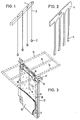
- Fig. 1 denotes the support rod for the support elements 2.
- the individual support elements 2 are connected to the support rod 1 by threads or thin rods 3. Despite the simple attachment to the threads or thin rods 3, the support elements 2 remain in their positions between the anode and cathode, since they do not float in the electrolyte.
- the support elements 2 can have any shape, e.g. be designed as a double cone or pyramid. However, balls or profile sections that are readily available or that can be produced for retrofitting are particularly advantageous.
- the length or the diameter of the support elements 2 is chosen to be smaller than the desired distance between the anode and cathode, advantageously approximately 5 mm smaller. So the differences in the cathode thicknesses etc. are taken into account, so that a flawless and easy insertion, movement and removal of the support elements 2 is possible at any time.
- the support elements 2 are preferably made of homogeneous plastic material, but they can also be fillers, e.g. Have quartz sand to make their production cheaper and / or increase their specific weight.
- FIG. 2 shows a summary of the elements 1, 2 and 3 from FIG. 1 to form a dimensionally stable handling unit 4 which has a comb-like appearance.
- the support elements 5 are preferably no longer spherical, cylindrical or prismatic, but wedge-shaped with an upward taper.
- the combination of the elements 1, 2 and 3 into a comb-like device 4 is particularly advantageous for handling and the formation of the supporting elements 5 in a wedge shape is particularly advantageous for preventing the formation of bridges on the supporting elements.
- the preparation of the comb-like device 4 can be done by simply gluing the corresponding individual parts, e.g. of plate cutouts, but also a production by casting or the like. possible.
- the total length of the comb-like device 4 is preferably not more than 4 m, since longer devices become too bulky.
- FIG. 3 shows two anodes 12 and 13 and a cathode sheet 8 arranged between the anodes 12 and 13, which is supported on the anodes 12 and 13 by means of the support elements 6 and 7.
- the support elements 6 and 7 are arranged unevenly on the two sides of the cathode sheet 8, once in the middle and once at the lower edge. They are held by threads or thin rods 15 and 16.
- the cathode sheet 8 is held at the top by the ear straps 9, which are pushed onto the cathode support rod 10.
- the cathode support rod 10 is placed in a manner not shown, like the ears 11 of the anodes, on busbars.
- the frame 14 drawn in broken lines is in turn placed on the cathode support rods 10.
- the servers unites a larger number of support elements 6 and 7 with their threads or thin rods 15 to form a handling unit.
- the frame 14 can be made of any material that does not conduct electricity, for example PVC.
- a thermal insulation layer is preferably placed on the frame 14, preferably in the form of a mat. Both fiber and foam mats can be used. It is important that their underside is impermeable to air and that their thermal insulation is so large that no H 20 condenses on their underside.
- the method according to the invention for the electrolytic deposition of metals proceeds as follows: cathode starting plates are inserted into the electrolyte in the usual way and then the fixing device is inserted, which can be changed in position from time to time.
- the electrolyte is optionally covered. At the latest after 2 to 3 days, but usually after 24 hours, the cathode has reached a stiffness that prevents further warping of the cathode.
- the fixation device is now removed and the deposition continues without the fixation device without problems until the desired final cathode thickness is reached.
- the method according to the invention using the device according to the invention results in an increase in the space-time yield, an increase in the current yield and a reduction in the residual amount with improved cathode quality. Furthermore, there is a reduced workload due to the elimination of the continuous interference suppression of the system and a saving in the thermocolor color. It can also advantageously be covered, which saves heating steam and results in a better indoor climate.
- the method and the device according to the invention were developed for copper refining.
- the invention is in no way limited to copper refining. It can be used wherever metals are electrolytically deposited on cathode sheets, e.g. in nickel or cobalt electrolysis. There are also considerable advantages when using inert cathode sheets, since the expensive titanium or stainless steel cathode sheets are made thinner and considerable investment costs can be saved.
Landscapes
- Chemical & Material Sciences (AREA)
- Engineering & Computer Science (AREA)
- Chemical Kinetics & Catalysis (AREA)
- Electrochemistry (AREA)
- Materials Engineering (AREA)
- Metallurgy (AREA)
- Organic Chemistry (AREA)
- Electrolytic Production Of Metals (AREA)
- Manufacture And Refinement Of Metals (AREA)
Priority Applications (1)
| Application Number | Priority Date | Filing Date | Title |
|---|---|---|---|
| AT80101438T ATE8668T1 (de) | 1979-03-29 | 1980-03-19 | Verfahren und vorrichtung zum elektrolytischen abscheiden von metallen, insbesondere kupfer. |
Applications Claiming Priority (2)
| Application Number | Priority Date | Filing Date | Title |
|---|---|---|---|
| DE2912524A DE2912524C2 (de) | 1979-03-29 | 1979-03-29 | Arbeitsverfahren und Vorrichtung zum elektrolytischen Abscheiden von Metallen, insbesondere Kupfer |
| DE2912524 | 1979-03-29 |
Publications (2)
| Publication Number | Publication Date |
|---|---|
| EP0017085A1 EP0017085A1 (de) | 1980-10-15 |
| EP0017085B1 true EP0017085B1 (de) | 1984-07-25 |
Family
ID=6066822
Family Applications (1)
| Application Number | Title | Priority Date | Filing Date |
|---|---|---|---|
| EP80101438A Expired EP0017085B1 (de) | 1979-03-29 | 1980-03-19 | Verfahren und Vorrichtung zum elektrolytischen Abscheiden von Metallen, insbesondere Kupfer |
Country Status (13)
| Country | Link |
|---|---|
| US (1) | US4319970A (enExample) |
| EP (1) | EP0017085B1 (enExample) |
| JP (1) | JPS55164090A (enExample) |
| AT (1) | ATE8668T1 (enExample) |
| AU (1) | AU534899B2 (enExample) |
| CA (1) | CA1186274A (enExample) |
| DE (1) | DE2912524C2 (enExample) |
| ES (1) | ES489994A1 (enExample) |
| FI (1) | FI66212C (enExample) |
| PL (1) | PL129235B1 (enExample) |
| SU (1) | SU1218928A3 (enExample) |
| YU (2) | YU83980A (enExample) |
| ZA (1) | ZA801445B (enExample) |
Families Citing this family (7)
| Publication number | Priority date | Publication date | Assignee | Title |
|---|---|---|---|---|
| DE3111628C2 (de) * | 1981-03-25 | 1983-07-14 | Hoechst Ag, 6230 Frankfurt | Elektrolysezelle |
| US4749464A (en) * | 1986-04-28 | 1988-06-07 | Technical Plastic T-R Ltd. | Non conductive edge strip for use on an electrolytic metal refining cathode |
| YU74987A (en) * | 1987-04-24 | 1989-08-31 | Aleksandar Despic | Electrochemical cell with movable electrode |
| FI125808B (en) * | 2012-03-09 | 2016-02-29 | Outotec Oyj | Anode and method for operating an electrolytic cell |
| CN104233369B (zh) * | 2013-06-17 | 2017-05-10 | 胡桂生 | 铜电解精炼阳极板下沿等间距固定装置 |
| CN105018972A (zh) * | 2014-04-21 | 2015-11-04 | 上海奇谋能源技术开发有限公司 | 一种降低电解槽电压的方法 |
| WO2018092103A1 (en) * | 2016-11-19 | 2018-05-24 | Jan Petrus Human | Electrodes for use in the electro-extraction of metals |
Family Cites Families (16)
| Publication number | Priority date | Publication date | Assignee | Title |
|---|---|---|---|---|
| US553464A (en) * | 1896-01-21 | hermite | ||
| US1313246A (en) * | 1919-08-19 | Electrolytic process and anode | ||
| US411042A (en) * | 1889-09-17 | kolle | ||
| US799061A (en) * | 1896-07-07 | 1905-09-12 | Carl Kellner | Electrolytic apparatus and electrodes therefor. |
| US745412A (en) * | 1896-12-08 | 1903-12-01 | Henry Blackman | Electrode. |
| US1209710A (en) * | 1916-07-07 | 1916-12-26 | Siemens Ag | Wire electrode for electrolytic purposes. |
| US1609771A (en) * | 1925-08-11 | 1926-12-07 | American Smelting Refining | Process and apparatus for electrolytic refining |
| US2536877A (en) * | 1947-10-17 | 1951-01-02 | Anaconda Copper Mining Co | Cathode |
| DE1202006B (de) * | 1964-03-19 | 1965-09-30 | Norddeutsche Affinerie | Verfahren zur elektrolytischen Gewinnung und Raffination von Schwermetallen, insbesondere Kupfer |
| GB1045816A (en) * | 1964-11-05 | 1966-10-19 | David J Evans Res Ltd | Improvements in or relating to electrodes for electrolytic cells |
| US3804724A (en) * | 1972-12-11 | 1974-04-16 | Ca Copper Refiners Ltd | Production of blanks used in the electrodeposition of strippable metal coatings |
| US3875041A (en) * | 1974-02-25 | 1975-04-01 | Kennecott Copper Corp | Apparatus for the electrolytic recovery of metal employing improved electrolyte convection |
| FI53463C (fi) * | 1975-04-10 | 1978-05-10 | Outokumpu Oy | Foerfarande och anordning foer avsoekning och avlaegsnande av kortslutningar i en elektrolysbassaeng |
| US4097354A (en) * | 1975-05-12 | 1978-06-27 | Ginatta Marco | Continuous process for electrolytic refining and electrowinning of elements and compounds |
| US3997421A (en) * | 1976-02-02 | 1976-12-14 | Cominco Ltd. | Top-mounted anode spacer clip |
| US4102769A (en) * | 1977-04-07 | 1978-07-25 | Seyl Robert G | Corrosion probe |
-
1979
- 1979-03-29 DE DE2912524A patent/DE2912524C2/de not_active Expired
-
1980
- 1980-03-12 ZA ZA00801445A patent/ZA801445B/xx unknown
- 1980-03-17 AU AU56506/80A patent/AU534899B2/en not_active Ceased
- 1980-03-19 FI FI800855A patent/FI66212C/fi not_active IP Right Cessation
- 1980-03-19 EP EP80101438A patent/EP0017085B1/de not_active Expired
- 1980-03-19 AT AT80101438T patent/ATE8668T1/de not_active IP Right Cessation
- 1980-03-26 CA CA000348496A patent/CA1186274A/en not_active Expired
- 1980-03-26 YU YU00839/80A patent/YU83980A/xx unknown
- 1980-03-26 US US06/134,090 patent/US4319970A/en not_active Expired - Lifetime
- 1980-03-27 ES ES489994A patent/ES489994A1/es not_active Expired
- 1980-03-28 PL PL1980223075A patent/PL129235B1/pl unknown
- 1980-03-28 SU SU802911252A patent/SU1218928A3/ru active
- 1980-03-28 JP JP3914480A patent/JPS55164090A/ja active Pending
-
1982
- 1982-10-07 YU YU02254/82A patent/YU225482A/xx unknown
Also Published As
| Publication number | Publication date |
|---|---|
| FI66212B (fi) | 1984-05-31 |
| DE2912524A1 (de) | 1980-10-09 |
| EP0017085A1 (de) | 1980-10-15 |
| PL223075A1 (enExample) | 1981-01-30 |
| FI800855A7 (fi) | 1980-09-30 |
| YU225482A (en) | 1983-02-28 |
| US4319970A (en) | 1982-03-16 |
| AU5650680A (en) | 1980-10-02 |
| SU1218928A3 (ru) | 1986-03-15 |
| ES489994A1 (es) | 1980-10-01 |
| FI66212C (fi) | 1984-09-10 |
| DE2912524C2 (de) | 1985-08-29 |
| ATE8668T1 (de) | 1984-08-15 |
| CA1186274A (en) | 1985-04-30 |
| YU83980A (en) | 1983-02-28 |
| AU534899B2 (en) | 1984-02-23 |
| ZA801445B (en) | 1980-12-31 |
| PL129235B1 (en) | 1984-04-30 |
| JPS55164090A (en) | 1980-12-20 |
Similar Documents
| Publication | Publication Date | Title |
|---|---|---|
| DE3245070C2 (de) | Vorrichtung zur genauen Einstellung der Anodenebene einer Zelle zur Herstellung von Aluminium durch Schmelzflußelektrolyse | |
| WO2012171129A2 (de) | Wärmetauscher, duschwanne und verfahren zur herstellung einer duschwanne | |
| EP2183409B1 (de) | Verfahren zum betreiben von kupfer-elektrolysezellen | |
| EP0017085B1 (de) | Verfahren und Vorrichtung zum elektrolytischen Abscheiden von Metallen, insbesondere Kupfer | |
| DE2508094A1 (de) | Verfahren und vorrichtung zum elektrolytischen abscheiden von metallen | |
| DE2244038C3 (de) | Verfahren und Vorrichtungen zum Herstellen von Flachglas | |
| DE642373C (de) | Verfahren und Vorrichtung zur elektrolytischen Verstaerkung von Metallblechen | |
| DE2828892C2 (de) | Monopolare Elektrolysezelle | |
| DE2624171C3 (de) | Vorrichtung zum Gewinnen von Aluminium durch Elektrolyse | |
| DE3908087A1 (de) | Verfahren und vorrichtung zur nachregulierung des polabstandes zum ausgleich des anodenabbrandes bei elektrolysezellen | |
| EP0117842B1 (de) | Befestigung von Anodenzapfen bzw.-spaten in einer Kohlenstoffanode | |
| CH649317A5 (de) | Elektrolysezelle mit kompensierten magnetfeldkomponenten. | |
| DE2143603C3 (de) | Zelle für die Gewinnung von Aluminium durch Elektrolyse von Aluminiumoxid im Schmelzfluß | |
| DE3841510C2 (de) | Hubeinrichtung zum gruppenweisen Behängen von Elektrolysebädern mit Elektroden | |
| DE2143602B2 (de) | Zelle für die Gewinnung von Aluminium durch Elektrolyse von Aluminiumoxid im Schmelzfluß | |
| DE2731908B1 (de) | Verfahren und Vorrichtung zum Herstellen von Aluminium | |
| DE3618588C2 (enExample) | ||
| DE1939917A1 (de) | Verfahren und Vorrichtung zur Herstellung von Floatglas | |
| DE865979C (de) | Verfahren zur Herstellung von schmied- und gluehbarem Nickel | |
| DE3024696C2 (de) | Elektrolysezelle zur Durchführung einer Raffinationselektrolyse | |
| DE3228536A1 (de) | Verfahren zur herstellung von duennem schichtglas mit hoher qualitaet nach dem schwimmprozess | |
| DE19940698C2 (de) | Elektrolyseanlage für die Metallgewinnung | |
| AT222453B (de) | Verfahren und Vorrichtung zur vorzugsweise kontinuierlichen einseitigen Anodisierung von Metallfolien oder- bändern | |
| DE2844708C2 (de) | Verfahren zur kontinuierlichen Galvanisierung eines Bandes aus porösem, nichtleitendem Material | |
| DE1596590C (de) | Verfahren und Vorrichtung zur Steue rung der Temperatur einer Schicht aus ge schmolzenem Glas auf einem Bad aus geschmol zenem Metall |
Legal Events
| Date | Code | Title | Description |
|---|---|---|---|
| PUAI | Public reference made under article 153(3) epc to a published international application that has entered the european phase |
Free format text: ORIGINAL CODE: 0009012 |
|
| AK | Designated contracting states |
Designated state(s): AT BE CH FR GB IT LU NL SE |
|
| 17P | Request for examination filed |
Effective date: 19810122 |
|
| ITF | It: translation for a ep patent filed | ||
| GRAA | (expected) grant |
Free format text: ORIGINAL CODE: 0009210 |
|
| AK | Designated contracting states |
Designated state(s): AT BE CH FR GB IT LU NL SE |
|
| PG25 | Lapsed in a contracting state [announced via postgrant information from national office to epo] |
Ref country code: NL Effective date: 19840725 |
|
| REF | Corresponds to: |
Ref document number: 8668 Country of ref document: AT Date of ref document: 19840815 Kind code of ref document: T |
|
| ET | Fr: translation filed | ||
| PGFP | Annual fee paid to national office [announced via postgrant information from national office to epo] |
Ref country code: BE Payment date: 19841231 Year of fee payment: 6 |
|
| NLV1 | Nl: lapsed or annulled due to failure to fulfill the requirements of art. 29p and 29m of the patents act | ||
| PG25 | Lapsed in a contracting state [announced via postgrant information from national office to epo] |
Ref country code: LU Free format text: LAPSE BECAUSE OF NON-PAYMENT OF DUE FEES Effective date: 19850331 Ref country code: CH Effective date: 19850331 |
|
| PLBE | No opposition filed within time limit |
Free format text: ORIGINAL CODE: 0009261 |
|
| STAA | Information on the status of an ep patent application or granted ep patent |
Free format text: STATUS: NO OPPOSITION FILED WITHIN TIME LIMIT |
|
| 26N | No opposition filed | ||
| REG | Reference to a national code |
Ref country code: CH Ref legal event code: PL |
|
| PGFP | Annual fee paid to national office [announced via postgrant information from national office to epo] |
Ref country code: AT Payment date: 19860317 Year of fee payment: 7 |
|
| PG25 | Lapsed in a contracting state [announced via postgrant information from national office to epo] |
Ref country code: AT Effective date: 19870319 |
|
| BERE | Be: lapsed |
Owner name: HUTTENWERKE KAYSER A.G. Effective date: 19870331 |
|
| PG25 | Lapsed in a contracting state [announced via postgrant information from national office to epo] |
Ref country code: SE Effective date: 19880320 |
|
| PG25 | Lapsed in a contracting state [announced via postgrant information from national office to epo] |
Ref country code: GB Free format text: LAPSE BECAUSE OF NON-PAYMENT OF DUE FEES Effective date: 19881118 |
|
| GBPC | Gb: european patent ceased through non-payment of renewal fee | ||
| PG25 | Lapsed in a contracting state [announced via postgrant information from national office to epo] |
Ref country code: FR Free format text: LAPSE BECAUSE OF NON-PAYMENT OF DUE FEES Effective date: 19881130 |
|
| REG | Reference to a national code |
Ref country code: FR Ref legal event code: ST |
|
| PG25 | Lapsed in a contracting state [announced via postgrant information from national office to epo] |
Ref country code: BE Effective date: 19890331 |
|
| EUG | Se: european patent has lapsed |
Ref document number: 80101438.2 Effective date: 19881201 |