EP0014491A1 - Double walled container protected against ignition and corrosion and method of making same - Google Patents
Double walled container protected against ignition and corrosion and method of making same Download PDFInfo
- Publication number
- EP0014491A1 EP0014491A1 EP80200034A EP80200034A EP0014491A1 EP 0014491 A1 EP0014491 A1 EP 0014491A1 EP 80200034 A EP80200034 A EP 80200034A EP 80200034 A EP80200034 A EP 80200034A EP 0014491 A1 EP0014491 A1 EP 0014491A1
- Authority
- EP
- European Patent Office
- Prior art keywords
- wall
- plastic
- double
- wire mesh
- walled container
- Prior art date
- Legal status (The legal status is an assumption and is not a legal conclusion. Google has not performed a legal analysis and makes no representation as to the accuracy of the status listed.)
- Granted
Links
- 238000005260 corrosion Methods 0.000 title claims description 7
- 230000007797 corrosion Effects 0.000 title claims description 7
- 238000004519 manufacturing process Methods 0.000 title claims description 7
- 239000004033 plastic Substances 0.000 claims abstract description 34
- 229920003023 plastic Polymers 0.000 claims abstract description 34
- 239000011152 fibreglass Substances 0.000 claims abstract description 13
- 238000000034 method Methods 0.000 claims abstract description 10
- 229910052782 aluminium Inorganic materials 0.000 claims description 15
- XAGFODPZIPBFFR-UHFFFAOYSA-N aluminium Chemical compound [Al] XAGFODPZIPBFFR-UHFFFAOYSA-N 0.000 claims description 15
- 239000011888 foil Substances 0.000 claims description 10
- 239000002985 plastic film Substances 0.000 claims description 8
- 229920006255 plastic film Polymers 0.000 claims description 8
- 239000000126 substance Substances 0.000 claims description 4
- 238000004873 anchoring Methods 0.000 claims description 2
- 239000000945 filler Substances 0.000 claims description 2
- 239000002245 particle Substances 0.000 claims description 2
- 238000000053 physical method Methods 0.000 claims description 2
- 239000010453 quartz Substances 0.000 claims description 2
- VYPSYNLAJGMNEJ-UHFFFAOYSA-N silicon dioxide Inorganic materials O=[Si]=O VYPSYNLAJGMNEJ-UHFFFAOYSA-N 0.000 claims description 2
- 239000010935 stainless steel Substances 0.000 claims description 2
- 229920001225 polyester resin Polymers 0.000 claims 2
- 239000004645 polyester resin Substances 0.000 claims 2
- 239000003990 capacitor Substances 0.000 claims 1
- 230000002787 reinforcement Effects 0.000 claims 1
- 229910001220 stainless steel Inorganic materials 0.000 claims 1
- 229920006337 unsaturated polyester resin Polymers 0.000 claims 1
- 238000004880 explosion Methods 0.000 abstract description 3
- 239000000088 plastic resin Substances 0.000 abstract 2
- 239000011248 coating agent Substances 0.000 abstract 1
- 238000000576 coating method Methods 0.000 abstract 1
- YXFVVABEGXRONW-UHFFFAOYSA-N Toluene Chemical compound CC1=CC=CC=C1 YXFVVABEGXRONW-UHFFFAOYSA-N 0.000 description 6
- 229920000728 polyester Polymers 0.000 description 6
- 238000010276 construction Methods 0.000 description 4
- 238000012544 monitoring process Methods 0.000 description 4
- 230000000694 effects Effects 0.000 description 3
- 238000003860 storage Methods 0.000 description 3
- 229910000831 Steel Inorganic materials 0.000 description 2
- 238000004026 adhesive bonding Methods 0.000 description 2
- 239000004568 cement Substances 0.000 description 2
- 238000004140 cleaning Methods 0.000 description 2
- 239000007788 liquid Substances 0.000 description 2
- 230000036961 partial effect Effects 0.000 description 2
- 238000009417 prefabrication Methods 0.000 description 2
- 239000011347 resin Substances 0.000 description 2
- 229920005989 resin Polymers 0.000 description 2
- 238000007789 sealing Methods 0.000 description 2
- 239000010959 steel Substances 0.000 description 2
- OKTJSMMVPCPJKN-UHFFFAOYSA-N Carbon Chemical compound [C] OKTJSMMVPCPJKN-UHFFFAOYSA-N 0.000 description 1
- 239000004593 Epoxy Substances 0.000 description 1
- LFQSCWFLJHTTHZ-UHFFFAOYSA-N Ethanol Chemical compound CCO LFQSCWFLJHTTHZ-UHFFFAOYSA-N 0.000 description 1
- 229920000426 Microplastic Polymers 0.000 description 1
- 239000000853 adhesive Substances 0.000 description 1
- 230000001070 adhesive effect Effects 0.000 description 1
- 239000000969 carrier Substances 0.000 description 1
- 230000015556 catabolic process Effects 0.000 description 1
- 239000002800 charge carrier Substances 0.000 description 1
- OGSYQYXYGXIQFH-UHFFFAOYSA-N chromium molybdenum nickel Chemical compound [Cr].[Ni].[Mo] OGSYQYXYGXIQFH-UHFFFAOYSA-N 0.000 description 1
- 238000011161 development Methods 0.000 description 1
- 230000018109 developmental process Effects 0.000 description 1
- 238000007599 discharging Methods 0.000 description 1
- 230000003670 easy-to-clean Effects 0.000 description 1
- 230000005611 electricity Effects 0.000 description 1
- 238000007786 electrostatic charging Methods 0.000 description 1
- 239000002360 explosive Substances 0.000 description 1
- 239000004744 fabric Substances 0.000 description 1
- 239000003365 glass fiber Substances 0.000 description 1
- 239000003292 glue Substances 0.000 description 1
- 229910002804 graphite Inorganic materials 0.000 description 1
- 239000010439 graphite Substances 0.000 description 1
- 238000007373 indentation Methods 0.000 description 1
- 239000004922 lacquer Substances 0.000 description 1
- 230000000873 masking effect Effects 0.000 description 1
- 239000000463 material Substances 0.000 description 1
- 229910052751 metal Inorganic materials 0.000 description 1
- 239000002184 metal Substances 0.000 description 1
- 229920001084 poly(chloroprene) Polymers 0.000 description 1
- 238000002360 preparation method Methods 0.000 description 1
- 230000001681 protective effect Effects 0.000 description 1
- 238000005086 pumping Methods 0.000 description 1
- 230000002829 reductive effect Effects 0.000 description 1
- 238000009418 renovation Methods 0.000 description 1
- 230000035945 sensitivity Effects 0.000 description 1
- 239000007787 solid Substances 0.000 description 1
- 125000006850 spacer group Chemical group 0.000 description 1
- 230000003068 static effect Effects 0.000 description 1
- 239000000758 substrate Substances 0.000 description 1
- 239000012808 vapor phase Substances 0.000 description 1
Images


Classifications
-
- B—PERFORMING OPERATIONS; TRANSPORTING
- B65—CONVEYING; PACKING; STORING; HANDLING THIN OR FILAMENTARY MATERIAL
- B65D—CONTAINERS FOR STORAGE OR TRANSPORT OF ARTICLES OR MATERIALS, e.g. BAGS, BARRELS, BOTTLES, BOXES, CANS, CARTONS, CRATES, DRUMS, JARS, TANKS, HOPPERS, FORWARDING CONTAINERS; ACCESSORIES, CLOSURES, OR FITTINGS THEREFOR; PACKAGING ELEMENTS; PACKAGES
- B65D90/00—Component parts, details or accessories for large containers
- B65D90/22—Safety features
- B65D90/46—Arrangements for carrying off, or preventing the formation of electrostatic charges
-
- B—PERFORMING OPERATIONS; TRANSPORTING
- B65—CONVEYING; PACKING; STORING; HANDLING THIN OR FILAMENTARY MATERIAL
- B65D—CONTAINERS FOR STORAGE OR TRANSPORT OF ARTICLES OR MATERIALS, e.g. BAGS, BARRELS, BOTTLES, BOXES, CANS, CARTONS, CRATES, DRUMS, JARS, TANKS, HOPPERS, FORWARDING CONTAINERS; ACCESSORIES, CLOSURES, OR FITTINGS THEREFOR; PACKAGING ELEMENTS; PACKAGES
- B65D90/00—Component parts, details or accessories for large containers
- B65D90/02—Wall construction
- B65D90/028—Wall construction hollow-walled, e.g. double-walled with spacers
Definitions
- the present invention relates to a double-walled container for a combustible medium, consisting of an outer container wall and a glass fiber-reinforced plastic wall which is arranged at a distance from it and at least partially provided with electrically conductive substances and faces the medium to reduce the risk of ignition and corrosion.
- the tightness of the plastic wall can be checked by physical measurement methods.
- Double-walled containers in particular tanks, are increasingly being used to store flammable liquids such as petrol, alcohol, toluene, etc.
- plastic double-jacket systems have proven themselves for several years. These have the advantage of high corrosion resistance and can also be bonded relatively easily gas and liquid-tight in concrete, metal or tanks made of organic substances.
- Such linings are difficult to apply in double-walled containers and cause sealing problems. In addition, they cannot be walked on or entail the risk of injuring or detaching the electrically conductive layer.
- the electrical resistance of the surface of the plastic walls can be reduced by means of electrically conductive lacquer layers.
- these have the disadvantages of poor adhesion to the substrate, poor and poor conductivity and inadequate chemical and mechanical resistance. For the same reason, walking through the tank cannot be held responsible.
- the invention has for its object in particular to provide a double-walled container of the type mentioned, which does not have the disadvantages of the known and which prevents the occurrence of disruptive or dangerous electrostatic charges on the surface of the plastic wall due to the low surface resistance in advance.
- the invention specified in claim 1 has the advantage of a type of Faraday cage in the surface of the plastic wall facing the medium to be stored and thus prevents the occurrence of electrical potential differences between mesh elements at any location in the container. Sinking in the wire mesh results in good mechanical fixation of the wire mesh, without impairing the mechanical stability and crack sensitivity of the plastic wall, and due to a large number of metallic contact points with the medium, the medium can be grounded optimally.
- the size of the individual wire meshes can be adapted to the flash point, the explosion limit, the ignition temperature, the minimum ignition energy and the physical state variables of the medium.
- Another criterion is the type of operational use, in particular the flow rate of the medium, the type of filling and pumping, and the choice of cleaning methods when the container is fully and / or partially emptied.
- the arrangement can be integrated into existing tank designs and does not in any way affect the usual leak monitoring methods used.
- the embodiment according to claim 2 allows the prefabrication of plastic walls and has proven itself especially in the construction of tank farms.
- the embodiment according to claim 3 results in particularly reliable tight walls and allows the introduction of mechanically pretensionable galvanic connections between the individual tracks and the connecting lines of the earth potential.
- the advantage of the embodiment according to claim 4 lies in the fact that reliable and easily manufactured double-wall systems result.
- the embodiment according to claim 5 increases the mechanical strength of the wall and allows safe access to tank rooms, which is particularly important for cleaning and monitoring purposes.
- the advantage of an embodiment designed according to claim 6 is the high effectiveness in terms of dissipating electrostatic charges.
- the layer structure described in claim 7 has proven itself particularly in large tank systems and is suitable for container walls of a wide variety of materials.
- the advantage of the embodiment listed in claim 8 is its high resistance to corrosion and insensitivity to many aggressive-acting explosive media.
- a container produced using the method set out in claim 9 results in surfaces that are easy to clean and the particular advantage of economy.
- the further variant according to claim 10 also enables the production of curved surfaces on construction sites.
- the invention or the method according to the invention can be combined with other systems for discharging electrical charges and opens up a large number of new applications opportunities.
- Fig. 1 denotes a wire mesh.
- This wire mesh 1 is flexible and sumped with at least one wire over half the wire circumference in a hardening plastic 3, which is part of a layered plastic wall 2.
- a sunk node 1a of a wire mesh can be seen from FIG.
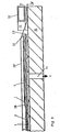
- FIG. 3 A preferred exemplary embodiment of a double-walled tank is shown in partial section in FIG. 3. This is a toluene container with a container wall 4 made of steel.
- the container wall 4 together with the plastic wall 2 held at a distance of a few millimeters, forms a double wall system.
- the plastic wall 2 has on it. an aluminum foil 5 on the side facing the container wall 4. Both walls 2 and 4 are spaced apart by pressure-resistant aluminum knobs 6.
- On the aluminum foil 5 is a glass fiber reinforced plastic (GRP) 7, which in turn is provided with individual webs of a wire mesh 1,1 '.
- GRP glass fiber reinforced plastic
- a busbar 8 connects individual tracks of the wire mesh 1, 1 'and is fixed via force introduction elements 9.
- the tank container is closed by a tank cap 10 fastened by means of screws (not shown).
- a grounding clamp 11 is screwed into the tank cap 10; an earth wire 12 is attached to this, which is led to the busbar 8 via a monitoring connection 13 (e.g. vacuum or protective gas connection).
- a monitoring connection 13 e.g. vacuum or protective gas connection.
- the aluminum foil 5 is likewise galvanically connected to the monitoring connection 13 by means of a contact disk 14 and is thus conductive to the grounding terminal 11.
- the steel jacket of the container wall 4 is connected to earth potential E in the present example.
- pure polyester 192 MV, Gurder company
- the aluminum knobs are reinforced with a hardening filler - inside - by quartz particles and UP resin in a mixed weight ratio of 52% to 48%.
- a flat plate made of corrosion-resistant steel of the chromium-nickel-molybdenum type (V4A) serves as the busbar 8
- Figures 4 and 5 represent overlaps of the wire nets 1 and 1 'and at the same time serve to explain the layer structure and the production of double-walled containers.
- an epoxy layer 22 (Etoplate, Gurder) is applied to the inside of the container wall 4 as protection against corrosion of the jacket and for the selective bonding of the pads 6 of the aluminum foil 5.
- the prefabricated and cut to length plastic wall 2 has on its upper side a loose bent piece of the wire mesh 1.
- the force introduction element 9 is placed with its flange 15 on a GRP spacer cam 24 and glued into a GRP laminate 25 with its star-shaped anchoring wires 16.
- the GRP laminate 25 with polyester putty 23 is leveled out to the GRP 7 1 of the wall 2 and then sanded.
- the wire mesh 1 which is in position I during assembly is now bent in the direction of the arrow in position II and electrically connected to its mutual end part via the busbar 8.
- the GRP 7 'in FIG. 5 are designed with butt joints 7a, which are positively connected by means of polyester cement 23; likewise the aluminum foil 5.
- the aluminum knobs 6 ' have a height of 5 mm; the wire mesh 1 'is merely sumped into polyester at its nodes 1a.
- the vacuum pump is switched off, the plastic films 28, 28 'are removed and there is a ready-to-install sheet of a tank wall.
- the bottoms of tanks are also produced in an analogous manner.
- a plastic hose made to the internal dimensions of the tank is advantageously placed on the coated wall 2 prepared in the tank, sealed on the edges, and centrally with the introduction of a vacuum connection, and thus the wire mesh 1 is blown in.
- the particular advantage of the method according to the invention is that commercial wire mesh is used can and that walls can also be produced on construction sites to suit individual needs.
- the invention described above is not limited to use in liquid tanks, but is suitable for any containers per se, for example also silos, laboratory containers, etc.
- the subject of the invention can also be used for the storage of solid bodies (plastic granules, etc.).
Landscapes
- Engineering & Computer Science (AREA)
- Mechanical Engineering (AREA)
- Details Of Rigid Or Semi-Rigid Containers (AREA)
- Laminated Bodies (AREA)
- Preventing Corrosion Or Incrustation Of Metals (AREA)
- Filling Or Discharging Of Gas Storage Vessels (AREA)
- Prevention Of Electric Corrosion (AREA)
Abstract
Description
Die vorliegende Erfindung bezieht sich auf einen doppelwandigen Behälter für ein brennbares Medium, bestehend aus einer äusseren Behälterwandung und einer in einem Abstand von dieser angeordneter, wenigstens partiell mit elektrisch leitenden Stoffen versehenen, dem Medium zugewandter, glasfaserverstärkter Kunststoffwandung zur Reduktion der Zünd-und Korrosionsgefahr, wobei die Dichtigkeit der Kunststoffwandung durch physikalische Messverfahren überprüfbar ist.The present invention relates to a double-walled container for a combustible medium, consisting of an outer container wall and a glass fiber-reinforced plastic wall which is arranged at a distance from it and at least partially provided with electrically conductive substances and faces the medium to reduce the risk of ignition and corrosion. the tightness of the plastic wall can be checked by physical measurement methods.
Doppelwandige Behälter, insbesondere Tanks finden in zunehmendem Masse Anwendung zur Lagerung von brennbaren Flüssigkeiten wie Benzin, Alkohol, Toluol etc. Im Öltankbau sowie bei der Sanierung von älteren öltankanlagen haben sich bereits seit einigen Jahren Doppelmantelsysteme aus Kunststoff bewährt. Diese weisen den Vorzug einer hohen Korrosionsfestigkeit auf und lassen sich auch nachträglich in Beton, Metall oder aus organischen Stoffen bestehenden Tanks relativ leicht gas- und flüssigkeitsdicht verkleben.Double-walled containers, in particular tanks, are increasingly being used to store flammable liquids such as petrol, alcohol, toluene, etc. In the construction of oil tanks and in the renovation of older oil tank systems, plastic double-jacket systems have proven themselves for several years. These have the advantage of high corrosion resistance and can also be bonded relatively easily gas and liquid-tight in concrete, metal or tanks made of organic substances.
Nachteilig wirkt sich dagegen der hohe elektrische Oberflachenwiderstand von Kunststoffen beim praktischen Einsatz derartiger Behälter aus. Betriebsbedingte mechanische Bewegung des zu lagernden Mediums verursacht eine Bewegung von Elektrizitätsträgern unterschiedlicher Ladungen und führt somit zur elektrostatischen Aufladung der Kunststoffwandung. Wird nun beispielsweise bei einem Tank zur Vorbereitung des Füllens ein auf einem anderen Potential liegender Ladungsträger (Rohr etc.) in den Tankraum eingebracht, so kann dadurch die Durchschlagsfeldstärke der Luft- oder der Dampfphase überschritten werden, so dass die nun plötzlich entladene elektrische Energie zum Brand oder zur Explosion des Tankinhaltes führt.In contrast, the high electrical surface resistance of plastics has a disadvantageous effect when such containers are used in practice. Operational mechanical movement of the medium to be stored causes movement of electricity carriers of different charges and thus leads to electrostatic charging of the plastic wall. If, for example, a charge carrier (pipe, etc.) lying at a different potential is introduced into the tank space in preparation for filling, the breakdown field strength of the air or vapor phase can be exceeded, so that the suddenly suddenly discharged electrical energy for Fire or explosion of the tank contents.
Zur Vermeidung der Zündgefahr bei gewickelten GrK-Lagertanks mit gepressten Böden ist es bekannt (Kunststoffe, 1969, Bd. 59, Heft 12, Seite 842), den Oberflächenwiderstand der Innenwandung durch Einkleben einer leitenden Vliesschicht und Einkleben der Böden mit leitfähigem Kleber, zu reduzieren. Als Variante dieser Lösung gilt das vollständige Einbetten eines speziellen Drahtgewebes im zylinderförmigen Bereich des Lagertanks. Dabei sind die seitlichen Enden des Gewebes in einer leitenden Graphit/Harz-Schicht eingebettet und mit der Klebefläche der mit dem leitenden Vlies versehenen Böden verbunden.In order to avoid the risk of ignition in the case of wound GrK storage tanks with pressed bottoms, it is known (Kunststoffe, 1969, Vol. 59, No. 12, page 842) to reduce the surface resistance of the inner wall by gluing in a conductive fleece layer and gluing the bottoms in with conductive glue . A variant of this solution is the complete embedding of a special wire mesh in the cylindrical area of the storage tank. The lateral ends of the fabric are embedded in a conductive graphite / resin layer and connected to the adhesive surface of the floors provided with the conductive fleece.
Derartige Auskleidungen lassen sich in doppelwandigen Behältern nur schwierig anbringen und rufen Dichtungsprobleme hervor. Ausserdem lassen sie sich nicht begehen oder bringen dabei die Gefahr des Verletzens bzw. des Ablösens der elektrisch leitenden Schicht mit sich.Such linings are difficult to apply in double-walled containers and cause sealing problems. In addition, they cannot be walked on or entail the risk of injuring or detaching the electrically conductive layer.
Eine Reduktion des elektrischen Widerstandes der Oberfläche der Kunststoffwandungen kann grundsätzlich durch elektrisch leitende Lackschichten erfolgen. Diese weisen jedoch den Nachteil einer schlechten Haftung auf dem Untergrund, mangelhafter und schlechter Leitfähigkeit sowie einer ungenügenden chemischen und mechanischen Beständigkeit auf. Aus dem gleichen Grund kann ein Begehen des Tanks nicht verantwortet werden.In principle, the electrical resistance of the surface of the plastic walls can be reduced by means of electrically conductive lacquer layers. However, these have the disadvantages of poor adhesion to the substrate, poor and poor conductivity and inadequate chemical and mechanical resistance. For the same reason, walking through the tank cannot be held responsible.
Der Erfindung liegt insbesondere die Aufgabe zugrunde, einen doppelwandigen Behälter der eingangs genannten Art zu schaffen, welcher die beschriebenen Nachteile des Bekannten nicht aufweist und an der Oberfläche der Kunststoffwandung das Auftreten von störenden oder gefährlichen elektrostatischen Ladungen aufgrund des niederen Oberflachemmiderstandes im vornhinein verunmöglicht.The invention has for its object in particular to provide a double-walled container of the type mentioned, which does not have the disadvantages of the known and which prevents the occurrence of disruptive or dangerous electrostatic charges on the surface of the plastic wall due to the low surface resistance in advance.
Die im Anspruch 1 angegebene Erfindung weist den Vorteil einer Art Faraday-Käfig, in der dem zu lagernden Medium zugewandten Oberfläche der Kunststoffwandung auf und verhindert damit das Entstehen von elektrischen Potentialunterschieden zwischen Maschenelementen an beliebigen Orten im Behälter. Durch ein Einsumpfen des Drahtgitters ergibt sich eine gute mechanische Fixation der Gitterdrähte, ohne Beeinträchtigung der mechanischen Stabilität und Rissempfindlichkeit der Kunststoffwandung sowie aufgrund einer Vielzahl metallischer Kontaktstellen mit dem Medium eine optimale Erdungsmöglichkeit des Mediums.The invention specified in
Die Grösse der einzelnen Drahtmaschen kann dabei dem Flammpunkt,der Explosionsgrenze, der Zündtemperatur, der Mindestzündenergie und den physikalischen Zustandsgrössen des Mediums angepasst werden. Ein weiteres Kriterium stellt zudem die Art des betriebsmässigen Einsatzes, insbesondere Strömungsgeschwindigkeit des Mediums, Art des Einfüllens und Abpumpens sowie die Wahl der Reinigungsverfahren bei vollem und/oder teilweise entleertem Behälter dar.The size of the individual wire meshes can be adapted to the flash point, the explosion limit, the ignition temperature, the minimum ignition energy and the physical state variables of the medium. Another criterion is the type of operational use, in particular the flow rate of the medium, the type of filling and pumping, and the choice of cleaning methods when the container is fully and / or partially emptied.
Die Anordnung lässt sich in bestehende Tankkonstruktionen integrieren und beeinträchtigt in keiner Weise die üblichen verwendeten Lecküberwachungsverfahren.The arrangement can be integrated into existing tank designs and does not in any way affect the usual leak monitoring methods used.
Vorteilhafte Weiterbildungen der Erfindung sind in den Unteransprüchen beschrieben.Advantageous developments of the invention are described in the subclaims.
Die Ausführungsform nach Anspruch 2 lässt die Vorfabrikation von Kunststoffwandungen zu und hat sich vor allem beim Bau von Tanklagern bewährt.The embodiment according to
Die Ausgestaltung nach Anspruch 3 ergibt besonders zuverlässig dichte Wandungen und erlaubt das Einbringen von mechanisch vorspannbaren galvanischen Verbindungen zwischen den einzelnen Bahnen und den Anschlussleitungen des Erd- potentials.The embodiment according to
Der Vorteil der Ausführungsform gemäss Anspruch 4 liegt darin, dass sich betriebssichere und leicht herstellbare Doppelwandsysteme ergeben.The advantage of the embodiment according to claim 4 lies in the fact that reliable and easily manufactured double-wall systems result.
Die Ausgestaltung nach Anspruch 5 erhöht die mechanische Beanspruchbarkeit der Wandung und lässt ein sicheres Begehen von Tankräumen zu, was vor allem für Reinigungs-und Überwachungszwecke sehr wichtig ist.The embodiment according to
Der Vorteil einer nach Anspruch 6 ausgestalteten Ausführungsform ist die hohe Wirksamkeit in Bezug auf die Ableitung elektrostatischer Ladungen.The advantage of an embodiment designed according to
Der in Anspruch 7 beschriebene Schichtaufbau hat sich vor allem in Grosstankanlagen bewährt und ist für Behälterwandungen verschiedenster Materialien geeignet.The layer structure described in claim 7 has proven itself particularly in large tank systems and is suitable for container walls of a wide variety of materials.
Der Vorteil der in Anspruch 8 aufgeführten Ausführungsform besteht in ihrer hohen Korrosionsfestigkeit und Unempfindlichkeit gegenüber vielen, aggressiv wirkenden explosionsgefährlichen Medien.The advantage of the embodiment listed in
Ein unter Einbezug des in Anspruch 9 ausgeführten Verfahrens hergestellter Behälter ergibt leicht zu reinigende Oberflächen und den besonderen Vorteil der Wirtschaftlichkeit.A container produced using the method set out in
Die weitere Variante nach Anspruch 10 ermöglicht auch die Herstellung bombierter Flächen auf Baustellen.The further variant according to claim 10 also enables the production of curved surfaces on construction sites.
Die Erfindung bzw. das erfindungsgemässe Verfahren kann mit anderen Systemen zur Ableitung elektrischer Ladungen kombiniert werden und eröffnet eine Vielzahl neuer Applikationsmöglichkeiten.The invention or the method according to the invention can be combined with other systems for discharging electrical charges and opens up a large number of new applications opportunities.
Der Erfindungsgegenstand sowie das erfindungsgemässe Verfahren werden im folgenden anhand schematischer Zeichnungen naher erläutert.The subject matter of the invention and the method according to the invention are explained in more detail below with the aid of schematic drawings.
Es zeigt:
- Fig. 1, eine Kunststoffwandung mit eingesumpftem Drahtgitter,
- Fig. 2, eine Variante der Anordnung Fig. 1 mit eingesumpften Knotenpunkten,
- Fig. 3, einen doppelwandigen Tank mit einzelnen Bahnen des Drahtgitters in einer Teilschnitt-Darstellung,
- Fig. 4, einen Schnitt durch eine Tankwandung an einer ebenen Überlappungsstelle,
- Fig. 5, einen Schnitt einer Tankwandung an einer gekrümmten Überlappungsstelle und
- Fig. 6, das Herstellungsverfahren für Kunststoffwandungen am Beispiel vorfabrizierter einzelner Bahnen.
- 1, a plastic wall with sunk wire mesh,
- 2, a variant of the arrangement of FIG. 1 with sunk nodes,
- 3, a double-walled tank with individual webs of the wire mesh in a partial sectional view,
- 4 shows a section through a tank wall at a flat overlap point,
- 5 shows a section of a tank wall at a curved overlap point and
- Fig. 6, the manufacturing process for plastic walls using the example of prefabricated individual webs.
In Fig. 1 ist mit 1 ein Drahtgitter bezeichnet. Dieses Drahtgitter 1 ist flexibel und mit wenigstens einem Draht über die Hälfte des Drahtumfangs in einem aushärtenden Kunststoff 3 eingesumpft, welcher Bestandteil einer schichtartig aufgebauten Kunststoffwandung 2 ist.In Fig. 1, 1 denotes a wire mesh. This
Aus Fig. 2 ist ein eingesumpfter Knotenpunkt 1a eines Drahtgitters ersichtlich.A sunk node 1a of a wire mesh can be seen from FIG.
Die Kunststoffwandungen 2, 2' können unterschiedliche Dikken aufweisen, verschiedenartig laminiert sein und einen dem zu lagernden Medium konformen Kunststoff 3 aufweisen.The
Ein bevorzugtes Ausführungsbeispiel eines doppelwandigen Tanks zeigt im Teilschnitt Fig. 3. Hierbei handelt es sich um einen Toluolbehälter mit einer.Behälterwandung 4 aus Stahl.A preferred exemplary embodiment of a double-walled tank is shown in partial section in FIG. 3. This is a toluene container with a container wall 4 made of steel.
Die Behälterwandung 4 bildet zusammen mit der in einem Abstand von einigen Millimetern gehaltenen Kunststoffwandung 2 ein Doppelwandsystem. Die Kunststoffwandung 2 weist auf ihrer. der Behälterwandung 4 zugewandten Seite eine Aluminiumfolie 5 auf. Distanziert sind beide Wandungen 2 und 4 durch druckbelastbare Aluminiumnoppen 6. Auf der Aluminiumfolie 5 befindet sich ein glasfaserverstärkter Kunststoff (GFK) 7, welcher seinerseits mit einzelnen Bahnen eines Drahtgitters 1,1' versehen ist. Das Drahtgitter 1 bzw. 1' ist zumindest an seinen Knotenpunkten 1a bzw. 1a verankert im Kunststoff 3, vgl. Fig. 2.The container wall 4, together with the
Eine Sammelschiene 8 verbindet einzelne Bahnen des Drahtgitters 1, 1' und ist über Krafteinleitungselemente 9 fixiert.A
Der Tankbehälter ist durch einen mittels Schrauben (nicht dargestellt) befestigten Tankdeckel 10 abgeschlossen. Im Tankdeckel 10 ist eine Erdungsklemme 11 eingeschraubt; an dieser ist eine Erdungslitze 12 befestigt, welche über einen Überwachungsanschluss 13 (z.B. Vakuum- oder Schutzgasanschluss) zur Sammelschiene 8 geführt ist.The tank container is closed by a
Die Aluminiumfolie 5 ist ebenfalls durch eine Kontaktscheibe 14 galvanisch mit dem Überwachungsanschluss 13 verbunden und somit zur Erdungsklemme 11 leitend.The
Der Stahlmantel der Behälterwandung 4 ist im vorliegenden Beispiel auf Erdpotential E gelegt.The steel jacket of the container wall 4 is connected to earth potential E in the present example.
Die Drahtgitter 1, 1' bestehen aus korrosionsbeständigem Chrom-Nickel-Draht (V2A) von 0,5 mm Durchmesser und 19 mm Maschenweite. Der Abstand zwischen den einzelnen Bahnen des Drahtgitters beträgt weniger als 10 cm. Als aushärtender Kunststoff hat sich im vorliegenden Fall Reinpolyester (192 MV, Firma Mäder) bewährt. Die Aluminiumnoppen sind mittels einer aushärtenden Spachtelmasse - im Inneren - durch Quarzteilchen und UP-Harz im Gew.-Mischverhältnis 52% zu 48% armiert. Als Sammelschiene 8 dient eine flache Platte aus korrosionsbeständigem Stahl des Chrom-Nickel-Molybdän-Typs (V4A)The
In den folgenden Figuren sind wiederum gleiche Funktionsteile mit gleichen Bezugsziffern versehen.In the following figures, the same functional parts are again provided with the same reference numbers.
Die Figuren 4 und 5 stellen Überlappungsstellen der Drahtnetze 1 bzw. 1' dar und dienen gleichzeitig zur näheren Erläuterung des Schichtaufbaus und der Herstellung von doppelwandigen Behältern.Figures 4 and 5 represent overlaps of the wire nets 1 and 1 'and at the same time serve to explain the layer structure and the production of double-walled containers.
Gemäss Fig. 4 ist als Korrosionsschutz des Mantels und zur punktuellen Klebung der Koppen 6 der Aluminiumfolie 5 eine Epoxidschicht 22 (Etoplate, Fa. Mäder) auf die Innenseite der Behältervandung 4 aufgebracht. Die vorgefertigte und auf Mass abgelängte Kunststoffwandung 2 weist an ihrer einen oberen Seite ein loses abgebogenes Stück des Drahtgitters 1 auf. Das Krafteinleitungselement 9 ist mit seinem Flansch 15 auf einem GFK-Distanznocken 24 aufgesetzt und mit seinen sternförmig angeordneten Verankerungsdrähten 16 in ein GFK-Laminat 25 eingeklebt. Auf den oberen und unteren Längsseiten ist das GFK-Laminat 25 mit Polyesterkitt 23 auslaufend zum GFK 71 der Wandung 2 verspachtelt und anschliessend verschliffen. Das Ganze ist durch eine Überlaminierung 26 flüssigkeitsdicht abgeschlossen; daraus ragt eine Gewindebüchse 17 heraus, in welche ein Gewindebolzen 18 eingeschraubt, drehfixiert und mittels Polyesterkitt 23 einseitig abgeschlossen ist..According to FIG. 4, an epoxy layer 22 (Etoplate, Mäder) is applied to the inside of the container wall 4 as protection against corrosion of the jacket and for the selective bonding of the
Das während der Montage in Position I befindliche Drahtgitter 1 wird nun in Pfeilrichtung in Position II abgebogen und mit seinem gegenseitigen Endteil über die Sammelschiene 8 galvanisch verbunden.The
Zur mechanischen Vorspannung dienen eine auf die Sammelschiene 8 drückende Spannhülse 19 mit Unterlagscheibe 20 und Mutter 21.A clamping
Die Anordnung nach Fig. 5 erzielt grundsätzlich dieselbe Wirkung; aufgrund der gewölbten Behälterwandung 4 wird jedoch auch bei vergleichsweise mit 9 kleinerem Krafteinleitungselement 9' eine sehr gute Federwirkung der Sammelschiene 8' erzielt.5 basically achieves the same effect; due to the curved container wall 4, however, a very good spring effect of the busbar 8 'is achieved even when the force introduction element 9' is comparatively smaller 9.
Gegenüber Fig. 4 sind bei Fig. 5 die GFK 7' mit Stossfugen 7a ausgeführt, welche mittels Polyesterkitt 23 formschlüssig verbunden sind; ebenso die Aluminiumfolie 5.Compared to FIG. 4, the GRP 7 'in FIG. 5 are designed with butt joints 7a, which are positively connected by means of
In dieser Variante weisen die Aluminiumnoppen 6' eine Höhe von 5 mm auf; das Drahtgitter 1' ist lediglich an seinen Knotenpunkten 1a in Polyester eingesumpft.In this variant, the aluminum knobs 6 'have a height of 5 mm; the wire mesh 1 'is merely sumped into polyester at its nodes 1a.
Bei der Herstellung doppelwandiger Behälter hat sich die Hassvorfabrikation . der Kunststoffwandung 2 in Form von einzelnen zugeschnittenen Bahnen sehr bewährt.In the manufacture of double-walled containers, there has been hate prefabrication. the
Diese werden zweckmässigerweise auf einem an sich bekannten Vakuumtisch 33, Fig. 6, hergestellt.These are expediently produced on a vacuum table 33, FIG. 6, known per se.
Auf die Aluminiumfolie 5 (0,05 mm Dicke) und die darauf geklebten GFK-Laminate 7 (Glasfasergew. 2 x 450g/m2) ist ein aushärtender Kunststoff 3 (Rein-Polyester 192 MV) aufgebracht. Je nach gewünschter Einsumpftiefe sind 180 g/m2 bis 700 g/m2 Kunststoff 3 aufgebracht; der Kunststoff ist randseitig durch ein Abdeckband 29 begrenzt. Auf diese Schicht wird nun ein zugeschnittenes Drahtgitter 1 (V2A-Draht), welches an einer Knickstelle 30 um ein Stück Kunststoffolie 28 (PVC) umgelegt ist, positioniert.On the aluminum foil 5 (0.05 mm thickness) and the GFK laminates 7 (glass fiber weight 2 x 450 g / m 2 ) glued thereon a curing plastic 3 (pure polyester 192 MV) applied. Depending on the desired sump depth, 180 g / m 2 to 700 g / m 2 of plastic 3 are applied; the plastic is delimited on the edge by a masking
Das Ganze wird nun durch eine weitere Kunststoffolie 28' (PVC-Vakuumfolie)abgedeckt. Auf der über die Kunststoffwandung 2 hinausragenden Randpartie wird anschliessend ein Dichtstreifen aus Neopren-Gummi gelegt, welcher durch einen umlaufenden Bohlprofilrahmen 32 beschwert ist.The whole is now covered by another plastic film 28 '(PVC vacuum film). A sealing strip made of neoprene rubber is then placed on the edge portion projecting beyond the
Durch ein am Anschluss 34 mittels einer starken Vakuumpumpe erzeugtes Vakuum V wird die Kunststoffolie 28' durch den statischen Atmosphärendruck gleichmässig belastet und bewirkt ein regelmassiges Einsumpfen des Drahtgitters 1 im Kunststoff 3.By means of a vacuum V generated at the
Nach einer Aushärtezeit von ca. 0,8 h werden die Vakuumpumpe abgeschaltet, die Kunststoffolien 28, 28' entfernt und es liegt eine einbaufertige Bahn einer Tankwandung vor.After a curing time of approx. 0.8 h, the vacuum pump is switched off, the
In analoger Weise werden ebenfalls die Böden von Tanks hergestellt.The bottoms of tanks are also produced in an analogous manner.
Bei bombierten Böden B wird jedoch vorteilhafterweise ein auf das Innenmass des Tanks gefertigter Kunststoffschlauch auf die im Tank vorbereitete, beschichtete Wandung 2 aufgelegt, randseitig,und zentral unter Einführung eines Vakuum-Anschlusses wurstartig, abgedichtet und damit das Drahtgitter 1 eingesuxpft.In the case of cambered bottoms B, however, a plastic hose made to the internal dimensions of the tank is advantageously placed on the
Der besondere Vorteil des erfindungsgemässen Verfahrens besteht darin, dass handelsübliche Drahtgitter verwendet werden können und dass dadurch auch auf Baustellen den individuellen Bedürfnissen angepasste Wandungen herstellbar sind.The particular advantage of the method according to the invention is that commercial wire mesh is used can and that walls can also be produced on construction sites to suit individual needs.
Es sei darauf hingewiesen, dass die vorstehend beschriebene Erfindung nicht auf die Anwendung in Flüssigkeitstanks beschränkt ist, sondern für an sich beliebige Behälter, beispielsweise auch Silos, Laborbehälter etc. geeignet ist. Je nach dem Grad der gewählten Einsumpfung, Maschenweite, Drahtstärke und Art des Drahtgitters lässt sich der Erfindungsgegenstand auch zur Lagerung von Festkörpern (Kunststoffgranulaten etc.) einsetzen.It should be pointed out that the invention described above is not limited to use in liquid tanks, but is suitable for any containers per se, for example also silos, laboratory containers, etc. Depending on the degree of indentation, mesh size, wire thickness and type of wire mesh, the subject of the invention can also be used for the storage of solid bodies (plastic granules, etc.).
Claims (10)
Priority Applications (1)
| Application Number | Priority Date | Filing Date | Title |
|---|---|---|---|
| AT80200034T ATE907T1 (en) | 1979-01-19 | 1980-01-15 | IGNITION-PROOF AND CORROSION-PROOF DOUBLE-WALLED CONTAINER AND METHOD OF PRODUCTION. |
Applications Claiming Priority (2)
| Application Number | Priority Date | Filing Date | Title |
|---|---|---|---|
| CH552/79 | 1979-01-19 | ||
| CH55279 | 1979-01-19 |
Publications (2)
| Publication Number | Publication Date |
|---|---|
| EP0014491A1 true EP0014491A1 (en) | 1980-08-20 |
| EP0014491B1 EP0014491B1 (en) | 1982-04-28 |
Family
ID=4189630
Family Applications (1)
| Application Number | Title | Priority Date | Filing Date |
|---|---|---|---|
| EP80200034A Expired EP0014491B1 (en) | 1979-01-19 | 1980-01-15 | Double walled container protected against ignition and corrosion and method of making same |
Country Status (3)
| Country | Link |
|---|---|
| EP (1) | EP0014491B1 (en) |
| AT (1) | ATE907T1 (en) |
| DE (2) | DE2904578A1 (en) |
Cited By (13)
| Publication number | Priority date | Publication date | Assignee | Title |
|---|---|---|---|---|
| EP0069303A1 (en) * | 1981-07-02 | 1983-01-12 | Neo Vac Aktiengesellschaft | Double-walled tank and a method of making the same |
| US4613922A (en) * | 1984-01-11 | 1986-09-23 | Neo Vac Aktiengesellschaft | Double-grounded wall tank, and method of its manufacture |
| DE8804373U1 (en) * | 1988-03-31 | 1988-05-26 | Ludwig, Klaus-Dieter, 76327 Pfinztal | Liquid container |
| GB2229134A (en) * | 1988-12-26 | 1990-09-19 | Benedito Salomao Cerqueira | Floors for containers and vehicle bodies in general |
| EP0436210A2 (en) * | 1990-01-03 | 1991-07-10 | Strabag Bau - Ag | Storage container |
| DE4446585A1 (en) * | 1994-03-25 | 1995-09-28 | Sotralentz Sa | Blow-molded containers made of thermoplastic material for holding flowable media that require safety |
| NL1007018C2 (en) * | 1997-09-11 | 1999-03-12 | Hollandse Signaalapparaten Bv | Fiber-plastic composite body for electromagnetic shielding, provided with an electrical contact strip. |
| EP0949159A2 (en) | 1998-04-06 | 1999-10-13 | Protechna S.A. | Transport and storage container for liquids |
| WO2000032394A1 (en) * | 1998-12-01 | 2000-06-08 | New Lake International Limited | Tank lining |
| WO2001068480A1 (en) * | 2000-03-16 | 2001-09-20 | Basell Polyolefine Gmbh | Blow moulded containers and moulded parts consisting of synthetic material and having improved antistatic properties |
| DE202014004902U1 (en) * | 2014-06-18 | 2015-09-21 | Fenotec Protec Gmbh | Electric discharge in tank inner shells for petrol |
| EP2957526A1 (en) | 2014-06-18 | 2015-12-23 | Fenotec Protec GmbH | Tank lining and method for producing the same |
| ES2565106A1 (en) * | 2014-09-29 | 2016-03-31 | Rafibra, S.L. | Method to detect micro-pores in double layer deposits (Machine-translation by Google Translate, not legally binding) |
Families Citing this family (1)
| Publication number | Priority date | Publication date | Assignee | Title |
|---|---|---|---|---|
| CN102502120B (en) * | 2011-10-28 | 2013-10-16 | 詹玉顺 | Special-shaped multi-cabin multi-functional environmental friendly safe storage tank |
Citations (4)
| Publication number | Priority date | Publication date | Assignee | Title |
|---|---|---|---|---|
| DE1675316B2 (en) * | 1968-02-29 | 1972-05-04 | Hansen, Neuerburg & Co GmbH, 4300 Essen | DEVICE FOR LEAK INDICATOR IN STORAGE TANKS |
| DE2334472B2 (en) * | 1973-07-06 | 1975-07-10 | Deutsche Geraetebau Gmbh, 4796 Salzkotten | Plastic containers for underground and above-ground storage of carburetor fuels with a device for dissipating static electricity |
| DE2620225A1 (en) * | 1976-05-07 | 1977-11-10 | Tankbau Gmbh | STORAGE CONTAINER FOR LIQUID FUEL |
| DE2719653A1 (en) * | 1977-05-03 | 1978-11-16 | Tankbau Gmbh | Storage tank esp. for liquids of low flash point - has double laminated lining with conductive layers earthed |
-
1979
- 1979-02-07 DE DE19792904578 patent/DE2904578A1/en not_active Withdrawn
-
1980
- 1980-01-15 EP EP80200034A patent/EP0014491B1/en not_active Expired
- 1980-01-15 DE DE8080200034T patent/DE3060309D1/en not_active Expired
- 1980-01-15 AT AT80200034T patent/ATE907T1/en not_active IP Right Cessation
Patent Citations (4)
| Publication number | Priority date | Publication date | Assignee | Title |
|---|---|---|---|---|
| DE1675316B2 (en) * | 1968-02-29 | 1972-05-04 | Hansen, Neuerburg & Co GmbH, 4300 Essen | DEVICE FOR LEAK INDICATOR IN STORAGE TANKS |
| DE2334472B2 (en) * | 1973-07-06 | 1975-07-10 | Deutsche Geraetebau Gmbh, 4796 Salzkotten | Plastic containers for underground and above-ground storage of carburetor fuels with a device for dissipating static electricity |
| DE2620225A1 (en) * | 1976-05-07 | 1977-11-10 | Tankbau Gmbh | STORAGE CONTAINER FOR LIQUID FUEL |
| DE2719653A1 (en) * | 1977-05-03 | 1978-11-16 | Tankbau Gmbh | Storage tank esp. for liquids of low flash point - has double laminated lining with conductive layers earthed |
Non-Patent Citations (1)
| Title |
|---|
| KUNSTSTOFFE, Band 59, Heft 12, 1969, Munchen D. SCHOLZ "Vermeiden der Zundgefahr an elektrostatisch aufgeladenen GFK-Oberflachen", Seiten 838-842 * Seite 842 * * |
Cited By (22)
| Publication number | Priority date | Publication date | Assignee | Title |
|---|---|---|---|---|
| EP0069303A1 (en) * | 1981-07-02 | 1983-01-12 | Neo Vac Aktiengesellschaft | Double-walled tank and a method of making the same |
| US4613922A (en) * | 1984-01-11 | 1986-09-23 | Neo Vac Aktiengesellschaft | Double-grounded wall tank, and method of its manufacture |
| DE8804373U1 (en) * | 1988-03-31 | 1988-05-26 | Ludwig, Klaus-Dieter, 76327 Pfinztal | Liquid container |
| GB2229134A (en) * | 1988-12-26 | 1990-09-19 | Benedito Salomao Cerqueira | Floors for containers and vehicle bodies in general |
| GB2229134B (en) * | 1988-12-26 | 1992-09-16 | Benedito Salomao Cerqueira | Floors for containers and vehicle bodies in general |
| EP0436210A2 (en) * | 1990-01-03 | 1991-07-10 | Strabag Bau - Ag | Storage container |
| EP0436210A3 (en) * | 1990-01-03 | 1992-07-08 | Strabag Bau - Ag | Storage container |
| DE4446585A1 (en) * | 1994-03-25 | 1995-09-28 | Sotralentz Sa | Blow-molded containers made of thermoplastic material for holding flowable media that require safety |
| DE4446585C2 (en) * | 1994-03-25 | 1998-07-16 | Sotralentz Sa | Blow-molded containers made of thermoplastic material for holding flowable media that require safety |
| WO1999012727A1 (en) * | 1997-09-11 | 1999-03-18 | Hollandse Signaalapparaten B.V. | Fibre-resin composite body for providing electromagnetic shielding, comprising an electrical contact strip and method for making same |
| NL1007018C2 (en) * | 1997-09-11 | 1999-03-12 | Hollandse Signaalapparaten Bv | Fiber-plastic composite body for electromagnetic shielding, provided with an electrical contact strip. |
| US6517658B1 (en) * | 1997-09-11 | 2003-02-11 | Thales Nederland B.V. | Fiber-resin composite body for providing electromagnetic shielding, comprising an electrical contact strip, and method for making same |
| EP0949159A2 (en) | 1998-04-06 | 1999-10-13 | Protechna S.A. | Transport and storage container for liquids |
| DE19815082A1 (en) * | 1998-04-06 | 1999-10-14 | Protechna Sa | Transport and storage containers for liquids |
| US6156969A (en) * | 1998-04-06 | 2000-12-05 | Protechna S.A. | Transport and storage container for liquids |
| EP0949159A3 (en) * | 1998-04-06 | 2002-04-10 | Protechna S.A. | Transport and storage container for liquids |
| WO2000032394A1 (en) * | 1998-12-01 | 2000-06-08 | New Lake International Limited | Tank lining |
| WO2001068480A1 (en) * | 2000-03-16 | 2001-09-20 | Basell Polyolefine Gmbh | Blow moulded containers and moulded parts consisting of synthetic material and having improved antistatic properties |
| US6855388B2 (en) | 2000-03-16 | 2005-02-15 | Basell Polyolefine Gmbh | Blow moulded containers and moulded parts consisting of synthetic material and having improved antistatic properties |
| DE202014004902U1 (en) * | 2014-06-18 | 2015-09-21 | Fenotec Protec Gmbh | Electric discharge in tank inner shells for petrol |
| EP2957526A1 (en) | 2014-06-18 | 2015-12-23 | Fenotec Protec GmbH | Tank lining and method for producing the same |
| ES2565106A1 (en) * | 2014-09-29 | 2016-03-31 | Rafibra, S.L. | Method to detect micro-pores in double layer deposits (Machine-translation by Google Translate, not legally binding) |
Also Published As
| Publication number | Publication date |
|---|---|
| DE3060309D1 (en) | 1982-06-09 |
| EP0014491B1 (en) | 1982-04-28 |
| DE2904578A1 (en) | 1980-07-31 |
| ATE907T1 (en) | 1982-05-15 |
Similar Documents
| Publication | Publication Date | Title |
|---|---|---|
| EP0014491A1 (en) | Double walled container protected against ignition and corrosion and method of making same | |
| EP0470321A1 (en) | Tank and method of manufacturing same | |
| EP0251045B1 (en) | Chemically resistant fluid tight lining | |
| DE69012671T2 (en) | Underground tank made of corrosion-resistant materials with an internal steel rib. | |
| DE2063088A1 (en) | Flexible fabric holder | |
| DE2426095A1 (en) | METHOD FOR MANUFACTURING A SPHAEROID, DOUBLE-WALLED LARGE CONTAINER FROM A GLASS FIBER REINFORCED PLASTIC LAMINATE | |
| DE3245462C2 (en) | ||
| WO1981002562A1 (en) | Double walled storage tank provided with an internal shell of plastic material | |
| DE20104828U1 (en) | Connection system for fastening a flexible plastic film for leak protection lining on the inside of the tank wall of a storage tank | |
| DE3724882C1 (en) | Sealing system of several layers of glass panels for concrete constructions | |
| EP0556814A1 (en) | Method for making a double-walled container | |
| CH617148A5 (en) | Storage tank for liquid fuels | |
| CH499710A (en) | Oil storage tank liner | |
| CH399326A (en) | tank | |
| DE4016324A1 (en) | Chemical precipitant storage vessel - constructed, pref. in the ground, from polyethylene components | |
| DE202013102393U1 (en) | Plastic film for the inner lining of a tank | |
| EP2957526B1 (en) | Tank lining and method for producing the same | |
| AT233475B (en) | Storage tank for liquids | |
| DE2358198A1 (en) | Transparent glass-fibre-reinforced plastic storage tanks - containing electrically conducting fleeces, gratings and laminates in their walls | |
| DE102020005731A1 (en) | Process for repairing and sealing concrete or metal surfaces | |
| EP0683113A1 (en) | Leak indicator device for the detection of leaks in the walls of containers | |
| DE8616698U1 (en) | Chemically resistant, liquid-tight covering | |
| WO1993009041A1 (en) | Storage container for liquid and/or solid chemical precipitants | |
| DE202021001670U1 (en) | Bottom profile for attaching a lining film to concreted round tanks | |
| DE8425108U1 (en) | Inner lining for double-walled fuel tanks |
Legal Events
| Date | Code | Title | Description |
|---|---|---|---|
| PUAI | Public reference made under article 153(3) epc to a published international application that has entered the european phase |
Free format text: ORIGINAL CODE: 0009012 |
|
| AK | Designated contracting states |
Designated state(s): AT BE CH DE FR GB IT LU NL SE |
|
| 17P | Request for examination filed | ||
| ITF | It: translation for a ep patent filed | ||
| GRAA | (expected) grant |
Free format text: ORIGINAL CODE: 0009210 |
|
| AK | Designated contracting states |
Designated state(s): AT BE CH DE FR GB IT LU NL SE |
|
| REF | Corresponds to: |
Ref document number: 907 Country of ref document: AT Date of ref document: 19820515 Kind code of ref document: T |
|
| REF | Corresponds to: |
Ref document number: 3060309 Country of ref document: DE Date of ref document: 19820609 |
|
| PGFP | Annual fee paid to national office [announced via postgrant information from national office to epo] |
Ref country code: FR Payment date: 19901218 Year of fee payment: 12 |
|
| PGFP | Annual fee paid to national office [announced via postgrant information from national office to epo] |
Ref country code: SE Payment date: 19901219 Year of fee payment: 12 |
|
| PGFP | Annual fee paid to national office [announced via postgrant information from national office to epo] |
Ref country code: BE Payment date: 19901228 Year of fee payment: 12 |
|
| PGFP | Annual fee paid to national office [announced via postgrant information from national office to epo] |
Ref country code: AT Payment date: 19910107 Year of fee payment: 12 |
|
| PGFP | Annual fee paid to national office [announced via postgrant information from national office to epo] |
Ref country code: LU Payment date: 19910109 Year of fee payment: 12 |
|
| ITTA | It: last paid annual fee | ||
| PGFP | Annual fee paid to national office [announced via postgrant information from national office to epo] |
Ref country code: NL Payment date: 19910131 Year of fee payment: 12 |
|
| PGFP | Annual fee paid to national office [announced via postgrant information from national office to epo] |
Ref country code: GB Payment date: 19910301 Year of fee payment: 12 |
|
| EPTA | Lu: last paid annual fee | ||
| PG25 | Lapsed in a contracting state [announced via postgrant information from national office to epo] |
Ref country code: AT Effective date: 19920115 Ref country code: GB Effective date: 19920115 Ref country code: LU Free format text: LAPSE BECAUSE OF NON-PAYMENT OF DUE FEES Effective date: 19920115 |
|
| PG25 | Lapsed in a contracting state [announced via postgrant information from national office to epo] |
Ref country code: SE Effective date: 19920116 |
|
| PG25 | Lapsed in a contracting state [announced via postgrant information from national office to epo] |
Ref country code: BE Effective date: 19920131 |
|
| BERE | Be: lapsed |
Owner name: BORSARI & CO. Effective date: 19920131 |
|
| PG25 | Lapsed in a contracting state [announced via postgrant information from national office to epo] |
Ref country code: NL Effective date: 19920801 |
|
| GBPC | Gb: european patent ceased through non-payment of renewal fee | ||
| NLV4 | Nl: lapsed or anulled due to non-payment of the annual fee | ||
| PG25 | Lapsed in a contracting state [announced via postgrant information from national office to epo] |
Ref country code: FR Effective date: 19920930 |
|
| REG | Reference to a national code |
Ref country code: FR Ref legal event code: ST |
|
| PGFP | Annual fee paid to national office [announced via postgrant information from national office to epo] |
Ref country code: DE Payment date: 19940315 Year of fee payment: 15 |
|
| EUG | Se: european patent has lapsed |
Ref document number: 80200034.9 Effective date: 19920806 |
|
| PG25 | Lapsed in a contracting state [announced via postgrant information from national office to epo] |
Ref country code: DE Effective date: 19951003 |
|
| PGFP | Annual fee paid to national office [announced via postgrant information from national office to epo] |
Ref country code: CH Payment date: 19960228 Year of fee payment: 17 |
|
| PG25 | Lapsed in a contracting state [announced via postgrant information from national office to epo] |
Ref country code: CH Effective date: 19970131 |
|
| REG | Reference to a national code |
Ref country code: CH Ref legal event code: PL |
|
| PLBE | No opposition filed within time limit |
Free format text: ORIGINAL CODE: 0009261 |
|
| STAA | Information on the status of an ep patent application or granted ep patent |
Free format text: STATUS: NO OPPOSITION FILED WITHIN TIME LIMIT |