EP0013952B1 - Faden mit Leitschichten und dessen Verwendung - Google Patents
Faden mit Leitschichten und dessen Verwendung Download PDFInfo
- Publication number
- EP0013952B1 EP0013952B1 EP80100255A EP80100255A EP0013952B1 EP 0013952 B1 EP0013952 B1 EP 0013952B1 EP 80100255 A EP80100255 A EP 80100255A EP 80100255 A EP80100255 A EP 80100255A EP 0013952 B1 EP0013952 B1 EP 0013952B1
- Authority
- EP
- European Patent Office
- Prior art keywords
- filament
- layers
- electrically conductive
- thread
- layer
- Prior art date
- Legal status (The legal status is an assumption and is not a legal conclusion. Google has not performed a legal analysis and makes no representation as to the accuracy of the status listed.)
- Expired
Links
Images

Classifications
-
- H—ELECTRICITY
- H10—SEMICONDUCTOR DEVICES; ELECTRIC SOLID-STATE DEVICES NOT OTHERWISE PROVIDED FOR
- H10N—ELECTRIC SOLID-STATE DEVICES NOT OTHERWISE PROVIDED FOR
- H10N30/00—Piezoelectric or electrostrictive devices
- H10N30/60—Piezoelectric or electrostrictive devices having a coaxial cable structure
-
- D—TEXTILES; PAPER
- D01—NATURAL OR MAN-MADE THREADS OR FIBRES; SPINNING
- D01D—MECHANICAL METHODS OR APPARATUS IN THE MANUFACTURE OF ARTIFICIAL FILAMENTS, THREADS, FIBRES, BRISTLES OR RIBBONS
- D01D5/00—Formation of filaments, threads, or the like
- D01D5/24—Formation of filaments, threads, or the like with a hollow structure; Spinnerette packs therefor
-
- D—TEXTILES; PAPER
- D01—NATURAL OR MAN-MADE THREADS OR FIBRES; SPINNING
- D01F—CHEMICAL FEATURES IN THE MANUFACTURE OF ARTIFICIAL FILAMENTS, THREADS, FIBRES, BRISTLES OR RIBBONS; APPARATUS SPECIALLY ADAPTED FOR THE MANUFACTURE OF CARBON FILAMENTS
- D01F8/00—Conjugated, i.e. bi- or multicomponent, artificial filaments or the like; Manufacture thereof
-
- H—ELECTRICITY
- H04—ELECTRIC COMMUNICATION TECHNIQUE
- H04R—LOUDSPEAKERS, MICROPHONES, GRAMOPHONE PICK-UPS OR LIKE ACOUSTIC ELECTROMECHANICAL TRANSDUCERS; ELECTRIC HEARING AIDS; PUBLIC ADDRESS SYSTEMS
- H04R17/00—Piezoelectric transducers; Electrostrictive transducers
- H04R17/005—Piezoelectric transducers; Electrostrictive transducers using a piezoelectric polymer
-
- Y—GENERAL TAGGING OF NEW TECHNOLOGICAL DEVELOPMENTS; GENERAL TAGGING OF CROSS-SECTIONAL TECHNOLOGIES SPANNING OVER SEVERAL SECTIONS OF THE IPC; TECHNICAL SUBJECTS COVERED BY FORMER USPC CROSS-REFERENCE ART COLLECTIONS [XRACs] AND DIGESTS
- Y10—TECHNICAL SUBJECTS COVERED BY FORMER USPC
- Y10T—TECHNICAL SUBJECTS COVERED BY FORMER US CLASSIFICATION
- Y10T428/00—Stock material or miscellaneous articles
- Y10T428/29—Coated or structually defined flake, particle, cell, strand, strand portion, rod, filament, macroscopic fiber or mass thereof
- Y10T428/2913—Rod, strand, filament or fiber
- Y10T428/2918—Rod, strand, filament or fiber including free carbon or carbide or therewith [not as steel]
-
- Y—GENERAL TAGGING OF NEW TECHNOLOGICAL DEVELOPMENTS; GENERAL TAGGING OF CROSS-SECTIONAL TECHNOLOGIES SPANNING OVER SEVERAL SECTIONS OF THE IPC; TECHNICAL SUBJECTS COVERED BY FORMER USPC CROSS-REFERENCE ART COLLECTIONS [XRACs] AND DIGESTS
- Y10—TECHNICAL SUBJECTS COVERED BY FORMER USPC
- Y10T—TECHNICAL SUBJECTS COVERED BY FORMER US CLASSIFICATION
- Y10T428/00—Stock material or miscellaneous articles
- Y10T428/29—Coated or structually defined flake, particle, cell, strand, strand portion, rod, filament, macroscopic fiber or mass thereof
- Y10T428/2913—Rod, strand, filament or fiber
- Y10T428/2933—Coated or with bond, impregnation or core
- Y10T428/2935—Discontinuous or tubular or cellular core
-
- Y—GENERAL TAGGING OF NEW TECHNOLOGICAL DEVELOPMENTS; GENERAL TAGGING OF CROSS-SECTIONAL TECHNOLOGIES SPANNING OVER SEVERAL SECTIONS OF THE IPC; TECHNICAL SUBJECTS COVERED BY FORMER USPC CROSS-REFERENCE ART COLLECTIONS [XRACs] AND DIGESTS
- Y10—TECHNICAL SUBJECTS COVERED BY FORMER USPC
- Y10T—TECHNICAL SUBJECTS COVERED BY FORMER US CLASSIFICATION
- Y10T428/00—Stock material or miscellaneous articles
- Y10T428/29—Coated or structually defined flake, particle, cell, strand, strand portion, rod, filament, macroscopic fiber or mass thereof
- Y10T428/2913—Rod, strand, filament or fiber
- Y10T428/2933—Coated or with bond, impregnation or core
- Y10T428/294—Coated or with bond, impregnation or core including metal or compound thereof [excluding glass, ceramic and asbestos]
- Y10T428/2942—Plural coatings
-
- Y—GENERAL TAGGING OF NEW TECHNOLOGICAL DEVELOPMENTS; GENERAL TAGGING OF CROSS-SECTIONAL TECHNOLOGIES SPANNING OVER SEVERAL SECTIONS OF THE IPC; TECHNICAL SUBJECTS COVERED BY FORMER USPC CROSS-REFERENCE ART COLLECTIONS [XRACs] AND DIGESTS
- Y10—TECHNICAL SUBJECTS COVERED BY FORMER USPC
- Y10T—TECHNICAL SUBJECTS COVERED BY FORMER US CLASSIFICATION
- Y10T428/00—Stock material or miscellaneous articles
- Y10T428/29—Coated or structually defined flake, particle, cell, strand, strand portion, rod, filament, macroscopic fiber or mass thereof
- Y10T428/2913—Rod, strand, filament or fiber
- Y10T428/2933—Coated or with bond, impregnation or core
- Y10T428/294—Coated or with bond, impregnation or core including metal or compound thereof [excluding glass, ceramic and asbestos]
- Y10T428/2942—Plural coatings
- Y10T428/2944—Free metal in coating
-
- Y—GENERAL TAGGING OF NEW TECHNOLOGICAL DEVELOPMENTS; GENERAL TAGGING OF CROSS-SECTIONAL TECHNOLOGIES SPANNING OVER SEVERAL SECTIONS OF THE IPC; TECHNICAL SUBJECTS COVERED BY FORMER USPC CROSS-REFERENCE ART COLLECTIONS [XRACs] AND DIGESTS
- Y10—TECHNICAL SUBJECTS COVERED BY FORMER USPC
- Y10T—TECHNICAL SUBJECTS COVERED BY FORMER US CLASSIFICATION
- Y10T428/00—Stock material or miscellaneous articles
- Y10T428/29—Coated or structually defined flake, particle, cell, strand, strand portion, rod, filament, macroscopic fiber or mass thereof
- Y10T428/2913—Rod, strand, filament or fiber
- Y10T428/2933—Coated or with bond, impregnation or core
- Y10T428/294—Coated or with bond, impregnation or core including metal or compound thereof [excluding glass, ceramic and asbestos]
- Y10T428/2958—Metal or metal compound in coating
-
- Y—GENERAL TAGGING OF NEW TECHNOLOGICAL DEVELOPMENTS; GENERAL TAGGING OF CROSS-SECTIONAL TECHNOLOGIES SPANNING OVER SEVERAL SECTIONS OF THE IPC; TECHNICAL SUBJECTS COVERED BY FORMER USPC CROSS-REFERENCE ART COLLECTIONS [XRACs] AND DIGESTS
- Y10—TECHNICAL SUBJECTS COVERED BY FORMER USPC
- Y10T—TECHNICAL SUBJECTS COVERED BY FORMER US CLASSIFICATION
- Y10T428/00—Stock material or miscellaneous articles
- Y10T428/29—Coated or structually defined flake, particle, cell, strand, strand portion, rod, filament, macroscopic fiber or mass thereof
- Y10T428/2913—Rod, strand, filament or fiber
- Y10T428/2933—Coated or with bond, impregnation or core
- Y10T428/2964—Artificial fiber or filament
- Y10T428/2967—Synthetic resin or polymer
-
- Y—GENERAL TAGGING OF NEW TECHNOLOGICAL DEVELOPMENTS; GENERAL TAGGING OF CROSS-SECTIONAL TECHNOLOGIES SPANNING OVER SEVERAL SECTIONS OF THE IPC; TECHNICAL SUBJECTS COVERED BY FORMER USPC CROSS-REFERENCE ART COLLECTIONS [XRACs] AND DIGESTS
- Y10—TECHNICAL SUBJECTS COVERED BY FORMER USPC
- Y10T—TECHNICAL SUBJECTS COVERED BY FORMER US CLASSIFICATION
- Y10T428/00—Stock material or miscellaneous articles
- Y10T428/29—Coated or structually defined flake, particle, cell, strand, strand portion, rod, filament, macroscopic fiber or mass thereof
- Y10T428/2913—Rod, strand, filament or fiber
- Y10T428/2933—Coated or with bond, impregnation or core
- Y10T428/2964—Artificial fiber or filament
- Y10T428/2967—Synthetic resin or polymer
- Y10T428/2969—Polyamide, polyimide or polyester
-
- Y—GENERAL TAGGING OF NEW TECHNOLOGICAL DEVELOPMENTS; GENERAL TAGGING OF CROSS-SECTIONAL TECHNOLOGIES SPANNING OVER SEVERAL SECTIONS OF THE IPC; TECHNICAL SUBJECTS COVERED BY FORMER USPC CROSS-REFERENCE ART COLLECTIONS [XRACs] AND DIGESTS
- Y10—TECHNICAL SUBJECTS COVERED BY FORMER USPC
- Y10T—TECHNICAL SUBJECTS COVERED BY FORMER US CLASSIFICATION
- Y10T428/00—Stock material or miscellaneous articles
- Y10T428/29—Coated or structually defined flake, particle, cell, strand, strand portion, rod, filament, macroscopic fiber or mass thereof
- Y10T428/2913—Rod, strand, filament or fiber
- Y10T428/2973—Particular cross section
-
- Y—GENERAL TAGGING OF NEW TECHNOLOGICAL DEVELOPMENTS; GENERAL TAGGING OF CROSS-SECTIONAL TECHNOLOGIES SPANNING OVER SEVERAL SECTIONS OF THE IPC; TECHNICAL SUBJECTS COVERED BY FORMER USPC CROSS-REFERENCE ART COLLECTIONS [XRACs] AND DIGESTS
- Y10—TECHNICAL SUBJECTS COVERED BY FORMER USPC
- Y10T—TECHNICAL SUBJECTS COVERED BY FORMER US CLASSIFICATION
- Y10T428/00—Stock material or miscellaneous articles
- Y10T428/29—Coated or structually defined flake, particle, cell, strand, strand portion, rod, filament, macroscopic fiber or mass thereof
- Y10T428/2913—Rod, strand, filament or fiber
- Y10T428/2973—Particular cross section
- Y10T428/2975—Tubular or cellular
Definitions
- the invention relates to a thread according to the first part of claim 1.
- Such a thread is known from DE-A-1 710 628. It consists of at least two components which extend essentially along the thread axis and form at least ten thin layers in any cross-section of the thread.
- One of the components can be a substance for increasing the electrical conductivity in order to dissipate electrostatic charges.
- Organic compounds suitable for dissipating static electricity are proposed for the electrically conductive layers.
- these known threads are unsuitable for other applications as are sought with the present invention.
- the electrically conductive textile thread known from US Pat. No. 4,045,949 with 2 to 1000 electrically conductive strips aligned along the thread axis and associated non-conductive strips made of polymer material also serve to dissipate the static electricity from synthetic textile threads. This thread is also unsuitable for the intended purposes.
- piezoelectric plastic films which are provided with conductive coverings are outstandingly suitable for electroacoustic transducers, and have meanwhile proven themselves for microphones, pickups and tweeters.
- electroacoustic transducers are described, for example, in BE-A-858 882, DE-A-2 623 930 and 2 742 133, and US-A-4 064 375.
- the films have to be processed and wound very laboriously and carefully both for use as capacitors and for electroacoustic transducers.
- the foils for miniature components are difficult to prepare and process efficiently. In addition, despite all care in production, large deviations from the standard data must be accepted.
- the object of the present invention was to overcome these disadvantages and to provide materials which further expand the possible uses.
- a thread as was known from DE-A-1 210 628, the cross section of which has at least three layers perpendicular to the thread running direction, of which at least two layers are electrically conductive and of which at least one layer is a layer located between the conductive layers, is an insulating layer consisting of an electrically insulating synthetic polymer
- the object is achieved according to the invention by such a thread, which is characterized in that the insulating layer has a hollow cross-section perpendicular to the thread running direction, that one of the electrically conductive layers has an arranged on the outer surface of the insulating layer, represents the outer conductive layer extending over its entire circumference and the at least the outer conductive layer is an electrodeposited metal layer.
- Core-sheath bicomponent threads have already been produced in a wide variety for different purposes.
- core-sheath bicomponent threads with an electrically conductive core have already been produced, as are described, for example, in GB-A-816 965, US-A-3 003 223 and DE-A-2 337 103.
- the thread according to the invention can be produced by analog spinning processes or other processes, as are described in large numbers in the prior art. It is essential, however, that the electrically conductive layers are produced here or in a subsequent process step.
- thin layers of polymer-metal powder mixtures can additionally be extruded to impart adhesion to galvanic coatings in the spinning process, in which case corresponding, known multi-component nozzles with several concentric ring slots are used, to which the different melt streams are fed.
- Suitable devices are described in NL-A-6 712 909.
- the thread according to the invention is to be imparted piezoelectric properties by post-treatment of the polymer, it makes sense that the core component is compressible.
- a suitable embodiment consists in using an electrically conductive, highly viscous liquid with metal and / or carbon black and / or graphite particles dispersed therein as the core component.
- Suitable highly viscous liquids are, for example, cis and trans polyacethylenes with a relatively low molecular weight, which may contain a small proportion of iodine or arsenic pentachloride.
- a particularly preferred embodiment of the invention consists in the thread being a hollow thread made up of at least three layers in the thread cross section.
- the electrically conductive layer lying inside the hollow thread can be produced in such a way that a multi-component hollow thread nozzle is used when extruding the hollow thread is det and an intermediate layer of a polymer-metal powder mixture is co-extruded together with the insulating polymer.
- a solution for the chemical deposition of copper or nickel is injected into the cavity through a tube through the spinneret opening at a sufficient distance from the exit point of the freshly spun thread, through which a complete covering of the inner wall surface during the post-treatment of the thread done with the metal.
- this metal layer can be reinforced by dividing the thread into suitable sections and exchanging the cavity liquid by a galvanic bath with a further metal coating by means of galvanic deposition.
- This electrodeposition can take place simultaneously with the deposition of the electrically conductive outer layer.
- a thin outer layer of a polymer-metal powder mixture is also co-extruded on the outside.
- the thread according to the invention is produced according to the technologies known for the production of synthetic threads.
- the thread diameters also correspond to the dimensions known from there, from approximately 10 ⁇ m to approximately 3 mm. However, the thread diameters are preferably between 50 and 1000 ⁇ m. Typical thread diameters are 180 ⁇ m, 250 ⁇ m and 450 ⁇ m.
- the wall thickness is generally 1 / 8th is the filament diameter to 1 / 20th. Wall thicknesses of 10 to 100 ⁇ m are typical here.
- the thread according to the invention must be made up of at least three layers, but can also have additional layers where this appears expedient and sensible.
- the thread is made with intermediate layers to increase the adhesion of the electrically conductive layers. These intermediate layers generally contain metal powder to increase the conductivity of the intermediate layer, but this is too low for the intermediate layer to be considered a contact layer.
- the electrically insulating layer between the contact layers can itself consist of a plurality of insulating layers, for example of different polymers.
- Such a configuration of the subject matter of the invention allows properties of the polymers to be combined to a greater extent, for example good piezoelectricity of one polymer with mechanical properties of the other polymer.
- the thread according to the invention can be processed on conventional textile machines (bobbins, twisting, etc.). Fabrics, knitted fabrics and pieces can, for example, simultaneously form decorative cladding and a technically functional part, for example a baffle.
- Suitable polymers for the thread according to the invention are all polymers which can be formed into threads from the melt and / or from solutions and which have a high dielectric constant.
- polyamides including aromatic polyamides, polyesters, in particular polyalkylene terephthalates, polycarbonates, polyvinylidene fluoride, polyurethanes, polyphosphazenes, can be used as a synthetic polymer for the insulating intermediate layer.
- the electrically insulating synthetic polymer should be at least partially crystallizable.
- the polymer should not only be molecularly orientable with regard to the piezoelectric properties.
- the molecular orientation significantly improves the mechanical properties of the thread according to the invention.
- the thread according to the invention can be used as a capacitor with suitable dimensions if the inner and outer electrically conductive layers are each provided with a connection.
- the capacitance of the capacitor results from the selected dimensions and can be based on the formula calculate, where C is the capacitance of the capacitor in pF, s is the relative dielectric constant of the synthetic polymer forming the insulating intermediate layer, d the thickness of this intermediate layer in cm and A the surface of the thread section in cm 2 which is suitable for the capacitor.
- this core can be produced with a precisely determined specific conductivity by mixing carbon black and / or metal powder with suitable polymers.
- Such a capacitor then has at the same time a defined electrical resistance at the inner contact point, so that capacitors are formed which can be installed in a very space-saving manner as RC elements in electronic circuits.
- the thread according to the invention can be processed without restriction on textile machines, which results in numerous other advantageous possibilities.
- the thread according to the invention can be used excellently, in particular for components with small capacity and with particularly small dimensions, as are desired for high and highest demands.
- the thread according to the invention which has piezoelectric properties, can be used for electroacoustic transducer systems.
- Hollow fibers according to the invention for this purpose, which can be produced for microphones, loudspeakers, telephone capsules and headphones with constant and good technical data, such as transmission range, frequency response and sensitivity.
- Transducer systems with the thread according to the invention have above all a low distortion factor and can also be used at lower listening frequencies.
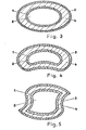
- Hollow threads that have a cross-sectional shape that differs from the circular shape, as shown in FIGS. 3 to 5, can also be used for pickup systems.
- the thread according to the invention can also be used according to the invention for piezoelectric sensors for mechanical loads.
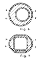
- e.g. B. the cross-sectional shape shown in FIGS. 6 and 7 is suitable.
- Corresponding threads according to the invention can, for example, be woven into woven or knitted fabrics as measuring probes.
- the thread according to the invention can also be used as a sensor in a sports fencing weapon in order to obtain the electrical impulses for the hit display.
- sensor switches can be produced with the thread according to the invention.
- the thread according to the invention is excellently suited as a hollow thread with precisely circular cross sections as a flexible waveguide for the transmission of the highest frequencies, since it can be produced by the spinning technology in such small transverse dimensions that the radius of the hollow cross section remains small compared to the wavelength even at the highest frequencies.
- the hollow fiber according to the invention can be produced without difficulty with a radius of the cavity cross section of 30 ILm.
- 1 to 7 show thread cross-sections which the thread according to the invention can have, for example.
- 1 denotes the inner electrically conductive layer, provided hollow threads are shown, the cavity is designated 2, while 3 is the outer electrically conductive layer.
- the intermediate layer of an electrically insulating synthetic polymer has been designated 4.
- FIG. 1 shows a multi-component thread of the core-sheath type with an electrically conductive core component and an electrically conductive outer layer extending over the entire circumference.
- Fig. 2 shows a hollow thread, the size ratios deliberately not drawn to scale because of the greater clarity in the dimensions, which has exactly circular cross-sections.
- FIG. 1 A hollow thread is shown with a circular cross section, the outer boundary and the inner boundary are eccentric to each other. This regularly results in different wall thicknesses, which lead to special radiation and frequency response effects in electroacoustic transducers.
- Fig. 7 shows a hollow fiber cross-sectional shape that differs from the circular shape and in which the wall thickness is not constant over the circumference.
Landscapes
- Engineering & Computer Science (AREA)
- Textile Engineering (AREA)
- Chemical & Material Sciences (AREA)
- Signal Processing (AREA)
- Mechanical Engineering (AREA)
- Acoustics & Sound (AREA)
- Physics & Mathematics (AREA)
- Chemical Kinetics & Catalysis (AREA)
- General Chemical & Material Sciences (AREA)
- Multicomponent Fibers (AREA)
- Laminated Bodies (AREA)
- Piezo-Electric Transducers For Audible Bands (AREA)
- Electrostatic, Electromagnetic, Magneto- Strictive, And Variable-Resistance Transducers (AREA)
Description
- Die Erfindung betrifft einen Faden gemäß dem ersten Teil des Anspruchs 1.
- Aus der DE-A-1 710 628 ist ein derartiger Faden bekannt. Er besteht aus mindestens zwei Komponenten, die sich im wesentlichen entlang der Fadenachse erstrecken und in einem beliebigen Querschnitt des Fadens mindestens zehn dünne Schichten bilden. Dabei kann eine der Komponenten eine Substanz zur Erhöhung der elektrischen Leitfähigkeit sein, um elektrostatische Aufladungen abzuleiten. Als Substan- . zen für die elektrisch leitfähigen Schichten werden organische Verbindungen vorgeschlagen, die zur Ableitung der statischen Elektrizität geeignet sind. Für andere Anwendungszwecke wie sie mit der vorliegenden Erfindung angestrebt werden, sind diese bekannten Fäden aber ungeeignet.
- Auch der aus der US-PS 4 045 949 bekannte elektrisch leitende textile Faden mit 2 bis 1000 elektrisch leitfähigen, längs der Fadenachse ausgerichteten Streifen und damit verbundenen nicht leitenden Streifen aus Polymermaterial dienen der Ableitung der statischen Elektrizität von textilen Synthesefäden. Auch dieser Faden ist für die angestrebten Anwendungszwecke ungeeignet.
- Es ist bekannt, daß ein Gebilde, welches aus zwei elektrisch leitenden Platten, die durch ein Dielektrikum voneinander isoliert sind, eine definierte elektrische Kapazität aufweist und somit einen Kondensator bildet. Gut bekannt sind Wickelkondensatoren aus Kunststoff-Folien mit Belägen aus Metallfolie, oder Metallbeläge, die unmittelbar auf die Kunststoff-Folien aufgedampft sind. Derartige Folien werden gewickelt und bilden anschließend den Kondensator.
- Es ist auch bekannt, daß piezoelektrische Kunststoff-Folien die mit leitenden Belägen versehen sind sich hervorragend für elektroakustische Wandler eignen, und sich inzwischen für Mikrofone, Tonabnehmer, Hochtonlautsprecher bewährt haben. Beschrieben sind derartige elektroakustische Wandler beispielsweise in der BE-A-858 882, den DE-A-2 623 930 und 2 742 133, sowie der US-A-4 064 375.
- Die Folien müssen sowohl für die Anwendung als Kondensatoren als auch zu elektroakustischen Wandlern sehr mühsam und sorgfältig verarbeitet und gewickelt werden. Für Miniaturbauteile lassen sich die Folien nur schwierig rationell vorbereiten und verarbeiten. Außerdem müssen trotz aller Sorgfalt in der Produktion, große Abweichungen von den Normdaten in Kauf genommen werden.
- Aufgabe der vorliegenden Erfindung war es, diese genannten Nachteile zu überwinden und Materialien zur Verfügung zu stellen, die die Anwendungsmöglichkeiten noch erweitern. Ausgehend von einem Faden, wie er aus der DE-A-1 210 628 bekannt war, dessen Querschnitt senkrecht zur Fadenlaufrichtung mindestens drei Schichten aufweist, von denen mindestens zwei Schichten elektrisch leitend sind und von denen wenigstens eine Schicht eine zwischen den leitenden Schichten liegende, aus einem elektrisch isolierenden synthetischen Polymeren bestehende Isolierschicht ist, wird die Aufgabe erfindungsgemäß gelöst durch einen solchen Faden, der dadurch gekennzeichnet ist, daß die Isolierschicht senkrecht zur Fadenlaufrichtung einen hohlförmigen Querschnitt aufweist, daß eine der elektrisch leitenden Schichten eine auf der Außenfläche der Isolierschicht angeordnete, sich über deren ganzen Umfang erstreckende äußere leitende Schicht darstellt und das wenigstens die äußere leitende Schicht eine galvanisch abgeschiedene Metallschicht ist.
- Kern-Mantel-Bikomponentenfäden sind bereits in großer Vielfalt zu verschiedenen Zwekken hergestellt worden. Unter anderem sind auch bereits Kern-Mantel-Bikomponentenfäden mit einem elektrisch leitenden Kern hergestellt worden, wie sie beispielsweise in der GB-A-816 965, der US-A-3 003 223 und der DE-A-2 337 103 beschrieben werden. Der erfindungsgemäße Faden kann nach analogen Spinnverfahren oder anderen Verfahren, wie sie in großer Zahl im Stande der Technik beschrieben sind, hergestellt werden. Wesentlich ist jedoch, daß dabei oder in einer nachgestalteten Verfahrensstufe, die elektrisch leitfähigen Schichten erzeugt werden. Beispielsweise können zur Haftungsvermittlung für galvanische Überzüge beim Spinnprozeß zusätzlich dünne Zwischenschichten aus Polymer-Metallpulver-Gemischen extrudiert werden, wobei dann entsprechende, bekannte Mehrkomponentendüsen mit mehreren konzentrischen Ringschlitzen verwendet werden, denen die unterschiedlichen Schmelzströme zugeführt werden. Geeignete Vorrichtungen beschreibt die NL-A-6 712 909.
- Insbesondere dann, wenn dem erfindungsgemäßen Faden piezoelektrische Eigenschaften durch eine Nachbehandlung des Polymeren vermittelt werden sollen, ist es sinnvoll, daß die Kernkomponente kompressibel ist. Eine geeignete Ausführungsform besteht darin, als Kernkomponente eine elektrisch leitende hochviskose Flüssigkeit mit darin dispergierten Metall-und/oder Ruß- und/oder Graphitteilchen einzusetzen. Geeignete hochviskose Flüssigkeiten sind beispielsweise Cis- und Trans-Polyacethylene mit relativ geringem Molekulargewicht, die gegebenenfalls einen geringen Anteil Jod oder Arsenpentachlorid enthalten.
- Eine besonders bevorzugte Ausführungsform der Erfindung besteht darin, daß der Faden ein im Fadenquerschnitt aus mindestens drei Schichten aufgebauter Hohlfaden ist. Die Herstellung der im Inneren des Hohlfadens liegenden elektrisch leitenden Schicht kann so erfolgen, daß beim Extrudieren des Hohlfadens eine Mehrkomponentenhohlfadendüse verwendet wird und mit dem isolierenden Polymeren gemeinsam eine Zwischenschicht aus einem Polymer-Metallpulver-Gemisch koextrudiert wird. In den Hohlraum wird durch ein durch die Spinndüsenöffnung durchgeführtes Rohr in einem ausreichenden Abstand von der Austrittsstelle des frisch gesponnenen Fadens eine Lösung zur chemischen Abscheidung von Kupfer oder Nickel in den Hohlraum des Fadens gespritzt, durch die während der Nachbehandlung des Fadens eine vollständige Bedeckung der Innenwandfläche mit dem Metall erfolgt.
- Falls es erforderlich ist, kann diese Metallschicht nach Aufteilung des Fadens in geeignete Abschnitte und Austausch der Hohlraumflüssigkeit durch ein galvanisches Bad mit einem weiteren Metallüberzug durch galvanische Abscheidung verstärkt werden.
- Diese Galvanische Abscheidung kann gleichzeitig mit der Abscheidung der elektrisch leitenden äußeren Schicht erfolgen. Zur Haftverbesserung ist es vorteilhaft, wenn auch außen eine dünne Außenschicht eines Polymer-Metallpulver-Gemisches koextrudiert wird.
- Der Faden gemäß der Erfindung wird nach den für die Herstellung von synthetischen Fäden bekannten Technologien hergestellt. Die Fadendurchmesser entsprechen auch den von dort bekannten Abmessungen von ca. 10 um bis zu etwa 3 mm. Vorzugsweise liegen die Fadendurchmesser jedoch zwischen 50 und 1000 um. Typische Fadendurchmesser sind 180 um, 250 µm und 450 µm. Bei Hohlfäden beträgt die Wandstärke im allgemeinen 1/8 bis 1/20 des Fadendurchmessers. Typisch sind hier Wandstärken von 10 bis 100 µm.
- Der erfindungsgemäße Faden muß aus mindestens drei Schichten aufgebaut sein, kann aber auch zusätzliche Schichten aufweisen, wo dieses zweckmäßig und sinnvoll erscheint. In vielen Fällen wird der Faden mit Zwischenschichten zur Erhöhung der Haftung der elektrisch leitenden Schichten hergestellt. Diese Zwischenschichten enthalten im allgemeinen Metallpulver zur Erhöhung der Leitfähigkeit der Zwischenschicht, die aber zu gering ist, als daß die Zwischenschicht bereits als Kontaktschicht gelten könnte. In vielen Fällen ist es sinnvoll, den Faden außen mit einer isolierenden Schutzschicht zu versehen, während die übrigen Schichten mit Ausnahme der Kontaktschichten im allgemeinen bei der Fadenbildung erzeugt werden, wird die Schutzschicht erst nach Fertigstellung des übrigen Fadens aufgebracht.
- Die elektrisch isolierende Schicht zwischen den Kontaktschichten kann selbst aus mehreren isolierenden Schichten, beispielsweise aus unterschiedlichen Polymeren bestehen. Durch eine solche Ausbildung des Erfindungsgegenstandes können Eigenschaften der Polymeren in stärkerem Maße miteinander kombiniert, beispielsweise gute Piezoelektrizität des einen Polymeren mit mechanischen Eigenschaften des anderen Polymeren, zur Wirkung kommen.
- Der erfindungsgemäße Faden läßt sich auf üblichen Textilmaschinen verarbeiten (Spulen, Zwirnen etc.). Gewebe, Gewirke und Stücke können beispielsweise zugleich dekorative Verkleidung und technisch funktionelles Teil, beispielsweise eine Schallwand bilden.
- Besondere Ausführungsformen der Erfindung ergeben sich dadurch, daß der Faden vom Kreisquerschnitt abweicht. Beispiele für solche, von der Kreisform abweichende Fadenquerschnitte, von Hohlfäden sind in den Fig. 3 bis 5 dargestellt.
- Als Polymere sind für den erfindungsgemäßen Faden alle Polymeren geeignet, die aus der Schmelze und/oder aus Lösungen zu Fäden verformbar sind und eine hohe Dielektrizitätskonstante aufweisen. Es können beispielsweise Polyamide, ein schließlich der aromatischen Polyamide, Polyester, insbesondere Polyalkylenterephthalate, Polycarbonate, Polyvinylidenfluorid, Polyurethane, Polyphosphazene als synthetisches Polymer für die isolierende Zwischenschicht eingesetzt werden.
- Vorteilhaft, insbesondere im Hinblick auf die Auslösung von piezoelektrischen Eigenschaften, soll das elektrisch isolierende synthetische Polymere mindestens teilweise kristallisierbar sein. Nicht nur im Hinblick auf die piezoelektrischen Eigenschaften soll das Polymere molekular orientierbar sein. Durch die molekulare Orientierung werden die mechanischen Eigenschaften des erfindungsgemäßen Fadens wesentlich verbessert.
- Es ist bekannt, daß die überwiegende Zahl der zuvor beispielhaft aufgezählten Polymeren, insbesondere, wenn sie zumindestens teilweise kristallisierbar sind, bei Einwirkung einer Gleichspannung bei erhöhter Temperatur bleibende piezoelektrische Eigenschaften erhalten. Ein auf das Polymere ausgeübter Druck erzeugt elektrische Impulse, die durch die Leitschichten aufgenommen und weitergeleitet werden. Legt man Wechselspannungen an die Leitschichten an, dann wird das Polymere in Schwingungen versetzt.
- Methoden, nach denen Polymeren piezoelektrische Eigenschaften vermittelt werden, sind bereits beschrieben worden und auch auf Polymerfolien in größerem Maßstab angewendet worden. Hier können beispielsweise die NL-A-7113160 und die DE-A-2 719 881 genannt werden.
- Der erfindungsgemäße Faden kann mit geeigneten Abmessungen als Kondensator eingesetzt werden, wenn jeweils die innere und die äußere elektrisch leitende Schicht mit einem Anschluß versehen werden.
- Die Kapazität des Kondensators ergibt sich aus den gewählten Abmessungen und läßt sich nach der Formel

- Bei einem Kern-Mantel-Faden mit einem elektrisch leitenden Kern kann dieser Kern mit einer genau bestimmten spezifischen Leitfähigkeit durch Mischung von Ruß und/oder Metallpulver mit geeigneten Polymeren hergestellt werden.
- Ein derartiger Kondensator weist dann an der inneren Kontaktstelle dadurch gleichzeitig einen definierten elektrischen Widerstand auf, so daß Kondensatoren entstehen, die sehr platzsparend gleich als RC-Glieder in elektronische Schaltungen eingebaut werden können.
- Der erfindungsgemäße Faden läßt sich ohne Einschränkung auf Textilmaschinen verarbeiten, woraus sich zahlreiche weitere vorteilhafte Möglichkeiten ergeben.
- Insbesondere für Bauteile mit kleiner Kapazität, mit besonders kleinen Abmessungen, wie sie für hohe und höchste Ansprüche erwünscht sind, läßt sich der erfindungsgemäße Faden hervorragend verwenden.
- Erfindungsgemäß läßt sich der Faden gemäß der Erfindung der piezoelektrische Eigenschaften aufweist, zu elektroakustischen Wandlersystemen verwenden.
- Flachmembranen haben sich hier bereits bewährt, bringen jedoch beim Einbau zahlreiche Schwierigkeiten mit sich. Vorteilhaft ist es, dazu erfindungsgemäße Hohlfäden einzusetzen, die sich zu Mikrofonen, Lautsprechern, Telefonkapseln und Kopfhöhrern mit gleichbleibenden und guten technischen Daten, wie beispielsweise Übertragungsbereich, Frequenzgang und Empfindlichkeit herstellen lassen. Wandlersysteme mit dem erfindungsgemäßen Faden weisen vor allem einen geringen Klirrfaktor auf und sind auch bei tieferen Hörfrequenzen einsetzbar. Für Tonabnehmersysteme sind vor allem auch Hohlfäden einsetzbar, die eine von der Kreisform abweichende Querschnittsform aufweisen, wie sie in den Fig. 3 bis 5 dargestellt sind.
- Der erfindungsgemäße Faden kann, wenn ihm durch Polarisation im Gleichspannungsfeld piezoelektrische Eigenschaften vermittelt wurden, erfindungsgemäß auch zu piezoelektrischen Sensoren auf mechanische Beanspruchungen verwendet werden. Hierzu ist z. B. die in Fig. 6 und 7 dargestellte Querschnittsform geeignet. Entsprechende erfindungsgemäße Fäden können beispielsweise in Gewebe oder Gewirke als Meßsonden eingewebt werden. Der erfindungsgemäße Faden kann auch in einer Sportfechtwaffe als Sensor eingesetzt werden, um die elektrischen Impulse für die Trefferanzeige zu gewinnen. Ferner lassen sich mit dem erfindungsgemäßen Faden Sensorschalter herstellen.
- Der erfindungsgemäße Faden ist als Hohlfaden mit genau kreisförmigen Querschnitten hervorragend als flexibler Hohlleiter für die Übertragung höchster Frequenzen geeignet, da er durch die Spinntechnik in so geringen Querabmessungen herstellbar ist, daß der Radius des Hohlrauniquerschnittes klein gegenüber der Wellenlänge selbst bei höchsten Frequenzen bleibt. Der erfindungsgemäße Hohlfaden läßt sich ohne Schwierigkeit mit einem Radius des Hohlraumquerschnittes von 30 ILm herstellen.
- Aus diesen geringen Abmessungen des Hohlraumquerschnittes ergibt sich auch die Verwendung des erfindungsgemäßen Fadens für Topfkreise im Bereich höchster Frequenzen (bis in den hohen Gigaherzbereich hinein).
- In den Fig. 1 bis 7 sind Fadenquerschnitte dargestellt, die beispielsweise der erfindungsgemäße Faden aufweisen kann.
- Mit 1 wird jeweils die innere elektrisch leitende Schicht bezeichnet, sofern Hohlfäden dargestellt sind, ist der Hohlraum mit 2 bezeichnet, während 3 die äußere elektrisch leitende Schicht ist. Die dazwischen liegende Schicht aus einem elektrisch isolierenden synthetischen Polymeren ist mit 4 bezeichnet worden.
- Im einzelnen zeigt die Fig. 1 einen Mehrkomponentenfaden vom Kern-Mantel-Typ mit einer elektrisch leitenden Kernkomponente und einer sich über den ganzen Umfang erstreckenden elektrisch leitenden äußeren Schicht.
- Fig. 2 zeigt einen Hohlfaden, wobei die Größenverhältnisse bewußt wegen der größeren Klarheit in den Abmessungen nicht maßstabsgerecht gezeichnet sind, der genau kreisförmige Querschnitte aufweist.
- In den Fig. 3 bis 5 sind Hohlfadenquerschnitte - ebenfalls nicht maßstabsgerecht - mit von der Kreisform abweichenden Querschnittsformen dargestellt.
- In Fig. ist ein Hohlfaden mit kreisförmigem Querschnitt dargestellt, wobei die äußere Begrenzung und die Innenbegrenzung zueinander exzentrisch sind. Daraus ergeben sich regelmäßig unterschiedliche Wandstärken, die bei elektroakustischen Wandlern zu besonderen Abstrahlungs- und Frequenzgangeinflüssen führen.
- Fig. 7 zeigt eine Hohlfadenquerschnittsform, die von der Kreisform abweicht und bei der die Wandstärke über den Umfang nicht konstant ist.
Claims (14)
Priority Applications (1)
| Application Number | Priority Date | Filing Date | Title |
|---|---|---|---|
| AT80100255T ATE3603T1 (de) | 1979-01-24 | 1980-01-21 | Faden mit leitschichten und dessen verwendung. |
Applications Claiming Priority (2)
| Application Number | Priority Date | Filing Date | Title |
|---|---|---|---|
| DE2902545A DE2902545C2 (de) | 1979-01-24 | 1979-01-24 | Faden mit Leitschichten |
| DE2902545 | 1979-01-24 |
Publications (2)
| Publication Number | Publication Date |
|---|---|
| EP0013952A1 EP0013952A1 (de) | 1980-08-06 |
| EP0013952B1 true EP0013952B1 (de) | 1983-05-25 |
Family
ID=6061238
Family Applications (1)
| Application Number | Title | Priority Date | Filing Date |
|---|---|---|---|
| EP80100255A Expired EP0013952B1 (de) | 1979-01-24 | 1980-01-21 | Faden mit Leitschichten und dessen Verwendung |
Country Status (5)
| Country | Link |
|---|---|
| US (1) | US4303733A (de) |
| EP (1) | EP0013952B1 (de) |
| JP (1) | JPS55123298A (de) |
| AT (1) | ATE3603T1 (de) |
| DE (1) | DE2902545C2 (de) |
Cited By (1)
| Publication number | Priority date | Publication date | Assignee | Title |
|---|---|---|---|---|
| DE102008003122A1 (de) * | 2008-01-02 | 2009-07-09 | Ofa Bamberg Gmbh | Faden zur Ermittlung der Zugspannung, insbesondere in einem medizinischen Gestrick oder Gewirk |
Families Citing this family (47)
| Publication number | Priority date | Publication date | Assignee | Title |
|---|---|---|---|---|
| FR2519503B1 (fr) * | 1981-12-31 | 1991-09-06 | Thomson Csf | Transducteurs piezoelectriques polymeres et procede de fabrication |
| ATE25898T1 (de) * | 1982-03-18 | 1987-03-15 | British Telecomm | Piezoelektrische und pyroelektrische folie. |
| GB2123602B (en) * | 1982-07-06 | 1987-02-25 | Raytheon Co | Piezo electric transducer and method of making same |
| US4487996A (en) * | 1982-12-02 | 1984-12-11 | Electric Power Research Institute, Inc. | Shielded electrical cable |
| US4629925A (en) * | 1983-11-22 | 1986-12-16 | Raychem Corporation | Piezoelectric coaxial cable |
| FR2559984B1 (fr) * | 1984-02-17 | 1987-01-16 | Thomson Csf | Microphone auriculaire de contact |
| US4609845A (en) * | 1984-07-06 | 1986-09-02 | Raychem Corporation | Stretched piezoelectric polymer coaxial cable |
| EP0187829B1 (de) * | 1984-07-06 | 1991-12-18 | Focas Limited | Piezoelektrisches koaxialkabel |
| CA1267216A (en) * | 1984-07-06 | 1990-03-27 | Pravin L. Soni | Piezoelectric device |
| GB2175771B (en) * | 1985-04-17 | 1989-01-11 | Geoquip Security Systems Ltd | Vibration sensitive transducer |
| US4634805A (en) * | 1985-05-02 | 1987-01-06 | Material Concepts, Inc. | Conductive cable or fabric |
| US5024872A (en) * | 1986-02-27 | 1991-06-18 | Raytheon Company | Sheets of stretched and polarized polymer materials and method of manufacturer |
| FR2596568B1 (fr) * | 1986-03-25 | 1989-10-27 | Thomson Csf | Cable piezoelectrique et procede de fabrication d'un cable |
| US4777338A (en) * | 1987-04-08 | 1988-10-11 | Cross James D | Perforation of synthetic plastic films |
| JPS6431481A (en) * | 1987-07-27 | 1989-02-01 | Idemitsu Petrochemical Co | Piezoelectric material |
| US4908740A (en) * | 1989-02-09 | 1990-03-13 | Hudgins Richard D | Integral composite structure with predetermined electrically conductive networks and method for producing same |
| DE4033091C1 (en) * | 1990-10-18 | 1992-03-12 | Messerschmitt-Boelkow-Blohm Gmbh, 8012 Ottobrunn, De | Controlling elastic characteristics of sensor - by embedding electrostrictive fibres in electroconductive matrix on non-conductive matrix e.g. of silicon carbide |
| DE4033089C1 (en) * | 1990-10-18 | 1992-03-12 | Messerschmitt-Boelkow-Blohm Gmbh, 8012 Ottobrunn, De | Torsion element for electrostrictive rod or band - uses electrostrictive fibres each with electrically conductive core and piezoelectric outer coating |
| US5090053A (en) * | 1991-01-03 | 1992-02-25 | Dalton Enterprises | Composite shock absorbing garment |
| EP0545707B1 (de) * | 1991-12-04 | 1997-09-17 | Canon Kabushiki Kaisha | Führungsglied und Gerät, das dieses verwendet |
| US5486820A (en) * | 1992-12-18 | 1996-01-23 | The Whitaker Corporation | Traffic sensor having piezoelectric sensors which distinguish lanes |
| US5371326A (en) * | 1993-08-31 | 1994-12-06 | Clearwaters-Dreager; Cindy | Non-toxic fabric conductors and method for making same |
| DE29613141U1 (de) * | 1996-07-29 | 1996-09-19 | Gattringer, Michael, 85640 Putzbrunn | Füllstandsgeber |
| US5904982A (en) * | 1997-01-10 | 1999-05-18 | Basf Corporation | Hollow bicomponent filaments and methods of making same |
| US6117802A (en) * | 1997-10-29 | 2000-09-12 | Alliedsignal Inc. | Electrically conductive shaped fibers |
| US6085061A (en) * | 1998-12-22 | 2000-07-04 | Xerox Corporation | Active electrostatic cleaning brush |
| GB2345795B (en) * | 1999-01-13 | 2003-05-21 | Marconi Applied Techn Ltd | Electron beam tube |
| DE19910012C1 (de) * | 1999-03-08 | 2001-01-18 | Ostthueringische Materialpruef | Verfahren zur Herstellung von Formkörpern |
| US6825418B1 (en) | 2000-05-16 | 2004-11-30 | Wpfy, Inc. | Indicia-coded electrical cable |
| FR2811431B1 (fr) * | 2000-07-07 | 2002-10-11 | Somfy | Dispositif de detection de mouvement et dispositif de securite pour store a bras |
| US6784370B1 (en) * | 2003-07-21 | 2004-08-31 | Ideal Industries, Inc. | Twist-on wire connector |
| EP1507040A1 (de) * | 2003-08-13 | 2005-02-16 | Heimbach GmbH & Co. | Textilerzeugnis mit einem integrierten Sensor zur Messung von Druck und Temperatur |
| DE102005055842A1 (de) * | 2005-11-23 | 2007-05-24 | Alpha-Fit Gmbh | Drucksensor |
| US8905108B2 (en) | 2007-06-04 | 2014-12-09 | Encore Wire Corporation | Method and apparatus for applying labels to cable |
| ATE504678T1 (de) * | 2007-06-07 | 2011-04-15 | Albany Int Corp | Leitfähiges monofilament und gewebe |
| US7954530B1 (en) | 2009-01-30 | 2011-06-07 | Encore Wire Corporation | Method and apparatus for applying labels to cable or conduit |
| US11319104B1 (en) | 2009-01-30 | 2022-05-03 | Encore Wire Corporation | System and apparatus for applying labels to cable or conduit |
| US8826960B1 (en) | 2009-06-15 | 2014-09-09 | Encore Wire Corporation | System and apparatus for applying labels to cable or conduit |
| USD632259S1 (en) | 2010-03-16 | 2011-02-08 | Leppert James B | Coaxial cable |
| DE102010019666A1 (de) * | 2010-04-28 | 2011-11-03 | Technische Universität Dresden | Aktorisches, sensorisches und/oder generatorisches Faserverbundbauteil und Verfahren zu seiner Herstellung |
| EP2441867A1 (de) * | 2010-10-18 | 2012-04-18 | Sefar Ag | Dehnungssensor und Verfahren zum Messen einer Dehnung eines Textils |
| CN102682873B (zh) * | 2012-04-11 | 2013-06-12 | 济南宝世达实业发展有限公司 | 新型空心导线及其制作方法 |
| FR2996563B1 (fr) * | 2012-10-08 | 2015-06-19 | Univ Haute Alsace | Procede de filage d'une fibre composite a base de polymere |
| DE102014103978A1 (de) * | 2014-03-24 | 2015-09-24 | Ditf Deutsche Institute Für Textil- Und Faserforschung Stuttgart | Sensorgarn |
| US9974170B1 (en) | 2015-05-19 | 2018-05-15 | Apple Inc. | Conductive strands for fabric-based items |
| FR3067363B1 (fr) * | 2017-06-09 | 2019-06-28 | Arkema France | Fibre multicouche de polymeres fluores |
| CN108893818B (zh) * | 2018-08-23 | 2020-10-02 | 中原工学院 | 一种柔性导电纱线及其制备方法 |
Family Cites Families (22)
| Publication number | Priority date | Publication date | Assignee | Title |
|---|---|---|---|---|
| GB816965A (en) * | 1956-10-24 | 1959-07-22 | Plessey Co Ltd | Improvements in or relating to electrically resistive or conductive filaments |
| DE756697C (de) * | 1940-11-24 | 1952-12-22 | Zeiss Ikon Ag | Piezoelektrisches Druckelement |
| US3003223A (en) * | 1957-03-25 | 1961-10-10 | Du Pont | Metal core composite filaments |
| NL221471A (de) * | 1957-10-09 | |||
| US3397085A (en) * | 1962-12-27 | 1968-08-13 | Union Carbide Corp | Thin film capacitors |
| DE1490867A1 (de) * | 1963-11-08 | 1969-08-28 | Inducal Berlin Hermann Schlimm | Hochspannungsspezialkabel fuer elektrostatische Anlagen |
| CH486570A (de) * | 1966-09-21 | 1970-02-28 | Inventa Ag | Vorrichtung zur Herstellung von aus mindestens zwei verschiedenen Polymeren bestehenden Verbundfäden |
| CH503353A (fr) * | 1969-05-14 | 1971-02-15 | Aerocoat Sa | Dispositif conducteur destiné à relier une source de courant continu à haute tension à un récepteur |
| JPS5040720B1 (de) * | 1970-09-26 | 1975-12-26 | ||
| US3931446A (en) * | 1970-09-26 | 1976-01-06 | Kureha Kagaku Kogyo Kabushiki Kaisha | Process for producing polymeric piezoelectric elements and the article formed thereby |
| US3803453A (en) * | 1972-07-21 | 1974-04-09 | Du Pont | Synthetic filament having antistatic properties |
| AT336765B (de) * | 1972-11-06 | 1977-05-25 | Lurex Bv | Mehrkomponentenfaden |
| GB1520118A (en) * | 1975-08-11 | 1978-08-02 | Rank Organisation Ltd | Transducers |
| US4045949A (en) * | 1976-01-02 | 1977-09-06 | Dow Badische Company | Integral, electrically-conductive textile filament |
| US4089034A (en) * | 1976-04-30 | 1978-05-09 | Minnesota Mining And Manufacturing Company | Machine and method for poling films of pyroelectric and piezoelectric material |
| DE2623930A1 (de) * | 1976-05-28 | 1977-12-15 | Sennheiser Electronic | Drucktasteneinheit nach dem piezoelektrischen wandlungsprinzip |
| GB1593271A (en) * | 1976-09-21 | 1981-07-15 | Standard Telephones Cables Ltd | Electro-acoustic transducers |
| MX145379A (es) | 1976-09-24 | 1982-01-29 | Pennwalt Corp | Metodo mejorado para polarizar una pila de capas multiples de peliculas formadoras de elementos piezoelectricos |
| US4139936A (en) * | 1977-07-05 | 1979-02-20 | Hughes Aircraft Company | Method of making hermetic coaxial cable |
| AU503665B1 (en) * | 1977-08-08 | 1979-09-13 | Kanebo Limited | Conductive composite filaments |
| US4188651A (en) * | 1978-03-27 | 1980-02-12 | Sprague Electric Company | Ceramic capacitor with surface electrodes |
| JPS551337A (en) * | 1978-06-15 | 1980-01-08 | Toray Ind Inc | Electrically conducitive synthetic fiber and its production |
-
1979
- 1979-01-24 DE DE2902545A patent/DE2902545C2/de not_active Expired
-
1980
- 1980-01-21 US US06/113,667 patent/US4303733A/en not_active Expired - Lifetime
- 1980-01-21 AT AT80100255T patent/ATE3603T1/de not_active IP Right Cessation
- 1980-01-21 EP EP80100255A patent/EP0013952B1/de not_active Expired
- 1980-01-24 JP JP638280A patent/JPS55123298A/ja active Pending
Cited By (1)
| Publication number | Priority date | Publication date | Assignee | Title |
|---|---|---|---|---|
| DE102008003122A1 (de) * | 2008-01-02 | 2009-07-09 | Ofa Bamberg Gmbh | Faden zur Ermittlung der Zugspannung, insbesondere in einem medizinischen Gestrick oder Gewirk |
Also Published As
| Publication number | Publication date |
|---|---|
| DE2902545A1 (de) | 1980-09-18 |
| EP0013952A1 (de) | 1980-08-06 |
| DE2902545C2 (de) | 1985-04-04 |
| US4303733A (en) | 1981-12-01 |
| ATE3603T1 (de) | 1983-06-15 |
| JPS55123298A (en) | 1980-09-22 |
Similar Documents
| Publication | Publication Date | Title |
|---|---|---|
| DE2902545C2 (de) | Faden mit Leitschichten | |
| DE69704027T2 (de) | Elektrisch leitfähiges heterofilament | |
| DE1660182C3 (de) | Verfahren zur Herstellung von Kern-Hülle Verbundfäden | |
| DE69207775T2 (de) | Ein massenanschliessbares kabel | |
| DE3033162C2 (de) | Polymerelektret und Verfahren zu seiner Herstellung | |
| EP0029119B1 (de) | Verfahren zu Herstellung einer rauhen Elektroisolierfolie aus Polypropylen | |
| DE2329532C3 (de) | Mehrschichtiges flexibles Isolierband oder -blatt | |
| DE112017004598B4 (de) | Lautsprechermembran, Verfahren zu deren Herstellung und diese nutzender Lautsprecher | |
| EP2159857A1 (de) | Elektromechanischer Wandler | |
| DE2944506A1 (de) | Piezoelektrischer wandler fuer elektrische saiteninstrumente und diesen enthaltende tonabnehmer | |
| DE2618623C2 (de) | Mikroporöser Separator | |
| EP1060480A1 (de) | Durchführung für eine hohe elektrische spannung | |
| DE69406271T2 (de) | Piezoelektrisches bauelement und verfahren zu seiner herstellung | |
| DE4420328C2 (de) | Kabelmantel | |
| DE1802327C3 (de) | Elektrischer Kondensator | |
| DE2350913C3 (de) | Elektrisches Isoliermaterial | |
| DE3036931C2 (de) | ||
| DE2819377A1 (de) | Leitender kunststoff | |
| DE19531065A1 (de) | Nachrichtenkabel mit mindestens einem elektrischen Übertragungselement sowie Verfahren zur Herstellung | |
| DE1004252B (de) | Isolation aus Polyaethylen-Terephthalat-Folienmaterial fuer elektrische Vorrichtungen | |
| DE2850713A1 (de) | Antistatisches fadengebilde | |
| DE2601494A1 (de) | Verfahren zur herstellung einer funkantenne | |
| DE102012103301A1 (de) | Mittels Schmelzspinnverfahren hergestellte Faser | |
| DE3308300A1 (de) | Hochflexible miniaturkoaxialleitung | |
| DE102018216017A1 (de) | Verfahren zur Herstellung eines Stators, Stator und Elektromaschine |
Legal Events
| Date | Code | Title | Description |
|---|---|---|---|
| PUAI | Public reference made under article 153(3) epc to a published international application that has entered the european phase |
Free format text: ORIGINAL CODE: 0009012 |
|
| AK | Designated contracting states |
Designated state(s): AT CH FR GB IT NL |
|
| 17P | Request for examination filed |
Effective date: 19801011 |
|
| ITF | It: translation for a ep patent filed | ||
| GRAA | (expected) grant |
Free format text: ORIGINAL CODE: 0009210 |
|
| AK | Designated contracting states |
Designated state(s): AT CH FR GB IT NL |
|
| REF | Corresponds to: |
Ref document number: 3603 Country of ref document: AT Date of ref document: 19830615 Kind code of ref document: T |
|
| ET | Fr: translation filed | ||
| PGFP | Annual fee paid to national office [announced via postgrant information from national office to epo] |
Ref country code: CH Payment date: 19840104 Year of fee payment: 5 |
|
| PLBE | No opposition filed within time limit |
Free format text: ORIGINAL CODE: 0009261 |
|
| STAA | Information on the status of an ep patent application or granted ep patent |
Free format text: STATUS: NO OPPOSITION FILED WITHIN TIME LIMIT |
|
| 26N | No opposition filed | ||
| PGFP | Annual fee paid to national office [announced via postgrant information from national office to epo] |
Ref country code: FR Payment date: 19841218 Year of fee payment: 6 |
|
| PGFP | Annual fee paid to national office [announced via postgrant information from national office to epo] |
Ref country code: AT Payment date: 19851219 Year of fee payment: 7 |
|
| PGFP | Annual fee paid to national office [announced via postgrant information from national office to epo] |
Ref country code: NL Payment date: 19860131 Year of fee payment: 7 |
|
| PG25 | Lapsed in a contracting state [announced via postgrant information from national office to epo] |
Ref country code: AT Effective date: 19870121 |
|
| PG25 | Lapsed in a contracting state [announced via postgrant information from national office to epo] |
Ref country code: CH Effective date: 19870131 |
|
| PG25 | Lapsed in a contracting state [announced via postgrant information from national office to epo] |
Ref country code: NL Effective date: 19870801 |
|
| GBPC | Gb: european patent ceased through non-payment of renewal fee | ||
| NLV4 | Nl: lapsed or anulled due to non-payment of the annual fee | ||
| PG25 | Lapsed in a contracting state [announced via postgrant information from national office to epo] |
Ref country code: FR Free format text: LAPSE BECAUSE OF NON-PAYMENT OF DUE FEES Effective date: 19870930 |
|
| REG | Reference to a national code |
Ref country code: CH Ref legal event code: PL |
|
| REG | Reference to a national code |
Ref country code: FR Ref legal event code: ST |
|
| PG25 | Lapsed in a contracting state [announced via postgrant information from national office to epo] |
Ref country code: GB Effective date: 19881118 |