EP0013326A2 - Système de servo-positionnement à échantillonnage de données et son application dans une pile de disques à secteurs de servocommande - Google Patents
Système de servo-positionnement à échantillonnage de données et son application dans une pile de disques à secteurs de servocommande Download PDFInfo
- Publication number
- EP0013326A2 EP0013326A2 EP79104718A EP79104718A EP0013326A2 EP 0013326 A2 EP0013326 A2 EP 0013326A2 EP 79104718 A EP79104718 A EP 79104718A EP 79104718 A EP79104718 A EP 79104718A EP 0013326 A2 EP0013326 A2 EP 0013326A2
- Authority
- EP
- European Patent Office
- Prior art keywords
- signal
- model
- actuator
- stage
- velocity
- Prior art date
- Legal status (The legal status is an assumption and is not a legal conclusion. Google has not performed a legal analysis and makes no representation as to the accuracy of the status listed.)
- Granted
Links
Images


Classifications
-
- G—PHYSICS
- G05—CONTROLLING; REGULATING
- G05B—CONTROL OR REGULATING SYSTEMS IN GENERAL; FUNCTIONAL ELEMENTS OF SUCH SYSTEMS; MONITORING OR TESTING ARRANGEMENTS FOR SUCH SYSTEMS OR ELEMENTS
- G05B19/00—Programme-control systems
- G05B19/02—Programme-control systems electric
- G05B19/18—Numerical control [NC], i.e. automatically operating machines, in particular machine tools, e.g. in a manufacturing environment, so as to execute positioning, movement or co-ordinated operations by means of programme data in numerical form
- G05B19/19—Numerical control [NC], i.e. automatically operating machines, in particular machine tools, e.g. in a manufacturing environment, so as to execute positioning, movement or co-ordinated operations by means of programme data in numerical form characterised by positioning or contouring control systems, e.g. to control position from one programmed point to another or to control movement along a programmed continuous path
- G05B19/21—Numerical control [NC], i.e. automatically operating machines, in particular machine tools, e.g. in a manufacturing environment, so as to execute positioning, movement or co-ordinated operations by means of programme data in numerical form characterised by positioning or contouring control systems, e.g. to control position from one programmed point to another or to control movement along a programmed continuous path using an incremental digital measuring device
- G05B19/23—Numerical control [NC], i.e. automatically operating machines, in particular machine tools, e.g. in a manufacturing environment, so as to execute positioning, movement or co-ordinated operations by means of programme data in numerical form characterised by positioning or contouring control systems, e.g. to control position from one programmed point to another or to control movement along a programmed continuous path using an incremental digital measuring device for point-to-point control
- G05B19/231—Numerical control [NC], i.e. automatically operating machines, in particular machine tools, e.g. in a manufacturing environment, so as to execute positioning, movement or co-ordinated operations by means of programme data in numerical form characterised by positioning or contouring control systems, e.g. to control position from one programmed point to another or to control movement along a programmed continuous path using an incremental digital measuring device for point-to-point control the positional error is used to control continuously the servomotor according to its magnitude
- G05B19/232—Numerical control [NC], i.e. automatically operating machines, in particular machine tools, e.g. in a manufacturing environment, so as to execute positioning, movement or co-ordinated operations by means of programme data in numerical form characterised by positioning or contouring control systems, e.g. to control position from one programmed point to another or to control movement along a programmed continuous path using an incremental digital measuring device for point-to-point control the positional error is used to control continuously the servomotor according to its magnitude with speed feedback only
-
- G—PHYSICS
- G11—INFORMATION STORAGE
- G11B—INFORMATION STORAGE BASED ON RELATIVE MOVEMENT BETWEEN RECORD CARRIER AND TRANSDUCER
- G11B5/00—Recording by magnetisation or demagnetisation of a record carrier; Reproducing by magnetic means; Record carriers therefor
- G11B5/48—Disposition or mounting of heads or head supports relative to record carriers ; arrangements of heads, e.g. for scanning the record carrier to increase the relative speed
- G11B5/54—Disposition or mounting of heads or head supports relative to record carriers ; arrangements of heads, e.g. for scanning the record carrier to increase the relative speed with provision for moving the head into or out of its operative position or across tracks
- G11B5/55—Track change, selection or acquisition by displacement of the head
- G11B5/5521—Track change, selection or acquisition by displacement of the head across disk tracks
- G11B5/5526—Control therefor; circuits, track configurations or relative disposition of servo-information transducers and servo-information tracks for control thereof
- G11B5/553—Details
- G11B5/5547—"Seek" control and circuits therefor
-
- G—PHYSICS
- G05—CONTROLLING; REGULATING
- G05B—CONTROL OR REGULATING SYSTEMS IN GENERAL; FUNCTIONAL ELEMENTS OF SUCH SYSTEMS; MONITORING OR TESTING ARRANGEMENTS FOR SUCH SYSTEMS OR ELEMENTS
- G05B2219/00—Program-control systems
- G05B2219/30—Nc systems
- G05B2219/41—Servomotor, servo controller till figures
- G05B2219/41434—Feedforward FFW
-
- G—PHYSICS
- G05—CONTROLLING; REGULATING
- G05B—CONTROL OR REGULATING SYSTEMS IN GENERAL; FUNCTIONAL ELEMENTS OF SUCH SYSTEMS; MONITORING OR TESTING ARRANGEMENTS FOR SUCH SYSTEMS OR ELEMENTS
- G05B2219/00—Program-control systems
- G05B2219/30—Nc systems
- G05B2219/42—Servomotor, servo controller kind till VSS
- G05B2219/42155—Model
-
- G—PHYSICS
- G05—CONTROLLING; REGULATING
- G05B—CONTROL OR REGULATING SYSTEMS IN GENERAL; FUNCTIONAL ELEMENTS OF SUCH SYSTEMS; MONITORING OR TESTING ARRANGEMENTS FOR SUCH SYSTEMS OR ELEMENTS
- G05B2219/00—Program-control systems
- G05B2219/30—Nc systems
- G05B2219/42—Servomotor, servo controller kind till VSS
- G05B2219/42171—Velocity profile, variable gain, multiplication factors, rom ram
-
- G—PHYSICS
- G05—CONTROLLING; REGULATING
- G05B—CONTROL OR REGULATING SYSTEMS IN GENERAL; FUNCTIONAL ELEMENTS OF SUCH SYSTEMS; MONITORING OR TESTING ARRANGEMENTS FOR SUCH SYSTEMS OR ELEMENTS
- G05B2219/00—Program-control systems
- G05B2219/30—Nc systems
- G05B2219/42—Servomotor, servo controller kind till VSS
- G05B2219/42256—Sampling the signal
-
- G—PHYSICS
- G05—CONTROLLING; REGULATING
- G05B—CONTROL OR REGULATING SYSTEMS IN GENERAL; FUNCTIONAL ELEMENTS OF SUCH SYSTEMS; MONITORING OR TESTING ARRANGEMENTS FOR SUCH SYSTEMS OR ELEMENTS
- G05B2219/00—Program-control systems
- G05B2219/30—Nc systems
- G05B2219/42—Servomotor, servo controller kind till VSS
- G05B2219/42318—Using two, more, redundant measurements or scales to detect bad function
Definitions
- the present invention relates to servo positioning systems in which only sampled position data is available for feedback control.
- a typical positioning application to which the present invention can be applied is the movement of a magnetic head (transducer) between information bearing concentric tracks in a magnetic disk file of the so called "sector-servo" type.
- a magnetic head transducer
- servo position reference information is recorded in a plurality of spaced sectors interleaved between larger sectors on which the data is recorded.
- the time taken to move a head between tracks in a disk file is known as the "access" time and is one of the most important performance characteristics of a file.
- access time is one of the most important performance characteristics of a file.
- To minimise the access time for a file of given mechanical configuration and actuator performance requires an access motion control system which will control the velocity of the head in time-optimal fashion and which will bring the head accurately to rest on the desired track.
- the access motion is, therefore, necessarily of wide and width and the access control system is subject to the stability and error constraints of such systems.
- these wide band requirements have necessitated the use of a continuous position reference source such as a separate servo disk.
- near time-optimal access motion has been accomplished by means of a derived continuous distance-to-go signal acting on a reference velocity curve generator which, via a high gain forces the actual velocity of the head to follow a optimal reference velocity profile from the curve generator.
- the motion of the head during an access does not approach time optimal motion since it is at constant velocity over all but a few tracks.
- the constant velocity is low as the head only traverses one track per two sector periods and must be synchronized with the sector frequency. Furthermore; only in a low velocity system is it possible to effect the final deceleration under open loop conditions without significant final position error.
- the Oswald application is basically concerned with access control systems for use with files having continuous servo position information. It proposes that a combination of feed- forward and feedback control can enable high performance accesses even with low bandwidth fed back position information.
- a feedforward signal which is a prediction of required drive current in a nominal system, is applied to the head actuator to cause it to execute approximately a high performance (high bandwidth) access.
- low bandwidth head position or velocity information is fed back and compared with a stored velocity profile to correct small deviations between the nominal and actual systems.
- transducer incremental position signals are employed as the fed back quantity.
- the error signal is fed back to the model system but is also applied to control the physical system.
- the model velocity and position outputs are reset at sampling times to the values of the sampled velocity and position in the physical system.
- the servo sectors described in the Kurzweil application include track addresses as well as track following position information and the model and physical position signals are absolute (relative to the target address) rather than incremental (relative to the nearest track centre).
- a sampled data servo positioning system for moving a member between a current and a target position comprising: an actuator responsive to applied drive signals to move such a member; a position transducer movable with or part of the member for producing signals in response to motion thereof; position signal generating means responsive to the position transducer signals to produce at least one incremental position signal representative of the position of the member at sampling times; a model responsive to an input signal to produce at least one continually available model incremental position signal; profile signal generating means for generating a profile signal, corresponding to a predetermined velocity profile, as an input signal for the model; phase comparing means for comparing and indicating the phase difference between the sampled and model position signals at the sampling times; actuator feedforward signal genarating means for generating a feedforward control signal for the actuator corresponding to the predetermined velocity profile, and stage indicating means for indicating various stages of the motion in accordance with predetermined conditions; the system being characterized by switching means responsive to the stage indicating means to switch the system between first and
- the system according to the invention closely resembles that proposed by Oswald.
- an improvement in access time is offered by providing a first operational configuration in which the actuator is operated at maximum power under effectively open loop conditions.
- the model track the actuator system in the first operational configuration.
- the model incremental position signal remains continuous representative of the position of the transducer within acceptable limits of phase error and may be used for track counting without the need for stored addresses.
- the switching means is responsive to a first stage indication to switch the system into its first operational configuration with the acceleration saturation control signal applied to the actuator and is responsive to a second stage indication to maintain the system in its first operational configuration but with the maximum deceleration saturation control signal applied to the actuator.
- This feature enables the model signal to track the actuator and remain representative of actual position during current switching. If the model were driven from the stored profile signal as soon as the acceleration stage was over there would be no guarantee that the actual head velocity would follow that of the profile exactly and the model would be running disconnected from the file. An incremental position signal is only linear over 180° and phase errors greater than this cannot be tolerated without losing track of head position where a count of model position signal increments is maintained as the primary indication of absolute position. To change the current in this way is also faster.
- the switching means is responsive to a penultimate stage indication to switch the system into its first operational configuration with the maximum deceleration saturation control signal applied to the actuator and responsive to an ultimate stage indication to switch the system into its second operational configuration.
- stage indicating means is responsive to equality of a signal representative of the actuator current and the actuator feedforward signal to change from the penultimate to the ultimate stage.
- Yet another preferred feature of the invention is a system in which the motion includes a constant velocity stage corresponding to movement at a maximum permitted velocity, the switching means being responsive to a constant velocity stage indication to switch the system into its second operational configuration.
- a preferred feature of the model in systems according to the invention is that it comprises both a velocity model and a position model which produces the model incremental position signal.
- the actuator performance signal is preferably representative of actuator current and is applied to the velocity model which integrates it to produce a model velocity signal for application to the position model in the first operational configuration.
- the profile signal is preferably a velocity profile signal which is applied directly to the position model.
- Systems employing such a velocity profile signal preferably include as part of the profile signal generating means, a store from which the velocity profile signal is read out as a function of the position of the member, and normalising means for normalising the velocity profile to the value of the model velocity output when the system is switched from its first to its second configuration.
- the position model comprises a voltage controlled oscillator to which either the model velocity or the velocity profile signal is applied, a counter for counting the oscillator output pulses, means for reversing the direction of counting in response to the counter reaching either a maximum or a minimum count, and a digital to analog converter for converging the count to an analog model incremental position signal.
- the actuator feed- forward signal generating means includes a store from which the actuator feedforward control signal is read out as a function of the position of the member, the feedforward control signal being zero at greater than a predetermined distance from the target position, and being of substantially trapezoidal form between the predetermined distance and the target position so as to include an initial portion of gradually diminishing amplitude and a terminal portion of steeply falling amplitude which falls to zero at the target position.
- the invention is applicable to any sampled data servo positioning system, it is particularly applicable to a sector servo disk file in which the position transducer is a transducer for reading information from the disk file and the position signal generating means is responsive to signals read by the transducer from the servo sectors of the disk file.
- a sampled data servo positioning system is incorporated in a disk file of the sector servo type, where it is employed to control the movement of read/write transducers between tracks, it is desirable firstly to describe those features of the file relating to the sector servo information.
- Block 10 represents a circumferential band of information bearing tracks, drawn rectilinearly for convenience.
- Block 10 includes, in particular, a portion of the band of tracks which lies within a sector of servo position information.
- This servo sector is one of a number of such sectors disposed at equal angles about the disk axis and which extend from the inner diameter to the outer diameter of the usable recording area. Data is recorded in areas 1 along equally spaced concentric tracks between these servo sectors.
- the start of a servo sector is indicated by a mark field 2 of magnetic transitions, in radial alignment on every track, which is distinguishable from the permitted patterns of recorded data. Following the mark field is a gain. fiels 3, also of radially aligned magnetic transitions, which is employed for automatic gain control.
- a normal (N) servo field 4 contains a checkerpoard pattern of magnetisation in which transitions are aligned radially but are of opposite sense in alternate tracks. The tracks of the normal field are arranged so that the boundary between them lies on the centre line of the data tracks. This information is employen to provide an indication of the position of a read/write head 5 relative to the nearest track centre and to detect the "on-track" condition,
- quadrature (Q) field 6 containing an identical checkerboard pattern to the normal field but offset from it radially by half a track width so that the quadrature pattern tracks are aligned with the data tracks.
- the quadrature field is employed to provide additional information on the head pesition.
- the quadrature field terminates the servo sector and is followed by sector identifying information 7 and the next sector of data.
- Figure 2 shows a circuit for generating normal and quadrature head position signals by demodulation of the signal read by head 5 from the rotating disk.
- the signal from head 5 as it passes over the block 10 of information is shown as waveform 8 in Figure 1.
- the signal is amplified n a variable gain amplifier 30 and converted to proportional currents by amplifiers 31 and 31' in parallel channels. The outputs of these amplifiers are applied to demodulator switch circuits 32 and 32' respectively.
- the switch circuits are controlled by sample clocking signals generated by a sample logic circuit 40.
- a sample clock signal for demodulating the head signals 11 from the N region 4 is shown in waveform 16.
- a sample clock signal for demodulating the head signals from the Q region 6 is shown in waveform 15.
- the demodulation operation involves the rectification of the head signal from the Q region by inverting alternate peaks to produce the rectified signal 17. This is achieved by switching the arm of switch 32' alternately between contacts 33' and 34' in response to the level of signal 15. The signal is switched either directly to integrating capacitor 35' via contact 33' or to a current mirror 36' which effectively inverts the current to capacitor 35'.
- the rectified signal 17 is integrated by capacitor 35' and amplified by amplifier 37' as shown by output signal 18 whose peak value is the demodulated quadrature position signal Qs.
- Contact 38' of the demodulator switch is an "off" position and subsidiary switch 39' for connecting capacitor 35' to ground is a reset switch.
- the Qs position error signal illustrated in Figure 1 corresponds to the situation where head 5 is exactly aligned with the data tracks 1 and quadrature tracks 6 and is centred over a boundary of normal tracks 4. This position is referred to as the "on-track" position.
- the head signal from the N field 4 is demodulated in exactly the same manner as the Q field signal by correspondingly numbered (unprimed) circuitry. Since the head 5 is located over the boundary between two tracks it will receive equal and opposite signal contributions from the transitions on these tracks and produce a signal 11 whose average value is zero. Lack of precise alignment in transitions on adjacent tracks results in noise which is removed by integrating capacitor 35.
- the sample clock signals from sample logic 40 are generated in response to the detection of the mark pattern 12 at the beginning of a servo sector by mark detection circuit 41.
- this circuit is the same as a conventional address mark detection circuit employed in the data channel of a disk file to identify the start of sectors of data or index points.
- the principle is to detect a special transition pattern which breaks the rules for encoding data so that the pattern cannot be confused with data.
- the mark pattern produces a sequence of evenly spaced peaks one of which, at 13, is missing. The frequency of the peaks is different from the data frequency.
- the mark detector employs a zero crossing detector and a peak detector to set and reset a latch. Timing windows generated by associated counter circuitry allow the time of occurrence of the zero crossing to be checked for correspondence with the mark pattern. If the zero crossings occur as expected a "mark found" signal 19 is produced.
- This mark found signal is applied to the sample logic 40 and also to a phase locked oscillator 42 to synchronise it with the occurrence of the sectors.
- the PLO 42 produces an output which is a multiple of the sector frequency and is applied to a counter 43 to produce submultiples of the PLO output for the sample logic 40.
- the sample logic is responsive to the outputs of the PLO counter and to the "mark found" signal to produce sample clocking signals for controlling the servo position sampling operation and other aspects of the head positioning system to be described below.
- sample clocking signals are the signals 15 and 16 for alternating the switches 32 and 32' between positions 33, 33' and 34, 34' to demodulate the signals from the N and Q fields.
- Another sample clock signal (not shown) derived directly from the mark found signal causes the arm of switch 32 to be initially closed on contact 21 for the duration of the gain field 3.
- the head signal 14 from the gain field is full wave rectified in a rectifier 22 to produce the signal 20 shown in Figure 1.
- This signal is applied to a current source 23 which applies a charging input to a capacitor 24.
- the charging input is offset by a discharging input applied by a further current source 25 in response to a track reference current applied at a terminal 26.
- the track reference current represents the desired off track gain in volts/trac k for the N and Q position samples. If there is a net current to capacitor 24 the resultant voltage across the capacitor at the end of the gain field is amplified in amplifier 28 and is used to control the gain of VGA 30. In this way the positio samples Ns and Qs are normalised in terms of off-track gain by the operation of the gain control circuitry.
- the position samples Ns and Qs are employed in both the track following and access motion control aspects of head positioning.
- the signal Ns is nulled in a closed feedback loop to cause the head 5 to follow a data track. This aspect of position control is not relevant to the invention and no description of the track following system is considered necessary.
- Both the samples Ns and Qs are employed in the access motion (or seek) control system to be described below.
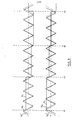
- Figure 3 shows, by way of example, how these position samples vary with motion of the head 5 across the tracks. A constant velocity of motion is assumed so that the basic variation of offtrack position with time is a regular triangular function. The actual variation of head position with time is illustrated by the dotted lines Ns' and Qs'.
- the actual head position samples Ns and Qs, generated by the circuit of Figure 2 are shown by continuous lines.
- the levels of Ns and Qs remain constant between servo sectors and are reset to new values at sampling times. Three such resettings are shown though their location is illustrative only. It has been assumed that the head 5 is crossing several tracks between samples which is the case only at the higher velocity portions of the seek motion. It will be noted that there is no relationship between the sampling points and the position of the head relative to a track.
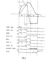
- Waveforms (a) of Figures 4 and 5 illustrate the variation of velocity with time for a short and a long seek respectively. Also shown are three other functions, namely the head actuator coil current (waveform b), the feedforward current function (waveform c), and the velocity profile (waveform d) all of which will be discussed below.
- the motion is divided into distinct stages Sl to S6 in Figure 5 and into corresponding stages Sl, S2/4, S5 and S6 in Figure 4.
- Stage S2/4 corresponds to the combination of stages S2 and S4 in Figure 5, omitting stage S-3. Subsequent references to stage S2 or S4 should be taken also to refer to the corresponding portion of S2/4, these stages will be related below to particular operational configurations of the circuitry of Figure 6.
- the head is accelerated from rest during stage S1 until, during stage S2/4, it reaches a peak velocity at about the mid-point of the distance to be travelled.
- the head is decelerated from the peak velocity during the remainder of stage S2/4 and throughout stage 5 until it comes to rest on the target track whereupon the track following stage S6, which forms no part of the present invention, commences.
- the head is accelerated during stages Sl and S2 until it reaches a maximum permitted velocity.
- the head is maintained at the maximum velocity during stage 3 and decelerated to rest during stages 4 and 5.
- the maximum velocity limitation is introduced since, in a practical system, a point,of diminishing returns is reached beyond which access time cannot be significantly improved by permitting the actuator to attempt to further accelerate the head.
- the access motion control system is illustrated in Figures 6 and 7. It is responsive to an initial seek command to move the head to a specified target track in the shortest time possible, consistent with the physical constraints on the system. In order to achieve minimum access times it is desirable to use maximum actuator power wherever possible.
- the system of Figures 6 and 7 has a first operational configuration, referred to as mode A, in which maximum power is applied. The system is in mode A during stages Sl, S2 and S4 of the motion.
- the system of figutes d and 7 has a second operational configuration, referred to as mode B, in which such tight control of head motion is effected.
- the system is in mode B during stage S5 of the motion.
- Mode B is also employed to control the system during tne constant velocity stage S3 of a long seek.
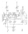
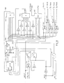
- Figure 6 shows the essential components of the preferred access motion control system according to the invention while Figure 7 shows circuitry for producing various control logic signals for application to the system of Figure 6.
- these signals comprise a signal A indicating mode A (waveforms (j)), a signal B (not shown) indicating mode B being the inverse of signal A, two signals ACCEL and DECEL (waveforms (g) and (i) respectively), and a signal RESET (waveform (m)).
- the other input signals to the system of Figure 6 are an IN/OUT signal giving the direction of motion, a relative track address which is a digital representation of the current displacement in tracks, of the head from its target position, and the sampled analog position error signals Ns and Qs of Figure 3.
- the system of Figure 6 develops a drive signal for a head actuator 50 of the moving coil type in driver amplifier 51 which causes the actuator to drive the head in the manner illustrated in Figures 4 and 5.
- the input to the driver 51 depends on whether the system is in mode A or mode B and is applied through analog FET switches 52 or 53 which are closed by mode signals A and B respectively. Movement of the head in response to driver current is detected at sampling times as described in connection with Figures 1 and 2 and indicated by the incremental quadrature position error signals Ns and Qs.
- the velocity of the head is so high at its maximum that several tracks may be crossed between samples. Because of this the signals Ns and Qs are highly discontinuous and cannot reliably be used to generate track crossing pulses to step a counter holding a value equal to the positicn of th- head relative to the target address.
- a position model circuit consisting of VCO 60 and logic 61 (described in detail in Figure 8).
- VCO 60 and logic 61 are responsive to a continuous inpu representing head velocity, via either switch 62 or 63 depending on mode, to generate continuously available incremental model position error signals Nm and Qm (as shown in Figure 3).
- the position model logic 61 also provides, directly, track counting pulses at increments of 1/16 of a track upwards.
- the model position signals Nm, Qm are compared in phase with the sampled transducer position signals Ns, Qs in a phase comparator circuit 70 described in detail in Figures 9 and 10.
- the phase comparator samples the two sets of quadrature signals 'at times synchronised with the passage of sectors beneath the head.
- the access phase error produced by the phase comparator 70 is passed through a lead-lag compensator formed by capacitor 71 and amplifier 72.
- the compensated signal is fed back either to the driver circuit via switch 53 or the model circuit via switch 62, depending on whether the system is in mode A or mode B.
- the full power supply voltage ⁇ V is applied to voltage saturate driver 51 by way of switches 54 or 55.
- One of switches 54 and 55 is selected by a 2 out of 3 decoder 56 according to the state of the logic inputs ACCEL, DECEL and IN/OUT.
- the production of the ACCEL and DECEL signals will be described in connection with Figure 7 but ACCEL corresponds to stage S1 of the seek motion and DECEL to stages S2 and S4 or S2/4. Effectively the decoder closes switch 54 if the Boolean condition ACCEL. IN + DECEL. OUT is satisfied and closes switch 55 if the condition ACCEL. OUT + DECEL. IN is satisfied.
- stage S1 the actuator is being driven in open loop fashion so that the maximum force is available to move the head.
- stage S1 the full power is applied to accelerate the head to its maximum velocity.
- stage S2 the motion progresses into stage S2 or S2/S4 and the system, still in mode A, applies full reverse power initially to reduce the acceleration of the head to zero.
- stage S2 is terminated when the actuator coil current (waveform b, Figures 4 and 5), sensed by an amplifier 57 from a resistor 58, falls to zero as detected by a comparator 84.
- stage S3 The motion then progresses into the constant velocity stage S3, whereupon the system switches to mode B, reverting to mode A at a predetermined distance from the target track, as indicated by the signal DECEL.
- stage S4 whose termination is signalled when the same comparator 84 indicates that the sensed actuator coil current is equal to the feedforward current function (waveform (c) Figure 5).
- waveform (c) Figure 5 the feedforward current function
- the position model While the system is in mode A, the position model is forced to track the true head position by means of a feed- forward signal, derived from the sensed coil current, and a closed feedback loop including phase comparator 70 and compensator 71, 72.
- This tracking is absolutely necessary as the phase error between the model position signals Nm, Qm and true head position signals Ns, Qs is only linear over about ⁇ 1 track width (see Figure 3).
- the model position signals will "slip" and a cumulative count of their increments will no longer be a veliable indication of track crossing and, consequently, of absolute head position.
- a continuous feedforward velocity signal is developed from the sensed coil current in a velocity model circuit and is effectively combined with the fed back phase error to control the model.
- the velocity model is an integrator formed by amplifier 64 and capacitor 65.
- the model may be reset to zero at the end of a seek by the switch 66.
- the input to the velocity model is the actuator coil current
- the velocity signal produced is sufficiently good a representation of the actual head motion that it can provide the major control component to the position model input.
- random gain errors in the system would rapidly cause the position model to lag or lead the actual data head position.
- the phase comparator is used in a Type 2 feedback loop to servo the model position to the sampled position of the actual head. This arrangement enables the loop crossover frequency to be low, around 400 Hz, and therefore the loop can be made stable despite the phase lag due to sampling.
- the sensed coil current with polarity selected according to the direction of motion in switched inverter 73, is summed with the compensated phase error feedback signal at an input to amplifier 74 before being applied to the velocity model.
- a feedforward current signal (waveforms (c) Figures 4 and 5) is generated by Read Only Store 80 and DAC 82 and applied to the driver 51 by way of amplifier 85 and switched inverter 86.
- This signal is a prediction, for a nominal system, of the current required to make the actuator move the head in a near time-optimal fashion during deceleration.
- This signal is generated during stage S4 of the motion as well as during stage S5 so that it is available for current comparison with the sensed actuator current in comparator 84 to determine the end of stage S4.
- the function is not constant during stages S4 and S5 but reduces gradually in absolute magnitude as the velocity reduces to take advantage of the dependence of the deceleration capability on the actuator coil back e.m.f.
- stage S3 of a long seek when the system is alsr in mode B the output of the ROS 80 and DAC 82 to the current comparator 84 is zero.
- the controlling input to the position model during mode B is a velocity profile signal (waveform (d), Figures 4 and 5) which, in conventional fashion, defines the desired variation of velocity with position for a near time-optimal deceleration.
- the velocity profile is produced by ROS 80 and DAC 8 as a function of the relative track address, and is applie- via switch 63 to the position model VCO 60.
- the position model output signals Nm and Qm thus vary according to the desired velocity profile. Any phase error between the actual head position samples Ns, Qs and the desired position Nm, Om is detected by phase comparator 70, compensated in network 71, 72 and summed with the feedforward current signal at an input of amplifier 85.
- the summed feedforward plus feedback control signal is finally applied via switched inverter 8f and analog switch 53 to the actuator driver amplifier 51.
- the head is thus forced to track the position model to withir less than one track of error until it is brought to rest on the target track. Arrival at the target track is indicated by the circuitry of Figure 7 and the motion progresses to stage S6, the track following stage. The access motion is then complete.
- the gain of both the DAC's 81 and 82 is adjusted durins stages Sl, S2 (or S2/4), and S4 (mode A) by an amplifier 87.
- the amplifier is responsive via switch 88 to the output of an equality comparator 83 which receives the velocity model output from amplifier 64 and the velocity profile signal from DAC 81.
- the comparator 83 is an overdriven difference amplifier producing both positive and negative outputs.
- the average comparator output level is established at the output of amplifier 87 which is connected in integrating configuration and is applied to DAC's 81 and 82.
- the gain is adjusted so that the profile equals the velocity model output (actual head velocity) immediately prior to the system switching into mode B. Such an adjustment is necessary to prevent an immediate phase difference developing between the position model outputs Nm, Qm and the sampled head position Ns, Qs upon entering mode B.
- the output of comparator 83 is applied through switch 89 to amplifier 64 in order to ensure that the velocity model output is set equal to the velocity profile.
- the input control signals for the circuit of Figure 6 are generated by the stage indicating circuitry of Figure 7.
- One input to Figure 7 is the relative track address which is generated by conventional disk file circuitry (not shown) from the current position of the head, as deduced from the track count output from position model 61, and the target track address.
- Other inputs are the current compare signal from comparator 84 of Figure 6 and a count down signal at increments of one eighth of a track provided by the position model logic.
- a "start seek" pulse is provided (sec waveform e of Figures 4 and 5) to initiate a head movement between tracks.
- the relative track address is applied to a read only store 100 which provides, for all seeks, an intercept distance at which the motion should move into stage S2 or S2/4 and the drive current should be reversed.
- This intercept value is loaded into register 101 which is decremented at 1/8 track intervals throughout the motion.
- a zero detecting decoder 102 produces an output pulse.
- the output of zero detector 102 is inverted by a NOT circuit 103 and together with the start seek pulse sets latch 104 by means of AND 105.
- the output of the latch 104 shown as waveform f of Figures 4 and 5, is applied to AND 130 which receives a second input via NOT 131 from a second latch 110. Since the latch 110 is initially reset, AND 130 is satisfied and produces the ACCEL signal (waveform g, Figures 4 and 5) for application to the system of Figure 6. This signal corresponds to stage Sl of the motion.
- an exclusive OR circuit 133 is responsive to the outputs of latch 104 and of a third latch 120 to produce the signals A or B, corresponding to modes A or B.
- the third latch 120 is initially reset and remains so throughout stages Sl and S2 or S2/4 so that mode A is indicated (as shown in waveform j of Figures 4 and 5).
- a long seek latch 120 is set by means of AND 122, (waveform (k) of Figures 4 and 5) when the current compare signal (waveform (1), Figures 4 and 5) is received to indicate the end of stage S2.
- the setting of latch 120 primes AND 106 but the AND is not satisfied for as long as the relative track address is greater than 127. Consequently both inputs to XOR 133 are up and the system is switched into mode B.
- stage S4 When latch 120 does reset, stage S4 is terminated, the system reverts to mode B and stage S5 commences.
- Stage S5 is itself terminated when zero detecting decoder 109 detects a relative track address of zero, indicating that the head has arrived on the target track.
- the output of decoder 109 resets latch 110.
- the output of latch 110 together with the output of latch 104 is applied to OR circuit 134.
- both latches are down, which occurs when the target track is reached, the output of the OR falls and is negated by NOT 135 to supply the RESET signal (waveform (m) Figures 4 and 5) to reset the velocity model 64, 65 of Figure 6 to zero.
- latch 120 is set as soon as AND 121 is satisfied. This requires that the relative track address is less than 128 and that latch 110 has set, indicating the intercept distance has been reached.
- the position model logic circuit 61 of Figure 6 will now be described in detail with reference to Figure 8. Only that portion of the circuit for generating the track count and the normal position model signal Nm is shown.
- the circuitry for generating Qm is identical to that for generating Nm with appropriate alteration of inputs.
- the position model logic receives a signal "SEEK” indicating when the system is in seek (access) and when in track following mode. Also applied as inputs are a signal “IN/OUT” giving the direction of motion and a signal “(Qm>0)” which is a logical indication of a comparison between the Qm output signal and a ground reference voltage.
- VCO CLOCK VCO 60
- up/down counter 150 which counts the input pulses and reverses the direction of counting when it is full or empty.
- the digital counter output rises and falls in the manner ot an incremental position signal.
- the digital counter output is converted to the analog model position signal Nm by a digital to analog converter 160.
- the "SEEK" signal is applied to the LOAD input of the counter to cause it to be set to the binary value 100000 by means of ground connections 151 and 152. This corresponds to the zero value of Nm when the head is on track.
- the corresponding counter in the circuitry for generating Qm (not shown) is set to maximum or minimum count since the head is on track.
- Whichever of the signals CD or CU is produced sets or resets a latch 175 whose set output is applied to the count up/count down control input of counter 150.
- the 'latch 175 may only be set in this way initially when the system is in track follow mode and thus SEEK is down.
- the other function of the position model logic to produce the track counts is effected by exclusive OR circuits 163-167.
- the unit track count is produced by XOR 163 directly from the latch 175 inverted output and the IN/OUT direction signal since the polarity of the model position signals is inverted when the direction is reversed.
- track crossings are indicated with reference to Figure 3 by the negative going zero crossings of Nm.
- Fractional track signals are produced by the exclusive or of the same latch 175 inverted output with the appropriate bit line of counter 150.
- phase comparator 70 of Figure 6 which is shown in detail in Figure 9 and whose logical function is illustrated by the truth table of Figure 10.
- the waveforms of Figure 3 illustrate the position sample signals Ns and Qs, the actual incremental position variation of the head Ns' and Qs' as it crosses a number of tracks and the model position signals Nm and Qm. On the left the true position is lagging the model position, in the centre they are in phase and on the right the true position leads the model.
- absolute positions dl, d2, d3 and d4 it is assumed that the head passes over a servo sector and sampling occurs, the new values of Ns and Qs being held until the succeeding sample.
- sampling may occur anywhere on the N and Q waveforms. Because the waveforms have disou tinuities it is necessary to ensure that a phase comparison is only made in their linear regions.
- the use of quadrature signals ensures that one of the N or Q waveforms is linear while the other reaches a peak.
- a further complication is caused by the alternation of both waveform polarity and soope sign. For these reasons- a simple difference amplifier is inadequate to provide the phase error between the sample position and model signals. Such a difference would alternate randomly in sign.
- the circuit of Figure 9 employs a logic network 200 which, in response to certain inputs produces switching or selection signals to select the most agiopposit pair of sampled position and model signals fcr comparisag.
- the logic network may also select a ⁇ 1 track offset voltage to shift one of the seleated signals in voltage.
- the inputs and outputs to the logic network 200 are shown in Figure 9 and the logical correspondence between them is shown in the truth table of Figure 10 for an inward seek.
- the output selections of the truth table must be interchanged (e.g. a selection of +Qs for an IN seek becomes a selection of -Qs for an OUT seek).
- the logic network is activated by a "sample phase logic" signal generated at the end of every servo sector by sample logic 40 ( Figure 2).
- the inputs to the logic network are the logical results of various comparisons of the sampled position signals Ns, Qs and model position signals Nm, Qm.
- any cycle of the N and 0 signals may be regarded as having four phase, labelled 0 to 3, corresponding to four quadrants of the cycle,
- the left hand two columns of the truth table liet ait possible combinations of position sample and model position phase which can occur.
- the next four columns indicate for each of these phase combinations which of the input comparison conditions are true and which are false.
- the next eight columns indicate the pair of sampled position and model position signals which must be selected to give a consistent phase comparison.
- the right hand two columns select a track offset signal for some combinations of phases.
- the four quadrature input signals Ns, Qs Nm and Qm are applied to a network of switches and inverters which are controlled by the output selection lines from network 200.
- the model position signals Nm and Qm are sampled by switch 201 at the end of a sector upon receipt of a "sample model" signal generated by sample logic 40 ( Figure 2).
- the sampled signals are stored on capacitors 202 and 203.
- the sampled model signals are amplified by amplifiers 204 and 205 and inverted by inverting amplifiers 206 and 207. Both the inverted and uninverted model position signals are then applied to a switch 208 one of whose contacts is closed by the activated selection line from network 200.
- the selected sample from switch 208 is applied to a summing junction 210 at the input of a summing amplifier 211. Also applied to the summing junction is the "-1 track" offset voltage from a switch 212. This switch receives as input the analog voltage per track reference which is selected for application to the summing junction 210 or to the negative input of amplifier 211 by one of the "select track offset" signals from network 200.
- the sampled position signals Ns and Qs are inverted in amplifiers 215 and 216. Both the inverted and uninverted samples are applied to a swicon 217 whicn passes one of them to summing junction 210 in aependence on the selection input it receives from network 200. The inverted and uninverted position samples are also applied to a comparator 218 which provides an output to network 200 if Ns > Qs and to a comparator 219 which provides an output to network 200 li No + Qs > 0.
- sample phase error is produced by sample logic 40 of Figure 2. This is applied to a switch 220 to sample the output of summing amplifier zil and to store it on capacitor 221. An output ampliries azz amplifies the voltage on capacitor 221 and provides a pnase error signal which is applied to the compensator network 71, 72 of Figure 6. The phase error is fed back to cause either the model to track the actuator or the actuator to tracK the model as described in connection with Figure 6.
- both the model position signals Nm, Qm and the actual position signals Ns, Qs are analogue and are compared in phase to produce an analogue access position error signal. It is possible to modify the system so that the phase comparison is made diqitally.
- a digital model position signal equivalent to Nm
- the quadrature digital position signal could be obtained from a corresponding counter in quadrature position model logic but tnis is not in raot
- phase comparison would be a straightforward arithmetic operation upon digitized model and actual position signals. Logic similar to the truth table of Figure 10 would still be necessary in order to determine which arithmetic operation to perform on which input signals in dependence upon the quadrant. Since Nm and Qm are never required simultaneously only a single digital model position signal would need to be provided by the position model logic 61. This signal could then be modified arithmetically to represent Nm or Qm as desired in dependence upon the quadrant. The digital result of the phase comparison would finally be converted to an analogue signal by an ADC circuit and applied to compensator 71, 72 of Figure 6.
- sampled data servo positioning system described above has been described in connection with a head positioning system for a magnetic disk file.
- the invention is not restricted to this application and may be applied to other positioning systems in which the position of a member must be controlled from sampled position data.
Landscapes
- Engineering & Computer Science (AREA)
- Human Computer Interaction (AREA)
- Manufacturing & Machinery (AREA)
- Physics & Mathematics (AREA)
- General Physics & Mathematics (AREA)
- Automation & Control Theory (AREA)
- Control Of Position Or Direction (AREA)
- Moving Of Head For Track Selection And Changing (AREA)
- Feedback Control In General (AREA)
Applications Claiming Priority (2)
| Application Number | Priority Date | Filing Date | Title |
|---|---|---|---|
| GB4998078 | 1978-12-27 | ||
| GB7849980A GB2039078B (en) | 1978-12-27 | 1978-12-27 | Sampled data servo positioning system |
Publications (3)
| Publication Number | Publication Date |
|---|---|
| EP0013326A2 true EP0013326A2 (fr) | 1980-07-23 |
| EP0013326A3 EP0013326A3 (en) | 1980-09-17 |
| EP0013326B1 EP0013326B1 (fr) | 1983-07-27 |
Family
ID=10501934
Family Applications (1)
| Application Number | Title | Priority Date | Filing Date |
|---|---|---|---|
| EP79104718A Expired EP0013326B1 (fr) | 1978-12-27 | 1979-11-27 | Système de servo-positionnement à échantillonnage de données et son application dans une pile de disques à secteurs de servocommande |
Country Status (8)
| Country | Link |
|---|---|
| US (1) | US4297734A (fr) |
| EP (1) | EP0013326B1 (fr) |
| JP (1) | JPS5591003A (fr) |
| BR (1) | BR7908521A (fr) |
| CA (1) | CA1126367A (fr) |
| DE (1) | DE2966005D1 (fr) |
| ES (1) | ES484392A1 (fr) |
| GB (1) | GB2039078B (fr) |
Cited By (18)
| Publication number | Priority date | Publication date | Assignee | Title |
|---|---|---|---|---|
| EP0063936A1 (fr) * | 1981-04-24 | 1982-11-03 | Iomega Corporation | Dispositif pour la régulation de position |
| EP0094495A2 (fr) * | 1982-05-17 | 1983-11-23 | International Business Machines Corporation | Appareil de contrôle de la position pour un appareil de mémoire de données |
| EP0097208A1 (fr) * | 1982-06-18 | 1984-01-04 | International Business Machines Corporation | Système de positionnement de la tête avec contrôle automatique du gain |
| EP0103492A1 (fr) * | 1982-09-15 | 1984-03-21 | Ampex Corporation | Détecteur traversant un cylindre pour entraînement de disque |
| US4532562A (en) * | 1981-04-24 | 1985-07-30 | Iomega Corporation | Servo control of seek operation in magnetic disk drive |
| EP0192896A2 (fr) * | 1985-02-21 | 1986-09-03 | Ing. C. Olivetti & C., S.p.A. | Appareil d'enregistrement et de lecture d'informations binaires sur disque magnétique |
| EP0113815B1 (fr) * | 1982-12-20 | 1988-03-02 | International Business Machines Corporation | Système d'asservissement pour un disque magnétique |
| FR2615998A1 (fr) * | 1987-05-27 | 1988-12-02 | Bull Sa | Mode d'ecriture d'informations de synchronisation sur un support d'enregistrement magnetique |
| EP0308062A2 (fr) * | 1987-09-16 | 1989-03-22 | International Business Machines Corporation | Servodirection, numérique pour empilement de disques |
| WO1990010930A1 (fr) * | 1989-03-08 | 1990-09-20 | International Business Machines Corporation | Systeme et procede de positionnement d'estimateur |
| WO1996027875A1 (fr) * | 1995-03-07 | 1996-09-12 | Cirrus Logic, Inc. | Commande du mode de deplacement du bras de lecture/ecriture d'une unite de disque |
| WO1997004446A2 (fr) * | 1995-07-14 | 1997-02-06 | Cirrus Logic, Inc. | Commande de mode glissement d'une tete de lecture a magnetoresistance pour enregistrement magnetique |
| US5699207A (en) * | 1995-03-07 | 1997-12-16 | Cirrus Logic, Inc. | Chatter reduction in sliding mode control of a disk drive actuator |
| US5847895A (en) * | 1995-03-07 | 1998-12-08 | Cirrus Logic, Inc. | Chatter reduction in sliding mode control of a disk drive actuator |
| US5982721A (en) * | 1996-03-29 | 1999-11-09 | Cirrus Logic, Inc. | Optical disc drive comprising switching gains for forcing phase states to follow a sliding line trajectory in a servo system |
| US6185467B1 (en) | 1998-09-02 | 2001-02-06 | Cirrus Logic, Inc. | Adaptive discrete-time sliding mode controller |
| US6236895B1 (en) | 1998-09-02 | 2001-05-22 | Cirrus Logic, Inc. | Reference estimator in a discrete-time sliding mode controller |
| US6798611B1 (en) | 1998-09-02 | 2004-09-28 | Cirrus Logic, Inc. | Disk storage system employing a discrete-time sliding mode controller for servo control |
Families Citing this family (56)
| Publication number | Priority date | Publication date | Assignee | Title |
|---|---|---|---|---|
| USRE32075E (en) * | 1980-09-24 | 1986-01-28 | Quantum Corporation | Data transducer position control system for rotating disk data storage equipment |
| US4660106A (en) * | 1980-09-24 | 1987-04-21 | Quantum Corporation | Data transducer position control system for rotating disk data storage equipment |
| US4472750A (en) * | 1981-07-02 | 1984-09-18 | Irwin Magnetic Systems, Inc. | Data record with pre-recorded transducer positioning signals, and system for utilizing same |
| US4432439A (en) * | 1982-03-10 | 1984-02-21 | Westinghouse Electric Corp. | Elevator system |
| JPS59500391A (ja) * | 1982-05-17 | 1984-03-08 | インタ−ナシヨナル・ビジネス・マシ−ンズ・コ−ポレ−シヨン | セクタ.サ−ボ探索制御装置 |
| JPS58199471A (ja) * | 1982-05-17 | 1983-11-19 | Toshiba Corp | 磁気ディスク装置の磁気ヘッド速度制御装置 |
| US4578722A (en) * | 1982-12-23 | 1986-03-25 | International Business Machines Corporation | Method for checking disk identity in a flexible disk recorder |
| US4535372A (en) * | 1983-06-29 | 1985-08-13 | Storage Technology Corporation | Position tracking servo control systems and methods |
| US4633345A (en) * | 1985-05-24 | 1986-12-30 | International Business Machines Corp. | Positioning misaligned disk heads |
| JPS6236789A (ja) * | 1985-08-10 | 1987-02-17 | Alps Electric Co Ltd | サ−ボ制御装置 |
| JPS6236482U (fr) * | 1985-08-23 | 1987-03-04 | ||
| JP2593437B2 (ja) * | 1985-09-24 | 1997-03-26 | 株式会社東芝 | 磁気デイスクのサーボ位置決め装置 |
| US4688119A (en) * | 1985-11-20 | 1987-08-18 | Xebec Development Partners, Ltd. | Detection and amplification circuit |
| FR2594586B1 (fr) * | 1986-02-14 | 1988-04-29 | Bull Sa | Procede pour deplacer un systeme mobile par rapport a un support d'informations et dispositif pour le mettre en oeuvre |
| US4823212A (en) * | 1986-11-26 | 1989-04-18 | Hewlett-Packard Company | Sampled servo code format and system for a disc drive |
| US4899234A (en) * | 1988-04-04 | 1990-02-06 | Magnetic Peripherals Inc. | Adaptive velocity profile for disk actuator control |
| US4912753A (en) * | 1988-04-04 | 1990-03-27 | Hughes Aircraft Company | Robot axis controller employing feedback and open loop (feedforward) control |
| US4912585A (en) * | 1988-04-28 | 1990-03-27 | International Business Machines Corporation | Discrete track thin film magnetic recording disk with embedded servo information |
| US4982298A (en) * | 1988-08-01 | 1991-01-01 | Rigidyne Corporation | Adaptive velocity profile system for a disk drive head |
| US4914644A (en) * | 1988-09-26 | 1990-04-03 | International Business Machines Corporation | Disk file digital servo control system with coil current modeling |
| US4924160A (en) * | 1989-01-09 | 1990-05-08 | Alps Electric Co., Ltd. | Staggered seeking method for disk drive sector servo |
| US5117408A (en) * | 1989-09-29 | 1992-05-26 | Seagate Technology, Inc. | Correlation of sectored servo position information |
| US5136439A (en) * | 1989-09-29 | 1992-08-04 | Seagate Technology, Inc. | Sectored servo position demodulator system |
| JP2643683B2 (ja) * | 1990-10-29 | 1997-08-20 | 三菱電機株式会社 | ロボットの制御方法 |
| JP2523983B2 (ja) * | 1990-11-09 | 1996-08-14 | 松下電器産業株式会社 | 速度制御装置 |
| US5136561A (en) * | 1991-01-03 | 1992-08-04 | Turguy Goker | Disk drive with target track acquisition |
| US5101145A (en) * | 1991-02-01 | 1992-03-31 | Allen-Bradley Company, Inc. | Velocity proportional integral regulator with negative feedforward to control response of torque disturbances |
| US5426545A (en) * | 1991-05-09 | 1995-06-20 | Sidman; Michael D. | Active disturbance compensation system for disk drives |
| US5254920A (en) * | 1991-06-14 | 1993-10-19 | Western Digital (Singapore) Pte. Ltd. | Seek system for sector servo disk drive |
| US5255132A (en) * | 1991-09-04 | 1993-10-19 | International Business Machines Corporation | Adaptable clock control methods and apparatus for a direct access disk drive system |
| US5307216A (en) * | 1991-09-04 | 1994-04-26 | International Business Machines Corporation | Sector identification method and apparatus for a direct access storage device |
| US5146183A (en) * | 1991-09-27 | 1992-09-08 | Maxtor Corporation | Phase lock loop for sector servo system |
| US5208556A (en) * | 1991-09-27 | 1993-05-04 | Maxtor Corporation | Phase lock loop for sector servo system |
| JP2528585B2 (ja) * | 1992-04-20 | 1996-08-28 | インターナショナル・ビジネス・マシーンズ・コーポレイション | ハ―ドディスク駆動制御方法および装置、およびパ―ソナルコンピュ―タ |
| US5343131A (en) * | 1993-01-27 | 1994-08-30 | Fujitsu Limited | Method and apparatus for self-synchronizing seek deceleration |
| US5446603A (en) * | 1993-12-21 | 1995-08-29 | Dictaphone Corporation | Method of retrieving messages at selected times from a digital audio tape |
| US5675562A (en) * | 1995-03-20 | 1997-10-07 | Fujitsu Limited | Seek control method in optical storage device |
| JPH0982050A (ja) * | 1995-09-11 | 1997-03-28 | Toshiba Corp | ディスク装置の制御装置 |
| JP3875294B2 (ja) * | 1995-11-17 | 2007-01-31 | 富士通株式会社 | ディスク装置 |
| KR100267364B1 (ko) * | 1996-04-30 | 2000-10-16 | 윤종용 | 전류콘트롤 에러를 줄이기 위한 적응피이드 포워드 장치 |
| AU4407199A (en) * | 1998-05-20 | 1999-12-06 | Recording Industry Association Of America | Copy protection method using broken modulation rules |
| US6684199B1 (en) | 1998-05-20 | 2004-01-27 | Recording Industry Association Of America | Method for minimizing pirating and/or unauthorized copying and/or unauthorized access of/to data on/from data media including compact discs and digital versatile discs, and system and data media for same |
| US6426845B1 (en) | 1998-05-21 | 2002-07-30 | Seagate Technology Llc | Asynchronous analog demodulator and method for a null-type servo pattern |
| US6195220B1 (en) | 1998-05-21 | 2001-02-27 | Seagate Technology Llc | Method and apparatus utilizing field ratioing demodulation techniques for a null-type servo pattern |
| US6243224B1 (en) * | 1998-05-21 | 2001-06-05 | Seagate Technology Llc | Asynchronous digital demodulator and method for a null-type servo pattern |
| US6477433B1 (en) * | 1998-06-04 | 2002-11-05 | Honeywell International Inc. | Control of velocity limited systems |
| US6088185A (en) * | 1998-06-05 | 2000-07-11 | Seagate Technology, Inc. | Rotational vibration detection using a velocity sense coil |
| US6222336B1 (en) | 1998-06-05 | 2001-04-24 | Seagate Technology Llc | Rotational vibration detection using spindle motor velocity sense coils |
| US6285522B1 (en) | 1998-06-05 | 2001-09-04 | Seagate Technology Llc | Rotational vibration compensation using a dedicated surface with a constant frequency pattern |
| US6304406B1 (en) | 1998-06-05 | 2001-10-16 | Seagate Technology Llc | Rotational vibration compensation using a fixed head and a constant frequency pattern |
| DE19845042C2 (de) * | 1998-09-30 | 2000-08-24 | Siemens Ag | Verfahren und Anordnung zur Diagnose eines kapazitiven Aktors |
| JP2003346439A (ja) * | 2002-05-29 | 2003-12-05 | Internatl Business Mach Corp <Ibm> | データ記憶装置、制御装置、オフトラック制御方法及び制御方法 |
| KR100640642B1 (ko) * | 2005-05-26 | 2006-10-31 | 삼성전자주식회사 | 하드디스크 드라이브의 트랙 탐색 제어 방법 및 이에적합한 기록 매체 |
| DE112006003044T5 (de) | 2005-10-21 | 2008-10-23 | Deere & Company, Moline | Vielseitiges Robotersteuermodul |
| TWM330414U (en) * | 2007-10-08 | 2008-04-11 | hong-yi Cai | Lamp shell with optical reflection illumination structure |
| JP5803952B2 (ja) * | 2013-02-15 | 2015-11-04 | 株式会社安川電機 | コントローラ、タイムチャート作成装置、コンピュータプログラム、情報記憶媒体、機器制御方法及びタイムチャート作成方法 |
Citations (5)
| Publication number | Priority date | Publication date | Assignee | Title |
|---|---|---|---|---|
| US3881184A (en) * | 1974-05-28 | 1975-04-29 | Ibm | Adaptive digital servo system |
| US4030132A (en) * | 1975-03-27 | 1977-06-14 | Memorex Corporation | Dual mode velocity servo control for a linear actuator motor |
| US4032984A (en) * | 1975-04-28 | 1977-06-28 | Burroughs Corporation | Transducer positioning system for providing both coarse and fine positioning |
| EP0000261A1 (fr) * | 1977-06-29 | 1979-01-10 | International Business Machines Corporation | Agencement pour la commande directe et par contre-réaction d'un dispositif de positionnement |
| GB2011654A (en) * | 1977-12-30 | 1979-07-11 | Ibm | Servo systems |
Family Cites Families (5)
| Publication number | Priority date | Publication date | Assignee | Title |
|---|---|---|---|---|
| US3185972A (en) * | 1961-10-10 | 1965-05-25 | Ibm | Transducer positioning system utilizing record with interspersed data and positioning information |
| US3758762A (en) * | 1972-07-10 | 1973-09-11 | Leeds & Northrup Co | Decoupled feedforward-feedback control system |
| FR2336768A1 (fr) * | 1975-12-24 | 1977-07-22 | Honeywell Bull Soc Ind | Procede pour deplacer un systeme mobile par rapport a un support d'enregistrement d'informations et dispositif pour le mettre en oeuvre |
| GB1499268A (en) * | 1976-06-30 | 1978-01-25 | Ibm | Servo apparatus |
| US4133011A (en) * | 1977-12-23 | 1979-01-02 | International Business Machines Corporation | Sampled data positioning system employing a model of the physical system for time optimal control |
-
1978
- 1978-12-27 GB GB7849980A patent/GB2039078B/en not_active Expired
-
1979
- 1979-09-24 ES ES484392A patent/ES484392A1/es not_active Expired
- 1979-10-24 CA CA338,286A patent/CA1126367A/fr not_active Expired
- 1979-11-27 EP EP79104718A patent/EP0013326B1/fr not_active Expired
- 1979-11-27 DE DE7979104718T patent/DE2966005D1/de not_active Expired
- 1979-11-30 JP JP15453679A patent/JPS5591003A/ja active Granted
- 1979-12-26 US US06/107,120 patent/US4297734A/en not_active Expired - Lifetime
- 1979-12-26 BR BR7908521A patent/BR7908521A/pt not_active IP Right Cessation
Patent Citations (5)
| Publication number | Priority date | Publication date | Assignee | Title |
|---|---|---|---|---|
| US3881184A (en) * | 1974-05-28 | 1975-04-29 | Ibm | Adaptive digital servo system |
| US4030132A (en) * | 1975-03-27 | 1977-06-14 | Memorex Corporation | Dual mode velocity servo control for a linear actuator motor |
| US4032984A (en) * | 1975-04-28 | 1977-06-28 | Burroughs Corporation | Transducer positioning system for providing both coarse and fine positioning |
| EP0000261A1 (fr) * | 1977-06-29 | 1979-01-10 | International Business Machines Corporation | Agencement pour la commande directe et par contre-réaction d'un dispositif de positionnement |
| GB2011654A (en) * | 1977-12-30 | 1979-07-11 | Ibm | Servo systems |
Cited By (28)
| Publication number | Priority date | Publication date | Assignee | Title |
|---|---|---|---|---|
| EP0063936A1 (fr) * | 1981-04-24 | 1982-11-03 | Iomega Corporation | Dispositif pour la régulation de position |
| US4439800A (en) * | 1981-04-24 | 1984-03-27 | Iomega Corporation | Servo control of seek operation in magnetic disk drive |
| US4532562A (en) * | 1981-04-24 | 1985-07-30 | Iomega Corporation | Servo control of seek operation in magnetic disk drive |
| EP0094495A3 (en) * | 1982-05-17 | 1986-02-05 | International Business Machines Corporation | Position control device for use in a data storage device |
| EP0094495A2 (fr) * | 1982-05-17 | 1983-11-23 | International Business Machines Corporation | Appareil de contrôle de la position pour un appareil de mémoire de données |
| EP0097208A1 (fr) * | 1982-06-18 | 1984-01-04 | International Business Machines Corporation | Système de positionnement de la tête avec contrôle automatique du gain |
| EP0103492A1 (fr) * | 1982-09-15 | 1984-03-21 | Ampex Corporation | Détecteur traversant un cylindre pour entraînement de disque |
| EP0113815B1 (fr) * | 1982-12-20 | 1988-03-02 | International Business Machines Corporation | Système d'asservissement pour un disque magnétique |
| EP0192896A2 (fr) * | 1985-02-21 | 1986-09-03 | Ing. C. Olivetti & C., S.p.A. | Appareil d'enregistrement et de lecture d'informations binaires sur disque magnétique |
| EP0192896A3 (en) * | 1985-02-21 | 1988-06-29 | Ing. C. Olivetti & C., S.P.A. | Apparatus for recording and reading binary information on a magnetic disc |
| FR2615998A1 (fr) * | 1987-05-27 | 1988-12-02 | Bull Sa | Mode d'ecriture d'informations de synchronisation sur un support d'enregistrement magnetique |
| EP0295164A1 (fr) * | 1987-05-27 | 1988-12-14 | Bull S.A. | Mode d'écriture d'informations de synchronisation sur un support d'enregistrement magnétique |
| US4831465A (en) * | 1987-05-27 | 1989-05-16 | Bull S.A. | Mode for writing information on a magnetic recording carrier |
| EP0308062A3 (en) * | 1987-09-16 | 1990-01-31 | International Business Machines Corporation | Disk file digital servo control |
| EP0308062A2 (fr) * | 1987-09-16 | 1989-03-22 | International Business Machines Corporation | Servodirection, numérique pour empilement de disques |
| WO1990010930A1 (fr) * | 1989-03-08 | 1990-09-20 | International Business Machines Corporation | Systeme et procede de positionnement d'estimateur |
| US5182684A (en) * | 1989-03-08 | 1993-01-26 | International Business Machines Corporation | Estimator positioning system and method |
| US5699207A (en) * | 1995-03-07 | 1997-12-16 | Cirrus Logic, Inc. | Chatter reduction in sliding mode control of a disk drive actuator |
| WO1996027875A1 (fr) * | 1995-03-07 | 1996-09-12 | Cirrus Logic, Inc. | Commande du mode de deplacement du bras de lecture/ecriture d'une unite de disque |
| US5781365A (en) * | 1995-03-07 | 1998-07-14 | Cirrus Logic, Inc. | Sliding mode control of a magnetoresistive read head for magnetic recording |
| US5825582A (en) * | 1995-03-07 | 1998-10-20 | Cirrus Logic, Inc. | Sliding mode control of a disk drive actuator for positioning a read/write head over a selected track during seeking and tracking operations |
| US5847895A (en) * | 1995-03-07 | 1998-12-08 | Cirrus Logic, Inc. | Chatter reduction in sliding mode control of a disk drive actuator |
| WO1997004446A2 (fr) * | 1995-07-14 | 1997-02-06 | Cirrus Logic, Inc. | Commande de mode glissement d'une tete de lecture a magnetoresistance pour enregistrement magnetique |
| WO1997004446A3 (fr) * | 1995-07-14 | 1997-04-17 | Cirrus Logic Inc | Commande de mode glissement d'une tete de lecture a magnetoresistance pour enregistrement magnetique |
| US5982721A (en) * | 1996-03-29 | 1999-11-09 | Cirrus Logic, Inc. | Optical disc drive comprising switching gains for forcing phase states to follow a sliding line trajectory in a servo system |
| US6185467B1 (en) | 1998-09-02 | 2001-02-06 | Cirrus Logic, Inc. | Adaptive discrete-time sliding mode controller |
| US6236895B1 (en) | 1998-09-02 | 2001-05-22 | Cirrus Logic, Inc. | Reference estimator in a discrete-time sliding mode controller |
| US6798611B1 (en) | 1998-09-02 | 2004-09-28 | Cirrus Logic, Inc. | Disk storage system employing a discrete-time sliding mode controller for servo control |
Also Published As
| Publication number | Publication date |
|---|---|
| JPS5591003A (en) | 1980-07-10 |
| GB2039078A (en) | 1980-07-30 |
| EP0013326B1 (fr) | 1983-07-27 |
| US4297734A (en) | 1981-10-27 |
| JPS6136242B2 (fr) | 1986-08-18 |
| BR7908521A (pt) | 1980-09-09 |
| EP0013326A3 (en) | 1980-09-17 |
| DE2966005D1 (en) | 1983-09-01 |
| ES484392A1 (es) | 1980-04-16 |
| GB2039078B (en) | 1982-11-24 |
| CA1126367A (fr) | 1982-06-22 |
Similar Documents
| Publication | Publication Date | Title |
|---|---|---|
| EP0013326B1 (fr) | Système de servo-positionnement à échantillonnage de données et son application dans une pile de disques à secteurs de servocommande | |
| US4103314A (en) | Motion control system | |
| EP0262690B1 (fr) | Méthode de positionnement à données continues et intercalées pour mémoire à disques | |
| US4578723A (en) | Head positioning system with automatic gain control | |
| US4072990A (en) | Servo positioning system for data storage apparatus | |
| US4149198A (en) | Transducer positioning system | |
| EP0003070B1 (fr) | Dispositif digital de positionnement utilisant un modèle du système physique pour un système de commande à temps optimal | |
| EP0000261A1 (fr) | Agencement pour la commande directe et par contre-réaction d'un dispositif de positionnement | |
| CA1061461A (fr) | Emmagasinage de donnees | |
| US4972350A (en) | Position mode track seek servo for high capacity disk drive system | |
| US4068267A (en) | Magnetic disk storage apparatus in which servo track zone provides signals for both moving speed and position of transducer | |
| JPS583158A (ja) | ヘッド位置決めサ−ボ装置 | |
| US5095471A (en) | Velocity estimator in a disk drive positioning system | |
| US5109307A (en) | Continuous-plus-embedded servo data position control system for magnetic disk device | |
| US5233486A (en) | Method for correcting track counting errors during seeks in a hard disc drive | |
| JPS62189683A (ja) | デイスク・ドライブ | |
| US5220468A (en) | Disk drive with constant bandwidth automatic gain control | |
| US5153787A (en) | Combination embedded and dedicated servo system including embedded servo waiting | |
| US5115359A (en) | Fault tolerant frame, guardband and index detection methods | |
| US5099367A (en) | Method of automatic gain control basis selection and method of half-track servoing | |
| US5187619A (en) | High speed switched automatic gain control | |
| US5247398A (en) | Automatic correction of position demodulator offsets | |
| US5202802A (en) | Methods of writing and detecting dibit servo encoding | |
| US4405956A (en) | Tracking apparatus for read/write head | |
| US4745497A (en) | Digital head position controller with triangle wave comparison |
Legal Events
| Date | Code | Title | Description |
|---|---|---|---|
| PUAI | Public reference made under article 153(3) epc to a published international application that has entered the european phase |
Free format text: ORIGINAL CODE: 0009012 |
|
| PUAL | Search report despatched |
Free format text: ORIGINAL CODE: 0009013 |
|
| AK | Designated contracting states |
Designated state(s): CH DE FR GB IT NL SE |
|
| AK | Designated contracting states |
Designated state(s): CH DE FR GB IT NL SE |
|
| 17P | Request for examination filed | ||
| ITF | It: translation for a ep patent filed |
Owner name: IBM - DR. ALFREDO BRAVI |
|
| GRAA | (expected) grant |
Free format text: ORIGINAL CODE: 0009210 |
|
| AK | Designated contracting states |
Designated state(s): CH DE FR GB IT NL SE |
|
| REF | Corresponds to: |
Ref document number: 2966005 Country of ref document: DE Date of ref document: 19830901 |
|
| ET | Fr: translation filed | ||
| PG25 | Lapsed in a contracting state [announced via postgrant information from national office to epo] |
Ref country code: CH Effective date: 19831130 |
|
| PLBE | No opposition filed within time limit |
Free format text: ORIGINAL CODE: 0009261 |
|
| STAA | Information on the status of an ep patent application or granted ep patent |
Free format text: STATUS: NO OPPOSITION FILED WITHIN TIME LIMIT |
|
| 26N | No opposition filed | ||
| REG | Reference to a national code |
Ref country code: CH Ref legal event code: PL |
|
| PGFP | Annual fee paid to national office [announced via postgrant information from national office to epo] |
Ref country code: SE Payment date: 19841231 Year of fee payment: 6 |
|
| PG25 | Lapsed in a contracting state [announced via postgrant information from national office to epo] |
Ref country code: SE Effective date: 19861128 |
|
| PGFP | Annual fee paid to national office [announced via postgrant information from national office to epo] |
Ref country code: FR Payment date: 19891025 Year of fee payment: 11 |
|
| ITTA | It: last paid annual fee | ||
| PGFP | Annual fee paid to national office [announced via postgrant information from national office to epo] |
Ref country code: NL Payment date: 19891130 Year of fee payment: 11 Ref country code: DE Payment date: 19891130 Year of fee payment: 11 |
|
| PGFP | Annual fee paid to national office [announced via postgrant information from national office to epo] |
Ref country code: GB Payment date: 19901004 Year of fee payment: 12 |
|
| PG25 | Lapsed in a contracting state [announced via postgrant information from national office to epo] |
Ref country code: NL Effective date: 19910601 |
|
| NLV4 | Nl: lapsed or anulled due to non-payment of the annual fee | ||
| PG25 | Lapsed in a contracting state [announced via postgrant information from national office to epo] |
Ref country code: FR Effective date: 19910731 |
|
| PG25 | Lapsed in a contracting state [announced via postgrant information from national office to epo] |
Ref country code: DE Effective date: 19910801 |
|
| REG | Reference to a national code |
Ref country code: FR Ref legal event code: ST |
|
| PG25 | Lapsed in a contracting state [announced via postgrant information from national office to epo] |
Ref country code: GB Effective date: 19911127 |
|
| GBPC | Gb: european patent ceased through non-payment of renewal fee | ||
| EUG | Se: european patent has lapsed |
Ref document number: 79104718.6 Effective date: 19870812 |