EP0063936A1 - Dispositif pour la régulation de position - Google Patents
Dispositif pour la régulation de position Download PDFInfo
- Publication number
- EP0063936A1 EP0063936A1 EP82302102A EP82302102A EP0063936A1 EP 0063936 A1 EP0063936 A1 EP 0063936A1 EP 82302102 A EP82302102 A EP 82302102A EP 82302102 A EP82302102 A EP 82302102A EP 0063936 A1 EP0063936 A1 EP 0063936A1
- Authority
- EP
- European Patent Office
- Prior art keywords
- commands
- head
- disk
- sequences
- track
- Prior art date
- Legal status (The legal status is an assumption and is not a legal conclusion. Google has not performed a legal analysis and makes no representation as to the accuracy of the status listed.)
- Granted
Links
- 238000000034 method Methods 0.000 claims abstract description 12
- 230000000977 initiatory effect Effects 0.000 claims abstract description 4
- 230000001133 acceleration Effects 0.000 claims description 19
- 230000004044 response Effects 0.000 claims description 2
- 238000001514 detection method Methods 0.000 description 3
- 238000004519 manufacturing process Methods 0.000 description 3
- 238000010276 construction Methods 0.000 description 1
- 230000000694 effects Effects 0.000 description 1
- 238000012423 maintenance Methods 0.000 description 1
Images
Classifications
-
- G—PHYSICS
- G11—INFORMATION STORAGE
- G11B—INFORMATION STORAGE BASED ON RELATIVE MOVEMENT BETWEEN RECORD CARRIER AND TRANSDUCER
- G11B21/00—Head arrangements not specific to the method of recording or reproducing
- G11B21/02—Driving or moving of heads
- G11B21/08—Track changing or selecting during transducing operation
- G11B21/081—Access to indexed tracks or parts of continuous track
- G11B21/083—Access to indexed tracks or parts of continuous track on discs
- G11B21/085—Access to indexed tracks or parts of continuous track on discs with track following of accessed part
-
- G—PHYSICS
- G11—INFORMATION STORAGE
- G11B—INFORMATION STORAGE BASED ON RELATIVE MOVEMENT BETWEEN RECORD CARRIER AND TRANSDUCER
- G11B21/00—Head arrangements not specific to the method of recording or reproducing
- G11B21/02—Driving or moving of heads
- G11B21/10—Track finding or aligning by moving the head ; Provisions for maintaining alignment of the head relative to the track during transducing operation, i.e. track following
- G11B21/106—Track finding or aligning by moving the head ; Provisions for maintaining alignment of the head relative to the track during transducing operation, i.e. track following on disks
-
- G—PHYSICS
- G11—INFORMATION STORAGE
- G11B—INFORMATION STORAGE BASED ON RELATIVE MOVEMENT BETWEEN RECORD CARRIER AND TRANSDUCER
- G11B5/00—Recording by magnetisation or demagnetisation of a record carrier; Reproducing by magnetic means; Record carriers therefor
- G11B5/48—Disposition or mounting of heads or head supports relative to record carriers ; arrangements of heads, e.g. for scanning the record carrier to increase the relative speed
- G11B5/54—Disposition or mounting of heads or head supports relative to record carriers ; arrangements of heads, e.g. for scanning the record carrier to increase the relative speed with provision for moving the head into or out of its operative position or across tracks
- G11B5/55—Track change, selection or acquisition by displacement of the head
- G11B5/5521—Track change, selection or acquisition by displacement of the head across disk tracks
- G11B5/5526—Control therefor; circuits, track configurations or relative disposition of servo-information transducers and servo-information tracks for control thereof
- G11B5/553—Details
- G11B5/5547—"Seek" control and circuits therefor
-
- G—PHYSICS
- G11—INFORMATION STORAGE
- G11B—INFORMATION STORAGE BASED ON RELATIVE MOVEMENT BETWEEN RECORD CARRIER AND TRANSDUCER
- G11B5/00—Recording by magnetisation or demagnetisation of a record carrier; Reproducing by magnetic means; Record carriers therefor
- G11B5/48—Disposition or mounting of heads or head supports relative to record carriers ; arrangements of heads, e.g. for scanning the record carrier to increase the relative speed
- G11B5/58—Disposition or mounting of heads or head supports relative to record carriers ; arrangements of heads, e.g. for scanning the record carrier to increase the relative speed with provision for moving the head for the purpose of maintaining alignment of the head relative to the record carrier during transducing operation, e.g. to compensate for surface irregularities of the latter or for track following
- G11B5/596—Disposition or mounting of heads or head supports relative to record carriers ; arrangements of heads, e.g. for scanning the record carrier to increase the relative speed with provision for moving the head for the purpose of maintaining alignment of the head relative to the record carrier during transducing operation, e.g. to compensate for surface irregularities of the latter or for track following for track following on disks
- G11B5/59605—Circuits
- G11B5/59622—Gain control; Filters
Definitions
- This invention relates to methods and means for position control of movable members. Particularly, though not exclusively the invention relates to a method and apparatus for controlling the movement of the read/ write head with respect to the surface of the disk in a magnetic disk drive.
- This invention finds particular application in magnetic disk drives, specifically those of the type in which position information is encoded onto portions of the disk.
- the disk is divided into sectors for the recording of data.
- the sectors are defined by index marks which are encoded radially across the surface of the disk, without regard-to specific track.
- the tracks are defined by writing of additional signals at the beginning of each track, following the index mark.
- the data field follows the position information in each track per each sector. This is in distinction to a prior art practice in which position data was written to a complete track; that is, at least one track contained no data field.
- a method of controlling the motion of a read/write head juxtaposed to a magnetic recording disk having permanently recorded position information data recorded at spaced locations thereon, in traversing operations comprising generating a series of commands for comparison with actual position signals output by servo mechanism means controlling the position of the head, the said commands being generated by selecting portions of stored command sequences, together with calculated numbers of additional commands and the said selection and calculation being performed upon initiation of.each traverse operation.
- the first step is to determine whether its length is so short that one of a small number of precalculated acceleration/deceleration profiles stored in memory can be used. If so, this is done. If not, the seek profile is calculated using portions of predetermined acceleration and deceleration profiles stored in memory. The selected portions are spaced by "coast", i.e., constant velocity operations used after the head has reached its maximum velocity. Additional coast operations may be interspersed in the deceleration profile to ensure that the head is smoothly decelerated to a stop over the proper track at the proper time.
- coast i.e., constant velocity operations used after the head has reached its maximum velocity. Additional coast operations may be interspersed in the deceleration profile to ensure that the head is smoothly decelerated to a stop over the proper track at the proper time.
- the circuit implemented uses the track centering circuit described in the co-pending application referred to above and supplies a correction to the position error signal the centering circuit generates so that it can be used even though the trajectory of the head with respect to the disk is not such that the head is centered over the track during its detection of the address mark and position servo information.
- the invention provides an apparatus for storage of digital data on magnetic disk means, comprising a read/write head adapted to be moved under the control of servo motor means relative to said disk means, said head being adapted to detect position information written to said disk for control of said servo motor, said servo motor being controlled by means for comparing said detected position with a commanded position; characterised by further including means for controlling the motion of said head in traversing between differing data tracks on said disk by selecting portions of predetermined sequences of commands for said comparison and adding constant velocity commands to said selected portions, to generate a complete sequence of commands for comparison.
- position control apparatus for controlling the position of a movable member in response to a command thereto indicating the amount of movement required, comprising means storing data representing predetermined accelerations and decelerations sequences of the member and means responsive, in operation, to the said command to select portions of the stored data and calculate, where necessary, additional sequence steps and means responsible to the selected data and any calculated additional sequence. information to control the position of the member.
- Fig. 1 shows the layout of a disk drive according to the invention.
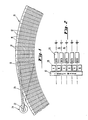
- the magnetizeable surface of the disk 10 is divided by address marks 12 (also referred to as index or timing marks) into sectors 14.
- address marks 12 also referred to as index or timing marks
- floppy 8-inch so-called "floppy" disk is divided into 70 sectors.
- the address marks are permanently written on the floppy disk at the time of its manufacture, as may be position information to be discussed below in connection with Fig. 2, which defines the position of the tracks indicated generally at 16 for the writing of data thereto.
- the index marks do not vary with respect to the tracks.
- Juxtaposed to the disk 10 is a read/write head indicated generally at 18 carried by a servo arm 20, pivoted about an axis 22 under the influence of a servo motor indicated generally at 24.
- the read/write head 18 picks up position information written in proximity to each of the'.3index marks 12, and circuitry to be discussed below in connection with Fig. 3 uses this position information to provide suitable control signals to the motor 24.
- the position of the head 18 with respect to the track 16 is controlled both as to centering when a particular track is to be accessed and as to moving the head from one track to the other during a seek operation.
- Our co-pending application no. (Serial no. ), referred to above, describes the centering operation.
- the present application relates to the seek operation.
- the servo motor 24 When a command is received by the disk drive to the effect that a track other than that to which the head is at present juxtaposed is to be accessed, the servo motor 24 must be controlled to rotate the arm 20 carrying the head 18 about the axis 22 so as to reach the sought for track. As will be apparent from Fig. 1, as the disk 10 rotates with respect to the head 18 various address marks 12 and data fields pass thereunder. By detection of the position information by the head, the circuitry at all times "knows" where it is both with respect to its radial track location, and with respect to which sector of the track is juxtaposed to the head at any given time, thus completing the servo loop.
- Fig. 2 shows details of the position information written at the beginning of each data field for each sector which is used in the control of the seek operation.
- An index mark 12 extends across the disk at the beginning of each sector without regard to track location.
- the centre lines of the tracks 16 are shown; data fields 26 are centered thereon.
- position information signals 28 referred to as A and B, as they vary from one another in order to enable appropriate decoding of the position information, as fully discussed in the co-pending application referred to above.
- Additional position information centered on the track would also typically be provided, again as discussed in the co-pending application referred to above; detailed discussion of that information is not required for an understanding of the present invention.
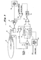
- Fig. 3 shows circuitry useful in practising the method of the present invention. Much of the circuitry shown in Fig. 3 is in common with that described in the co-pending application referred to above.
- the servo motor 24 is controlled in accordance with signals supplied to it from a power amplifier 30 to move the read/write head 18 carried by the servo arm 20 with respect to the disk 10.
- the read/write head 18 picks up position as well as data signals from the disk 10; the position signals are passed to an automatic gain control amplifier 32 controlled in accordance with the output of a summing node 34, adding the A and B position signals together in order to maintain the overall amplitude of the position signal information at a constant level.
- the A and B position signals are passed to an A detector 36 and a B detector 38, respectively, under the control of window detector logic 40, which in accordance with detection of the timing mark and a clock signal signifies which of the A and B signals is expected at any given time.
- the A and B signals are subtracted from one another in a node 42; the A - B signal, which is zero when the head is properly centered between the A and B position information, is passed to a sample and hold element 44. The output of this element 44, the position error signal, is then passed to a comparator 46 where it is compared with a command signal. If the head is to remain at the centre of the track, the "centering" command signal would ordinarily be zero; if the position error signal is likewise zero, no signal will be passed to the power amplifier 30, which connection completes the loop. If, on the other hand, there is a position error signal, the power amplifier will be controlled to operate the servo motor 24 to vary the relative position of the head with respect to the disk.
- servo motor may be likewise controlled by the power amplifier during the seek operation.
- Fig. 3 shows seek control logic 48, to be discussed in further detail below, providing an input to the power amplifier.
- the seek control logic also provides the centering command to the comparator 46.
- the output of the sample and hold element 44 to the comparator 46 is a signal indicative of the relative position of the read/write head with respect to the centre of the track whenever the head is juxtaposed to the A and B position signals. If during a seek operation, the trajectory of the head with respect to the sector is such that it does not pass precisely over the centre of the track while the A and B position signals are juxtaposed to the head, a position error signal will be generated.
- the seek control logic 48 provides a centering command to the comparator taking this into account.
- the circuitry of Fig. 3 will provide an automatic additional correction to the power amplifier 30 for supply to the servo motor 24 using precisely the same circuit elements and position information as used ordinarily to control the centering of the head with respect to the disk.
- a read/write head mounted on an arm pivoting about an axis spaced from the disk i.e. a "record player” type arm, as distinguished from one always tangent to the data track, can be controlled so that the track spacing is equal, that is, by varying the increments of the arm's angular rotation about its axis per track, or so that the angular increments are equal, thus varying the track spacing, the inner tracks being closer together.
- the second possibility is chosen; that is, the servo motor is controlled so that the angular increments of arm rotation per track is equal. The inner tracks on the disk will thus be spaced more closely together. Control of the servo motor thus realized is greatly simplified.
- each "jump" between tracks of identical spacing is the same, regardless of the actual initial and final track positions of the head and of whether the jump is clockwise or counter-clockwise with respect to the axis of the servo motor. Accordingly, the number of individual head trajectories which must be provided for is equal to the number of tracks less one. In a preferred embodiment 306 tracks are accessible by the head, so that 305 possible trajectories must be provided for.
- the method generally employed to operate a servo motor under microprocessor control involves the stepping of the current supplied to the motor through a series of steps under the control of the processor. That is, the processor outputs a series of commands which are compared with a signal physically output by the mechanical apparatus under control, so as to provide a servo loop. For each trajectory a relatively extensive series of commands is required if the head is to be moved from track to track with reasonable speed. Accordingly, it will be appreciated that to store each step of each trajectory in, for example, a read only memory (ROM) for each of the 305 possible trajectories would require enormous quantities of ROM.
- ROM read only memory
- the trajectories are individually and adaptively calculated for each seek operation, the calculation proceeding even after the operation is begun. Only in a few short jump situations, where there is insufficient time to complete the calculation are each of the commands to be output by the microprocessor to the servo motor stored in a look-up table or read only memory (ROM) and not calculated. Instead, typical accelerate and decelerate profiles are stored in.ROM and the appropriate portions of these.profiles to be used are selected by the microprocessor and are written by it to a table of commands stored in random-access memory (RAM).
- RAM random-access memory
- Coast instructions corresponding to portions of the trajectory in which the head is supplied with drive power only as necessary to keep moving at constant velocity are interspersed between the accelerate and decelerate profiles in order to generate the total profile for the given seek operation.
- One or more coast commands may additionally be interspersed in the decelerate section of the profile, so as to ensure that the head arrives at the appropriate track after a smooth and gradual deceleration.
- Fig. 4 shows a detailed flowchart of the method whereby the profile for traverse of any given number of tracks N T is calculated.
- N T is supplied by the disk controller, initiating the seek routine. If N T > N C , N C being equal to the minimum number of tracks for which a profile calculable, determined on the basis of the time taken for the calculation, the calculation is begun. If not, a profile of this traverse stored in read-only memory (ROM) at the time of construction of the disk drive is moved to random access memory (RAM) which is accessed by the microprocessor to supply commands to the circuitry shown in Fig. 3 for performance.
- ROM read-only memory
- RAM random access memory
- N T the number of tracks to be traversed
- N min the minimum number of tracks for which the maximum velocity of the servo system is reached. If the answer to this question is yes, it is desirable that the acceleration to that speed be as rapid as possible. Accordingly, the full acceleration profile is moved from ROM to RAM and performance begun. Next, N A , the number of tracks traversed during performance of the full acceleration profile, and N D , the number traversed during deceleration from maximum velocity, are subtracted from NT' leaving the remaining number of tracks, N REM . N REM is divided by a constant, the constant being indicative of the maximum velocity of the servo system.
- the quotient of this division is equal to the number of coasts, that is, the number of steps during which neither acceleration nor deceleration is supplied to the servo motor.
- the velocity is then maintained at its constant speed by the position error signal derived in accordance with the circuit discussed above in connection with Fig. 3.
- the maximum velocity of the servo is some integral number of tracks traversed per sector traversed (hereinafter tracks/sector) so that as much position information is derived from each sector as possible.
- tracks/sector integral number of tracks traversed per sector traversed
- N The quotient of the division of N REM by the constant may be termed N , the number of coasts interposed between the acceleration and deceleration operations. N is written to RAM and used to control this portion of the velocity profile. The remainder of this division determines the location of additional coasts interposed in the deceleration profile to ensure that the head is smoothly decelerated to a stop over the appropriate track from its maximum velocity. That is, the size of the remainder, in tracks, is equated to that location in the decelerate profile at which an additional coast step is inserted.. The total deceleration profile is then written to RAM, thus completing calculation of the overall velocity profile.
- N T is divided by a constant, typically 2. That is, the total number of tracks is divided between acceleration and deceleration, which are performed at equal rates. The integral portion of this quotient then determines the number of tracks each traversed during acceleration and deceleration, and the appropriate portions of the acceleration and deceleration profiles stored in ROM are then written to RAM. The remainder from this division is then treated in the same way as that discussed above with respect to the division of N REM by a constant, that is, the remainder is used to determine the location of coast sectors in the deceleration profile, which is then written to RAM for execution.
- the trajectory taken by the servo in moving from one track to another is chosen to achieve this jump in the minimum time. Accordingly, while the only servo position information available to ensure that the trajectory is being followed correctly is that written immediately after each index mark, it is important to make some correction to the servo circuit to allow for the possibility that the read/write head is not exactly positioned over the centre line of the track when the position error information immediately following the index mark passes the head.
- a position error correction signal is generated by the microprocessor and fed to the comparator which is used in the control of the head with respect to the centre line of the track, so that the output of this circuit is indicative that the trajectory is being followed accurately, even where it does not coincide with the centre of the track at the position of the address information, as discussed above in connection with Fig. 1.
- Table I shows the overall profile of a seek operation in a traverse of some 31 tracks. The seek is performed such that a total of 25 sectors pass beneath the read/write head during a traverse of the 31 tracks. The Table shows that the first 11 sectors are traversed in a constant acceleration mode, so that the velocity of the servo (expressed in tracks per sector) continually increases. A first deceleration ..
- each individual profile (save the very shortest) is individually generated each time the seek operation is sought to be performed.
- the invention utilizes the fact that the initial few steps of each seek operation are always acceleration in order to obtain time to perform the calculation of the remainder of the profile.
- the microprocessor controlling the operation selects portions of stored acceleration and deceleration profiles and uses.these together with a calculated number of coast operations, in which the velocity of the servo head is maintained constant, to generate the total profile.
- the invention may have applicability to other forms of servo systems.
- the arrangement described thus provides a servo circuit for controlling the motion of a read/write head with respect to a disk during a seek operation which requires minimal additional components to be added to the circuitry used to control the centering of the head over a desired track: individual profiles are not stored, so that large quantities of memory are not required.
- the seek operation is readily implementable at no cost to performance.
Landscapes
- Moving Of Head For Track Selection And Changing (AREA)
Applications Claiming Priority (2)
| Application Number | Priority Date | Filing Date | Title |
|---|---|---|---|
| US06/257,484 US4439800A (en) | 1981-04-24 | 1981-04-24 | Servo control of seek operation in magnetic disk drive |
| US257484 | 1981-04-24 |
Publications (2)
| Publication Number | Publication Date |
|---|---|
| EP0063936A1 true EP0063936A1 (fr) | 1982-11-03 |
| EP0063936B1 EP0063936B1 (fr) | 1986-10-15 |
Family
ID=22976488
Family Applications (1)
| Application Number | Title | Priority Date | Filing Date |
|---|---|---|---|
| EP82302102A Expired EP0063936B1 (fr) | 1981-04-24 | 1982-04-23 | Dispositif pour la régulation de position |
Country Status (7)
| Country | Link |
|---|---|
| US (1) | US4439800A (fr) |
| EP (1) | EP0063936B1 (fr) |
| JP (1) | JPS57183673A (fr) |
| AU (2) | AU549858B2 (fr) |
| CA (1) | CA1189187A (fr) |
| DE (1) | DE3273856D1 (fr) |
| MX (1) | MX152064A (fr) |
Cited By (2)
| Publication number | Priority date | Publication date | Assignee | Title |
|---|---|---|---|---|
| EP0103493A1 (fr) * | 1982-09-15 | 1984-03-21 | Ampex Corporation | Générateur de commande de la vitesse réglé à deux échelons |
| EP0114509B1 (fr) * | 1982-12-28 | 1987-06-03 | Kabushiki Kaisha Toshiba | Appareil de reproduction de disque d'enregistrement |
Families Citing this family (17)
| Publication number | Priority date | Publication date | Assignee | Title |
|---|---|---|---|---|
| JPS57117162A (en) * | 1981-01-09 | 1982-07-21 | Toshiba Corp | Positioning device for magnetic head |
| US4486797A (en) * | 1982-11-22 | 1984-12-04 | International Business Machines Corporation | Sliding mask variable resolution velocity trajectory for track following servo |
| US4600868A (en) * | 1983-05-09 | 1986-07-15 | Bryant Lawrence M | Open loop acceleration/deceleration control for disk drive stepper motors |
| US4751441A (en) * | 1985-05-31 | 1988-06-14 | Cambrian Consultants, Inc. | Transducer position control system for disk storage equipment |
| JPS6252772A (ja) * | 1985-08-30 | 1987-03-07 | Toshiba Corp | 磁気ヘツド制御方式 |
| JP2593437B2 (ja) * | 1985-09-24 | 1997-03-26 | 株式会社東芝 | 磁気デイスクのサーボ位置決め装置 |
| GB2188720B (en) * | 1986-04-04 | 1990-12-19 | Data Recording Instr Co | Improved position control system |
| EP0247829A1 (fr) * | 1986-05-26 | 1987-12-02 | Pioneer Electronic Corporation | Méthode et appareil pour corriger le gain de rétroaction d'une servo-boucle à réglage fin |
| WO1988002913A1 (fr) * | 1986-10-14 | 1988-04-21 | Maxtor Corporation | Procede et appareil de commande de la position d'un assemblage de tete mobile |
| US5450202A (en) * | 1988-11-17 | 1995-09-12 | Tisue; James G. | Adaptive resonant positioner having random access capability |
| US5268802A (en) * | 1991-05-28 | 1993-12-07 | Iomega Corporation | Reading non-standard tapes on tape drives |
| US5191297A (en) * | 1991-07-25 | 1993-03-02 | Iomega Corporation | Transconductance amplifier having sensfets which drive a load with linearly proportional current |
| US5381279A (en) * | 1993-10-13 | 1995-01-10 | Maxtor Corporation | Disk drive system with adjustable spindle and actuator power to improve seek and access performance |
| US5793555A (en) * | 1996-12-13 | 1998-08-11 | International Business Machines Corporation | Seek optimization for disk files with side-by-side head |
| US6031698A (en) * | 1997-06-10 | 2000-02-29 | Iomega Corporation | Multiple partition tape cartridge detection means |
| WO2003052758A1 (fr) * | 2001-12-13 | 2003-06-26 | Seagate Technology Llc | Commande d'acceleration d'un reseau d'unites de stockage raid |
| US6937431B2 (en) | 2002-04-09 | 2005-08-30 | Seagate Technology Llc | Matching peak velocities of acceleration and deceleration seek profiles in a disc drive |
Citations (4)
| Publication number | Priority date | Publication date | Assignee | Title |
|---|---|---|---|---|
| US3699555A (en) * | 1970-10-23 | 1972-10-17 | Zerox Corp | Apparatus for rapid action displacement control |
| GB2011654A (en) * | 1977-12-30 | 1979-07-11 | Ibm | Servo systems |
| EP0013326A2 (fr) * | 1978-12-27 | 1980-07-23 | International Business Machines Corporation | Système de servo-positionnement à échantillonnage de données et son application dans une pile de disques à secteurs de servocommande |
| US4237502A (en) * | 1979-07-10 | 1980-12-02 | Per Sci, Inc. | Disk drive system |
Family Cites Families (3)
| Publication number | Priority date | Publication date | Assignee | Title |
|---|---|---|---|---|
| DE2258382A1 (de) * | 1972-11-29 | 1974-06-06 | Ibm Deutschland | Regeleinrichtung zur steuerung der bewegung eines einstellelementes |
| GB1520350A (en) * | 1976-12-22 | 1978-08-09 | Ibm | Data storage apparatus |
| US4272793A (en) * | 1979-06-04 | 1981-06-09 | Texas Instruments Incorporated | System and method for positioning a magnetic head transducer on a flexible storage media |
-
1981
- 1981-04-24 US US06/257,484 patent/US4439800A/en not_active Expired - Lifetime
-
1982
- 1982-04-21 AU AU82912/82A patent/AU549858B2/en not_active Ceased
- 1982-04-23 CA CA000401576A patent/CA1189187A/fr not_active Expired
- 1982-04-23 EP EP82302102A patent/EP0063936B1/fr not_active Expired
- 1982-04-23 DE DE8282302102T patent/DE3273856D1/de not_active Expired
- 1982-04-23 MX MX192408A patent/MX152064A/es unknown
- 1982-04-24 JP JP57069437A patent/JPS57183673A/ja active Pending
-
1986
- 1986-02-11 AU AU53400/86A patent/AU5340086A/en not_active Abandoned
Patent Citations (4)
| Publication number | Priority date | Publication date | Assignee | Title |
|---|---|---|---|---|
| US3699555A (en) * | 1970-10-23 | 1972-10-17 | Zerox Corp | Apparatus for rapid action displacement control |
| GB2011654A (en) * | 1977-12-30 | 1979-07-11 | Ibm | Servo systems |
| EP0013326A2 (fr) * | 1978-12-27 | 1980-07-23 | International Business Machines Corporation | Système de servo-positionnement à échantillonnage de données et son application dans une pile de disques à secteurs de servocommande |
| US4237502A (en) * | 1979-07-10 | 1980-12-02 | Per Sci, Inc. | Disk drive system |
Non-Patent Citations (1)
| Title |
|---|
| PATENTS ABSTRACTS OF JAPAN, vol.4, no.118, August 22, 1980, page 90P24 & JP-A-55 073 970 (FUJITSU K.K.) (04-06-1980) * |
Cited By (2)
| Publication number | Priority date | Publication date | Assignee | Title |
|---|---|---|---|---|
| EP0103493A1 (fr) * | 1982-09-15 | 1984-03-21 | Ampex Corporation | Générateur de commande de la vitesse réglé à deux échelons |
| EP0114509B1 (fr) * | 1982-12-28 | 1987-06-03 | Kabushiki Kaisha Toshiba | Appareil de reproduction de disque d'enregistrement |
Also Published As
| Publication number | Publication date |
|---|---|
| CA1189187A (fr) | 1985-06-18 |
| US4439800A (en) | 1984-03-27 |
| AU5340086A (en) | 1986-07-17 |
| DE3273856D1 (en) | 1986-11-20 |
| EP0063936B1 (fr) | 1986-10-15 |
| MX152064A (es) | 1985-05-27 |
| JPS57183673A (en) | 1982-11-12 |
| AU8291282A (en) | 1982-10-28 |
| AU549858B2 (en) | 1986-02-20 |
Similar Documents
| Publication | Publication Date | Title |
|---|---|---|
| EP0063936A1 (fr) | Dispositif pour la régulation de position | |
| EP0442650B1 (fr) | Mémoire à disque avec correction adaptive de l'ovalisation non répétitive du disque | |
| US6850385B1 (en) | Repeated servo runout error compensation in a disc drive | |
| US4816941A (en) | Disk file digital servo control system with optimized sampling rate | |
| US4333117A (en) | Disc head arm position controller using digital velocity sensing | |
| US4622604A (en) | Magnetic head controlling apparatus | |
| US6313964B1 (en) | Early write enable with off-track write protection | |
| EP0308070B1 (fr) | Fichier à guide d'enregistrement de données avec commande d'asservissement numérique | |
| KR0178510B1 (ko) | 싱글 스테이지 탐색방법 및 렌즈어셈블리 제어회로 | |
| EP0463820A2 (fr) | Appareil d'entraînement de disque et méthodes de recherche pour pistes spirales | |
| US4532562A (en) | Servo control of seek operation in magnetic disk drive | |
| JPH01124170A (ja) | 磁気ディスク装置 | |
| KR890004265B1 (ko) | 인덱스 서어보 시스템에 의한 자기디스크장치의 자기헤드 제어시스템 | |
| KR920006123B1 (ko) | 자기 디스크 구동 장치 및 자기 헤드 위치 설정 방법 | |
| EP0357044B1 (fr) | Dispositif de commande d'une opération d'accès pour un appareil d'enregistrement et de lecture d'information | |
| CN100370548C (zh) | 磁盘驱动器及其制造方法 | |
| EP0683488A1 (fr) | Méthode de mesure de la vitesse linéaire d'un disque | |
| JPS6117061B2 (fr) | ||
| JPH02304777A (ja) | 磁気デイスク装置の制御装置 | |
| JPS598170A (ja) | ヘツド移動方式 | |
| KR100224662B1 (ko) | 디스크 트랙점프방법 | |
| US5043961A (en) | Transducer access control system | |
| JPH06349214A (ja) | 磁気ディスク装置及び位置制御方法 | |
| JP2547599B2 (ja) | ディスク再生装置 | |
| JPH05120701A (ja) | 光デイスクドライブ |
Legal Events
| Date | Code | Title | Description |
|---|---|---|---|
| PUAI | Public reference made under article 153(3) epc to a published international application that has entered the european phase |
Free format text: ORIGINAL CODE: 0009012 |
|
| AK | Designated contracting states |
Designated state(s): BE CH DE FR GB IT NL SE |
|
| 17P | Request for examination filed |
Effective date: 19830419 |
|
| ITF | It: translation for a ep patent filed | ||
| GRAA | (expected) grant |
Free format text: ORIGINAL CODE: 0009210 |
|
| AK | Designated contracting states |
Kind code of ref document: B1 Designated state(s): BE CH DE FR GB IT LI NL SE |
|
| RAP2 | Party data changed (patent owner data changed or rights of a patent transferred) |
Owner name: IOMEGA CORPORATION |
|
| REF | Corresponds to: |
Ref document number: 3273856 Country of ref document: DE Date of ref document: 19861120 |
|
| ET | Fr: translation filed | ||
| PG25 | Lapsed in a contracting state [announced via postgrant information from national office to epo] |
Ref country code: SE Effective date: 19870424 |
|
| PG25 | Lapsed in a contracting state [announced via postgrant information from national office to epo] |
Ref country code: LI Effective date: 19870430 Ref country code: CH Effective date: 19870430 |
|
| PLBE | No opposition filed within time limit |
Free format text: ORIGINAL CODE: 0009261 |
|
| STAA | Information on the status of an ep patent application or granted ep patent |
Free format text: STATUS: NO OPPOSITION FILED WITHIN TIME LIMIT |
|
| 26N | No opposition filed | ||
| BERE | Be: lapsed |
Owner name: IOMEGA CORP. Effective date: 19870430 |
|
| PG25 | Lapsed in a contracting state [announced via postgrant information from national office to epo] |
Ref country code: NL Effective date: 19871101 |
|
| NLV4 | Nl: lapsed or anulled due to non-payment of the annual fee | ||
| REG | Reference to a national code |
Ref country code: CH Ref legal event code: PL |
|
| PG25 | Lapsed in a contracting state [announced via postgrant information from national office to epo] |
Ref country code: BE Effective date: 19890430 |
|
| PGFP | Annual fee paid to national office [announced via postgrant information from national office to epo] |
Ref country code: GB Payment date: 19910416 Year of fee payment: 10 |
|
| PGFP | Annual fee paid to national office [announced via postgrant information from national office to epo] |
Ref country code: FR Payment date: 19910425 Year of fee payment: 10 |
|
| PGFP | Annual fee paid to national office [announced via postgrant information from national office to epo] |
Ref country code: DE Payment date: 19910627 Year of fee payment: 10 |
|
| PG25 | Lapsed in a contracting state [announced via postgrant information from national office to epo] |
Ref country code: GB Effective date: 19920423 |
|
| GBPC | Gb: european patent ceased through non-payment of renewal fee | ||
| PG25 | Lapsed in a contracting state [announced via postgrant information from national office to epo] |
Ref country code: FR Effective date: 19921230 |
|
| PG25 | Lapsed in a contracting state [announced via postgrant information from national office to epo] |
Ref country code: DE Effective date: 19930101 |
|
| REG | Reference to a national code |
Ref country code: FR Ref legal event code: ST |
|
| EUG | Se: european patent has lapsed |
Ref document number: 82302102.7 Effective date: 19880906 |