EP0011722B1 - Procédé et dispositif de réglage digital pour obtenir des reproductions en couleurs - Google Patents
Procédé et dispositif de réglage digital pour obtenir des reproductions en couleurs Download PDFInfo
- Publication number
- EP0011722B1 EP0011722B1 EP79104229A EP79104229A EP0011722B1 EP 0011722 B1 EP0011722 B1 EP 0011722B1 EP 79104229 A EP79104229 A EP 79104229A EP 79104229 A EP79104229 A EP 79104229A EP 0011722 B1 EP0011722 B1 EP 0011722B1
- Authority
- EP
- European Patent Office
- Prior art keywords
- printing
- ink
- colours
- record medium
- colour
- Prior art date
- Legal status (The legal status is an assumption and is not a legal conclusion. Google has not performed a legal analysis and makes no representation as to the accuracy of the status listed.)
- Expired
Links
- 238000000034 method Methods 0.000 title claims description 16
- 230000033458 reproduction Effects 0.000 title description 8
- 239000003086 colorant Substances 0.000 claims description 57
- 239000000976 ink Substances 0.000 claims description 46
- 238000007639 printing Methods 0.000 claims description 42
- 239000011159 matrix material Substances 0.000 claims description 10
- 239000000654 additive Substances 0.000 claims description 9
- 230000000996 additive effect Effects 0.000 claims description 9
- 230000015572 biosynthetic process Effects 0.000 claims description 7
- 239000000203 mixture Substances 0.000 claims description 5
- 230000007246 mechanism Effects 0.000 claims description 3
- 230000003595 spectral effect Effects 0.000 claims description 3
- 239000000758 substrate Substances 0.000 claims description 3
- 230000008021 deposition Effects 0.000 claims 4
- 238000005286 illumination Methods 0.000 claims 1
- 238000012937 correction Methods 0.000 description 9
- 241001136792 Alle Species 0.000 description 5
- 239000003990 capacitor Substances 0.000 description 4
- 238000000926 separation method Methods 0.000 description 4
- 230000010339 dilation Effects 0.000 description 3
- 238000004519 manufacturing process Methods 0.000 description 3
- 238000010586 diagram Methods 0.000 description 2
- 238000001035 drying Methods 0.000 description 2
- 230000003287 optical effect Effects 0.000 description 2
- 238000012546 transfer Methods 0.000 description 2
- 238000003491 array Methods 0.000 description 1
- 230000005540 biological transmission Effects 0.000 description 1
- 239000013078 crystal Substances 0.000 description 1
- 238000011161 development Methods 0.000 description 1
- 238000002845 discoloration Methods 0.000 description 1
- 238000006073 displacement reaction Methods 0.000 description 1
- 238000005516 engineering process Methods 0.000 description 1
- 230000007613 environmental effect Effects 0.000 description 1
- 238000011835 investigation Methods 0.000 description 1
- 239000007788 liquid Substances 0.000 description 1
- 238000012806 monitoring device Methods 0.000 description 1
- 238000012544 monitoring process Methods 0.000 description 1
- 239000000825 pharmaceutical preparation Substances 0.000 description 1
- 229940127557 pharmaceutical product Drugs 0.000 description 1
- 238000007650 screen-printing Methods 0.000 description 1
- 230000007704 transition Effects 0.000 description 1
- 230000007723 transport mechanism Effects 0.000 description 1
Images

Classifications
-
- H—ELECTRICITY
- H04—ELECTRIC COMMUNICATION TECHNIQUE
- H04N—PICTORIAL COMMUNICATION, e.g. TELEVISION
- H04N1/00—Scanning, transmission or reproduction of documents or the like, e.g. facsimile transmission; Details thereof
- H04N1/46—Colour picture communication systems
- H04N1/50—Picture reproducers
-
- B—PERFORMING OPERATIONS; TRANSPORTING
- B41—PRINTING; LINING MACHINES; TYPEWRITERS; STAMPS
- B41J—TYPEWRITERS; SELECTIVE PRINTING MECHANISMS, i.e. MECHANISMS PRINTING OTHERWISE THAN FROM A FORME; CORRECTION OF TYPOGRAPHICAL ERRORS
- B41J2/00—Typewriters or selective printing mechanisms characterised by the printing or marking process for which they are designed
- B41J2/005—Typewriters or selective printing mechanisms characterised by the printing or marking process for which they are designed characterised by bringing liquid or particles selectively into contact with a printing material
- B41J2/01—Ink jet
- B41J2/21—Ink jet for multi-colour printing
- B41J2/2132—Print quality control characterised by dot disposition, e.g. for reducing white stripes or banding
- B41J2/2135—Alignment of dots
-
- B—PERFORMING OPERATIONS; TRANSPORTING
- B41—PRINTING; LINING MACHINES; TYPEWRITERS; STAMPS
- B41J—TYPEWRITERS; SELECTIVE PRINTING MECHANISMS, i.e. MECHANISMS PRINTING OTHERWISE THAN FROM A FORME; CORRECTION OF TYPOGRAPHICAL ERRORS
- B41J2/00—Typewriters or selective printing mechanisms characterised by the printing or marking process for which they are designed
- B41J2/005—Typewriters or selective printing mechanisms characterised by the printing or marking process for which they are designed characterised by bringing liquid or particles selectively into contact with a printing material
- B41J2/01—Ink jet
- B41J2/17—Ink jet characterised by ink handling
- B41J2/18—Ink recirculation systems
- B41J2/185—Ink-collectors; Ink-catchers
Definitions
- the invention relates to a method for digitally controlling the formation of colored reproductions for raster printing, and to an apparatus for carrying out this method.
- screen printing is to be understood to mean that a finite number of colored halftone picture elements are printed, the selection being made in such a way that the human eye is more similar due to its own resolution capability and its previous experience in viewing Images tend to be deceived and thus seem to see a picture with a continuous color transition and not a rasterized, i.e. H. «Broken» color image.
- the picture elements are put together sequentially by printing the required colors in the form of dots. These dots are placed side by side so that they form print lines, and a sufficiently large number of print lines are arranged one below the other to form the whole image.
- the parallel printing process is inherently very slow.
- the serial printing process is much faster, but more difficult.
- the first type is the impact printer, in which a column or matrix of wires is arranged in a common printhead which can be individually operated to be pressed against an ink ribbon which in turn is pressed against the recording medium at a point thereon to create.
- the ribbon is designed as a multicolor ribbon and contains the required number of printing inks and black.
- a ribbon lift mechanism is responsible for presenting the color on the wire matrix of the print head that is to be printed or overprinted.
- this printer Because of its speed, this printer has the best prerequisites for use in a color image display system.
- a color image display system can either be a color copying machine or a color image faximile transmission system, which depends on the distance between the scanner and the printer.
- the present invention is also applicable to independent ink jet printers, it is described below using the example of a color image reproduction system, namely a color copier.
- the color image original is first broken down into its additive primary colors green, blue and red by means of a bandpass filter, in that the color “amplitude”, ie. H. Color intensity for all picture elements is measured in an x-y grid of the original. Intensities below a certain threshold are neglected.
- the subtractive primary colors magenta (absorbs green), yellow (absorbs blue) and cyan (absorbs red) are used to reconstruct the image on a white recording medium.
- the halftone patterns corresponding to these subtractive primary colors must be exactly overlaid on the copy in the same xy position as in the original, but the grid of colors must be rotated with respect to the horizontal. This requirement can be met with the conventional analog or digital color image reproduction techniques that use rotated screens are not met. Therefore, the fidelity of conventional color reproduction is poor and its correction requires complex and difficult to implement measures to achieve the color balance.
- a method for scanning coded color rings is described in Swiss patent specification 495.017 in connection with a method for identifying ampoules which contain pharmaceutical products of various types.
- the ampoules have rings in the colors red, green, blue, cyan, magenta and yellow.
- the scanner uses dichroic mirrors to split the light reflected from the rings into three spectral regions (red, green, blue), and the color signals supplied by three photomultipliers and exceeding a predetermined threshold value are digitized using a self-clocking system. In this patent, however, no reconstruction mechanism for the scanned color is shown, i. H. a printer is not described.
- the Swiss patent 537.757 relates to an ink jet printer with a print head which has a plurality of parallel nozzles in a linear or matrix arrangement.
- the patent describes the formation of a double feed chamber and briefly mentions the alignment of the drops emitted by various parallel nozzles by delaying the actuation of the nozzles so that the drops reach the recording medium at the correct position.
- the possibility of using different colors for printing is mentioned, whereby the colors can either mix on the recording medium or be placed next to one another.
- Multi-color printing with inkjet printers uses either the "additive” or “subtractive” method, depending on which group of primary colors is used.
- the use of the additive primary colors red, yellow and blue is proposed in the above-mentioned Swiss patent 468.630.
- the present invention prefers the use of the subtractive primary colors magenta, yellow and cyan.
- magenta which absorbs green
- yellow which absorbs blue
- magenta and cyan which absorbs red
- the superposition yellow and cyan gives green
- the superposition of all three colors gives black .
- Fig. 1 shows a playback device constructed from conventional elements, with which the invention to be described can be used.
- An original 1 is illuminated by a light source 2 and scanned with a scanner 3, the scanning position of which is controlled by a control unit 4 such that it scans the picture elements of the original 1 sequentially.
- the optical output signal of the scanner 3 is now broken down into its additive primary colors green, blue and red in the sense of a bandpass filter by passing it through dispersive means, such as a first dichroic mirror 5 which eliminates the green component and a second dichroic mirror 6, which eliminates the blue component from the output signal of the scanner.
- the green and blue components, which are reflected by the dichroic mirrors 5 and 6, as well as the red component, which has passed through both mirrors 5 and 6, are amplified by means of photomultipliers 7, 8 and 9 individually assigned to the color channels.
- the electrical output signals of the photomultipliers 7, 8 and 9 are passed through threshold circuits 10, 11 and 12. These are clocked by a common clock generator 13, which is also connected to the position control unit 4.
- the output signals of the threshold circuits 10, 11 and 12 therefore represent the digitized values of the hue of the green, blue and red components of each picture element of the original 1.
- these hue values of the additive primary colors are first converted into their equivalent halftone representations.
- the digitized hue value is quantized into an appropriate number of amplitude values and these are compared to predetermined threshold values to produce binary output signals which indicate whether the color in question at the scanned location exceeds the threshold values.
- the raster of the picture element matrix has to be rotated with respect to the horizontal in order to avoid an undesired moire pattern.
- the algorithm for the generation of a 45 ° rotation as in the present case, is simple and obvious to the person skilled in the art. The inventor has published an instruction for digitally generating rotations of any size in IBM Technical Disclocure Bulletin Volume 20 No. 6, November 1977, pages 2423-2425.
- the resulting binary output signals which are representative of the intensities of the additive primary colors, are used to control their corresponding subtractive primary colors, ie the "green " signal controls the printing of magenta, the "blue” signal controls the printing of yellow, the “red” signal controls the printing of cyan, which is controlled by conventional print control units 14, 15 and 16, the outputs of which are connected to a multicolor inkjet printer 17.
- Printer 17 has all of the elements generally found in any conventional ink jet printer, such as a reservoir ink feed device, proper ink pressure maintaining means, drop generating and deflecting means.
- the printer 17 has its own nozzle 18, 19, 20 for each printing ink and, if necessary, an additional nozzle 21 for black to improve the contrast.
- nozzles are oriented so that the drops they dispense, which are intended for the same x, y coordinate of the picture element to be reconstructed, reach the recording medium 22 at different times, the intermediate time intervals for drying the ink and transporting the recording medium 22 can be used.
- the printer 17 and the transport mechanism (not shown) for the record carrier 22 receive control signals from the control unit 4 which ensure that the correspondence between the x, y printing position and the x, y scanning position is maintained.
- the invention therefore teaches the continuous monitoring of the impression on the recording medium and the development of a suitable correction signal with which the position of the Printer 17 can be corrected with respect to the recording medium 22 and to influence the delivery times of the second and third printing ink.
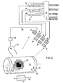
- FIG. 2 schematically shows a first exemplary embodiment of a monitoring device according to the present invention.
- the record carrier 22 is held on a suitable support, such as a rotating drum 23.
- the drum 23 is driven in the direction of the arrow 23 by conventional, controllable drive means (not shown).
- Part 25 of the reproduced image consists of a plurality of printed dots, which are shown as squares 26 for the sake of simplicity.
- Each of the printed dots is illuminated by a flash of white light from a stroboscope 27, and the light reflected by the recording medium 22, which has passed through the printing inks present on the relevant printed dot 26, is passed through a group of filters, namely magenta filters 28.
- a fourth light detector surface 34 is provided for scanning the spatial position of the overlying halftone patterns.
- the area 34 provides an output signal via a line 35 to a stroboscope control unit 36 which controls the flash frequency in order to keep the halftone patterns in the center of the detector areas 31 to 33.
- the output signals supplied by the surfaces 31 to 33 are fed to a delay network 37, which is composed of tapped shift registers 38, 39 and 40, the outputs of which are connected to a control unit 41, which in turn controls signals to the ink drop generator, i. H. supplies the piezoelectric crystal for the control of the drop frequency, to the pump for the control of the ink pressure, and to the deflection device, all for the correction of the ink jet in the y direction indicated by the arrow 42, and to the transport device of the ink jet print head, for the correction in the x direction indicated by arrow 43.
- a delay network 37 which is composed of tapped shift registers 38, 39 and 40, the outputs of which are connected to a control unit 41, which in turn controls signals to the ink drop generator, i. H. supplies the piezoelectric crystal for the control of the drop frequency, to the pump for the control of the ink pressure, and to the deflection device, all for the correction of the ink jet in the y direction indicated by the
- the stroboscope 27 is only switched on during the application of the second or following color. In this way the generation of a large output signal for the color printed first is avoided.
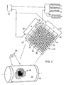
- Fig. 7 shows a further embodiment the optical device for detecting a positional deviation, in which the stroboscope 27 is replaced by a continuously white light-emitting light source 44, which can be an incandescent lamp, for example.
- the light reflected by the recording medium 22 and filtered by the printing ink printed thereon falls on an area scanner 45, which consists of an xy matrix - of light-sensitive elements 46, which are covered with filter masks 47 of different colors according to FIG. 7.
- the masks can consist of thin layers of colored film.
- the light-sensitive elements 46 can be designed, for example, as charge-coupled capacitors which store the light-generated charges.
- the capacitors 46 of each of the horizontal rows of arrays are connected to one of the common lines 48, 49, 50 and 51, which in turn are connected to a vertical (y) scan generator 52, while the capacitors 46 of each of the vertical columns of the array are connected to one of the common lines 53, 54, 55 and 56 are connected, which in turn are connected to a horizontal (x) scanning generator 57.
- the function of the stroboscope replaced in this exemplary embodiment is carried out by a pulsed lighting / reading circuit 59, which is controlled by a clock generator 60, which also controls the scan generators 52 and 57.
- the lighting / reading circuit 59 provides output signals for the control of the drop formation frequency, for the control of the ink pressure, for the control of the drop deflection device and for the control of the print head transport device on the basis of electronic sorting of the charge distribution for the second and following printed colors.
- the result of the scanning of the color printed first must be suppressed, which is done electronically in the embodiment described last.
Landscapes
- Engineering & Computer Science (AREA)
- Multimedia (AREA)
- Signal Processing (AREA)
- Quality & Reliability (AREA)
- Ink Jet (AREA)
- Fax Reproducing Arrangements (AREA)
- Facsimile Transmission Control (AREA)
- Facsimile Image Signal Circuits (AREA)
- Particle Formation And Scattering Control In Inkjet Printers (AREA)
Claims (4)
Applications Claiming Priority (2)
| Application Number | Priority Date | Filing Date | Title |
|---|---|---|---|
| CH12213/78 | 1978-11-29 | ||
| CH1221378A CH637331A5 (de) | 1978-11-29 | 1978-11-29 | Verfahren und vorrichtung zum digitalen steuern der bildung farbiger wiedergaben. |
Publications (3)
| Publication Number | Publication Date |
|---|---|
| EP0011722A2 EP0011722A2 (fr) | 1980-06-11 |
| EP0011722A3 EP0011722A3 (en) | 1981-01-21 |
| EP0011722B1 true EP0011722B1 (fr) | 1983-05-11 |
Family
ID=4380946
Family Applications (1)
| Application Number | Title | Priority Date | Filing Date |
|---|---|---|---|
| EP79104229A Expired EP0011722B1 (fr) | 1978-11-29 | 1979-10-31 | Procédé et dispositif de réglage digital pour obtenir des reproductions en couleurs |
Country Status (6)
| Country | Link |
|---|---|
| EP (1) | EP0011722B1 (fr) |
| JP (1) | JPS5574884A (fr) |
| CA (1) | CA1138521A (fr) |
| CH (1) | CH637331A5 (fr) |
| DE (1) | DE2965397D1 (fr) |
| IT (1) | IT1165338B (fr) |
Cited By (2)
| Publication number | Priority date | Publication date | Assignee | Title |
|---|---|---|---|---|
| DE3333801A1 (de) * | 1982-09-20 | 1984-03-22 | Sony Corp., Tokyo | Farbsignalverarbeitungsschaltung |
| DE3802736A1 (de) * | 1987-01-29 | 1988-08-18 | Toshiba Kk | Bilderzeugungsvorrichtung |
Families Citing this family (18)
| Publication number | Priority date | Publication date | Assignee | Title |
|---|---|---|---|---|
| US4403874A (en) * | 1980-03-25 | 1983-09-13 | Ramtek Corporation | Color printer and multi-ribbon cartridge therefor |
| JPS572163A (en) * | 1980-06-06 | 1982-01-07 | Canon Inc | Multicolor ink jet recording device |
| JPS5741967A (en) * | 1980-08-26 | 1982-03-09 | Canon Inc | Color ink jet recording device |
| JPS5741965A (en) * | 1980-08-26 | 1982-03-09 | Canon Inc | Color ink jet recording device |
| JPS5741966A (en) * | 1980-08-26 | 1982-03-09 | Canon Inc | Color ink jet recording device |
| JPS57100580A (en) * | 1980-12-15 | 1982-06-22 | Fuji Photo Film Co Ltd | Ink jet printer |
| JPH0666881B2 (ja) * | 1981-09-18 | 1994-08-24 | キヤノン株式会社 | カラ−画像処理装置 |
| US4683492A (en) * | 1983-03-08 | 1987-07-28 | Canon Kabushiki Kaisha | Method and apparatus for recording a full-color image with a plurality of colorants on the basis of a set of area factors for the colorants selected from a plurality of sets of area factors calculated from a plurality of sets of equations |
| US5191361A (en) * | 1983-03-08 | 1993-03-02 | Canon Kabushiki Kaisha | Image reproducing system |
| DE3408336A1 (de) * | 1983-03-08 | 1984-09-13 | Canon K.K., Tokio/Tokyo | Bildreproduktionssystem |
| DE3526133A1 (de) * | 1985-07-22 | 1987-01-29 | Hell Rudolf Dr Ing Gmbh | Verfahren zur herstellung von farbbildern |
| US4853768A (en) * | 1985-12-26 | 1989-08-01 | Canon Kabushiki Kaisha | Color image processing apparatus with linear masking circuit having coefficients which vary in accordance with the levels of color component signals |
| JP2840323B2 (ja) * | 1989-09-28 | 1998-12-24 | キヤノン株式会社 | カラー画像記録装置 |
| NL9400355A (nl) * | 1994-03-07 | 1995-10-02 | Stork Colorproofing | Werkwijze voor het registreren van kleurdeelbeelden en daarmee verkregen patroon van afbeeldingen. |
| JP2840584B2 (ja) * | 1996-02-28 | 1998-12-24 | キヤノン株式会社 | 画像形成装置 |
| ES2120914B1 (es) | 1997-02-05 | 1999-06-01 | Carrasco Martinez Vicente | Metodo para la impresion en policromia sobre superficies diversas. |
| GB2379414A (en) * | 2001-09-10 | 2003-03-12 | Seiko Epson Corp | Method of forming a large flexible electronic display on a substrate using an inkjet head(s) disposed about a vacuum roller holding the substrate |
| US8383840B1 (en) | 2005-06-15 | 2013-02-26 | Geoff McMahon | Extraction of fulvic minerals, vitamins, amino acids, enzymes, and phytonutrients from humic substances |
Family Cites Families (5)
| Publication number | Priority date | Publication date | Assignee | Title |
|---|---|---|---|---|
| CH495017A (de) * | 1968-07-16 | 1970-08-15 | Ciba Geigy | Verfahren zur Abtastung von Farbcodes und zu deren Umwandlung in Binärcodes sowie Einrichtung zur Durchführung dieses Verfahrens |
| JPS5648869B2 (fr) * | 1972-12-22 | 1981-11-18 | ||
| JPS53102036A (en) * | 1977-02-17 | 1978-09-06 | Sanyo Electric Co Ltd | Ink jet printer |
| JPS5829740B2 (ja) * | 1977-06-06 | 1983-06-24 | 株式会社リコー | カラ−インクジエツト記録装置 |
| JPS54104342A (en) * | 1978-02-01 | 1979-08-16 | Ricoh Co Ltd | Color ink jet transfer printer |
-
1978
- 1978-11-29 CH CH1221378A patent/CH637331A5/de not_active IP Right Cessation
-
1979
- 1979-10-16 CA CA000337706A patent/CA1138521A/fr not_active Expired
- 1979-10-31 DE DE7979104229T patent/DE2965397D1/de not_active Expired
- 1979-10-31 EP EP79104229A patent/EP0011722B1/fr not_active Expired
- 1979-10-31 IT IT26959/79A patent/IT1165338B/it active
- 1979-11-16 JP JP14787379A patent/JPS5574884A/ja active Granted
Cited By (2)
| Publication number | Priority date | Publication date | Assignee | Title |
|---|---|---|---|---|
| DE3333801A1 (de) * | 1982-09-20 | 1984-03-22 | Sony Corp., Tokyo | Farbsignalverarbeitungsschaltung |
| DE3802736A1 (de) * | 1987-01-29 | 1988-08-18 | Toshiba Kk | Bilderzeugungsvorrichtung |
Also Published As
| Publication number | Publication date |
|---|---|
| IT1165338B (it) | 1987-04-22 |
| CH637331A5 (de) | 1983-07-29 |
| JPS6226620B2 (fr) | 1987-06-10 |
| DE2965397D1 (en) | 1983-06-16 |
| CA1138521A (fr) | 1982-12-28 |
| EP0011722A2 (fr) | 1980-06-11 |
| JPS5574884A (en) | 1980-06-05 |
| IT7926959A0 (it) | 1979-10-31 |
| EP0011722A3 (en) | 1981-01-21 |
Similar Documents
| Publication | Publication Date | Title |
|---|---|---|
| EP0011722B1 (fr) | Procédé et dispositif de réglage digital pour obtenir des reproductions en couleurs | |
| DE3143562C2 (fr) | ||
| DE69228030T2 (de) | Tintenstrahlaufzeichnungsverfahren | |
| DE2262824C3 (de) | Verfahren zur gerasterten Reproduktion farbiger Halbtonbilder im Ein- oder Mehrfarbendruck | |
| DE69011319T2 (de) | Bidirektionales farbstrahldrucken mit heissschmelzender tinte. | |
| DE3688715T4 (de) | Druckverfahren vom Abtastaufzeichnungstyp und dessen Verwirklichungsvorrichtung. | |
| DE60025582T2 (de) | Drucker mit vereinfachtem Herstellungsverfahren und Herstellungsverfahren | |
| DE3317079C2 (fr) | ||
| DE69320144T2 (de) | Gerät und Verfahren zur Erzeugung von Halbtonfarbbildern | |
| DE3215276C2 (de) | Tintenstrahldrucker | |
| DE2321689C3 (de) | Farbscanner | |
| DE69016473T2 (de) | Farbvideodrucker. | |
| DE2817641A1 (de) | Tintenstrahldrucker | |
| DE2556565B2 (de) | Verfahren und vorrichtung zur erzeugung von pseudo-halbton-mustern | |
| DE3043101C2 (fr) | ||
| DE68908122T2 (de) | Verfahren und Gerät zur Herstellung eines mehrfarbigen Bildes. | |
| EP0131145B1 (fr) | Impression multicolore à sept et/ou huit couleurs d'impression et à éléments de surface adjacents | |
| DE2012728C3 (de) | Verfahren zur elektrooptischen Aufzeichnung von gerasterten Halbtonbildern | |
| EP0019270B1 (fr) | Imprimé polychrome et procédé de fabrication des plaques d'impression pour son impression | |
| DE69112323T2 (de) | Tintentropfenpositionierung für den Bildaufbau. | |
| DE60129996T2 (de) | Druck auf der vorderseitenschicht eines datenaufzeichnungsmediums | |
| DE69619727T2 (de) | Drucken von Bildern mittels eines Punktmatrixdruckers | |
| CH568593A5 (en) | Colour printing device with selective point exposures - uses sensitive layer and four colour electrostatic system | |
| EP0563498A1 (fr) | Procédé d'impression en plusieurs couleurs, particulièrement procédé d'impression de trame en plusieurs couleurs | |
| DE2646925B2 (de) | Verfahren zur Gewinnung von digitalen Aufzeichnungsdaten für gerasterte Farbauszüge |
Legal Events
| Date | Code | Title | Description |
|---|---|---|---|
| PUAI | Public reference made under article 153(3) epc to a published international application that has entered the european phase |
Free format text: ORIGINAL CODE: 0009012 |
|
| AK | Designated contracting states |
Designated state(s): DE FR GB |
|
| PUAL | Search report despatched |
Free format text: ORIGINAL CODE: 0009013 |
|
| AK | Designated contracting states | ||
| RHK1 | Main classification (correction) |
Ipc: B41J 3/04 |
|
| 17P | Request for examination filed |
Effective date: 19810205 |
|
| GRAA | (expected) grant |
Free format text: ORIGINAL CODE: 0009210 |
|
| AK | Designated contracting states |
Designated state(s): DE FR GB |
|
| REF | Corresponds to: |
Ref document number: 2965397 Country of ref document: DE Date of ref document: 19830616 |
|
| ET | Fr: translation filed | ||
| PLBE | No opposition filed within time limit |
Free format text: ORIGINAL CODE: 0009261 |
|
| STAA | Information on the status of an ep patent application or granted ep patent |
Free format text: STATUS: NO OPPOSITION FILED WITHIN TIME LIMIT |
|
| 26N | No opposition filed | ||
| PGFP | Annual fee paid to national office [announced via postgrant information from national office to epo] |
Ref country code: FR Payment date: 19890927 Year of fee payment: 11 |
|
| PGFP | Annual fee paid to national office [announced via postgrant information from national office to epo] |
Ref country code: GB Payment date: 19890930 Year of fee payment: 11 |
|
| PGFP | Annual fee paid to national office [announced via postgrant information from national office to epo] |
Ref country code: DE Payment date: 19891111 Year of fee payment: 11 |
|
| PG25 | Lapsed in a contracting state [announced via postgrant information from national office to epo] |
Ref country code: GB Effective date: 19901031 |
|
| GBPC | Gb: european patent ceased through non-payment of renewal fee | ||
| PG25 | Lapsed in a contracting state [announced via postgrant information from national office to epo] |
Ref country code: FR Effective date: 19910628 |
|
| PG25 | Lapsed in a contracting state [announced via postgrant information from national office to epo] |
Ref country code: DE Effective date: 19910702 |
|
| REG | Reference to a national code |
Ref country code: FR Ref legal event code: ST |