EP0011722B1 - Process and device for the digital control of the making of colour reproductions - Google Patents
Process and device for the digital control of the making of colour reproductions Download PDFInfo
- Publication number
- EP0011722B1 EP0011722B1 EP79104229A EP79104229A EP0011722B1 EP 0011722 B1 EP0011722 B1 EP 0011722B1 EP 79104229 A EP79104229 A EP 79104229A EP 79104229 A EP79104229 A EP 79104229A EP 0011722 B1 EP0011722 B1 EP 0011722B1
- Authority
- EP
- European Patent Office
- Prior art keywords
- printing
- ink
- colours
- record medium
- colour
- Prior art date
- Legal status (The legal status is an assumption and is not a legal conclusion. Google has not performed a legal analysis and makes no representation as to the accuracy of the status listed.)
- Expired
Links
- 238000000034 method Methods 0.000 title claims description 16
- 230000033458 reproduction Effects 0.000 title description 8
- 239000003086 colorant Substances 0.000 claims description 57
- 239000000976 ink Substances 0.000 claims description 46
- 238000007639 printing Methods 0.000 claims description 42
- 239000011159 matrix material Substances 0.000 claims description 10
- 239000000654 additive Substances 0.000 claims description 9
- 230000000996 additive effect Effects 0.000 claims description 9
- 230000015572 biosynthetic process Effects 0.000 claims description 7
- 239000000203 mixture Substances 0.000 claims description 5
- 230000007246 mechanism Effects 0.000 claims description 3
- 230000003595 spectral effect Effects 0.000 claims description 3
- 239000000758 substrate Substances 0.000 claims description 3
- 230000008021 deposition Effects 0.000 claims 4
- 238000005286 illumination Methods 0.000 claims 1
- 238000012937 correction Methods 0.000 description 9
- 241001136792 Alle Species 0.000 description 5
- 239000003990 capacitor Substances 0.000 description 4
- 238000000926 separation method Methods 0.000 description 4
- 230000010339 dilation Effects 0.000 description 3
- 238000004519 manufacturing process Methods 0.000 description 3
- 238000010586 diagram Methods 0.000 description 2
- 238000001035 drying Methods 0.000 description 2
- 230000003287 optical effect Effects 0.000 description 2
- 238000012546 transfer Methods 0.000 description 2
- 238000003491 array Methods 0.000 description 1
- 230000005540 biological transmission Effects 0.000 description 1
- 239000013078 crystal Substances 0.000 description 1
- 238000011161 development Methods 0.000 description 1
- 238000002845 discoloration Methods 0.000 description 1
- 238000006073 displacement reaction Methods 0.000 description 1
- 238000005516 engineering process Methods 0.000 description 1
- 230000007613 environmental effect Effects 0.000 description 1
- 238000011835 investigation Methods 0.000 description 1
- 239000007788 liquid Substances 0.000 description 1
- 238000012806 monitoring device Methods 0.000 description 1
- 238000012544 monitoring process Methods 0.000 description 1
- 239000000825 pharmaceutical preparation Substances 0.000 description 1
- 229940127557 pharmaceutical product Drugs 0.000 description 1
- 238000007650 screen-printing Methods 0.000 description 1
- 230000007704 transition Effects 0.000 description 1
- 230000007723 transport mechanism Effects 0.000 description 1
Images

Classifications
-
- H—ELECTRICITY
- H04—ELECTRIC COMMUNICATION TECHNIQUE
- H04N—PICTORIAL COMMUNICATION, e.g. TELEVISION
- H04N1/00—Scanning, transmission or reproduction of documents or the like, e.g. facsimile transmission; Details thereof
- H04N1/46—Colour picture communication systems
- H04N1/50—Picture reproducers
-
- B—PERFORMING OPERATIONS; TRANSPORTING
- B41—PRINTING; LINING MACHINES; TYPEWRITERS; STAMPS
- B41J—TYPEWRITERS; SELECTIVE PRINTING MECHANISMS, i.e. MECHANISMS PRINTING OTHERWISE THAN FROM A FORME; CORRECTION OF TYPOGRAPHICAL ERRORS
- B41J2/00—Typewriters or selective printing mechanisms characterised by the printing or marking process for which they are designed
- B41J2/005—Typewriters or selective printing mechanisms characterised by the printing or marking process for which they are designed characterised by bringing liquid or particles selectively into contact with a printing material
- B41J2/01—Ink jet
- B41J2/21—Ink jet for multi-colour printing
- B41J2/2132—Print quality control characterised by dot disposition, e.g. for reducing white stripes or banding
- B41J2/2135—Alignment of dots
-
- B—PERFORMING OPERATIONS; TRANSPORTING
- B41—PRINTING; LINING MACHINES; TYPEWRITERS; STAMPS
- B41J—TYPEWRITERS; SELECTIVE PRINTING MECHANISMS, i.e. MECHANISMS PRINTING OTHERWISE THAN FROM A FORME; CORRECTION OF TYPOGRAPHICAL ERRORS
- B41J2/00—Typewriters or selective printing mechanisms characterised by the printing or marking process for which they are designed
- B41J2/005—Typewriters or selective printing mechanisms characterised by the printing or marking process for which they are designed characterised by bringing liquid or particles selectively into contact with a printing material
- B41J2/01—Ink jet
- B41J2/17—Ink jet characterised by ink handling
- B41J2/18—Ink recirculation systems
- B41J2/185—Ink-collectors; Ink-catchers
Definitions
- the invention relates to a method for digitally controlling the formation of colored reproductions for raster printing, and to an apparatus for carrying out this method.
- screen printing is to be understood to mean that a finite number of colored halftone picture elements are printed, the selection being made in such a way that the human eye is more similar due to its own resolution capability and its previous experience in viewing Images tend to be deceived and thus seem to see a picture with a continuous color transition and not a rasterized, i.e. H. «Broken» color image.
- the picture elements are put together sequentially by printing the required colors in the form of dots. These dots are placed side by side so that they form print lines, and a sufficiently large number of print lines are arranged one below the other to form the whole image.
- the parallel printing process is inherently very slow.
- the serial printing process is much faster, but more difficult.
- the first type is the impact printer, in which a column or matrix of wires is arranged in a common printhead which can be individually operated to be pressed against an ink ribbon which in turn is pressed against the recording medium at a point thereon to create.
- the ribbon is designed as a multicolor ribbon and contains the required number of printing inks and black.
- a ribbon lift mechanism is responsible for presenting the color on the wire matrix of the print head that is to be printed or overprinted.
- this printer Because of its speed, this printer has the best prerequisites for use in a color image display system.
- a color image display system can either be a color copying machine or a color image faximile transmission system, which depends on the distance between the scanner and the printer.
- the present invention is also applicable to independent ink jet printers, it is described below using the example of a color image reproduction system, namely a color copier.
- the color image original is first broken down into its additive primary colors green, blue and red by means of a bandpass filter, in that the color “amplitude”, ie. H. Color intensity for all picture elements is measured in an x-y grid of the original. Intensities below a certain threshold are neglected.
- the subtractive primary colors magenta (absorbs green), yellow (absorbs blue) and cyan (absorbs red) are used to reconstruct the image on a white recording medium.
- the halftone patterns corresponding to these subtractive primary colors must be exactly overlaid on the copy in the same xy position as in the original, but the grid of colors must be rotated with respect to the horizontal. This requirement can be met with the conventional analog or digital color image reproduction techniques that use rotated screens are not met. Therefore, the fidelity of conventional color reproduction is poor and its correction requires complex and difficult to implement measures to achieve the color balance.
- a method for scanning coded color rings is described in Swiss patent specification 495.017 in connection with a method for identifying ampoules which contain pharmaceutical products of various types.
- the ampoules have rings in the colors red, green, blue, cyan, magenta and yellow.
- the scanner uses dichroic mirrors to split the light reflected from the rings into three spectral regions (red, green, blue), and the color signals supplied by three photomultipliers and exceeding a predetermined threshold value are digitized using a self-clocking system. In this patent, however, no reconstruction mechanism for the scanned color is shown, i. H. a printer is not described.
- the Swiss patent 537.757 relates to an ink jet printer with a print head which has a plurality of parallel nozzles in a linear or matrix arrangement.
- the patent describes the formation of a double feed chamber and briefly mentions the alignment of the drops emitted by various parallel nozzles by delaying the actuation of the nozzles so that the drops reach the recording medium at the correct position.
- the possibility of using different colors for printing is mentioned, whereby the colors can either mix on the recording medium or be placed next to one another.
- Multi-color printing with inkjet printers uses either the "additive” or “subtractive” method, depending on which group of primary colors is used.
- the use of the additive primary colors red, yellow and blue is proposed in the above-mentioned Swiss patent 468.630.
- the present invention prefers the use of the subtractive primary colors magenta, yellow and cyan.
- magenta which absorbs green
- yellow which absorbs blue
- magenta and cyan which absorbs red
- the superposition yellow and cyan gives green
- the superposition of all three colors gives black .
- Fig. 1 shows a playback device constructed from conventional elements, with which the invention to be described can be used.
- An original 1 is illuminated by a light source 2 and scanned with a scanner 3, the scanning position of which is controlled by a control unit 4 such that it scans the picture elements of the original 1 sequentially.
- the optical output signal of the scanner 3 is now broken down into its additive primary colors green, blue and red in the sense of a bandpass filter by passing it through dispersive means, such as a first dichroic mirror 5 which eliminates the green component and a second dichroic mirror 6, which eliminates the blue component from the output signal of the scanner.
- the green and blue components, which are reflected by the dichroic mirrors 5 and 6, as well as the red component, which has passed through both mirrors 5 and 6, are amplified by means of photomultipliers 7, 8 and 9 individually assigned to the color channels.
- the electrical output signals of the photomultipliers 7, 8 and 9 are passed through threshold circuits 10, 11 and 12. These are clocked by a common clock generator 13, which is also connected to the position control unit 4.
- the output signals of the threshold circuits 10, 11 and 12 therefore represent the digitized values of the hue of the green, blue and red components of each picture element of the original 1.
- these hue values of the additive primary colors are first converted into their equivalent halftone representations.
- the digitized hue value is quantized into an appropriate number of amplitude values and these are compared to predetermined threshold values to produce binary output signals which indicate whether the color in question at the scanned location exceeds the threshold values.
- the raster of the picture element matrix has to be rotated with respect to the horizontal in order to avoid an undesired moire pattern.
- the algorithm for the generation of a 45 ° rotation as in the present case, is simple and obvious to the person skilled in the art. The inventor has published an instruction for digitally generating rotations of any size in IBM Technical Disclocure Bulletin Volume 20 No. 6, November 1977, pages 2423-2425.
- the resulting binary output signals which are representative of the intensities of the additive primary colors, are used to control their corresponding subtractive primary colors, ie the "green " signal controls the printing of magenta, the "blue” signal controls the printing of yellow, the “red” signal controls the printing of cyan, which is controlled by conventional print control units 14, 15 and 16, the outputs of which are connected to a multicolor inkjet printer 17.
- Printer 17 has all of the elements generally found in any conventional ink jet printer, such as a reservoir ink feed device, proper ink pressure maintaining means, drop generating and deflecting means.
- the printer 17 has its own nozzle 18, 19, 20 for each printing ink and, if necessary, an additional nozzle 21 for black to improve the contrast.
- nozzles are oriented so that the drops they dispense, which are intended for the same x, y coordinate of the picture element to be reconstructed, reach the recording medium 22 at different times, the intermediate time intervals for drying the ink and transporting the recording medium 22 can be used.
- the printer 17 and the transport mechanism (not shown) for the record carrier 22 receive control signals from the control unit 4 which ensure that the correspondence between the x, y printing position and the x, y scanning position is maintained.
- the invention therefore teaches the continuous monitoring of the impression on the recording medium and the development of a suitable correction signal with which the position of the Printer 17 can be corrected with respect to the recording medium 22 and to influence the delivery times of the second and third printing ink.
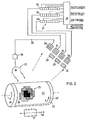
- FIG. 2 schematically shows a first exemplary embodiment of a monitoring device according to the present invention.
- the record carrier 22 is held on a suitable support, such as a rotating drum 23.
- the drum 23 is driven in the direction of the arrow 23 by conventional, controllable drive means (not shown).
- Part 25 of the reproduced image consists of a plurality of printed dots, which are shown as squares 26 for the sake of simplicity.
- Each of the printed dots is illuminated by a flash of white light from a stroboscope 27, and the light reflected by the recording medium 22, which has passed through the printing inks present on the relevant printed dot 26, is passed through a group of filters, namely magenta filters 28.
- a fourth light detector surface 34 is provided for scanning the spatial position of the overlying halftone patterns.
- the area 34 provides an output signal via a line 35 to a stroboscope control unit 36 which controls the flash frequency in order to keep the halftone patterns in the center of the detector areas 31 to 33.
- the output signals supplied by the surfaces 31 to 33 are fed to a delay network 37, which is composed of tapped shift registers 38, 39 and 40, the outputs of which are connected to a control unit 41, which in turn controls signals to the ink drop generator, i. H. supplies the piezoelectric crystal for the control of the drop frequency, to the pump for the control of the ink pressure, and to the deflection device, all for the correction of the ink jet in the y direction indicated by the arrow 42, and to the transport device of the ink jet print head, for the correction in the x direction indicated by arrow 43.
- a delay network 37 which is composed of tapped shift registers 38, 39 and 40, the outputs of which are connected to a control unit 41, which in turn controls signals to the ink drop generator, i. H. supplies the piezoelectric crystal for the control of the drop frequency, to the pump for the control of the ink pressure, and to the deflection device, all for the correction of the ink jet in the y direction indicated by the
- the stroboscope 27 is only switched on during the application of the second or following color. In this way the generation of a large output signal for the color printed first is avoided.
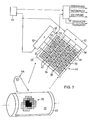
- Fig. 7 shows a further embodiment the optical device for detecting a positional deviation, in which the stroboscope 27 is replaced by a continuously white light-emitting light source 44, which can be an incandescent lamp, for example.
- the light reflected by the recording medium 22 and filtered by the printing ink printed thereon falls on an area scanner 45, which consists of an xy matrix - of light-sensitive elements 46, which are covered with filter masks 47 of different colors according to FIG. 7.
- the masks can consist of thin layers of colored film.
- the light-sensitive elements 46 can be designed, for example, as charge-coupled capacitors which store the light-generated charges.
- the capacitors 46 of each of the horizontal rows of arrays are connected to one of the common lines 48, 49, 50 and 51, which in turn are connected to a vertical (y) scan generator 52, while the capacitors 46 of each of the vertical columns of the array are connected to one of the common lines 53, 54, 55 and 56 are connected, which in turn are connected to a horizontal (x) scanning generator 57.
- the function of the stroboscope replaced in this exemplary embodiment is carried out by a pulsed lighting / reading circuit 59, which is controlled by a clock generator 60, which also controls the scan generators 52 and 57.
- the lighting / reading circuit 59 provides output signals for the control of the drop formation frequency, for the control of the ink pressure, for the control of the drop deflection device and for the control of the print head transport device on the basis of electronic sorting of the charge distribution for the second and following printed colors.
- the result of the scanning of the color printed first must be suppressed, which is done electronically in the embodiment described last.
Landscapes
- Engineering & Computer Science (AREA)
- Multimedia (AREA)
- Signal Processing (AREA)
- Quality & Reliability (AREA)
- Ink Jet (AREA)
- Facsimile Image Signal Circuits (AREA)
- Fax Reproducing Arrangements (AREA)
- Facsimile Transmission Control (AREA)
- Particle Formation And Scattering Control In Inkjet Printers (AREA)
Description
Die Erfindung betrifft ein Verfahren für die digitale Steuerung der Bildung von farbigen Wiedergaben für den Rasterdruck, sowie eine Vorrichtung zum Ausführen dieses Verfahrens. Unter « Rasterdruck » soll im Zusammenhang mit der vorliegenden Erfindung verstanden werden, dass ' eine endliche Anzahl von farbigen Halbton-Bildelementen gedruckt wird, wobei die Auswahl derart getroffen ist, dass das menschliche Auge aufgrund der ihm eigenen Auflösungsfähigkeit und seiner früheren Erfahrung beim Betrachten ähnlicher Bilder dazu tendiert getäuscht zu werden und so scheinbar ein Biid mit kontinuierlichem Farbübergang zu sehen und nicht ein gerastertes, d. h. « unterbrochenes » Farbbild.The invention relates to a method for digitally controlling the formation of colored reproductions for raster printing, and to an apparatus for carrying out this method. In the context of the present invention, “screen printing” is to be understood to mean that a finite number of colored halftone picture elements are printed, the selection being made in such a way that the human eye is more similar due to its own resolution capability and its previous experience in viewing Images tend to be deceived and thus seem to see a picture with a continuous color transition and not a rasterized, i.e. H. «Broken» color image.
Die Herstellung von SchwarzlWeiss-Bildern im Rasterdruck ist technisch einfach, und Drucker für diesen Zweck sind bekannt. Das Drucken von Farben ist jedoch weniger einfach, da es unmöglich ist, sämtliche Farbnuancen abzudrucken, zwischen denen das menschliche Auge unterscheiden kann. Man hat festgestellt, dass es für viele Zwecke vollkommen ausreichend ist, sieben Farben, einschliesslich Schwarz, (oder sogar weniger) abzudrucken, um ein Farbbild mit annehmbarer Qualität auf einem weissen Aufzeichnungsträger herzustellen, und dies, in dem man tatsächlich nur drei Farben abdruckt, was weiter hinten erläutert wird.The production of black and white images in raster printing is technically simple, and printers for this purpose are known. However, printing colors is less easy because it is impossible to reproduce all the shades of color that the human eye can distinguish between. It has been found that, for many purposes, it is entirely sufficient to print seven colors, including black, (or even less) to produce a color image of acceptable quality on a white recording medium, in which one actually prints only three colors, which will be explained later.
In der Drucktechnik ist seit langem bekannt, dass das menschliche Auge durch gewisse Moire-Muster irritiert wird, die in Rasterbildern auftreten, wenn die Raster der verschiedenen Farbauszüge nicht oder nicht genügend gegenüber der horizontalen Richtung gedreht sind. Im modernen Rasterdruck werden die verschiedenen Farbauszüge auch gegeneinander verdreht.It has long been known in printing technology that the human eye is irritated by certain moiré patterns which occur in raster images when the rasters of the different color separations are not or not sufficiently rotated with respect to the horizontal direction. In modern halftone printing, the different color separations are also twisted against each other.
Beim « Parallel •-Drüok werden alle Punkte des ganzen Bildes, die zu einem Farbauszug gehören, gleichzeitig gedruckt. Danach werden alle Punkte eines zweiten (oder weiteren) Farbauszuges gedruckt, wobei die Orientierung des Rasters der zweiten oder weiteren Farbe von der Orientierung des Rasters der ersten Farbe weggedreht wird. Dieses Verfahren erfordert natürlich die Herstellung so vieler Druckformen wie Farben (einschliesslich Schwarz) gedruckt werden sollen, und ebensoviele Durchgänge des Aufzeichungsträgers durch den Drucker. Die genaue Ausrichtung dieser Druckformen bietet jedoch keine wesentlichen Schwierigkeiten.With «Parallel • -Drüok, all dots of the whole picture that belong to a color separation are printed at the same time. All dots of a second (or further) color separation are then printed, the orientation of the grid of the second or further color being rotated away from the orientation of the grid of the first color. Of course, this process requires the production of as many printing forms as colors (including black) are to be printed, and as many passes of the recording medium through the printer. However, the exact alignment of these printing forms does not pose any major difficulties.
Beim « Serien »-Druck werden die Bildelemente sequentiell durch Uebereinanderdrucken der erforderlichen Farben in der Form von Punkten zusammengesetzt. Diese Punkte werden nebeneinander abgesetzt, so dass sie Druckzeilen bilden, und eine genügend grosse Anzahl von Druckzeilen wird untereinander angeordnet, um das ganze Bild zu bilden.With «series» printing, the picture elements are put together sequentially by printing the required colors in the form of dots. These dots are placed side by side so that they form print lines, and a sufficiently large number of print lines are arranged one below the other to form the whole image.
Wegen der Notwendigkeit, für jede zu druckende Farbe ein individuelles Raster herzustellen, ist das parallele Druckverfahren von Natur aus sehr langsam. Im Gegensatz dazu ist der serielle Druckprozess viel schneller, jedoch schwieriger. Für das serielle Druckverfahren gibt es im wesentlichen zwei Typen von Druckern. Der erste Typ ist der Aufschlag-Drucker, bei dem eine Spalte oder Matrix von Drähten in einem gemeinsamen Druckkopf angeordnet ist, die individuell betätigt werden können, um gegen ein Farbband gedrückt zu werden, welches seinerseits gegen den Aufzeichnungsträger gedrückt wird, um darauf einen Punkt zu erzeugen. Das Farbband ist als Vielfarben-Band ausgebildet und enthält die erforderliche Anzahl von Druckfarben und Schwarz. Ein Farbbandhubmechanismus ist für die Präsentation derjenigen Farbe an der Drahtmatrix des Druckkopfes verantwortlich, welche gedruckt oder übergedruckt werden soll. Wegen der Zeit, die die mechanischen Teile des Drahtdruckers zur Bewegung brauchen, insbesondere wegen der Rückkehrzeit des Hammers, sind diese Drucker immer noch ziemlich langsam. Der andere Druckertyp arbeitet mit flüssigen Tinten in verschiedenen Farben, die von einem gemeinsamen Druckkopf abgegeben werden, in welchem für jede Druckfarbe einschliesslich Schwarz eine eigene Düse vorgesehen ist. Diese Art Drucker ist die zur Zeit schnellste, insbesondere wegen der jetzt erhältlichen sehr schnell trocknenden Tinten.Because of the need to create an individual grid for each color to be printed, the parallel printing process is inherently very slow. In contrast, the serial printing process is much faster, but more difficult. There are essentially two types of printers for serial printing. The first type is the impact printer, in which a column or matrix of wires is arranged in a common printhead which can be individually operated to be pressed against an ink ribbon which in turn is pressed against the recording medium at a point thereon to create. The ribbon is designed as a multicolor ribbon and contains the required number of printing inks and black. A ribbon lift mechanism is responsible for presenting the color on the wire matrix of the print head that is to be printed or overprinted. Because of the time it takes for the mechanical parts of the wire printer to move, especially because of the hammer's return time, these printers are still quite slow. The other type of printer works with liquid inks in different colors, which are emitted by a common print head, in which a separate nozzle is provided for each printing ink, including black. This type of printer is currently the fastest, especially because of the very fast drying inks that are now available.
Wegen seiner Geschwindigkeit hat dieser Drucker die besten Voraussetzungen für die Benutzung in einer Farbbild-Wiedergabeanlage. Eine derartige Anlage kann entweder eine Farbkopiermaschine oder ein Farbbild-Faximile-Uebertragungssystem sein, was von dem Abstand zwischen Abtaster und Drukker abhängt. Obwohl die vorliegende Erfindung auch auf unabhängige Tintenstrahl-Drucker anwendbar ist, wird sie weiter unten am Beispiel eines Farbbild-Reproduktionssystems, nämlich einem Farbkopierer, beschrieben.Because of its speed, this printer has the best prerequisites for use in a color image display system. Such a system can either be a color copying machine or a color image faximile transmission system, which depends on the distance between the scanner and the printer. Although the present invention is also applicable to independent ink jet printers, it is described below using the example of a color image reproduction system, namely a color copier.
Zunächst soll kurz der konventionelle Farbbild-Reproduktionsprozess beschrieben werden. Das Farbbild-Original wird zunächst mittels eines Bandpassfilters in seine additiven Primärfarben Grün, Blau und Rot zerlegt, indem die Farb- « Amplitude », d. h. Farbintensität für alle Bildelemente in einen x-y-Raster des Originals gemessen wird. Dabei werden Intensitäten unterhalb eines gewissen Schwellenwertes vernachlässigt.First, the conventional color image reproduction process will be briefly described. The color image original is first broken down into its additive primary colors green, blue and red by means of a bandpass filter, in that the color “amplitude”, ie. H. Color intensity for all picture elements is measured in an x-y grid of the original. Intensities below a certain threshold are neglected.
Für die Rekonstruktion des Bildes auf einem weissen Aufzeichnungsträger werden die subtraktiven Primärfarben Magenta (absorbiert Grün), Gelb (absorbiert Blau) und Cyan (absorbiert Rot) benutzt. Die diesen subtraktiven Primärfarben entsprechenden Halbton-Muster müssen auf der Kopie in der gleichen x-y-Position wie im Original exakt übereinandergesetzt werden, doch muss das Raster der Farben gegenüber der Horizontalen gedreht werden. Dieses Erfordernis kann mit den konventionellen analogen oder digitalen Farbbild-Reproduktionstechniken, die gedrehte Raster verwenden, nicht erfüllt werden. Daher ist bei der konventionellen Farbwiedergabe die Wiedergabetreue mangelhaft und ihre Korrektur erfordert aufwendige und schwierig zu implementierende Massnahmen, um das Farbgleichgewicht herzustellen.The subtractive primary colors magenta (absorbs green), yellow (absorbs blue) and cyan (absorbs red) are used to reconstruct the image on a white recording medium. The halftone patterns corresponding to these subtractive primary colors must be exactly overlaid on the copy in the same xy position as in the original, but the grid of colors must be rotated with respect to the horizontal. This requirement can be met with the conventional analog or digital color image reproduction techniques that use rotated screens are not met. Therefore, the fidelity of conventional color reproduction is poor and its correction requires complex and difficult to implement measures to achieve the color balance.
Ein Verfahren zum Abtasten codierter Farbringe ist in der Schweizer Patentschrift 495.017 in Zusammenhang mit einem Verfahren zum Identifizieren von Ampullen, die pharmazeutische Produkte verschiedener Art enthalten, beschrieben. Die Ampullen tragen Ringe in den Farben Rot, Grün, Blau, Cyan, Magenta und Gelb. Der Abtaster benutzt dichroitische Spiegel um das von den Ringen reflektierte Licht in drei Spektralgebiete (Rot, Grün, Blau) aufzuteilen, und die von drei Photovervielfachern gelieferten und einen vorgegebenen Schwellenwert überschreitenden Farbsignale werden mittels eines selbsttaktierenden Systems digitalisiert. In dieser Patentschrift ist allerdings kein Rekonstruktionsmechanismus für die abgetastete Farbe gezeigt, d. h. ein Drucker ist nicht beschrieben.A method for scanning coded color rings is described in Swiss patent specification 495.017 in connection with a method for identifying ampoules which contain pharmaceutical products of various types. The ampoules have rings in the colors red, green, blue, cyan, magenta and yellow. The scanner uses dichroic mirrors to split the light reflected from the rings into three spectral regions (red, green, blue), and the color signals supplied by three photomultipliers and exceeding a predetermined threshold value are digitized using a self-clocking system. In this patent, however, no reconstruction mechanism for the scanned color is shown, i. H. a printer is not described.
Ein Tintenstrahl-Drucker mit drei Düsen für das Drucken von Rot, Gelb und Blau, die mit gegenseitigen Abständen von 120° um eine drehbare Trommel angeordnet sind, auf welcher der Aufzeichnungsträger fixiert ist, ist in der Schweizer Patentschrift 468.630 beschrieben, welche die Ausbildung von Ablenkelektroden für die Ablenkung der nicht zum Drucken benutzten Tropfen in eine Auffangvorrichtung lehrt. Das Problem fehlerhafter Farbbildüberlappungen wird hier überhaupt nicht discrutiert geschweige eine entsprechende Kompensationsschaltung beschrieben.An inkjet printer with three nozzles for printing red, yellow and blue, which are arranged at mutual intervals of 120 ° around a rotatable drum on which the recording medium is fixed, is described in Swiss Patent 468,630, which describes the formation of Deflection electrodes for deflecting the drops not used for printing into a collecting device teaches. The problem of incorrect color image overlaps is not discriminated here at all, let alone a corresponding compensation circuit.
Die Schweizer Patentschrift 537.757 betrifft einen Tintenstrahl-Drucker mit einem Druckkopf, der eine Vielzahl paralleler Düsen in linerarer oder Matrix-Anordnung aufweist. Die Patentschrift beschreibt die Ausbildung einer doppelten Zuführungskammer und erwähnt kurz die Ausrichtung der von verschiedenen parallelen Düsen abgegebenen Tropfen durch verzögerung der Betätigung der Düsen, so dass die Tropfen den Aufzeichnungsträger an der korrekten Stelle erreichen. Ausserdem wird die Möglichkeit erwähnt, verschiedene Farben zum Drukken zu verwenden, wobei die Farben sich entweder auf dem Aufzeichnungsträger mischen oder nebeneinander abgesetzt werden können.The Swiss patent 537.757 relates to an ink jet printer with a print head which has a plurality of parallel nozzles in a linear or matrix arrangement. The patent describes the formation of a double feed chamber and briefly mentions the alignment of the drops emitted by various parallel nozzles by delaying the actuation of the nozzles so that the drops reach the recording medium at the correct position. In addition, the possibility of using different colors for printing is mentioned, whereby the colors can either mix on the recording medium or be placed next to one another.
Aus den Patent Abstracts of Japan, Band II, Nr. 134 vom 9. November 1978 ist ein Verfahren zum digitalen Steuern der Bildung farbiger Wiedergaben mittels eines Tintenstrahl-Druckers ablesbar; das sämtliche Verfahrensschritte gemäss dem Oberbegriff des vorliegenden Anspruches 1 aufweist. Bei diesem bekannten Verfahren werden die Markierungen laufend mittels eines opto-elektrischen Abtasters abgetastet, der die zuletzt aufgebrachte Markierung abfühlt und mittels seines so gewonnenen Ausgangssignals den Tintenstrahl-Druckkopf neu aktiviert, um eine gegenüber der vorhergehenden Markierung innerhalb genauer Grenzen versetzte neue Markierung zu erhalten.From the Patent Abstracts of Japan, Volume II, No. 134 of November 9, 1978, a method for digitally controlling the formation of color reproductions by means of an ink jet printer can be read; which has all the method steps according to the preamble of the
Ein bei Seriendruckern mit Tintenstrahlen in verschiedenen Farben auftretendes ernstes Problem betrifft die örtliche Dilatation, die bei den meisten Aufzeichnungsträgern auftritt, wenn sie von Tintentropfen getroffen werden. Diese Dilatation macht es sehr schwierig, die folgenden Tintentropfen (der zweiten und weiteren Farben) an der gleichen Stelle präzise auszurichten. Da die Inhalte der zu reproduzierenden Bilder sehr stark variieren, gibt es keine Möglichkeit, die Dilatation durch geeignete mechanische Kompensationsmassnahmen zu antizipieren. Ferner variieren auch der Betrag und die Hauptrichtung der Dilatation in unvohersehbarer Weise, da sie von den vorherrschenden Umgebungsbedingungen und von Herstellungsparametern abhängen.A serious problem with serial printers with ink jets in different colors concerns the local dilation which occurs with most recording media when they are hit by ink drops. This dilation makes it very difficult to precisely align the following drops of ink (the second and further colors) in the same place. Since the contents of the images to be reproduced vary greatly, there is no way to anticipate the dilation by means of suitable mechanical compensation measures. Furthermore, the amount and the main direction of the dilatation also vary in an unforeseeable manner, since they depend on the prevailing environmental conditions and on production parameters.
Keine der dem Stand der Technik angehörenden Veröffentlichungen geht dieses Problem an, dessen Lösung jedoch von grosser Wichtigkeit für die Verbesserung der Druckqualität beim Farbdruck mit Tintenstrahl-Druckern ist. Es ist deshalb ein Hauptzweck der vorliegenden Erfindung, ein Verfahren für die digitale Farbbild-Wiedergabe anzugeben, welches die automatische Kompensation von Fehlausrichtungen des zweiten und der folgenden Tropfen mit dem zuerst gedruckten Tropfen gestattet, wenn diese Tropfen alle am gleichen Ort gedruckt werden sollen. Einzelheiten von Ausführungsbeispielen der Erfindung werden hiernach mit Bezug auf die beigefügten Zeichnungen beschrieben.
Figur 1 ist ein schematisches Blockschaltbild eines Farbbild-Wiedergabesystems ;Figur 2 ist ein Blockschaltbild einer erfindungsgemäßen Steuerschaltung für die Tintenstrahldüsen ;- Figur 3 zeigt Beispiele von korrekt ausgerichteten Druckfarben;
Figuren 4, 5 und 6 zeigen Druckfarben mit Fehlausrichtungen ;- Figur 7 zeigt ein weiteres Ausführungsbeispiel einer Steuerschaltung für die Tintenstrahldüsen.
- Figure 1 is a schematic block diagram of a color image display system;
- Figure 2 is a block diagram of a control circuit for the ink jet nozzles according to the invention;
- Figure 3 shows examples of correctly aligned printing inks;
- Figures 4, 5 and 6 show inks with misalignments;
- Figure 7 shows another embodiment of a control circuit for the ink jet nozzles.
Beim Vielfarbendruck mit Tintenstrahl-Druckern kommt entweder das « additive » oder « subtraktive Verfahren zur Anwendung, je nachdem welche Gruppe von Primärfarben benutzt wird. Beispielsweise wird in der oben erwähnten Schweizer Patentschrift 468.630 die Benutzung der additiven Primärfarben Rot, Gelb und Blau vorgeschlagen. Die vorliegende Erfindung bevorzugt die Benutzung der subtraktiven Primärfarben Magenta, Gelb und Cyan. Bekanntlich ergibt die Superposition von Magenta (welches Grün absorbiert) und Gelb (welches Blau absorbiert) Rot, die Superposition von Magenta und Cyan (welches Rot absorbiert) ergibt Blau, die Superposition Gelb und Cyan ergibt Grün, und die Superposition aller drei Farben ergibt Schwarz.Multi-color printing with inkjet printers uses either the "additive" or "subtractive" method, depending on which group of primary colors is used. For example, the use of the additive primary colors red, yellow and blue is proposed in the above-mentioned Swiss patent 468.630. The present invention prefers the use of the subtractive primary colors magenta, yellow and cyan. As is known, the superposition of magenta (which absorbs green) and yellow (which absorbs blue) results in red, the superposition of magenta and cyan (which absorbs red) gives blue, the superposition yellow and cyan gives green, and the superposition of all three colors gives black .
Daher ist es möglich, bei Benutzung von Magenta, Gelb und Cyan als Druckfarben Farbbilder zu rekonstruieren, welche neben diesen Druckfarben auch Rot, Blau, Grün und Schwarz, d. h. ein Total von sieben Farben enthalten. Dabei muss offensichtlich die Superposition der Druckfarben sehr exakt erfolgen, um eine Farbverschiebung oder das Auftreten eines unerwünschten Farbtons zu vermeiden.It is therefore possible to use color images when using magenta, yellow and cyan as printing inks to reconstruct which in addition to these printing colors also contain red, blue, green and black, ie a total of seven colors. Obviously, the superposition of the printing inks must be very precise in order to avoid a color shift or the occurrence of an undesirable color.
Man hat bereits seit langem beobachtet, dass Druckraster, deren Orientierung in der Leserichtung (oder orthogonal dazu) liegt, die Tendenz haben, Moire-Muster zu erzeugen, deren Frequenz meist sehr tief liegt, d. h. in einem Gebiet, in welchem das menschliche Auge am empfindlichsten ist. Daher benutzt die Druckindustrie unterschiedliche Drehwinkel für die einzelnen Farben, um die Frequenz der Moire-Muster zu erhöhen, so dass sie für das menschliche Auge weniger auffällig sind. Neuere Untersuchungen durch den Erfinder haben gezeigt, dass digitale Farbbilder mit gedrehten Rastern gegenüber mechanischen Ungenauigkeiten sehr resistent sind, und dass ein Moire-freies, farbtreues Bild mit guter Gesamtqualität auch dann erzeugt werden kann, wenn die subtraktiven Primärfarben Magenta, Gelb und Cyan alle unter dem gleichen Winkel von 45° orientiert sind.It has long been observed that print screens that are oriented in the reading direction (or orthogonal to it) tend to produce moiré patterns, the frequency of which is usually very low, i. H. in an area where the human eye is most sensitive. Therefore, the printing industry uses different rotation angles for the individual colors to increase the frequency of the moiré patterns so that they are less noticeable to the human eye. Recent investigations by the inventor have shown that digital color images with rotated screens are very resistant to mechanical inaccuracies, and that a moire-free, true-to-color image with good overall quality can be produced even if the subtractive primary colors magenta, yellow and cyan are all under are oriented at the same angle of 45 °.
Fig. 1 zeigt eine aus konventionellen Elementen aufgebaute Wiedergabevorrichtung, mit welcher die zu beschreibende Erfindung benutzt werden kann. Ein Original 1 wird von einer Lichtquelle 2 beleuchtet und mit einem Abtaster 3 abgetastet, dessen Abtastposition durch eine Steuereinheit 4 so gesteuert wird, dass er die Bildelemente des Originals 1 sequentiell abtastet. Das optische Ausgangssignal des Abtasters 3 wird nun im Sinne eines Bandpass-Filters in seine additiven Primärfarben Grün, Blau und Rot zerlegt, indem es durch dispersive Mittel geleitet wird, wie einen ersten dichroitischen Spiegel 5, welcher den Grünanteil ausscheidet, und einen zweiten dichroitischen Spiegel 6, welcher den Blauanteil aus dem Ausgangssignal des Abtasters ausscheidet.Fig. 1 shows a playback device constructed from conventional elements, with which the invention to be described can be used. An original 1 is illuminated by a
Die Grün- und Blauanteile, die durch die dichroitischen Spiegel 5 und 6 reflektiert werden, wie auch der Rotanteil, welcher durch beide Spiegel 5 und 6 hindurchgegangen ist, werden mittels den Farbkanälen individuell zugeordneten Photovervielfachern 7, 8 und 9 verstärkt. Die elektrischen Ausgangssignale der Photovervielfacher 7, 8 und 9 werden durch Schwellenschaltungen 10, 11 und 12 hindurchgeleitet. Diese werden durch einen gemeinsamen Taktgeber 13 getaktet, der auch mit der Positions-Steuereinheit 4 verbunden ist.The green and blue components, which are reflected by the
Die Ausgangssignale der Schwellenschaltungen 10, 11 und 12 stellen daher die digitalisierten Werte der Farbtönung der Grün-, Blau- und Rotanteile eines jeden Bildelements des Originals 1 dar. Für den Druck werden diese Farbtönungswerte der additiven Primärfarben zunächst in ihre äquivalenten Halbtonrepräsentationen umgesetzt. Der digitalisierte Farbtönungswert wird in eine angemessene Anzahl von Amplitudenwerten quantisiert und diese werden mit vorgegebenen Schwellenwerten verglichen, um binäre Ausgangssignale zu erzeugen, die angeben, ob die betreffende Farbe an der abgetasteten Stelle die Schwellenwerte überschreitet. Wie bereits erwähnt, muss bei der Farbwiedergabe das Raster der Bildelement-Matrix gegenüber der Horizontalen gedreht werden, damit kein unerwünschtes Moire-Muster entsteht. Der Algorithmus für die Erzeugung einer 45°-Drehung, wie im vorliegenden Fall, ist einfach und für den Fachmann naheliegend. Eine Anweisung zum digitalen Erzeugen von Drehungen irgendeiner Grösse hat der Erfinder im IBM Technical Dislocure Bulletin Band 20 Nr. 6, November 1977, Seiten 2423-2425 veröffentlicht.The output signals of the
Die resultierenden binären Ausgangssignale, welche für die Intensitäten der additiven Primärfarben repräsentativ sind, werden zur Steuerung von deren korrespondierenden subtraktiven Primärfarben benutzt, d. h. dass « Grün "-Signal steuert das Drucken von Magenta, das « Blau »-Signal steuert das Drucken von Gelb, das « Rot »-Signal steuert das Drucken von Cyan. Diese Steuerung erfolgt über konventionelle Druck-Steuereinheiten 14, 15 und 16, deren Ausgänge an einen Vielfarben-Tintenstrahl-Drucker 17 angeschlossen sind.The resulting binary output signals, which are representative of the intensities of the additive primary colors, are used to control their corresponding subtractive primary colors, ie the "green " signal controls the printing of magenta, the "blue" signal controls the printing of yellow, the “red” signal controls the printing of cyan, which is controlled by conventional
Der Drucker 17 weist alle Elemente auf, die im allgemeinen in jedem konventionellen Tintenstrahl-Drucker vorhanden sind, wie eine Tintenzuführungsvorrichtung mit Reservoir, Mittel zum Aufrechterhalten eines geeigneten Tintendrucks, Tropfenerzeugungs- und Ablenkmittel. Der Drucker 17 hat für jede Druckfarbe eine eigene Düse 18, 19, 20 und bei Bedarf eine zusätzliche Düse 21 für Schwarz zur Kontrastverbesserung.
Diese Düsen sind so ausgerichtet, dass die von ihnen abgegebenen Tropfen, die für die gleiche x, y Koordinate des zu rekonstruierenden Bildelementes vorgesehen ist, den Aufzeichnungsträger 22 zu verschiedenen Zeiten erreichen, wobei die dazwischenliegenden Zeitintervalle für das Trocknen der Tinte und den Transport des Aufzeichnungsträgers 22 benutzt werden. Der Drucker 17 und der (nicht gezeigte) Transportmechanismus für den Aufzeichungsträger 22 erhalten Steuersignale von der Steuereinheit 4, welche dafür sorgen, dass die Korrespondenz zwischen der x, y-Druckposition und der x, y-Abtastposition erhalten bleibt.These nozzles are oriented so that the drops they dispense, which are intended for the same x, y coordinate of the picture element to be reconstructed, reach the
Natürlich kann diese Steuerung nicht diejenigen Abweichungen der Druckposition bewältigen, die durch das Nasswerden des Aufzeichnungsträgers beim Abdrucken der ersten Farbe entstehen, und die in einer kleinen Dilatation und damit Verschiebung der Tropfen der zweiten (und dritten) Farbe von der wirklichen Druckposition, resultieren, wodurch eine Farbverschiebung oder eine Verfärbung in einer oder mehreren Farben auftritt.Of course, this control cannot cope with the deviations in the printing position which result from the wet-out of the recording medium when the first color is printed and which result in a small dilatation and thus displacement of the drops of the second (and third) color from the actual printing position, as a result of which a color shift or discoloration occurs in one or more colors.
Die Erfindung lehrt daher die laufende Ueberwachung des Abdrucks am Aufzeichnungsträger und die Entwicklung eines geeigneten Korrektursignals, mit dem die Stellung des Druckers 17 bezüglich des Aufzeichnungsträger 22 korrigiert werden kann und zur Beeinflussung der Abgabezeiten der zweiten und dritten Druckfarbe.The invention therefore teaches the continuous monitoring of the impression on the recording medium and the development of a suitable correction signal with which the position of the
Fig. 2 zeigt schematisch ein erstes Ausführungsbeispiel einer Ueberwachungseinrichtung gemäss der vorliegenden Erfindung. Der Aufzeichnungsträger 22 ist auf einem geeigneten Support gehalten, wie beispielsweise einer rotierenden Trommel 23. Die Trommel 23 wird durch konventionelle, steuerbare Antriebsmittel (nicht gezeigt) in Richtung des Pfeils 23 angetrieben. Ein Teil 25 des wiedergegebenen Bildes besteht aus einer Vielzahl von gedruckten Punkten, die der Einfachheit halber als Quadrate 26 dargestellt sind. Jeder der gedruckten Punkte wird durch einen Blitz weissen Lichts von einen Stroboskop 27 beleuchtet, und das vom Aufzeichnungsträger 22 reflektierte Licht, welches die auf dem betreffenden gedruckten Punkt 26 vorhandenen Druckfarben passiert hat, wird durch eine Gruppe von Filtern, nämlich Magenta-Filter 28, Gelb-Filter 29 und Cyan-Filter 30, auf einen zweidimensionalen Lichtdetektor geworfen, der beispielsweise die ladungsgekoppelten flächenhaften Vorrichtungen 31, 32 und 33 umfassen kann. Diese transformieren die empfangenen Spektralanteile in elektrische Signale.2 schematically shows a first exemplary embodiment of a monitoring device according to the present invention. The
Eine vierte Lichtdetektor-Fläche 34 ist für die Abtastung der räumlichen Position der übereinanderliegenden Halbton-Muster vorgesehen. Die Fläche 34 liefert ein Ausgangssignal über eine Leitung 35 an eine Stroboskop-Steuereinheit 36, welche die Blitzfrequenz steuert, um die Halbton-Muster im Zentrum der Detektorflächen 31 bis 33 zu halten.A fourth
Die von den Flächen 31 bis 33 gelieferten Ausgangssignale werden einem Verzögerungsnetzwerk 37 zugeführt, welches aus angezapften Schieberegistern 38, 39 und 40 aufgebaut ist, deren Ausgänge an eine Steuereinheit 41 angeschlossen sind, welche ihrerseits Steuersignale an den Tintentropfen-Generator, d. h. den piezoelektrischen Kristall für die Steuerung der Tropfenfrequenz, an die Pumpe für die Steuerung des Tintendrucks, und an die Ablenkvorrichtung liefert, alles für die Korrektur des Tintenstrahls in der durch den Pfeil 42 bezeichneten y-Richtung, und an die Transportvorrichtung des Tintenstrahl-Druckkopfes, für die Korrektur in der durch den Pfeil 43 bezeichneten x-Richtung.The output signals supplied by the
Die Fign. 3 bis 6 zeigen Beispiele für die Farb-(Fehl-) Ausrichtung und die Korrekturstrategie. In Fig. 3 liegen die Farben jeweils in Superposition, und obwohl die von den einzelnen Farben eingenommenen Flächen teilweise unterschiedliche Grösse aufweisen, ist keine Korrektur erforderlich. Fig. 4 zeigt eine Situation, in welcher zwei Farben gegeneinander versetzt sind, in Fig. 5 sind zwei Farben miteinander ausgerichtet während eine dritte fehlausgerichtet ist, und Fig. 6 zeigt alle drei Farben gegeneinander versetzt. Natürlich ist in den Fällen der Fign. 4 bis 6 eine Korrektur erforderlich. Beim Drucken mit den subtraktiven Primärfarben Gelb, Magenta und Cyan, in dieser Reihenfolge, können die folgenden Fälle auftreten :
- 1. Falls nur eine der Farben zu drucken ist, fällt Licht nur durch das dieser Farbe zugeordnete
Filter den zugehörigen Lichtdetektor 31, 32 oder 33. Die Intensität des Lichts ist in diesem Fall ein Maximum. Es muss jedoch von der Steuereinheit 41 kein Korrektursignal erzeugt werden, da keine Fehlausrichtung einer Farbe bezüglich einer andern aufgetreten ist. - 2. Falls zwei Farben zu drucken sind, können sie entweder miteinander ausgerichtet (Fig. 3) oder fehlausgerichtet (Fig. 4) sein. Im ersteren Fall kann kein Licht eins der
Filter 28bis 30 passieren, da eine der Farben überhaupt nicht vorkommt und die beiden andern sich zu Rot, Grün oder Blau mischen, wofür alle Filter undurchlässig sind. Im Fall der Fehlausrichtung der beiden Farben fällt durch die ihnen zugeordneten Filter Licht geringer Intensität, und die zugehörigen Lichtdetektoren 31, 32 oder 33 werden Ausgangssignale abgeben, aus denen dieSteuereinheit 41 Korrektursignale erzeugt. - 3. Im Fall des Druckes aller drei Farben können drei Situationen auftreten, nämlich a) alle drei Farben sind miteinander ausgerichtet, b) zwei der Farben sind miteinander ausgerichtet und die dritte ist bezüglich der Ersteren fehlausgerichtet (Fig. 5), oder c) zwei Farben sind bezüglich der zuerst gedruckten Farbe je fehlausgerichtet (Fig. 6), und ferner sind sie untereinander fehlausgerichtet.
- a) Genaue Ausrichtung aller drei Farben ergibt Schwarz, ein Ausgangssignal wird nicht erzeugt.
- b) Die beiden miteinander ausgerichteten Farben mischen sich zu einer neuen Farbe (Rot, oder Grün, oder Blau), für welche alle Filter undurchlässig sind. An der Stelle, an welcher alle drei Farben sich überdecken, ergibt sich Schwarz. Daher wird nur das Filter der fehlausgerichteten Farbe ein kleines Ausgangssignal liefern.
- c) Wenn alle drei Farben gegenseitig fehlausgerichtet sind, ergibt sich eine schwarze Zone, die kein Ausgangssignal erzeugt, und es gibt drei Zonen mit neuen Farben (Rot, Grün, Blau), die von den Filtern gesperrt werden, und es gibt drei kleine Ausgangssignale, die von den Stellen herrühren, an welchen sich die Druckfarben nicht überdecken.
- 1. If only one of the colors is to be printed, light falls only through the
filter light detector 31, 32 or 33. The intensity of the light is a maximum in this case . However, no correction signal has to be generated by thecontrol unit 41 since no misalignment of one color with another has occurred. - 2. If two colors are to be printed, they can either be aligned (Fig. 3) or misaligned (Fig. 4). In the former case, no light can pass through one of the
filters 28 to 30, since one of the colors does not occur at all and the other two mix to form red, green or blue, for which all filters are opaque. In the event of misalignment of the two colors, low-intensity light falls through the filters assigned to them, and the associatedlight detectors 31, 32 or 33 emit output signals from which thecontrol unit 41 generates correction signals. - 3. In the case of printing all three colors, three situations can arise, namely a) all three colors are aligned, b) two of the colors are aligned and the third is misaligned with respect to the former (Fig. 5), or c) two Colors are each misaligned with respect to the color printed first (Fig. 6) and further misaligned with each other.
- a) Precise alignment of all three colors results in black, an output signal is not generated.
- b) The two aligned colors mix into a new color (red, or green, or blue), for which all filters are impermeable. At the point where all three colors overlap, there is black. Therefore, only the misaligned color filter will provide a small output.
- c) If all three colors are mutually misaligned, there is a black zone that produces no output signal, and there are three zones with new colors (red, green, blue) that are blocked by the filters, and there are three small output signals that arise from the places where the printing inks do not overlap.
Daraus ergibt sich, dass entweder ein grosses Ausgangssignal für eine allein zu druckende Farbe vorhanden sein kann oder ein kleines Ausgangssignal, das durch eine fehlausgerichtete Farbe verursacht wird. Um die Position einer als zweite oder folgende gedruckten Farbe bezüglich der zuerst gedruckten zu korrigieren, wird das Stroboskop 27 nur während des Auftrags der zweiten oder folgenden Farbe eingeschaltet. Auf diese Weise wird die Erzeugung eines grossen Ausgangssignals für die zuerst gedruckte Farbe vermieden.As a result, there can be either a large output signal for a color to be printed alone or a small output signal caused by a misaligned color. In order to correct the position of a color printed as the second or following color with respect to the color printed first, the
Fig. 7 zeigt ein weiteres Ausführungsbeispiel der optischen Einrichtung zum Erkennen einer Positionsabweichung, worin das Stroboskop 27 durch eine dauernd weisses Licht abgebende Lichtquelle 44 ersetzt ist, die beispielsweise eine Glühlampe sein kann. Das vom Aufzeichnungsträger 22 reflektierte und durch die auf diesen gedruckte Druckfarbe gefilterte Licht fällt auf einen Flächenabtaster 45, welcher aus einer x-y-Matrix - von lichtempfindlichen Elementen 46 besteht, die mit Filtermasken 47 verschiedener Farben gemäss Fig. 7 bedeckt sind. Die Masken können aus dünnen Schichten farbigen Films bestehen. Die lichtempfindlichen Elemente 46 können beispielsweise als ladungsgekoppelte Kondensatoren ausgebildet sein, welche die lichterzeugten Ladungen speichern. Die Kondensatoren 46 jeder der horizontalen Matrixreihen sind an eine der gemeinsamen Leitungen 48, 49, 50 und 51 angeschlossen, welche ihrerseits an einen Vertikal-(y)-Abtastgenerator 52 angeschlossen sind, während die Kondensatoren 46 jeder der vertikalen Spalten der Matrix an eine der gemeinsamen Leitungen 53, 54, 55 und 56 angeschlossen sind, die ihrerseits mit einem Horizontal-(x)-Abtastgenerator 57 verbunden sind.Fig. 7 shows a further embodiment the optical device for detecting a positional deviation, in which the
Falls Impulse von den Vertikal- und Horizontal-Abtastgeneratoren 52 und 57 in der geeigneten Reihenfolge an einem x,y-Matrixpunkt koinzidieren, wird"die zuvor an diesem Punkt gespeicherte integrierte photoelektrische Ladung in ein Substrat 58 abgeleitet, auf dem die Kondensatoren 46 angeordnet sind, und ein entsprechender Videostrom wird aus dieser Ladung erzeugt. In dem Buch von C.H. Sequin, M.F. Tompsett, « Charge Transfer Devices, Advances in Electronics and Electron Physics, Academic Press, New York 1975 *, sind weitere Ladungstransfer-Vorrichtungen beschrieben.If pulses from the vertical and
Die Funktion des in diesem Ausführungsbeispiel ersetzten Stroboskops wird durch eine gepulste Beleuchtungs-/Leseschaltung 59 ausgeführt, die von einem Taktgeber 60 gesteuert wird, der auch die Abtastgeneratoren 52 und 57 steuert. Die Beleuchtungs-/Leseschaltung 59 liefert Ausgangssignale für die Steuerung der Tropfenbildungsfrequenz, für die Steuerung des Tintendrucks, für die Steuerung der Tropfenablenkvorrichtung und für die Steuerung der Druckkopftransportvorrichtung auf der Basis elektronischer Sortierung der Ladungsverteilung für die als zweite und folgende gedruckten Farben. Wie im Ausführungsbeispiel mit dem Stroboskop muss das Resultat der Abtastung der zuerst gedruckten Farbe unterdrückt werden, was in dem zuletzt beschriebenen Ausführungsbeispiel auf elektronische Weise geschieht.The function of the stroboscope replaced in this exemplary embodiment is carried out by a pulsed lighting /
Claims (4)
Applications Claiming Priority (2)
| Application Number | Priority Date | Filing Date | Title |
|---|---|---|---|
| CH12213/78 | 1978-11-29 | ||
| CH1221378A CH637331A5 (en) | 1978-11-29 | 1978-11-29 | METHOD AND DEVICE FOR DIGITALLY CONTROLLING THE FORMATION OF COLORED REPRODUCTIONS. |
Publications (3)
| Publication Number | Publication Date |
|---|---|
| EP0011722A2 EP0011722A2 (en) | 1980-06-11 |
| EP0011722A3 EP0011722A3 (en) | 1981-01-21 |
| EP0011722B1 true EP0011722B1 (en) | 1983-05-11 |
Family
ID=4380946
Family Applications (1)
| Application Number | Title | Priority Date | Filing Date |
|---|---|---|---|
| EP79104229A Expired EP0011722B1 (en) | 1978-11-29 | 1979-10-31 | Process and device for the digital control of the making of colour reproductions |
Country Status (6)
| Country | Link |
|---|---|
| EP (1) | EP0011722B1 (en) |
| JP (1) | JPS5574884A (en) |
| CA (1) | CA1138521A (en) |
| CH (1) | CH637331A5 (en) |
| DE (1) | DE2965397D1 (en) |
| IT (1) | IT1165338B (en) |
Cited By (2)
| Publication number | Priority date | Publication date | Assignee | Title |
|---|---|---|---|---|
| DE3333801A1 (en) * | 1982-09-20 | 1984-03-22 | Sony Corp., Tokyo | COLOR SIGNAL PROCESSING CIRCUIT |
| DE3802736A1 (en) * | 1987-01-29 | 1988-08-18 | Toshiba Kk | Image generating device (picture generating device) |
Families Citing this family (18)
| Publication number | Priority date | Publication date | Assignee | Title |
|---|---|---|---|---|
| US4403874A (en) * | 1980-03-25 | 1983-09-13 | Ramtek Corporation | Color printer and multi-ribbon cartridge therefor |
| JPS572163A (en) * | 1980-06-06 | 1982-01-07 | Canon Inc | Multicolor ink jet recording device |
| JPS5741966A (en) * | 1980-08-26 | 1982-03-09 | Canon Inc | Color ink jet recording device |
| JPS5741965A (en) * | 1980-08-26 | 1982-03-09 | Canon Inc | Color ink jet recording device |
| JPS5741967A (en) * | 1980-08-26 | 1982-03-09 | Canon Inc | Color ink jet recording device |
| JPS57100580A (en) * | 1980-12-15 | 1982-06-22 | Fuji Photo Film Co Ltd | Ink jet printer |
| JPH0666881B2 (en) * | 1981-09-18 | 1994-08-24 | キヤノン株式会社 | Color image processing device |
| DE3408336A1 (en) * | 1983-03-08 | 1984-09-13 | Canon K.K., Tokio/Tokyo | IMAGE REPRODUCTION SYSTEM |
| US4683492A (en) * | 1983-03-08 | 1987-07-28 | Canon Kabushiki Kaisha | Method and apparatus for recording a full-color image with a plurality of colorants on the basis of a set of area factors for the colorants selected from a plurality of sets of area factors calculated from a plurality of sets of equations |
| US5191361A (en) * | 1983-03-08 | 1993-03-02 | Canon Kabushiki Kaisha | Image reproducing system |
| DE3526133A1 (en) * | 1985-07-22 | 1987-01-29 | Hell Rudolf Dr Ing Gmbh | Method for producing colour pictures |
| US4853768A (en) * | 1985-12-26 | 1989-08-01 | Canon Kabushiki Kaisha | Color image processing apparatus with linear masking circuit having coefficients which vary in accordance with the levels of color component signals |
| JP2840323B2 (en) * | 1989-09-28 | 1998-12-24 | キヤノン株式会社 | Color image recording device |
| NL9400355A (en) * | 1994-03-07 | 1995-10-02 | Stork Colorproofing | Method for registering color division images and pattern of images obtained therewith. |
| JP2840584B2 (en) * | 1996-02-28 | 1998-12-24 | キヤノン株式会社 | Image forming device |
| ES2120914B1 (en) | 1997-02-05 | 1999-06-01 | Carrasco Martinez Vicente | METHOD FOR PRINTING IN POLYCHROMIA ON VARIOUS SURFACES. |
| GB2379414A (en) | 2001-09-10 | 2003-03-12 | Seiko Epson Corp | Method of forming a large flexible electronic display on a substrate using an inkjet head(s) disposed about a vacuum roller holding the substrate |
| US8383840B1 (en) | 2005-06-15 | 2013-02-26 | Geoff McMahon | Extraction of fulvic minerals, vitamins, amino acids, enzymes, and phytonutrients from humic substances |
Family Cites Families (5)
| Publication number | Priority date | Publication date | Assignee | Title |
|---|---|---|---|---|
| CH495017A (en) * | 1968-07-16 | 1970-08-15 | Ciba Geigy | Method for scanning color codes and converting them into binary codes, as well as means for carrying out this method |
| JPS5648869B2 (en) * | 1972-12-22 | 1981-11-18 | ||
| JPS53102036A (en) * | 1977-02-17 | 1978-09-06 | Sanyo Electric Co Ltd | Ink jet printer |
| JPS5829740B2 (en) * | 1977-06-06 | 1983-06-24 | 株式会社リコー | Color inkjet recording device |
| JPS54104342A (en) * | 1978-02-01 | 1979-08-16 | Ricoh Co Ltd | Color ink jet transfer printer |
-
1978
- 1978-11-29 CH CH1221378A patent/CH637331A5/en not_active IP Right Cessation
-
1979
- 1979-10-16 CA CA000337706A patent/CA1138521A/en not_active Expired
- 1979-10-31 EP EP79104229A patent/EP0011722B1/en not_active Expired
- 1979-10-31 DE DE7979104229T patent/DE2965397D1/en not_active Expired
- 1979-10-31 IT IT26959/79A patent/IT1165338B/en active
- 1979-11-16 JP JP14787379A patent/JPS5574884A/en active Granted
Cited By (2)
| Publication number | Priority date | Publication date | Assignee | Title |
|---|---|---|---|---|
| DE3333801A1 (en) * | 1982-09-20 | 1984-03-22 | Sony Corp., Tokyo | COLOR SIGNAL PROCESSING CIRCUIT |
| DE3802736A1 (en) * | 1987-01-29 | 1988-08-18 | Toshiba Kk | Image generating device (picture generating device) |
Also Published As
| Publication number | Publication date |
|---|---|
| JPS5574884A (en) | 1980-06-05 |
| CH637331A5 (en) | 1983-07-29 |
| EP0011722A2 (en) | 1980-06-11 |
| DE2965397D1 (en) | 1983-06-16 |
| CA1138521A (en) | 1982-12-28 |
| EP0011722A3 (en) | 1981-01-21 |
| IT1165338B (en) | 1987-04-22 |
| JPS6226620B2 (en) | 1987-06-10 |
| IT7926959A0 (en) | 1979-10-31 |
Similar Documents
| Publication | Publication Date | Title |
|---|---|---|
| EP0011722B1 (en) | Process and device for the digital control of the making of colour reproductions | |
| DE3143562C2 (en) | ||
| DE69228030T2 (en) | Ink jet recording process | |
| DE2262824C3 (en) | Process for the rasterized reproduction of colored halftone images in single or multi-color printing | |
| DE69011319T2 (en) | BIDIRECTIONAL COLOR JET PRINTING WITH HOT-MELTING INK. | |
| DE3688715T4 (en) | Scanning record type printing method and its realization device. | |
| DE60025582T2 (en) | Printer with simplified manufacturing process and manufacturing process | |
| DE69320144T2 (en) | Apparatus and method for producing halftone color images | |
| DE3215276C2 (en) | Inkjet printer | |
| DE2321689C3 (en) | Color scanner | |
| DE69016473T2 (en) | Color video printer. | |
| DE2817641A1 (en) | INKJET PRINTER | |
| DE2556565B2 (en) | METHOD AND DEVICE FOR GENERATING PSEUDO HALFTONE PATTERNS | |
| DE3043101C2 (en) | ||
| DE68908122T2 (en) | Method and device for producing a multicolored image. | |
| DE3338868A1 (en) | IMAGE PROCESSING DEVICE | |
| EP0131145B1 (en) | Multicolour printing with seven or eight printing colours and with adjacent surface elements | |
| DE2012728C3 (en) | Process for the electro-optical recording of screened halftone images | |
| EP0019270B1 (en) | Multicolour print and process for the manufacture of the printing forms for this print | |
| DE69112323T2 (en) | Ink drop positioning for image construction. | |
| DE60129996T2 (en) | PRINTING ON THE FRONT LAYER OF A DATA RECORDING MEDIUM | |
| DE69619727T2 (en) | Print images using a dot matrix printer | |
| DE2101862C2 (en) | Device for creating color separations from several templates | |
| CH568593A5 (en) | Colour printing device with selective point exposures - uses sensitive layer and four colour electrostatic system | |
| DE2646925B2 (en) | Process for obtaining digital recording data for screened color separations |
Legal Events
| Date | Code | Title | Description |
|---|---|---|---|
| PUAI | Public reference made under article 153(3) epc to a published international application that has entered the european phase |
Free format text: ORIGINAL CODE: 0009012 |
|
| AK | Designated contracting states |
Designated state(s): DE FR GB |
|
| PUAL | Search report despatched |
Free format text: ORIGINAL CODE: 0009013 |
|
| AK | Designated contracting states | ||
| RHK1 | Main classification (correction) |
Ipc: B41J 3/04 |
|
| 17P | Request for examination filed |
Effective date: 19810205 |
|
| GRAA | (expected) grant |
Free format text: ORIGINAL CODE: 0009210 |
|
| AK | Designated contracting states |
Designated state(s): DE FR GB |
|
| REF | Corresponds to: |
Ref document number: 2965397 Country of ref document: DE Date of ref document: 19830616 |
|
| ET | Fr: translation filed | ||
| PLBE | No opposition filed within time limit |
Free format text: ORIGINAL CODE: 0009261 |
|
| STAA | Information on the status of an ep patent application or granted ep patent |
Free format text: STATUS: NO OPPOSITION FILED WITHIN TIME LIMIT |
|
| 26N | No opposition filed | ||
| PGFP | Annual fee paid to national office [announced via postgrant information from national office to epo] |
Ref country code: FR Payment date: 19890927 Year of fee payment: 11 |
|
| PGFP | Annual fee paid to national office [announced via postgrant information from national office to epo] |
Ref country code: GB Payment date: 19890930 Year of fee payment: 11 |
|
| PGFP | Annual fee paid to national office [announced via postgrant information from national office to epo] |
Ref country code: DE Payment date: 19891111 Year of fee payment: 11 |
|
| PG25 | Lapsed in a contracting state [announced via postgrant information from national office to epo] |
Ref country code: GB Effective date: 19901031 |
|
| GBPC | Gb: european patent ceased through non-payment of renewal fee | ||
| PG25 | Lapsed in a contracting state [announced via postgrant information from national office to epo] |
Ref country code: FR Effective date: 19910628 |
|
| PG25 | Lapsed in a contracting state [announced via postgrant information from national office to epo] |
Ref country code: DE Effective date: 19910702 |
|
| REG | Reference to a national code |
Ref country code: FR Ref legal event code: ST |