EP0011681A1 - Baromètre - Google Patents
Baromètre Download PDFInfo
- Publication number
- EP0011681A1 EP0011681A1 EP79102923A EP79102923A EP0011681A1 EP 0011681 A1 EP0011681 A1 EP 0011681A1 EP 79102923 A EP79102923 A EP 79102923A EP 79102923 A EP79102923 A EP 79102923A EP 0011681 A1 EP0011681 A1 EP 0011681A1
- Authority
- EP
- European Patent Office
- Prior art keywords
- lever arm
- lever
- membrane capsule
- shaft
- barometer
- Prior art date
- Legal status (The legal status is an assumption and is not a legal conclusion. Google has not performed a legal analysis and makes no representation as to the accuracy of the status listed.)
- Granted
Links
Images
Classifications
-
- G—PHYSICS
- G01—MEASURING; TESTING
- G01L—MEASURING FORCE, STRESS, TORQUE, WORK, MECHANICAL POWER, MECHANICAL EFFICIENCY, OR FLUID PRESSURE
- G01L7/00—Measuring the steady or quasi-steady pressure of a fluid or a fluent solid material by mechanical or fluid pressure-sensitive elements
- G01L7/02—Measuring the steady or quasi-steady pressure of a fluid or a fluent solid material by mechanical or fluid pressure-sensitive elements in the form of elastically-deformable gauges
- G01L7/10—Measuring the steady or quasi-steady pressure of a fluid or a fluent solid material by mechanical or fluid pressure-sensitive elements in the form of elastically-deformable gauges of the capsule type
- G01L7/12—Measuring the steady or quasi-steady pressure of a fluid or a fluent solid material by mechanical or fluid pressure-sensitive elements in the form of elastically-deformable gauges of the capsule type with exhausted chamber; Aneroid barometers
- G01L7/14—Measuring the steady or quasi-steady pressure of a fluid or a fluent solid material by mechanical or fluid pressure-sensitive elements in the form of elastically-deformable gauges of the capsule type with exhausted chamber; Aneroid barometers with zero-setting means
-
- G—PHYSICS
- G01—MEASURING; TESTING
- G01D—MEASURING NOT SPECIALLY ADAPTED FOR A SPECIFIC VARIABLE; ARRANGEMENTS FOR MEASURING TWO OR MORE VARIABLES NOT COVERED IN A SINGLE OTHER SUBCLASS; TARIFF METERING APPARATUS; MEASURING OR TESTING NOT OTHERWISE PROVIDED FOR
- G01D5/00—Mechanical means for transferring the output of a sensing member; Means for converting the output of a sensing member to another variable where the form or nature of the sensing member does not constrain the means for converting; Transducers not specially adapted for a specific variable
- G01D5/02—Mechanical means for transferring the output of a sensing member; Means for converting the output of a sensing member to another variable where the form or nature of the sensing member does not constrain the means for converting; Transducers not specially adapted for a specific variable using mechanical means
- G01D5/04—Mechanical means for transferring the output of a sensing member; Means for converting the output of a sensing member to another variable where the form or nature of the sensing member does not constrain the means for converting; Transducers not specially adapted for a specific variable using mechanical means using levers; using cams; using gearing
-
- G—PHYSICS
- G01—MEASURING; TESTING
- G01L—MEASURING FORCE, STRESS, TORQUE, WORK, MECHANICAL POWER, MECHANICAL EFFICIENCY, OR FLUID PRESSURE
- G01L7/00—Measuring the steady or quasi-steady pressure of a fluid or a fluent solid material by mechanical or fluid pressure-sensitive elements
- G01L7/02—Measuring the steady or quasi-steady pressure of a fluid or a fluent solid material by mechanical or fluid pressure-sensitive elements in the form of elastically-deformable gauges
- G01L7/10—Measuring the steady or quasi-steady pressure of a fluid or a fluent solid material by mechanical or fluid pressure-sensitive elements in the form of elastically-deformable gauges of the capsule type
- G01L7/104—Measuring the steady or quasi-steady pressure of a fluid or a fluent solid material by mechanical or fluid pressure-sensitive elements in the form of elastically-deformable gauges of the capsule type with mechanical transmitting or indicating means
Definitions
- the invention relates to a barometer according to the preamble of claim 1. Such a barometer is known.
- the membrane capsule which consists of two metal membranes connected gastight at the edge, is completely evacuated. Appropriate preloading of the metal membranes ensures that the metal membranes are not pressed against one another by the surrounding air pressure, but are at a greater or lesser distance from one another depending on the level of the air pressure.
- a membrane capsule is called a stabilized membrane capsule, in contrast to known non-stabilized membrane capsules, in which the metal membranes are pulled apart by an additional support spring.
- the transmission mechanism comprises a two-armed lever which is pivotably articulated on the base plate and which engages with its long lever arm on the second lever arm of the lever shaft which is mounted on the base plate and on the first lever arm of which a chain which forms the drive element of the pointer mechanism is fastened the pointer shaft is laid.
- the plate of the pointer mechanism facing the membrane capsule has an extension which extends over the edge of the plate and is fastened to the base plate by means of a stud bolt.
- pointer mechanisms with a chain or a thread
- pointer mechanisms with a pinion on the pointer shaft and a tooth segment meshing therewith are known, with which the first pointer arm of the pointer shaft is engaged.
- a disadvantage of the known barometer on which the preamble of claim 1 is based is that the transmission unit requires considerable manufacturing and assembly work and also requires a large amount of space.
- the reason plate have a significantly larger diameter than the membrane capsule so that the base plate can carry the pivotable two-armed lever and the lever shaft.
- the transmission work consisting of numerous elements cannot be prefabricated as a unit; rather, the elements pointer mechanism, two-armed lever and lever shaft must be attached separately to the base plate.
- Another disadvantage of the known barometer is that, due to the high frictional resistance in the transmission, small changes in air pressure are not displayed automatically.
- the invention has for its object to design a generic barometer such that its transmission mechanism requires less manufacturing and assembly. Furthermore, the space requirement of the barometer to be created should be small, however, the greatest possible pointer travel should be ensured given the deflection of the membrane capsule. Finally, the frictional resistances in the transmission unit should be kept so low that even slight changes in atmospheric pressure are displayed.
- the object is achieved in that the free end of the second lever arm of the lever shaft rests directly on the membrane capsule and that the axis of the second lever arm extends obliquely to the plane of the membrane capsule.
- the pivotable two-armed lever - or the lever on the support spring of an unstabilized diaphragm capsule - is not required, so that its manufacturing and assembly costs as well as space and movement resistance are eliminated.
- the inclination of the axis of the second lever arm ensures that the transmission ratio is not smaller despite the absence of the two-armed lever, because when the angle between the axis of the second lever arm and the plane of the membrane capsule - hereinafter referred to as the support angle - is, for example, 60 °, for a given deflection of the membrane capsule, a rotation angle of the lever shaft that is twice as large as in the case of a parallel arrangement of the second lever arm and membrane is effected capsule level. In other words this means that the inclination of 60 ° has the same effect as with a two-armed lever that has a lever arm ratio of 2: 1.
- the term "axis of the second lever arm” is understood here to mean the solder from its free end resting on the axis of rotation of the lever shaft.
- the contact angle is therefore preferably in the range from 40 ° to 70 °, more preferably in the range from 45 ° to 60 °.
- the second lever arm is provided with an external thread and is adjustably screwed into the lever shaft. This enables a very simple adjustment and adjustment of the length of the second lever arm and thus of the support angle and the transmission ratio of the transmission unit.
- the arrangement of the second lever arm according to the invention is particularly advantageously effected in that the lever shaft, which carries the second lever arm, is supported with its two ends on the first circuit board facing the membrane capsule, and preferably in its plane.
- the result is d a - thanks to a particularly compact transmission unit that can be prefabricated as a unit and attached to the base plate. Since this complete transfer mechanism is arranged on one side of the membrane capsule, the base plate need not protrude radially beyond the membrane capsule.
- the drive element of the pointer mechanism of the barometer according to the invention can be both a thread or a chain and a tooth segment. If a tooth segment is used, this is preferably stored in the two plates of the pointer mechanism, so that the existing components are used optimally.
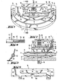
- a barometer is shown in FIG. 1, but its housing, lens, dial and pointer have been omitted.
- the barometer shown comprises a circular base plate 2 which carries a likewise circular membrane capsule 4 concentrically.
- the membrane capsule 4 consists of an upper metal membrane 6 in FIGS. 1 and 2 and a lower metal membrane 8, which are connected airtightly at their edges, and is partially evacuated.
- the two metal membranes 6 and 8 have such a prestress that the membrane capsule does not require a support spring to stabilize it, i.e. is stabilized.
- a threaded pin 10 (see FIG. 2) is fastened in the middle, which is screwed into a threaded hole in the base plate 2 and allows a slot at its free end for the engagement of a suitable tool, so that the distance between the membrane capsule 4 can be changed or adjusted by the base plate 2 by turning the threaded pin 10 and thus the membrane capsule 4.
- a circular support plate 12 (see FIG. 2) with a smooth surface is fastened in the middle of the upper metal membrane 6.
- the transfer device of the barometer is arranged on one side of the membrane capsule 4, namely the side of the upper metal membrane 6.
- the transmission unit comprises a first circuit board 14 facing the upper metal membrane 6 and a second circuit board 16 arranged at a distance from and parallel to the first circuit board.
- the two circuit boards are firmly connected to one another by stud bolts 18 and 20.
- the first place t ine 14 is fastened at its ends to lugs 22 and 24 of the base plate 2 by means of screws (not shown) in such a way that the base plate alone carries the entire transmission system next to the membrane capsule 4 by means of these lugs,
- a pointer shaft 26 is rotatably mounted, on which a pinion 28 is fastened between the two boards, which alternatively can be formed in one piece with the pointer shaft.
- a spiral spring 30, which is fixed to the stud bolt 18, engages on the pointer shaft.
- a toothed segment 32 meshes with the pinion 28, which preferably has an internal toothing and whose segment shaft 34 is rotatably mounted in the two plates 14 and 16.
- the two boards 14 and 16, the stud bolts 18 and 20, the pointer shaft 26, the pinion 28, the spiral spring 30 and the toothed segment 32 with its segment shaft 34 form the pointer mechanism of the transmission mechanism shown.
- a pointer (not shown) can be plugged onto the pointer shaft 26.
- the first board 14 has on one of its long sides two lugs 36 and 38 at a certain distance from one another.
- a lever shaft 40 is rotatably mounted such that the lever shaft 40 extends in the plane of the first board 14, as can be seen from Figures 1 and 2.
- its two bearings are designed as tip bearings, for which purpose a bearing screw 42 which is conical at its free end and which engages in a corresponding bore at one end of the lever shaft 40 is screwed into the extension 36.
- a conical tip is formed which, together with a bore in the shoulder 38, forms the other tip bearing.
- the lever shaft 40 carries at its right end in FIG. 1 a first lever arm 44 which passes through a slot 46 in the tooth segment 32 extends so that the toothed segment 32 is pivoted by rotating the lever shaft 40 and thus the pointer mechanism is driven.
- the distance between the point of engagement between the first lever arm 44 and the toothed segment 32 on the one hand and the segment shaft 34 of the toothed segment 32 on the other hand is as small as possible in relation to the pitch circle radius of the toothed segment 32 so that a large transmission ratio of the transmission mechanism is achieved.
- the first lever arm 44 is designed as a straight pin.
- the lever shaft 40 carries a second lever arm 48 which, in the exemplary embodiment shown in FIGS. 1 and 2, is designed as a cylinder head screw which is screwed into a corresponding threaded hole in the lever shaft 40 and tapers sharply at its free end.
- the pointer shaft 26, the membrane capsule 4 and the base plate 2 are arranged concentrically to one another in the exemplary embodiment shown.
- the second lever arm 48 sits on the lever shaft 40 such that the axis A of the second lever arm 48 forms a right angle with the axis of rotation of the lever shaft 40 and is directed obliquely downward (in FIG. 2) to the center of the membrane capsule 4.
- the free end of the lever arm 48 lies directly on the support plate, and the axis A includes a support angle a with the plane B defined in the exemplary embodiment shown by the joint between the two metal membranes 6 and 8 (see FIG. 2).
- An angle ⁇ is included between the axis C of the first lever arm 44 and the plane of movement of the toothed segment 32, which coincides with the toothed segment. It can be seen from FIG. 2 that when the contact angle a becomes smaller, the angle ⁇ also becomes smaller and vice versa.
- the entire transmission unit is a compact unit consisting of a few elements, which as a whole can be prefabricated and connected to the base plate 2 and takes up little space. All elements of the transmission mechanism - with the exception of the circuit boards 14 and 16 themselves - are carried by the two circuit boards of the pointer mechanism.
- the second lever arm 48 is pivoted clockwise (in FIG. 2), as a result of which the lever shaft 40 rotates clockwise and thereby the first lever arm 44 in turn is pivoted clockwise.
- the contact angle a is in the range from 40 ° to 70 °, preferably in the range from .45 ° to 60 °, the deflection of the upper metal membrane 6 causes a relatively large angle of rotation of the lever shaft 40. In any case, this angle of rotation is given the deflection of the upper metal membrane or the membrane capsule is much larger than if axis A were to run approximately parallel to plane B.
- the contact angle a is relatively small in the range mentioned, so that a given deflection is associated with a smaller angle of rotation of the lever shaft 40, the angle ⁇ is also smaller, so that again a given angle of rotation of the lever shaft 40 has a greater movement distance at the point of engagement is assigned between the first lever arm 44 and the toothed segment 32, as a result of which the reduction in the transmission ratio is compensated for by the smaller contact angle a.
- the pivoting of the first lever arm 44 in turn has the consequence that the toothed segment 32 around its S egmentwelle 34 is rotated so that the pinion 28 meshing with the toothed segment 32 and thereby in turn the pointer shaft 26 is rotated.
- FIG. 3 to 5 show modifications of the exemplary embodiment described above.
- Figure 3 shows in a representation similar to Figure 2 only the lever shaft 40 and the second lever arm 48.
- the second lever arm 48 is not designed as an adjustable screw but as a cylindrical pin with a pointed free end. It is also essential in this modification that. the second lever arm 48 rests with its free end directly on the membrane capsule and that the axis of the second lever arm 48 extends obliquely to the plane of the membrane capsule.
- FIG. 4 shows a detail of a modification of the right end of the lever shaft 40 in FIG. 1 with the associated bearing. In the modification according to FIG. 4, this bearing is not designed as a tip bearing.
- a cylindrical bore 52 is provided in the projection 38, in which a compression spring 54 is seated and into which a cylindrical extension 56 of the lever shaft 40 is inserted.
- the compression spring 54 is supported at one end on the extension 56, so that a force directed toward the left (in FIG. 4) is exerted on the lever shaft 40.
- the lever shaft 40 is adjustably mounted in the axial direction, since the extension 56 protrudes more or less into the bore 52 by adjusting the bearing screw 42. This adjustment allows a simple change in the transmission ratio of the transmission system, since the distance between the point of engagement between the first lever arm 44 and the toothed segment 32 on the one hand and the segment shaft 34 on the other hand is changed by the axial displacement of the lever shaft 40.
- FIG. 1 a modified first circuit board 14 is shown in FIG.
- the first circuit board 14 need not be formed in one piece. Much more it can be constructed from several elements, for example circuit board elements 14a and 14b, which are only firmly connected to one another by the stud bolts 18 and 20.
- the board element 14b has the shape of the second board 16 according to FIG. 1
- the board element 14a has the shape of the first board 14 according to FIG. 1.
- the modified embodiment of the first board 14 according to FIG with regard to the formation of the journal bearings for the pointer shaft 26 and the segment shaft 34.
Landscapes
- Physics & Mathematics (AREA)
- General Physics & Mathematics (AREA)
- Measuring Fluid Pressure (AREA)
- Details Of Measuring And Other Instruments (AREA)
- Measuring Pulse, Heart Rate, Blood Pressure Or Blood Flow (AREA)
- Sewing Machines And Sewing (AREA)
Priority Applications (1)
| Application Number | Priority Date | Filing Date | Title |
|---|---|---|---|
| AT79102923T ATE2577T1 (de) | 1978-11-28 | 1979-08-13 | Barometer. |
Applications Claiming Priority (2)
| Application Number | Priority Date | Filing Date | Title |
|---|---|---|---|
| DE19782851359 DE2851359A1 (de) | 1978-11-28 | 1978-11-28 | Barometer |
| DE2851359 | 1978-11-28 |
Publications (2)
| Publication Number | Publication Date |
|---|---|
| EP0011681A1 true EP0011681A1 (fr) | 1980-06-11 |
| EP0011681B1 EP0011681B1 (fr) | 1983-02-16 |
Family
ID=6055710
Family Applications (1)
| Application Number | Title | Priority Date | Filing Date |
|---|---|---|---|
| EP79102923A Expired EP0011681B1 (fr) | 1978-11-28 | 1979-08-13 | Baromètre |
Country Status (6)
| Country | Link |
|---|---|
| US (1) | US4238958A (fr) |
| EP (1) | EP0011681B1 (fr) |
| JP (1) | JPS5572837A (fr) |
| AT (1) | ATE2577T1 (fr) |
| BR (1) | BR7906219A (fr) |
| DE (1) | DE2851359A1 (fr) |
Cited By (3)
| Publication number | Priority date | Publication date | Assignee | Title |
|---|---|---|---|---|
| EP0053195A1 (fr) * | 1980-11-28 | 1982-06-09 | Helmut Bernhardt GmbH u. Co. KG Feinmechanik | Dispositif de mesure à aiguilles |
| EP3136071A1 (fr) * | 2015-08-25 | 2017-03-01 | The Swatch Group Research and Development Ltd. | Dispositif et procede d'etalonnage d'un dispositif de mesure de l'altitude |
| EP3136073A1 (fr) * | 2015-08-25 | 2017-03-01 | The Swatch Group Research and Development Ltd. | Dispositif de mesure de l'altitude et objet portable comprenant un tel dispositif |
Families Citing this family (4)
| Publication number | Priority date | Publication date | Assignee | Title |
|---|---|---|---|---|
| DE2940969C2 (de) * | 1979-10-09 | 1982-12-02 | Helmut Bernhardt Gmbh & Co Kg, 8354 Metten | Zeigermeßwerk |
| DE3022210A1 (de) * | 1980-06-13 | 1981-12-24 | Alexander Wiegand Gmbh U. Co Armaturen- U. Manometerfabrik, 8763 Klingenberg | Absolutdruckmanometer |
| FR2633043B1 (fr) * | 1988-06-17 | 1990-10-26 | Altitude Sa | Mecanisme de barometre aneroide |
| US7350414B1 (en) | 2004-05-11 | 2008-04-01 | Trintec Industries, Inc. | Mechanical barometer |
Citations (6)
| Publication number | Priority date | Publication date | Assignee | Title |
|---|---|---|---|---|
| US1647342A (en) * | 1924-11-22 | 1927-11-01 | Grolan Mfg Company | Diaphragm pressure gauge |
| US2035025A (en) * | 1933-03-30 | 1936-03-24 | Doherty Res Co | Pressure gauge |
| FR831614A (fr) * | 1937-01-05 | 1938-09-09 | I S S A Ind Specializzata Stru | Anémomètre à correction d'altitude |
| GB538849A (en) * | 1940-02-16 | 1941-08-19 | Korect Depth Gauge Company Ltd | Improvements in or relating to pressure gauges |
| FR2209093A1 (fr) * | 1972-12-01 | 1974-06-28 | Parmentier Jean | |
| DE2263373A1 (de) * | 1972-12-23 | 1974-07-11 | Georg Fritz Fa | Druckmessgeraet mit einstellbarer uebersetzung |
Family Cites Families (8)
| Publication number | Priority date | Publication date | Assignee | Title |
|---|---|---|---|---|
| US2560237A (en) * | 1951-07-10 | Sphygmomanometer | ||
| US1891134A (en) * | 1929-12-31 | 1932-12-13 | Aircraft Control Corp | Indicating apparatus |
| DE636548C (de) * | 1933-08-08 | 1936-10-10 | Henri Gody | Barometer mit Tendenzanzeiger |
| US2194624A (en) * | 1937-05-21 | 1940-03-26 | Bendix Aviat Corp | Diaphragm pressure gauge having temperature compensating means |
| US2235110A (en) * | 1937-07-14 | 1941-03-18 | Bendix Aviat Corp | Temperature compensated pressure responsive indicating instrument |
| US2689480A (en) * | 1950-04-15 | 1954-09-21 | Kollsman Instr Corp | Sensitive wide range altimeter |
| US2691305A (en) * | 1952-05-17 | 1954-10-12 | Lackner Company Inc | Barometric altimeter |
| JPS5316362U (fr) * | 1976-07-23 | 1978-02-10 |
-
1978
- 1978-11-28 DE DE19782851359 patent/DE2851359A1/de active Granted
-
1979
- 1979-08-13 EP EP79102923A patent/EP0011681B1/fr not_active Expired
- 1979-08-13 AT AT79102923T patent/ATE2577T1/de active
- 1979-09-28 BR BR7906219A patent/BR7906219A/pt not_active IP Right Cessation
- 1979-10-04 US US06/081,994 patent/US4238958A/en not_active Expired - Lifetime
- 1979-10-16 JP JP13346679A patent/JPS5572837A/ja active Pending
Patent Citations (6)
| Publication number | Priority date | Publication date | Assignee | Title |
|---|---|---|---|---|
| US1647342A (en) * | 1924-11-22 | 1927-11-01 | Grolan Mfg Company | Diaphragm pressure gauge |
| US2035025A (en) * | 1933-03-30 | 1936-03-24 | Doherty Res Co | Pressure gauge |
| FR831614A (fr) * | 1937-01-05 | 1938-09-09 | I S S A Ind Specializzata Stru | Anémomètre à correction d'altitude |
| GB538849A (en) * | 1940-02-16 | 1941-08-19 | Korect Depth Gauge Company Ltd | Improvements in or relating to pressure gauges |
| FR2209093A1 (fr) * | 1972-12-01 | 1974-06-28 | Parmentier Jean | |
| DE2263373A1 (de) * | 1972-12-23 | 1974-07-11 | Georg Fritz Fa | Druckmessgeraet mit einstellbarer uebersetzung |
Cited By (6)
| Publication number | Priority date | Publication date | Assignee | Title |
|---|---|---|---|---|
| EP0053195A1 (fr) * | 1980-11-28 | 1982-06-09 | Helmut Bernhardt GmbH u. Co. KG Feinmechanik | Dispositif de mesure à aiguilles |
| EP3136071A1 (fr) * | 2015-08-25 | 2017-03-01 | The Swatch Group Research and Development Ltd. | Dispositif et procede d'etalonnage d'un dispositif de mesure de l'altitude |
| EP3136073A1 (fr) * | 2015-08-25 | 2017-03-01 | The Swatch Group Research and Development Ltd. | Dispositif de mesure de l'altitude et objet portable comprenant un tel dispositif |
| EP3136072A1 (fr) * | 2015-08-25 | 2017-03-01 | The Swatch Group Research and Development Ltd. | Dispositif de mesure de l'altitude et objet portable comprenant un tel dispositif |
| US9995592B2 (en) | 2015-08-25 | 2018-06-12 | The Swatch Group Research And Development Ltd | Device and method for calibrating an altitude measurement device |
| US10295344B2 (en) | 2015-08-25 | 2019-05-21 | The Swatch Group Research And Development Ltd | Altitude measurement device and portable object comprising the same |
Also Published As
| Publication number | Publication date |
|---|---|
| JPS5572837A (en) | 1980-06-02 |
| DE2851359C2 (fr) | 1987-01-08 |
| DE2851359A1 (de) | 1980-06-04 |
| EP0011681B1 (fr) | 1983-02-16 |
| BR7906219A (pt) | 1980-07-15 |
| ATE2577T1 (de) | 1983-03-15 |
| US4238958A (en) | 1980-12-16 |
Similar Documents
| Publication | Publication Date | Title |
|---|---|---|
| DE3610284A1 (de) | Antriebsmechanismus mit einer gewindespindel und spindelmutter | |
| DE2521942C3 (de) | Betätigungsvorrichtung für eine Armatur mit drehbarem Verschlußstück | |
| EP0126273B1 (fr) | Baromètre | |
| DE3321050C2 (fr) | ||
| EP0011681B1 (fr) | Baromètre | |
| DE3221011A1 (de) | Walze | |
| EP0683931B1 (fr) | Appareil de commande et/ou de signalisation | |
| DE3332483A1 (de) | Zahnstangenlenkung | |
| DE2621675A1 (de) | Untersetzungsvorrichtung zum oeffnen und schliessen eines ventils | |
| DE2638981C3 (de) | Hilfskraftlenkung, insbesondere für Kraftfahrzeuge | |
| DE2415814B2 (de) | Kondensator veränderlicher Kapazität | |
| DE2308287B2 (de) | Vorrichtung zur Drehwinkeleinstellung eines Werkstückes | |
| DE2601308B2 (de) | Fernverstellbarer Außenrückblickspiegel für Fahrzeuge, insbesondere Kraftfahrzeuge | |
| DE7815650U1 (de) | Einrastvorrichtung fuer einstellscheiben | |
| DE3714637A1 (de) | Drehmoment-ausgleichssystem | |
| DE7835226U1 (de) | Barometer | |
| DE3007571A1 (de) | Schnellverstellzirkel | |
| DE1299485B (de) | Bohrkopf | |
| AT408529B (de) | Positioniervorrichtung für einen schweissbrenner | |
| DE2055063C3 (fr) | ||
| DE2403578A1 (de) | Vorrichtung zum beseitigen des toten spiels | |
| DE1564621C3 (de) | Abgleichbarer Schalenkern für Spulen der Nachrichtentechnik | |
| DE1298817B (de) | Zweiteiliges, in der Laenge mittels einer Verstellmutter einstellbares Kurbelgestaenge | |
| DE2024734C3 (de) | Faltenbalgaggregat | |
| EP4379492A1 (fr) | Régulateur de débit volumique |
Legal Events
| Date | Code | Title | Description |
|---|---|---|---|
| PUAI | Public reference made under article 153(3) epc to a published international application that has entered the european phase |
Free format text: ORIGINAL CODE: 0009012 |
|
| AK | Designated contracting states |
Designated state(s): AT BE CH FR GB IT LU NL |
|
| ITCL | It: translation for ep claims filed |
Representative=s name: INGG. GUZZI RAVIZZA |
|
| 17P | Request for examination filed |
Effective date: 19801211 |
|
| ITF | It: translation for a ep patent filed |
Owner name: GUZZI E RAVIZZA S.R.L. |
|
| GRAA | (expected) grant |
Free format text: ORIGINAL CODE: 0009210 |
|
| AK | Designated contracting states |
Designated state(s): AT BE CH FR GB IT LU NL |
|
| REF | Corresponds to: |
Ref document number: 2577 Country of ref document: AT Date of ref document: 19830315 Kind code of ref document: T |
|
| ET | Fr: translation filed | ||
| ITTA | It: last paid annual fee | ||
| EPTA | Lu: last paid annual fee | ||
| PGFP | Annual fee paid to national office [announced via postgrant information from national office to epo] |
Ref country code: AT Payment date: 19960822 Year of fee payment: 18 |
|
| PG25 | Lapsed in a contracting state [announced via postgrant information from national office to epo] |
Ref country code: AT Free format text: LAPSE BECAUSE OF NON-PAYMENT OF DUE FEES Effective date: 19970813 |
|
| PGFP | Annual fee paid to national office [announced via postgrant information from national office to epo] |
Ref country code: GB Payment date: 19980720 Year of fee payment: 20 Ref country code: FR Payment date: 19980720 Year of fee payment: 20 |
|
| PGFP | Annual fee paid to national office [announced via postgrant information from national office to epo] |
Ref country code: CH Payment date: 19980825 Year of fee payment: 20 Ref country code: BE Payment date: 19980825 Year of fee payment: 20 |
|
| PGFP | Annual fee paid to national office [announced via postgrant information from national office to epo] |
Ref country code: NL Payment date: 19980827 Year of fee payment: 20 |
|
| PGFP | Annual fee paid to national office [announced via postgrant information from national office to epo] |
Ref country code: LU Payment date: 19980902 Year of fee payment: 20 |
|
| BE20 | Be: patent expired |
Free format text: 19990813 *DOSTMANN G.M.B.H. & CO. K.G. |
|
| PG25 | Lapsed in a contracting state [announced via postgrant information from national office to epo] |
Ref country code: GB Free format text: LAPSE BECAUSE OF NON-PAYMENT OF DUE FEES Effective date: 19990812 Ref country code: CH Free format text: LAPSE BECAUSE OF EXPIRATION OF PROTECTION Effective date: 19990812 |
|
| PG25 | Lapsed in a contracting state [announced via postgrant information from national office to epo] |
Ref country code: NL Free format text: LAPSE BECAUSE OF EXPIRATION OF PROTECTION Effective date: 19990813 Ref country code: LU Free format text: LAPSE BECAUSE OF EXPIRATION OF PROTECTION Effective date: 19990813 |
|
| REG | Reference to a national code |
Ref country code: GB Ref legal event code: PE20 Effective date: 19990812 |
|
| REG | Reference to a national code |
Ref country code: CH Ref legal event code: PL |
|
| PLBE | No opposition filed within time limit |
Free format text: ORIGINAL CODE: 0009261 |
|
| STAA | Information on the status of an ep patent application or granted ep patent |
Free format text: STATUS: NO OPPOSITION FILED WITHIN TIME LIMIT |