EP0011550A1 - Process and machine for covering a tubular element, notably for covering a box - Google Patents
Process and machine for covering a tubular element, notably for covering a box Download PDFInfo
- Publication number
- EP0011550A1 EP0011550A1 EP79400832A EP79400832A EP0011550A1 EP 0011550 A1 EP0011550 A1 EP 0011550A1 EP 79400832 A EP79400832 A EP 79400832A EP 79400832 A EP79400832 A EP 79400832A EP 0011550 A1 EP0011550 A1 EP 0011550A1
- Authority
- EP
- European Patent Office
- Prior art keywords
- mandrel
- tubular element
- station
- machine according
- plate
- Prior art date
- Legal status (The legal status is an assumption and is not a legal conclusion. Google has not performed a legal analysis and makes no representation as to the accuracy of the status listed.)
- Withdrawn
Links
Images


Classifications
-
- B—PERFORMING OPERATIONS; TRANSPORTING
- B31—MAKING ARTICLES OF PAPER, CARDBOARD OR MATERIAL WORKED IN A MANNER ANALOGOUS TO PAPER; WORKING PAPER, CARDBOARD OR MATERIAL WORKED IN A MANNER ANALOGOUS TO PAPER
- B31B—MAKING CONTAINERS OF PAPER, CARDBOARD OR MATERIAL WORKED IN A MANNER ANALOGOUS TO PAPER
- B31B70/00—Making flexible containers, e.g. envelopes or bags
-
- B—PERFORMING OPERATIONS; TRANSPORTING
- B31—MAKING ARTICLES OF PAPER, CARDBOARD OR MATERIAL WORKED IN A MANNER ANALOGOUS TO PAPER; WORKING PAPER, CARDBOARD OR MATERIAL WORKED IN A MANNER ANALOGOUS TO PAPER
- B31B—MAKING CONTAINERS OF PAPER, CARDBOARD OR MATERIAL WORKED IN A MANNER ANALOGOUS TO PAPER
- B31B50/00—Making rigid or semi-rigid containers, e.g. boxes or cartons
- B31B50/02—Feeding or positioning sheets, blanks or webs
- B31B50/022—Holders for feeding or positioning blanks or webs
- B31B50/024—Rotating holders, e.g. star wheels, drums
-
- B—PERFORMING OPERATIONS; TRANSPORTING
- B31—MAKING ARTICLES OF PAPER, CARDBOARD OR MATERIAL WORKED IN A MANNER ANALOGOUS TO PAPER; WORKING PAPER, CARDBOARD OR MATERIAL WORKED IN A MANNER ANALOGOUS TO PAPER
- B31B—MAKING CONTAINERS OF PAPER, CARDBOARD OR MATERIAL WORKED IN A MANNER ANALOGOUS TO PAPER
- B31B2105/00—Rigid or semi-rigid containers made by assembling separate sheets, blanks or webs
-
- B—PERFORMING OPERATIONS; TRANSPORTING
- B31—MAKING ARTICLES OF PAPER, CARDBOARD OR MATERIAL WORKED IN A MANNER ANALOGOUS TO PAPER; WORKING PAPER, CARDBOARD OR MATERIAL WORKED IN A MANNER ANALOGOUS TO PAPER
- B31B—MAKING CONTAINERS OF PAPER, CARDBOARD OR MATERIAL WORKED IN A MANNER ANALOGOUS TO PAPER
- B31B2110/00—Shape of rigid or semi-rigid containers
- B31B2110/30—Shape of rigid or semi-rigid containers having a polygonal cross section
- B31B2110/35—Shape of rigid or semi-rigid containers having a polygonal cross section rectangular, e.g. square
-
- B—PERFORMING OPERATIONS; TRANSPORTING
- B31—MAKING ARTICLES OF PAPER, CARDBOARD OR MATERIAL WORKED IN A MANNER ANALOGOUS TO PAPER; WORKING PAPER, CARDBOARD OR MATERIAL WORKED IN A MANNER ANALOGOUS TO PAPER
- B31B—MAKING CONTAINERS OF PAPER, CARDBOARD OR MATERIAL WORKED IN A MANNER ANALOGOUS TO PAPER
- B31B2120/00—Construction of rigid or semi-rigid containers
- B31B2120/50—Construction of rigid or semi-rigid containers covered or externally reinforced
- B31B2120/501—Construction of rigid or semi-rigid containers covered or externally reinforced by applying wrapping material only on the side wall part of a box
-
- B—PERFORMING OPERATIONS; TRANSPORTING
- B31—MAKING ARTICLES OF PAPER, CARDBOARD OR MATERIAL WORKED IN A MANNER ANALOGOUS TO PAPER; WORKING PAPER, CARDBOARD OR MATERIAL WORKED IN A MANNER ANALOGOUS TO PAPER
- B31B—MAKING CONTAINERS OF PAPER, CARDBOARD OR MATERIAL WORKED IN A MANNER ANALOGOUS TO PAPER
- B31B2160/00—Shape of flexible containers
- B31B2160/10—Shape of flexible containers rectangular and flat, i.e. without structural provision for thickness of contents
-
- B—PERFORMING OPERATIONS; TRANSPORTING
- B31—MAKING ARTICLES OF PAPER, CARDBOARD OR MATERIAL WORKED IN A MANNER ANALOGOUS TO PAPER; WORKING PAPER, CARDBOARD OR MATERIAL WORKED IN A MANNER ANALOGOUS TO PAPER
- B31B—MAKING CONTAINERS OF PAPER, CARDBOARD OR MATERIAL WORKED IN A MANNER ANALOGOUS TO PAPER
- B31B50/00—Making rigid or semi-rigid containers, e.g. boxes or cartons
- B31B50/26—Folding sheets, blanks or webs
- B31B50/28—Folding sheets, blanks or webs around mandrels, e.g. for forming bottoms
- B31B50/30—Folding sheets, blanks or webs around mandrels, e.g. for forming bottoms the mandrels moving
- B31B50/32—Folding sheets, blanks or webs around mandrels, e.g. for forming bottoms the mandrels moving in circular paths
- B31B50/324—Folding sheets, blanks or webs around mandrels, e.g. for forming bottoms the mandrels moving in circular paths the mandrels being parallel to the axis of a drum
-
- B—PERFORMING OPERATIONS; TRANSPORTING
- B31—MAKING ARTICLES OF PAPER, CARDBOARD OR MATERIAL WORKED IN A MANNER ANALOGOUS TO PAPER; WORKING PAPER, CARDBOARD OR MATERIAL WORKED IN A MANNER ANALOGOUS TO PAPER
- B31B—MAKING CONTAINERS OF PAPER, CARDBOARD OR MATERIAL WORKED IN A MANNER ANALOGOUS TO PAPER
- B31B50/00—Making rigid or semi-rigid containers, e.g. boxes or cartons
- B31B50/26—Folding sheets, blanks or webs
- B31B50/28—Folding sheets, blanks or webs around mandrels, e.g. for forming bottoms
- B31B50/30—Folding sheets, blanks or webs around mandrels, e.g. for forming bottoms the mandrels moving
- B31B50/34—Folding sheets, blanks or webs around mandrels, e.g. for forming bottoms the mandrels moving about their own axes
-
- Y—GENERAL TAGGING OF NEW TECHNOLOGICAL DEVELOPMENTS; GENERAL TAGGING OF CROSS-SECTIONAL TECHNOLOGIES SPANNING OVER SEVERAL SECTIONS OF THE IPC; TECHNICAL SUBJECTS COVERED BY FORMER USPC CROSS-REFERENCE ART COLLECTIONS [XRACs] AND DIGESTS
- Y10—TECHNICAL SUBJECTS COVERED BY FORMER USPC
- Y10T—TECHNICAL SUBJECTS COVERED BY FORMER US CLASSIFICATION
- Y10T156/00—Adhesive bonding and miscellaneous chemical manufacture
- Y10T156/10—Methods of surface bonding and/or assembly therefor
- Y10T156/1002—Methods of surface bonding and/or assembly therefor with permanent bending or reshaping or surface deformation of self sustaining lamina
- Y10T156/1028—Methods of surface bonding and/or assembly therefor with permanent bending or reshaping or surface deformation of self sustaining lamina by bending, drawing or stretch forming sheet to assume shape of configured lamina while in contact therewith
- Y10T156/103—Encasing or enveloping the configured lamina
Definitions
- the present invention relates to a method and to a machine for covering a tubular element, in particular for covering a box, more particularly for covering with a sheet of paper or other material, boxes, called bell boxes, made of cardboard. , used for packaging in perfumery and all other applications, said tubular element being able to have any section, round, oval, square, polygonal with sharp or rounded angles, etc. and to have any desired height, long or short.
- This machine covering applies in practice only to rectangular boxes of a relatively reduced height compared to the dimensions of the base and having sharp edges.
- Such a machine does not allow the covering of the bell boxes which are therefore generally dressed by hand.
- the subject of the present invention is a method for covering a tubular element of any section and of any height, large or small, allowing automatic dressing. on machine.
- a method for covering a tubular element is characterized in that one starts from a portion of adhering covering strip, the length of which is slightly greater than the perimeter of the tubular element and the width of which is slightly greater than the height of the tubular element, said tubular element is applied to a median part of the strip portion, leaving at least one projecting protrusion, said tubular element is thus partially applied and adhered to said portion on a mandrel strip, said strip portion is wound around the tubular element engaged on the mandrel, in that for this winding, the lateral parts of the strip portion are raised on either side of the tubular element making adhere with protruding above the tubular element and is exerted on the protruding side parts raised folding actions to bring them and make them adhere, with a slight rec openly, on the tubular element engaged on the mandrel, in that said protruding overhang of the strip portion is folded opposite an open end of the tubular element engaged on the mandrel and in that it is recessed this projecting
- the present invention also relates to a machine for dressing a tubular element whose construction is particularly simple and robust and allows to dress a plurality of tubular elements with a high rate, ensuring the operations of winding and recessing and also , if necessary, other operations that are still useful for dressing purposes, for example the folding down of a second projecting over a closed end of the tubular element opposite the open end, and this d 'an integrity manner, that is to say without any puffy parts or creases.
- a machine for dressing a tubular element comprises a fixed frame, a plate mounted rotating on said frame around a general axis, said frame having a plurality of fixed stations for winding d 'a portion of covering strip adhering around the tubular element and for a recess of a protrusion of said strip portion in an open end of said tubular element, said turntable having a plurality of pins parallel to said general axis, each spindle integrally carrying a mandrel of the same section as the tubular element and, in an angularly integral manner and free in translation, a cap of the same section as the mandrel, control means in.
- the machine turns with a pilgrim step to successively bring each spindle to the different stations.
- the tubular element which has been partially applied and adhered to the strip portion is engaged on the mandrel which is therein, placing this tubular member in such a way that the strip portion is located upstream side in the direction of rotation of the machine table.
- fixed application members preferably brushes provided with a plastic coating
- a mobile application member for example formed by a brush provided with a plastic coating, sweeps the protruding one of the side parts raised to bring it and make it adhere to the tubular element.
- another mobile application member similar to the previous one and preferably formed by a brush provided with a plastic coating, sweeps beyond the other raised side part to fold it down and make it adhere with a slight overlap on the first protruding folded down and adhered to the second post.
- FIG. 1 to 23 relates, by way of non-limiting example, an application of the invention to a machine for dressing a tubular element of cardboard or other material in the form of a bell box B (Fig. 2) having an open end EO and a closed end EF, the section of which is square with rounded corners and the height of which is relatively large in relation to the sides of the section.
- This covering is carried out by means of a sheet of paper p or other material intended to surround the side wall of the tubular element B with a protrusion of a protruding DO in the open end EO and folding of an protruding DF on the closed end EF.
- This machine parmar the dressing of a tubular element such as B having any round, oval, square, polygonal or other section with sharp or rounded angles and of any desired height, large or small.
- the sheet of covering paper P which will be used to cover each box B is constituted by a portion of adhesive tape whose ends EP may be straight, as shown in FIG. 2, but which could also be inclined or have any other shape provided that these ends EF and E P , after winding of the strip p on the element B, are adapted to come in the vicinity of one another, with a slight overlap.
- the machine comprises a fixed frame 10 and a plate 11 mounted to rotate on the frame 10 around a shaft of general axis X-X.
- the shaft indicated at 50 is horizontal, it is tubular and fixed by an end portion, to the frame 10 of the machine by presenting a cantilevered section; the cantilevered section forms a bearing with a sleeve 51 coaxial with said shaft and capable of rotation on the latter by means of conventional bearings 52.
- the sleeve 51 is fixed axially on the shaft 50 for example by means of circlips 53 and it carries at one of its ends the aforementioned rotating plate 11, for example circular, and at another of its ends a drive means constituted by a Sairth-André cross 54.
- a circular plate 55 is secured to the shaft 50 by means of 'a key 56 and nuts 57; it is therefore fixed.
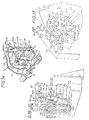
- the plate 55 carries for example eight fixed work stations indicated overall by S1, S2 .... S8, while the turntable 11 carries an equal number of pins indicated generally each by the reference 13, these pins being all similar, and adapted to present a box at each workstation for a specific operation.
- the turntable 11 (fig. 1) is rotated at a pilgrim's step by means of a disc 60 comprising two rollers 60A, 50B alternately anchoring with the aforementioned Saint Andrew's cross 54, this disc itself being driven in rotation by an electric motor 14 through a known reducer 14A in itself.
- a transmission 61 is adapted to rotate a camshaft 62 adapted to control a complete distribution circuit, for example hydraulic, not shown, connected to the movable members (pushers, reel devices, etc.) equipping the control stations. fixed work, which will now be described in more detail.
- the work station Si ( Figures 1, 2, 3 and 11, 12 in particular) comprises a base 65, in the general shape of a horseshoe, fixed by one end of a branch to the plate 55, while the end of the other branch projects beyond the periphery of the plate. Between the two aforementioned branches the base has an opening 65A.
- the base 65 On its upper face, the base 65 carries two application members 26, 27, facing each other and adjustable in spacing parallel to the general plane of the plate thanks to lights 26A, 27A; these application members can be locked in a chosen position, for example by screws 26B, 27B, carried by the base and passing through the aforementioned slots.
- the ends facing the application members 26, 27 are provided with brushes 28 advantageously provided with a coating of plastic sheet; the base 65 (fig. 2) also carries, by means of columns 66 fixed to the latter, a support plate 24.
- the support plate 24 can be more or less spaced from the base (arrow F) and locked in the chosen position by a screw 67 cooperating with a column.
- the plate 24 further comprises an opening 25 intended to be substantially above the opening 65A formed in the base 65.
- the application members are not constituted by brushes, ais by rollers mounted for rotation at the end of the arm likely to occupy a chosen angular position and which can also be separated from one another for example because of sliding mounting on the base 65.
- the fixed station S2 (figs. 1, 4 and 13) comprises an L-shaped base 70, one branch of which is fixed to the plate 55 in any suitable manner, for example screw or welding, while the other branch carries a base 71 on which is fixed a jack 71A whose piston rod 7lB is coupled to a mobile application member 29 carrying a brush 30; the base 71 is also suitable for carrying bearings 72 in which two rods 73 can slide, arranged on either side of the jack, which rods are, at one end, fixed to said application member 29, and by another end, connected by a spacer 73A.
- the applicator member is thus guided during its movements from a retracted position to an advanced position and vice versa.
- the base 71 with the equipment that it carries, is associated with the base 70 by means of a slide 74 allowing its adjustment in position in a direction perpendicular to the axis of the jack 71A, so that the brush 30 can be brought to the correct height depending on the section of the box and blocked with a 74A screw.
- the fixed work station S3 (figs. 1, 5 and 14) comprises a jack 75 carried by a structure 78 slidingly mounted parallel to the plane of the plate and lockable at will in a support 76 by means of two small columns 77 and locking screw 77A, the support 76 being secured to the fixed plate 55.
- the piston rod of the cylinder 75 carries an applicator member 31 provided with a brush 32 with coating in plastic sheet.
- the brush can advantageously be replaced by a roller mounted for rotation on an axis carried by yokes associated with the applicator member 31.
- control unit plication 31 is associated with guide rods 79 sliding in bearings 80 formed in the aforementioned structure, these guides being braced by a plate 81.
- the plate 55 forms (FIG. 1 in particular) a roller 21 whose role is to cooperate with a cam provided on the spindle, which will be described later, in order to rotate the box a quarter turn along its axis.
- the fixed station S4 (figs. 1, 6 and 15) comprises a base 85 in the shape of a stirrup, one branch of which is secured to the plate 55, while the other branch projects beyond the periphery thereof; an opening 86 is thus formed between the two branches of the base which carries a structure having two pairs of folding members 33 to 36 movable in a direction parallel to the plane of the plate.
- This structure comprises: a pair of beams, for example with a U87 section, 38 parallel to each other and to the plate 55, the beam 87 being provided with an opening to allow the passage of the pins 13; inside the longitudinal member 88 are fixed two jacks in opposition 89, 90, the piston rods 89A, 90A of which are coupled to carriages 91, 92, sliding on a guide bar 93 secured at its ends to the longitudinal member 88.
- each of the carriages carries on the other hand, a triangulated framework, having a transverse arm 97, 98 whose free end is guided in a slot 99 formed in the beam 87.
- the two pairs of members 33 to 36 are mounted sliding and lockable at will in a selected position on the transverse arms 97, 98, by means of sockets respectively 33A, 34A, 35A, 36A, so as to allow their positioning on the arms according to the configuration of the box to be covered.
- the actual folding members 33 to 36 are removably mounted on the sockets so to allow a quick change of these depending on the section of a series of boxes to be covered.
- the plate 55 carries a roller 22 capable of cooperating with a cam mounted on each of the spindles to rotate the box a quarter of a turn along its axis.
- the fixed workstation S5 (figs. 1, 7 and 16) has a configuration similar to the fixed workstation S4.
- folding members 37 to 40 which are movable parallel to the plane of the plate 11 and the plate 55 can be easily disassembled and replaced by others depending on the nature of the work to be performed.
- the work station S6 (figs. 1, 8, 17 and 18) is arranged on a bracket 141 fixed to the plate 55; it comprises, mounted sliding on the plate by means of a dovetail, 142, two uprights 143,143A, spaced from one another forming supports for a sleeve 44 fixed in rotation on these uprights, which sleeve receives internally towards each of its ends a bearing 144A.
- the sleeve in question carries a first core 145 on which is fixed a pair of diametrically opposed arms 146, 146A, and a second core 147 on which is fixed another pair of diametrically opposed arms 148,148A, the above cores are articulated on the sleeve in the manner of the branches of a chisel.
- Each of the arms thus formed carries at will a folding member 41 to 44 (fig. 8), or two folding members facing each other 41 to 44 and 41A and 44A (figs. 17,18); the association of the aforementioned reel members with the corresponding arms, being similar for all the reel members, it will only be described below the mounting of two reel devices associated with an arm.
- the folding members 41,41A, associated with the arm 146 are mounted adjustable at will on blades 150,150A, themselves fixed to a bar 151 of orientation perpendicular to the plate; the aforementioned bar 151 is carried by a block 152 mounted sliding on an arm, it is also sliding on this arm by means of a longitudinal light 15lA and lockable at will by means of a pressure button. 153.
- a station comprising four folding members 41 to 44 adapted to fold the corners formed at one end of the box and four folding members 41A to 44A adapted to fold the corners formed at the other end of the box by acting along the diagonals of it.
- the aforementioned pinion 160 is wedged on a shaft 161, rotatably mounted in the bearings 144A and its rotation drive is carried out (fig. 17) by a toothed wheel 165 wedged on this shaft, which cooperates with a rack 166 constituting the end part of the piston rod of a jack 167 mounted oscillating at 168 on a yoke 169 fixed to the bracket 141.
- a retaining roller 172 is provided, rotatably mounted on a support 173 fixed to the plate 55.
- the above arrangement makes it possible to adjust the pusher members in position according to whether the boxes to be treated have a square or rectangular section; indeed, the adjustment is carried out on the one hand, by angularly orienting the blocks 145, 147 relative to the sleeve. 144, and, on the other hand, by orienting the pusher members 41 to 44, 41A to 44A, relative to the carrier blade with which they are associated. It should also be noted that the nuts 145 and 147 on which the arms 146, 146A and 148, 148A are respectively fixed, can be locked, after adjustment, on the fixed sleeve 144 by means of pressure screws 174 (fig. 18 ).
- the fixed workstation S7 (fig. 19) includes a support 220 substantially horseshoe having three branches respectively 220A, 220B, 220C, this support being fixed to the plate 55 by the branch 220A.
- the branches 220A, 220B are arranged to house one, a cylinder 221, the other a cylinder 222, the piston rods 22lA, 222 of which carry an applicator member 50, 51; the two aforementioned cylinders are located in the same plane and in opposition,
- the branch 220B is provided at its free end with a fitting 223 on which is fixed, by means of balusters 224, a jack 225 whose piston rod 226 is coupled to a member 45 carrying a roller 47 whose utility will appear later.
- the branch 220C of the support is arranged to receive a jack 230 whose piston rod 230A is linked to an application member 49. All the application members 49, 50, 51 are associated with rods 231 which are parallel to each other and to the axis of the respective cylinders, which are slidably mounted in bearings 232 provided for this purpose on the base.
- the jacks 225, 230 have their axes perpendicular to the planes of the plate 55 and the turntable 11, while the jacks 221, 222 have their axes parallel to the planes of the aforementioned members 55 and 11.
- the plate 55 carries a roller 23 adapted to cooperate with a cam carried by a spindle to cause the box to make a quarter turn along its axis.
- the fixed workstation S8 (fig. 20) has a configuration substantially similar to the fixed workstation 57; the same references have been used to designate similar bodies; however, it will be noted that at this station, the branch 220C of the support carries a jack 250 whose piston rod 251 is, at its end, equipped with a bellows 252 in communication by an associated connector 253 with a suction source.
- a pin 13 will now: be described in more detail, in particular with reference to FIGS. 21 and 23.
- the spindle 13 is engaged in a spindle support 329 fixed on a rear face of the turntable 11; the axis of this spindle support is parallel to the general axis x-x.
- the aforementioned spindle support houses the rear part 13A of the spindle 13, while the front part, overhanging the plate 55, receives a mandrel 15.
- the rear part 13A of the spindle is rotatably mounted in the spindle support 329 about an axis X'-X parallel to the general axis XX: on its outer surface of this spindle part has four indentations 333 regularly distributed along a circumference, adapted to cooperate with a stabilizing device constituted by a ball 334 subjected to the action of a spring 335.
- the spindle 13 further comprises an axial duct 336 extending from one end to the other of the latter, so that said duct opens into a passage 337 formed in the mandrel 15 and in a connection enclosure 338 it - even connected, by pipeline 339, to a distributor 340 connected by tubing 341, to an annular manifold 342 formed between the sleeve 51 and the shaft 50; this collector is in communication with a suction source, not shown here, by means of at least one radial passage 343 formed in the shaft 50, and a connector 344; the shaft 50 being of course closed at its other end by a plug 345.
- Each of the pins 13 is thus connected, through a distributor, to a suction source, the sleeve 51 comprising for this purpose a series of radial passages to which the pipes 341 are connected.
- the distributor 340 is fixed to the turntable 11, and it is actuated (fig. 22 in particular) when it is presented in front of a ramp 346 fixed on the face of the plate 55 which is opposite the turntable 11, this ramp cooperating with a roller 347 associated with a pusher 348 pivotally mounted on said distributor.
- the aforementioned ramp 346 and the distributor 340 are adapted to ensure, when they cooperate, to cut the power supply to the suction circuit so as to premire the extraction of the mandrel 15 from the dressed box B, this extraction taking place at station S8; since the plate 55 only carries a ramp 346 the distributors are actuated only once during their journeys, they maintain a suction in the pipes and, consequently, at the level of the mandrels, so that the boxes are kept pressed against the chucks throughout their journey.
- a cam 19 is wedged on the spindle 13, it is intended to cooperate with the aforementioned fixed rollers 21 to 23, to rotate said spindle, by a quarter of a turn, and it has for this purpose four peripheral depressions 351 regularly distributed ( fig. 14).
- the spindle 13 In front of this cam 19, the spindle 13 has a grooved outer surface 352 on which is engaged a cap 16 which is integral in rotation with the spindle 13 while being capable of axial sliding on the latter.
- the operation is as follows.
- the adhesive covering strip p (fig. 2) is prepared, the length of which is slightly greater than the perimeter of the tubular element B and the width of which is slightly greater than the height of the tubular element B to form the overflowing DO and DE.
- the tubular element B is partially applied to a middle part M of the strip portion P on the adhering face thereof, leaving the protruding DO and DF protruding.
- the mandrel 15 In the passage of the mandrel 15 between the station S3 and S4, the mandrel is allowed to turn a quarter of a turn under the control of the roller 21 which acts on the cam 19.
- the folding members 33, 34, 35 and 36 are actuated and fold down on two opposite sides the overhanging DO and DF along the closed ends DF and open EO, then the mandrel passes from the station S4 at station S5. During this passage, it is allowed to turn a quarter of a turn under the action of the roller 22 which acts on the cam 19.
- the folding members 37, 38, 39 and 40 fold the remaining sides of the overhangs D F and DO over the closed EF and open EO ends of the box B.
- the mandrel 15 passes to the station; 6 (figs. 1, 8, 17 and 18).
- the folding members 41 to 44 as well as the folding members 41A or 44A fold down according to the angles of the box B, the overflows DF on the ends respectively closed EF and open EO of the box then the mandrel 15 reaches the station S7 (figs. 1, 9, 19).
- the applicator member enters the first in play, which has the effect of pressing the protruding DF well against the closed end of the EF box and applying the edge of the the packaging on the edge of the box; the control 45 is immediately after slaved and makes the cap 16 slide along the spindle 47 along the spindle and brings the latter in. engagement in the open end EO of the box, which has the effect of reinforcing the overflowing DO already folded into the box at post 54.55.
- the mandrel 15 passes from the station S7 to the station S8. During this movement (fig.l), the mandrel is allowed to turn a quarter of a turn under the effect of the roller 23 acting on the cam 19.
- each mandrel 15 is connected to a suction source using the means described above.
- the suction in the mandrel 15 is cut by the action of the roller 347 on the distributor 340 under the effect of the cam 346; the jack 250 is then pressurized and the suction is brought into the bellows 252, so that the box B is extracted from the mandrel 15, then entered manually after cutting off the suction in the bellows.
- all the jacks are controlled from the control center 63 in. so that the machine can process seven boxes at the same time continuously as long as the station Sl is supplied.
- a box is generally made up of two parts, namely a first part called a bell, fitting at least partially, on a second part called a base.
- the covering of a part of a box with a sheet lets appear on one side a line coming from the fact that the starting sheet is dimensioned so that a marginal strip on one side superimposes the other side, which forms the line in question.
- the line of the base and the line of the bell must be in line with one another.
- the invention provides for the use of two machines, one being in accordance with that described above, capable of carrying out the dressing, while the other is intended for dressing of sochts.
- this other machine is similar to that described above, but the work stations and the direction of rotation of the turntable 55 are reversed.
- the position SI is in place of the position S5, the position S2 in place of the position S4, the position S3 remaining in place, the position S4 in place of the position S2 and so on.
Abstract
Procédé et machine pour habiller un élément tubulaire. La machine comporte des postes S1, S2, S3, S4, S5, S6, S7 et S8 où une portion de bande est enroulée autour de la paroi latérale de l'élément tubulaire B et où des débordants de cette portion de bande sont pour l'un renfoncé dans une extrémité ouverte de l'élément tubulaire et pour l'autre, appliqué sur une extrémité fermée de cet élément tubulaire. Applications: habillage de boîtes, notamment de boîtes cloches.Method and machine for covering a tubular element. The machine comprises stations S1, S2, S3, S4, S5, S6, S7 and S8 where a portion of strip is wrapped around the side wall of the tubular element B and where protrusions of this portion of strip are for the 'a recessed in an open end of the tubular element and for the other, applied to a closed end of this tubular element. Applications: dressing of boxes, in particular of bell boxes.
Description
La présente invention se rapporte à un procédé et à une machine pour habiller un élément tubulaire notamment pour habillage d'une boîte, plus particulièrement pour l'habillage avec une feuille de papier ou autre matière, de boîtes, dites boîtes cloches, en carton., utilisées pour l'emballage dans la parfumerie et toutes autres applications, ledit élément tubulaire pouvant avoir une section quelconque, ronde, ovale, carrée, polygonale avec des angles vifs ou arrondis etc.. et avoir toute hauteur voulue, longue ou courte.The present invention relates to a method and to a machine for covering a tubular element, in particular for covering a box, more particularly for covering with a sheet of paper or other material, boxes, called bell boxes, made of cardboard. , used for packaging in perfumery and all other applications, said tubular element being able to have any section, round, oval, square, polygonal with sharp or rounded angles, etc. and to have any desired height, long or short.
Jusqu'à présent, l'habillage de boîtes sur machine ne permet pas de réaliser des boîtes dont la hauteur est relativement grande par rapport aux dimensions de la base comme le sont les boîtes cloches.Up to now, the dressing of boxes on a machine has not made it possible to produce boxes whose height is relatively large compared to the dimensions of the base, as are bell boxes.
Cet habillage sur machine s'applique en pratique seulement à des boîtes parallélépipédiques d'une hauteur relativement réduite par rapport aux dimensions de la base et présentant des arêtes vives. Dans ces machines, on découpe à l'avance un habillage en forme de croix et on le place sous la base de la boîte que l'on veut habiller et l'on fait tourner les côtés opposés de l'habillage autour des arêtes inférieures de la boîte. Une telle machine ne permet pas l'habillage des boîtes cloches lesquelles sont donc généralement habillées à la main.This machine covering applies in practice only to rectangular boxes of a relatively reduced height compared to the dimensions of the base and having sharp edges. In these machines, we cut a cross-shaped covering in advance and place it under the base of the box that we want to cover and we rotate the opposite sides of the covering around the lower edges of the box. Such a machine does not allow the covering of the bell boxes which are therefore generally dressed by hand.
La présente invention a pour objet un procédé pour habiller un élément tubulaire de section quelconque et de toute hauteur, grande ou petite, permettant un habillage automatique sur machine.The subject of the present invention is a method for covering a tubular element of any section and of any height, large or small, allowing automatic dressing. on machine.
Suivant l'invention, un procédé pour habiller un élément tubulaire est caractérisé en ce que l'on part d'une portion de bande d'habillage adhérisante, dont la longueur est légèrement supérieure au périmètre de l'élément tubulaire et dont la largeur est légèrement supérieure à la hauteur de l'élément tubulaire, on applique ledit élément tubulaire sur une partie médiane de la portion de bande, en laissant dépasser au moins un débordant, on engage sur un mandrin ledit élément tubulaire ainsi partiellement appliqué et adhérisé sur ladite portion de bande, on enroule ladite portion de bande autour de l'élément tubulaire engagé sur le mandrin, en ce que pour cet enroulement, on relève les parties latérales de la portion de bande de part et d'autre de l'élément tubulaire en les faisant adhériser avec des dépassants au-dessus de l'élément tubulaire et on exerce sur les dépassants des parties latérales relevées des actions de rabattement pour les amener et les faire adhériser, avec un léger recouvrement, sur l'élément tubulaire engagé sur le mandrin, en ce que l'on rabat ledit débordant de la portion de bande en regard d'une extrémité ouverte de l'élément tubulaire engagé sur le mandrin et en ce que l'on renfonce ce débordant dans ladite extrémité ouverte de l'élément tubulaire engagé sur le mandrin, en exerçant une action axiale sur ledit débordant par un organe, dit casquette, ayant une même section que le mandrin et monté solidaire angulairement et mobile en translation par rapport audit mandrin.According to the invention, a method for covering a tubular element is characterized in that one starts from a portion of adhering covering strip, the length of which is slightly greater than the perimeter of the tubular element and the width of which is slightly greater than the height of the tubular element, said tubular element is applied to a median part of the strip portion, leaving at least one projecting protrusion, said tubular element is thus partially applied and adhered to said portion on a mandrel strip, said strip portion is wound around the tubular element engaged on the mandrel, in that for this winding, the lateral parts of the strip portion are raised on either side of the tubular element making adhere with protruding above the tubular element and is exerted on the protruding side parts raised folding actions to bring them and make them adhere, with a slight rec openly, on the tubular element engaged on the mandrel, in that said protruding overhang of the strip portion is folded opposite an open end of the tubular element engaged on the mandrel and in that it is recessed this projecting into said open end of the tubular element engaged on the mandrel, by exerting an axial action on said projecting member, said cap, having the same section as the mandrel and mounted angularly and movable in translation with respect to said mandrel .
Grace à cette disposition et en partant d'une portion de bande d'habillage et non pas d'une découpe en forme de croix, on assure d'une manière qui peut être automatisée sur machine un enroulement irréprochable de la portion de bande autour de l'élément tubulaire avec un léger recouvrement et sans aucun risque de partie bouffante, et ceci quelle que soit la section de l'élément tubulaire et quelle que soit sa hauteur tandis que le renfoncement du débordant est réalisé sans que l'élément tubulaire ait à être enlevé du mandrin, ce qui permet de réaliser l'opération d'enroulement et l'opération de renfoncement sur la même machine, remarque étant faite que la casquette de renfoncement montée solidairement angulairement et mobile en translation par rapport au mandrin est admise seulement à être rapprochée et écartée axialement lu mandrin, sans interpénétration de cette casquette et du mandrin.Thanks to this arrangement and starting from a portion of the covering strip and not from a cross-shaped cutout, an impeccable winding of the strip portion is ensured in a manner which can be automated on the machine. the tubular element with a slight overlap and without any risk of puffing part, and this whatever the section of the tubular element and whatever its height while the recess of the overhang is carried out without the tubular element having to be removed from the mandrel, which makes it possible to carry out the winding operation and the recessing operation on the same machine, note that the case indentation wedge mounted integrally angularly and movable in translation relative to the mandrel is only allowed to be brought closer and apart axially read the mandrel, without interpenetration of this cap and the mandrel.
La présente invention a également pour objet une machine pour habiller un élément tubulaire dont la construction est particulièrement simple et robuste et permet d'habiller une pluralité d'éléments tubulaires avec une grande cadence, en assurant les opérations d'enroulement et de renfoncement et également, s'il y a lieu, d'autres opérations encore utiles pour les besoins de l'habillage, par exemple le rabattement d' un deuxième débordant sur une extrémité fermée de l'élément tubulaire opposée à l'extrémité ouverte, et ceci d'une manière irréprochable, c'est-à-dire sans aucune partie bouffante ni faux plis.The present invention also relates to a machine for dressing a tubular element whose construction is particularly simple and robust and allows to dress a plurality of tubular elements with a high rate, ensuring the operations of winding and recessing and also , if necessary, other operations that are still useful for dressing purposes, for example the folding down of a second projecting over a closed end of the tubular element opposite the open end, and this d 'an impeccable manner, that is to say without any puffy parts or creases.
Suivant l'invention, une machine pour habiller un élément tubulaire est caractérisée en ce qu'elle comporte un bâti fixe, un plateau monté tournant sur ledit bati autour d'un axe général, ledit bâti ayant une pluralité de postes fixes pour un enroulement d'une portion de bande d'habillage adhérisante autour de l'élément tubulaire et pour un renfoncement d'un débordant de ladite portion de bande dans une extrémité ouverte dudit élément tubulaire, ledit plateau tournant ayant une pluralité de broches parallèles audit axe général, chaque broche portant solidairement un mandrin de même section que l'élément tubulaire et, d'une manière solidaire angulairement et libre en translation, une casquette de même section que le mandrin, des moyens de commande en. rotation du plateau pour amenersuc- cessivement lesdites broches auxdits postes, des moyens d'enroulement de ladite portion de bande autour de l'élément tubulaire engagé sur le mandrin et des moyens pour déplacer en translation la casquette par rapport au mandrin entre une position écartée et une position rapprochée pour renfoncer le débordant de la portion de bande dans l'extrémité ouverte de l'élément tubulaire.According to the invention, a machine for dressing a tubular element is characterized in that it comprises a fixed frame, a plate mounted rotating on said frame around a general axis, said frame having a plurality of fixed stations for winding d 'a portion of covering strip adhering around the tubular element and for a recess of a protrusion of said strip portion in an open end of said tubular element, said turntable having a plurality of pins parallel to said general axis, each spindle integrally carrying a mandrel of the same section as the tubular element and, in an angularly integral manner and free in translation, a cap of the same section as the mandrel, control means in. rotation of the plate for successively bringing said pins to said stations, means for winding said portion of strip around the tubular element engaged on the mandrel and means for translating the cap relative to the mandrel between a spaced position and a close position to push the projecting portion of the strip portion into the open end of the tubular element.
Dans cette machine, il y a ainsi une pluralité de postes ayant chacun une fonction précise et normalement autant de broches portant chacune un mandrin et une casquette, par exemple huit postes et huit broches avec une symétrie circulaire. De ce fait, la machine traite simultanément sept éléments tubulaires.In this machine, there is thus a plurality of stations each having a precise function and normally as many pins each carrying a mandrel and a cap, for example eight stations and eight pins with circular symmetry. As a result, the machine simultaneously processes seven tubular elements.
La machine tourne avec un pas de pélerin pour amener successivement chaque broche aux différents postes.The machine turns with a pilgrim step to successively bring each spindle to the different stations.
Au premier poste, on engage sur le mandrin qui s'y trouve l'élément tubulaire que l'on a préalablement partiellement appliqué et adhérisé sur la portion de bande, en disposant cet élément tubulaire de telle façon que la portion de bande se trouve du côté amont dans le sens de rotation du plateau de la machine. Lorsque le plateau tourne pour amener le mandrin du premier au deuxième postes, des organes fixes d'application, de préférence des brosses dotées d'un revêtement plastique, font relever les parties latérales de la portion de bande de part et d'autre de l'élément tubulaire en les faisant adhériser avec des dépassants au-dessus de l'élément tubulaire.Lorsque le mandrin parvient au deuxième poste, un organe mobile d'application, par exemple formé par une brosse dotée d'un revêtement plastique, balaye le dépassant d'une des parties latérales relevées pour l'amener et le faire adhériser sur l'élément tubulaire. Lorsque le mandrin arrive au troisième poste, un autre organe mobile d'application, analogue au précédent et de préférence formé par une brosse dotée d'un revêtement plastique, balaye le dépassant de l'autre partie latérale relevée pour le rabattre et le faire adhériser avec un léger recouvrement sur le premier dépassant rabattu et adhérisé au deuxième poste.At the first station, the tubular element which has been partially applied and adhered to the strip portion is engaged on the mandrel which is therein, placing this tubular member in such a way that the strip portion is located upstream side in the direction of rotation of the machine table. When the plate turns to bring the mandrel from the first to the second station, fixed application members, preferably brushes provided with a plastic coating, raise the lateral parts of the strip portion on either side of the tubular element by making them adhere with protrusions above the tubular element. When the mandrel reaches the second station, a mobile application member, for example formed by a brush provided with a plastic coating, sweeps the protruding one of the side parts raised to bring it and make it adhere to the tubular element. When the mandrel arrives at the third station, another mobile application member, similar to the previous one and preferably formed by a brush provided with a plastic coating, sweeps beyond the other raised side part to fold it down and make it adhere with a slight overlap on the first protruding folded down and adhered to the second post.
Dans un poste suivant, la casquette est rapprochée en translation du mandrin pour renfoncer dans l'extrémité ouverte de l'élément tubulaire le débordant qui a été préalablement rabattu pour donner prise à la casquette. La machine comporte avantageusement d'autres postes encore pour améliorer les conditions d'application et également, s'il y a lieu, appliquer un deuxième débordant sous une extrémité fermée de l'élément tubulaire opposée à l'extrémité ouverte à titre d'exemple, en référence aux dessins annexés dans lesquels :
- la figure 1 est une vue schématique générale en élévation d'une machine suivant l'invention pour habiller un élément tubulaire, notamment une boîte cloche ;
- la figure 2 illustre en perspective un premier poste où l'on a engagé sur le mandrin l'élément tubulaire partiellement appliqué et adhérisé sur une partie médiane de la portion de bande ;
- la figure 3 montre le relèvement des parties latérales des portions de bande par des organes d'application fixes lorsque le mandrin quitte le premier poste pour passer au deuxième poste ;
- la figure 4 illustre à ce deuxième poste le rabattement du dépassant d'une des parties latérales relevées pour l'appliquer et l'adhériser sur l'élément tubulaire sous l'action d'un organ.e d'application mobile ;
- la figure 5 illustre au troisième poste l'application du dépassant de la deuxième partie latérale relevée sur l'élément tubulaire avec un léger recouvrement sur le premier dépassant déjà appliqué au deuxième poste ;
- la figure 6 montre le quatrième poste où des organes de rabattement rabattent les débordants suivant deux côtés opposés ;
- la figure 7 montre le cinquième poste où des organes de rabattement rabattent les débordants suivant les deux autres côtés opposés ;
- la figure 8 montre le sixième poste où des organes de rabattement appliquent les angles d'un débordant sur une extrémité fermée de l'organe tubulaire ;
- la figure 9 montre le septième poste où la casquette, admise à être rapprochée axialement du mandrin, renfonce le débordant dans l'extrémité ouverte de l'élément tubulaire, tandis qu'un pressage est exercé, d'une part sur les deux extrémités de l'élément tubulaire et, d'autre part, suivant deux côtés opposés, au voisinage de l'extrémité ouverte de 1' élément tubulaire alors que la casquette se trouve engagée dans cette extrémité cuverte ;
- la figure 10 montre schématiquement le huitième poste où un pressage est exercé suivant les deux autres côtés opposés au voisinage de l'extrémité ouverte de l'élément tubulaire alors que la casquette est encore engagée dans cette extrémité ouverte ;
- les figures 11 et 12 montrent en perspective une forme de réalisation du premier poste fixe ;
- les figures 13 à 16 montrent, également en perspective, une forme de réalisation des second, troisième, quatrième et cinquième postes fixes ;
- la figure 17 illustre en vue de face le sixième poste de travail ;
- la figure 18 est une vue partiellement en coupe correspondant à la figure 17 selon une ligne XVIII-XVIII indiquée sur cette dernière ;
- les figures 19 et 20 montrent en perspective respectivement les septième et huitième postes fixes ;
- la figure 21 est une coupe verticale partielle de la machine, cette coupe passant par l'axe d'une broche porte-mandrin ;
- la figure 22 est une vue en coupe suivant une ligne passant par XXII-XXII de la figure 21 et,
- la figure 23 montre une broche en perspective.
- Figure 1 is a general schematic elevational view of a machine according to the invention for dressing a tubular element, in particular a bell box;
- FIG. 2 illustrates in perspective a first station in which the tubular element partially applied and adhered to a central part of the strip portion has been engaged on the mandrel;
- FIG. 3 shows the raising of the lateral parts of the strip portions by fixed application members when the mandrel leaves the first station to pass to the second station;
- FIG. 4 illustrates at this second station the folding down of the protruding one of the raised lateral parts to apply it and adhere it to the tubular element under the action of a mobile application organ;
- FIG. 5 illustrates in the third station the application of the protrusion from the second lateral part raised on the tubular element with a slight overlap on the first protrusion already applied to the second station;
- Figure 6 shows the fourth station where the folding members fold the overhanging along two opposite sides;
- Figure 7 shows the fifth station where the folding members fold the projecting along the other two opposite sides;
- Figure 8 shows the sixth station where the folding members apply the angles of a projecting on a closed end of the tubular member;
- FIG. 9 shows the seventh position where the cap, admitted to be brought axially closer to the mandrel, pushes the projecting into the open end of the tubular element, while a pressing is exerted, on the one hand on the two ends of the tubular element and, on the other hand, along two opposite sides, in the vicinity of the open end of one tubular element while the cap is engaged in this cup end;
- Figure 10 schematically shows the eighth station where a pressing is exerted along the two other opposite sides in the vicinity of the open end of the tubular element while the cap is still engaged in this open end;
- Figures 11 and 12 show in perspective an embodiment of the first fixed station;
- Figures 13 to 16 show, also in perspective, an embodiment of the second, third, fourth and fifth fixed stations;
- Figure 17 illustrates a front view of the sixth work station;
- Figure 18 is a partially sectional view corresponding to Figure 17 along a line XVIII-XVIII indicated thereon;
- Figures 19 and 20 show in perspective respectively the seventh and eighth fixed positions;
- Figure 21 is a partial vertical section of the machine, this section passing through the axis of a mandrel spindle;
- FIG. 22 is a sectional view along a line passing through XXII-XXII of FIG. 21 and,
- Figure 23 shows a pin in perspective.
Le mode de réalisation représenté aux figures 1 à 23 concerne, à titre d'exemple non limitatif, une application de l' invention à une machine pour habiller un élément tubulaire en carton cu autre matière en forme de boîte cloche B (fig. 2) ayant une extrémité ouverte EO et une extrémité fermée EF,dont la section est carrée avec des angles arrondis et dont la hauteur est relativement grande par rapport aux côtés de la section. Cet habillage est réalisé au moyen d'une feuille de papier p ou autre matière destiné à entourer la paroi latérale de l'élément tubulaire B avec renfoncement d'un débordant DO dans l'extrémité ouverte EO et rabattement d'un débordant DF sur l'extrémité fermée EF.The embodiment shown in Figures 1 to 23 relates, by way of non-limiting example, an application of the invention to a machine for dressing a tubular element of cardboard or other material in the form of a bell box B (Fig. 2) having an open end EO and a closed end EF, the section of which is square with rounded corners and the height of which is relatively large in relation to the sides of the section. This covering is carried out by means of a sheet of paper p or other material intended to surround the side wall of the tubular element B with a protrusion of a protruding DO in the open end EO and folding of an protruding DF on the closed end EF.
Cette machine parmar l'habillage d'un élément tubulaire tel que B ayant une section quelconque ronde, ovale, carrée, polygonale ou autre avec des angles vifs ou arrondis et de toute hauteur voulue, grande ou petite.This machine parmar the dressing of a tubular element such as B having any round, oval, square, polygonal or other section with sharp or rounded angles and of any desired height, large or small.
La feuille de papier d'habillage P qui servira à habiller chaque boîte B est constituée par une portion de bande adhérisante dont les extrémités EP peuvent être droites, comme il est représenté à la figure 2, mais qui pourraient également être inclinées ou avoir toute autre forme pourvu que ces extrémités EF et EP, après enroulement de la bande p sur l'élément B, soient adaptées à venir au voisinage l'une de l'autre, avec un léger recouvrement.The sheet of covering paper P which will be used to cover each box B is constituted by a portion of adhesive tape whose ends EP may be straight, as shown in FIG. 2, but which could also be inclined or have any other shape provided that these ends EF and E P , after winding of the strip p on the element B, are adapted to come in the vicinity of one another, with a slight overlap.
Aux figures 1 et 21 en particulier la machine comporte un bâti fixe 10 et un plateau 11 monté tournant sur le bâti 10 autour d'un arbre d'axe général X-X.In FIGS. 1 and 21 in particular the machine comprises a
Dans l'exemple représenté l'arbre indiqué en 50 est horizontal, il est tubulaire et fixé par une partie terminale, au bâti 10 de la machine en présentant un tronçon en porte-à-faux ; le tronçon en porte-à-faux forme un palier à un manchon 51 coaxial audit arbre et susceptible de rotation sur ce dernier au moyen de roulements usuels 52. Le manchon 51 est calé axialement sur l'arbre 50 par exemple au moyen de circlips 53. et il porte à une de ses extrémités le plateau tournant 11 précité, par exemple circulaire, et à une autre de ses extrémités un moyen d'entraînement constitué par une croix de Sairth-André 54.In the example shown the shaft indicated at 50 is horizontal, it is tubular and fixed by an end portion, to the
Au delà du plateau tournant 11, et en vis-à-vis de celui-ci, est disposée une platine 55 circulaire, dont le diamètre est inférieur à celui du plateau tournant 11, cette platine est solidarisée à l'arbre 50 au moyen d'une clavette 56 et d' écrous 57 ; elle est donc fixe.Beyond the
La platine 55 porte par exemple huit postes fixes de travail indiqués globalement par Sl, S2.... S8, tandis que le plateau tournant 11 porte un nombre égal de broches indiquées globalement chacune par la référence 13, ces broches étant toutes semblables, et adaptées à présenter une boîte à chacun des postes de travail pour une opération déterminée.The
Le plateau tournant 11 (fig. 1) est entraîné en rotation à un pas de pélerin au moyen d'un disque 60 comportant deux galets 60A, 50B angrenant alternativement avec la croix de Saint-André précitée 54, ce disque étant lui-même entraîné en rotation par un moteur électrique 14 à travers un réducteur 14A connu en soi.The turntable 11 (fig. 1) is rotated at a pilgrim's step by means of a
Du réducteur 14A, une transmission 61 est adaptée à entraîner en rotation un arbre à cames 62 adapté à asservir un circuit complet de distribution, par exemple hydraulique, non représenté, connecté aux organes mobiles (pousseurs, rabatteurs etc..) équipant les postes de travail fixes, lesquels vont maintenant être décrits plus en détail.From the
Le poste de travail Si (figures 1, 2, 3 et 11, 12 en particulier) comprend une embase 65, en forme générale de fer à cheval, fixée par une extrémité d'une branche à la platine 55, tandis que l'extrémité de l'autre branche est débordante par rapport à la périphérie de la platine. Entre les deux branches précitées l'embase comporte une ouverture 65A.The work station Si (Figures 1, 2, 3 and 11, 12 in particular) comprises a
Sur sa face supérieure, l'embase 65 porte deux organes d' application 26, 27, se faisant vis-à-vis et réglables en écartement parallèlement au plan général de la platine grace à des lumières 26A, 27A ; ces organes d'application sont blocables dans une position choisie,par exemple par vis 26B, 27B, portées par l'embase et traversant les lumières précitées.On its upper face, the base 65 carries two
Les extrémités se faisant face des organes d'application 26, 27 sont munies de brosses 28 avantageusement dotées d'un revêtement en feuille plastique ; l'embase 65 (fig. 2) porte aussi par l'intermédiaire de colonnettes 66 fixées à cette dernière, une plaque d'appui 24.The ends facing the
La plaque d'appui 24 peut être plus ou moins écartée de l'embase (flèche F) et bloquée en position choisie par une vis 67 coopérant avec une colonnette.The
La plaque 24 comporte en outre une ouverture 25 prévue pour être sensiblement au-dessus de l'ouverture 65A formée dans l'embase 65.The
Suivant une variante de réalisation du poste Sl, les organes d'application ne sont dus constitués par des brosses, ais par des rouleaux montés à rotation à l'extrémité de bras susceptibles d'occuper une position angulaire choisie et qui peuvent en outre être écartés l'un de l'autre par exemple car montage coulissant sur l'embase 65.According to an alternative embodiment of the position Sl, the application members are not constituted by brushes, ais by rollers mounted for rotation at the end of the arm likely to occupy a chosen angular position and which can also be separated from one another for example because of sliding mounting on the
Le poste fixe S2 (figs. 1, 4 et 13) comprend une embase 70 en forme de L dont une branche est fixée à la platine 55 de toute manière appropriée, par exemple vis ou soudure, tandis que l'autre branche porte un socle 71 sur lequel est fixé un vérin 71A dont la tige de piston 7lB est couplée à un organe d'application mobile 29 portant une brosse 30 ; le socle 71 est aussi adapté à porter des paliers 72 dans lesquels peuvent coulisser deux tiges 73 disposées de part et d'autre du vérin, lesquelles tiges sont, par une extrémité,fixées audit organe d'application 29, et par une autre extrémité, reliées par une entretoise 73A. L'organe d'application est ainsi guidé lors de ses déplacements d'une position reculée à une position avancée et vice-versa.The fixed station S2 (figs. 1, 4 and 13) comprises an L-shaped
Le socle 71, avec l'équipement qu'il porte, est associé à l'embase 70 au moyen d'une glissière 74 permettant son réglage en position suivant une direction perpendiculaire à l'axe du vérin 71A, en sorte que la brosse 30 peut être amenée à bonne hauteur selon la section de la boîte et bloquée au moyen d'une vis 74A.The
Il convient en outre de signaler que la brosse 30 sus-indiquée pourrait être remplacée par un rouleau monté rotatif sur l'organe d'application 29.It should also be noted that the
Le poste de travail fixe S3 (figs. 1, 5 et 14) comprend un vérin 75 porté par une structure 78 montée coulissante parallèlement au plan de la platine et blocable à volonté dans un support 76 au moyen de deux colonnettes 77 et vis de blocage 77A, le support 76 étant solidarisé au plateau fixe 55.The fixed work station S3 (figs. 1, 5 and 14) comprises a
La tige de piston du vérin 75 porte un organe d'application 31 pourvu d'une brosse 32 avec revêtement en feuille plastique.The piston rod of the
Ici aussi la brosse peut être avantageusement remplacée par un rouleau monté à rotation sur un axe porté par des chapes associées à l'organe d'application 31.Here too, the brush can advantageously be replaced by a roller mounted for rotation on an axis carried by yokes associated with the
Comme précédemment décrit à la figure 13, l'organe d'application 31 est associé à des tiges guides 79 coulissantes dans des paliers 80 ménagés dans la structure précitée, ces guides étant entretoisés par une plaque 81.As previously described in Figure 13, the
Entre le poste de travail fixe S3, et le poste de travail fixe S4, la platine 55 forme (fig. 1 en particulier) un galet 21 dont le rôle est de coopérer avec une came prévue sur la broche, laquelle sera décrite plus loin, afin de faire tourner la boîte d'un quart de tour suivant son axe.Between the fixed work station S3 and the fixed work station S4, the
Le poste fixe S4 (figs. 1, 6 et 15) comprend une embase 85 en forme d'étrier dont une branche est solidarisée à la platine 55, tandis que l'autre branche déborde à la périphérie de celle-ci ; une ouverture 86 est ainsi formée entre les deux branches de l'embase qui porte une structure ayant deux paires d'organes rabatteurs 33 à 36 mobiles suivant une direction parallèle au plan de la platine.The fixed station S4 (figs. 1, 6 and 15) comprises a base 85 in the shape of a stirrup, one branch of which is secured to the
Cette structure comprend : une paire de longerons par exemple à section en U87, 38 parallèles entre eux et à la platine 55,le longeron 87 étant aménagé avec une ouverture pour permettre le passage des broches 13 ; à l'intérieur du longeron 88 sont fixés deux vérins en opposition 89, 90 dont les tiges de piston 89A, 90A sont attelées à des chariots 91, 92, coulissants sur une barre de guidage 93 solidarisée par ses extrémités au longeron 88.This structure comprises: a pair of beams, for example with a U87 section, 38 parallel to each other and to the
Aux chariots précités sont associées des crémaillères 94, 95, engrenant sur un même pignon 96 monté rotatif sur le longeron 88 ; un tel montage permet d'obtenir une synchronisation des vérins ; chacun des chariots porte d'autre part, une ossature triangulée, ayant un bras transversal 97, 98 dont l'extrémité libre est guidée dans une lumière 99 ménagée dans le longeron 87. Les deux paires d'organes 33 à 36 sont montées coulissantes et blocables à volonté dans une position choisie sur lesbras transversaux 97, 98, au moyen de douilles respectivement 33A, 34A, 35A, 36A, de manière à permettre leur positionnement sur les bras en fonction de la configuration de la boite à recouvrir.The abovementioned carriages are associated with
On notera que les organes rabatteurs proprement dits 33 à 36 sont montés de manière amovible sur les douilles de façon à permettre un changement rapide de ceux-ci en fonction de la section d'une série de boîtes à recouvrir.It will be noted that the
Entre le poste de travail fixe S4 et le poste de travail fixe S5 la platine 55 porte un galet 22 apte à coopérer avec une came montée sur chacune des broches pour faire tourner la boîte d'un quart de tour selon son axe.Between the fixed work station S4 and the fixed work station S5, the
Le poste de travail fixe S5 (figs. 1, 7 et 16) présente une configuration analogue au poste de travail fixe S4.The fixed workstation S5 (figs. 1, 7 and 16) has a configuration similar to the fixed workstation S4.
Il convient de noter ici aussi que les organes rabatteurs 37 à 40 qui sont déplaçables parallèlement au plan du plateau 11 et de la platine 55 peuvent être aisément démontés et remplacés par d'autres selon la nature du travail à effectuer.It should also be noted here that the
Le poste de travail S6 (figs. 1, 8, 17 et 18) est disposé sur une potence 141 fixée à la platine 55 ; il comprend,montés coulissants sur la platine au moyen d'une queue d'aronde,142, deux montants 143,143A, espacés l'un de l'autre formant supports à un manchon 44 fixe en rotation sur ces montants,lequel manchon reçoit intérieurement vers chacune de ses extrémités un roulement 144A.The work station S6 (figs. 1, 8, 17 and 18) is arranged on a bracket 141 fixed to the
Le manchon en question porte un premier noyau 145 sur lequel est fixée une paire de bras diamétralement opposésl46, 146A, et un second noyau 147 sur lequel est fixée une autre paire de bras 148,148A, diamétralement opposés, les noyaux ci-dessus sont articulés sur le manchon à la manière des branches d'un ciseau.The sleeve in question carries a
Chacun des bras ainsi formés porte à volonté un organe rabatteur 41 à 44 (fig. 8), ou deux organes rabatteurs en vis - à-vis 41 à 44 et 41A et 44A (figs. 17,18) ; l'association des organes rabatteurs précités aux bras correspondants, étant similaire pour tous les organes rabatteurs, il ne sera décrit ci-après que le montage de deux rabatteurs associés à un bras.Each of the arms thus formed carries at will a folding
En référence plus particulièrement aux figures 17,18,les organes rabatteurs 41,41A, associés au bras 146, sont montés réglables à volonté sur des lames 150,150A, elles-mêmes fixées à une barrette 151 d'orientation perpendiculaire à la platine ; la barrette précitée 151 est portée par un bloc 152 monté coulissant sur un bras, elle est aussi coulissante sur ce bras au moyen d'une lumière longitudinale 15lA et blocable à volonté au moyen d'un bouton de pression. 153.Referring more particularly to FIGS. 17,18, the
On obtient ainsi un poste comportant quatre organes rabatteurs 41 à 44 adaptés à rabattre les coins formés à une extrémité de la boîte et quatre organes rabatteurs 41A à 44A adaptés à rabattre les coins formés à l'autre extrémité de la boîte en agissant suivant les diagonales de celle-ci.A station is thus obtained comprising four
La commande simultanée de tous les organes rabatteurs est assurée au moyen de crémaillères 155 à 158 fixées à chaque bloc 152 ; les crémaillères précitées 155 à 158 coopèrent avec un pignon 160, en sorte que,lorsque celui-ci est commandé en rotation,tous les organes de pression sont déplacés simultanément soit vers la boite, pour effectuer le rabattement des pliures de coins, soit au contraire pour libérer celle-ci une fois l'opération terminée.The simultaneous control of all the folding members is ensured by means of
Le pignon précité 160 est calé sur un arbre 161, monté rotatif dans les roulements 144A et son entraînement en rotation est effectué (fig. 17) par une roue dentée 165 calée sur cet arbre, laquelle coopère avec une crémaillère 166 constituant la partie terminale de la tige de piston d'un vérin 167 monté oscillant en 168 sur une chape 169 fixée à la potence 141.The
Afin que la crémaillère 166 n'échappe à la roue dentée 165 pendant une opération, il est prévu un galet de retenue 172 monté tournant sur un support 173 fixé à la platine 55.So that the rack 166 does not escape the
La disposition ci-dessus permet d'ajuster les organes poussoirs en position selon que les boîtes à traiter présentent une section carrée ou rectangulaire ; en effet, l'ajustement est effectué d'une part, en orientant angulairement les blocs 145,147 par rapport au manchon. 144, et, d'autre part, en orientant les organes pousseurs 41 à 44, 41A à 44A, par rapport à la lame porteuse à laquelle ils sont associés. Il convient en outre de noter que les noix 145 et 147 sur lesquelles sont respectivement fixés les bras 146, 146A, et 148, 148A, sont blocables, après ajustement, sur le manchon fixe 144 au moyen de vis de pression 174 (fig. 18).The above arrangement makes it possible to adjust the pusher members in position according to whether the boxes to be treated have a square or rectangular section; indeed, the adjustment is carried out on the one hand, by angularly orienting the
Le poste de travail fixe S7 (fig. 19) comprend un support 220 sensiblement en fer à cheval présentant trois branches respectivement 220A, 220B, 220C, ce support étant fixé à la platine 55 par la branche 220A.The fixed workstation S7 (fig. 19) includes a
Les branches 220A, 220B, sont aménagées pour loger l'une, un vérin 221, l'autre un vérin 222, dont les tiges de piston 22lA,222 portent un organe d'application 50, 51 ; les deux vérins précités sont situés dans un même plan et en opposition,The
La branche 220B est munie à son extrémité libre d'une ferrure 223 sur laquelle est fixé, par l'intermédiaire de colonnettes 224, un vérin 225 dont la tige de piston 226 est accouplée à un organe 45 portant un galet 47 dont l'utilité ap- paraitra plus loin.The
La branche 220C du support est aménagée pour recevoir un vérin 230 dont la tige de piston 230A est liée à un organe d' application 49. Tous les organes d'application 49, 50, 51 sont associés à des tiges 231 parallèles entre elles et à l'axe des vérins respectifs, qui sont montées coulissantes dans des paliers 232 prévus à cet effet sur l'embase.The
Les vérins 225, 230, ont leurs axes perpendiculaires aux plans de la platine 55 et du plateau tournant 11, tandis que les vérins 221, 222, ont leurs axes parallèles aux plans des organes précités 55 et 11.The
Entre les postes fixes S7, S8, la platine 55 porte un galet 23 adapté à coopérer avec une came portée par une broche pour faire effectuer à la boîte un quart de tour suivant son axe.Between the fixed stations S7, S8, the
Le poste de travail fixe S8 (fig. 20) présente une configuration sensiblement analogue au poste fixe 57 ; les mêmes références sont été reprises pour désigner des organes similaires ; toutefois on notera qu'à ce poste la branche 220C du support porte un vérin 250 dont la tige de piston 251 est, à son extrémité, équipée d'un soufflet 252 en communication par un raccord associé 253 avec une source de succion.The fixed workstation S8 (fig. 20) has a configuration substantially similar to the fixed
Une telle disposition permet d'extraire la boîte B du mandrin 13 par l'amenée du soufflet 227 au contact de l'extrémité fermée E-F de la boite, avec simultanément mise en communication du soufflet avec la source ce succion.Such an arrangement makes it possible to extract the box B from the
Une broche 13 va maintenant: être décrite plus en détail notamment en référence aux figures 21 et 23.A
La broche 13 est engagée dans un support de broche 329 fixé sur une face postérieure du plateau tournant 11 ; l'axe de ce support de broche est parallèle à l'axe général x-x. Le support de broche précité loge la partie postérieure 13A de la broche 13, tandis que la partie antérieure, surplombant la platine 55, reçoit un mandrin 15.The
La partie postérieure 13A de la broche est montée tournante dans le support de broche 329 autour d'un axe X'-X parallèle à l'axe général X-X : sur sa surface extérieure de cette partie de broche comporte quatre empreintes 333 régulièrement réparties suivant une circonférence, adaptées à coopérer avec un dispositif stabilisateur constitué par une bille 334 soumise à l'action d'un ressort 335.The
La broche 13 comporte, de plus, un conduit axial 336 s'étendant d'une extrémité à l'autre de cette dernière, en sorte que ledit conduit débouche dans un passage 337 ménagé dans le mandrin 15 et dans une enceinte de raccordement 338 elle-même connectée, par canalisation 339, à un distributeur 340 relié par tubulure 341, à un collecteur annulaire 342 ménagé entre le manchon 51 et l'arbre 50 ; ce collecteur est en communication avec une source de succion, non représentée ici, au moyen d'au moins un passage radial 343 ménagé dans l'arbre 50, et d'un raccord 344 ; l'arbre 50 étant bien entendu obturé à son autre extrémité par un bouchon 345.The
Chacune des broches 13 est ainsi reliée, à travers un distributeur, à une source de succion, le manchon 51 comportant à cet effet une série de passages radiaux sur lesquels sont raccordées les tubulures 341.Each of the
Le distributeur 340 est fixé au plateau tournant 11, et il est actionné (fig. 22 en particulier) lorsqu'il est présenté devant une rampe 346 fixée sur la face de la platine 55 qui est en regard du plateau tournant 11, cette rampe coopérant avec un galet 347 associé à un poussoir 348 monté pivotant sur ledit distributeur.The
La rampe précitée 346 et le distributeur 340 sont adaptés à assurer, lorsqu'ils coopèrent, à couper l'alimentation du circuit de succion en sorte de premettre l'extraction du mandrin 15 de la boîte habillée B, cette extraction se faisant au poste S8 ; étant donné que la platine 55 ne porte qu'une rampe 346 les distributeurs sont actionnés une seule fois lors de eurs parcours, ils maintiennent une succion dans les canalisations et, partant, au niveau des mandrins, en sorte que les boîtes sont maintenues plaquées contre les mandrins pendant tout leur cheminement.The aforementioned ramp 346 and the
Une came 19 est calée sur la broche 13, elle est destinée à coopérer avec les galets fixes précités 21 à 23, pour faire tourner ladite broche, d'un quart de tour, et elle comporte à cet effet quatre dépressions périphériques 351 régulièrement réparties (fig. 14).A
En avant de cette came 19, la broche 13 comporte une surface extérieure cannelée 352 sur laquelle est engagée une casquette 16 qui est solidaire en rotation de la broche 13 tout en étant susceptible de coulissement axial sur cette dernière.In front of this
Il est à noter que la machine qui vient d'être décrite peut être adaptée, en fonction des formes et dimensions des boites à habiller, en procédant au changement d'organes tels que mandrin, casquette, organes pousseurs et rabatteurs de configuration adéquate, et aussi, le cas échéant en procédant à des réglages simples.It should be noted that the machine which has just been described can be adapted, as a function of the shapes and dimensions of the boxes to be dressed, by changing members such as mandrel, cap, pusher and reel members of adequate configuration, and also, if necessary by making simple adjustments.
Le fonctionnement est le suivant.The operation is as follows.
On prépare d'abord la bande d'habillage adhérisante p (fig. 2) dont la longueur est légèrement supérieure au périmètre de l'élément tubulaire B et dont la largeur est légèrement supérieure à la hauteur de l'élément tubulaire B pour former les débordants DO et DE.First, the adhesive covering strip p (fig. 2) is prepared, the length of which is slightly greater than the perimeter of the tubular element B and the width of which is slightly greater than the height of the tubular element B to form the overflowing DO and DE.
On applique l'élément tubulaire B partiellement sur une partie médiane M de la portion de bande P sur la face adhérisante de celle-ci en laissant dépasser les débordants DO et DF.The tubular element B is partially applied to a middle part M of the strip portion P on the adhering face thereof, leaving the protruding DO and DF protruding.
Ces opérations sont effectuées au voisinage immédiat de la machine et avec une cadence qui correspond à celle de la machine. On prend la boîte B ainsi partiellement appliquée at adhérisée par un premier côté Cl sur la partie M de la portion de bande B et on l'engage sur le mandrin 15 qui se trouve au poste Sl (figs.l, 2 et 3) légèrement au-dessus de la platine 24. Cet engagement est poursuivi jusqu'à butée du fond EF contre le mandrin 15. La portion de bande adhérisante P est disposée horizontalement sur la platine 24 avec la partie médiane M qui surplombe l'ouverture 25 tandis que les parties latérales reposent de part et d'autre de la boîte B sur la platine 24.These operations are carried out in the immediate vicinity of the machine and with a rate which corresponds to that of the machine. Take the box B thus partially applied and adhered by a first side Cl on the part M of the portion of strip B and it is engaged on the
Cet engagement est effectué pendant le temps que le mandrin 15 séjourne au poste Sl. Lorsque le mandrin 15, dans le mouvement général à pas de pélerin de la machine, passe du poste Sl au poste S2 (figs. 1, 4 et 13), les brosses fixes ou rouleaux revêtus de matière plastique 28 relèvent les parties latérales sur les deuxième et troisième côtés C2 et C3 de la boîte B en les faisant adhériser et en les faisant dépasser en L au-dessus du quatrième côté C4 de la boîte B.This engagement is carried out during the time that the
Lorsque le mandrin parvient au poste S2 et pendant le temps qu'il y séjourne, la brosse revêtue de plastique 30 entraînée par l'organe mobile 29 balaye l'un des dépassants L pour le coucher et le faire adhériser sur la moitié du quatrième côté C4 de la boîte B.When the mandrel reaches station S2 and during the time it stays there, the plastic-coated
Lorsque le mandrin 15 parvient au poste S3 (figs. 1., 5 et 14) la même opération se répète mais avec la brosse revêtue de plastique 32 sur l'autre dépassant L suivant la deuxième moitié du quatrième côté C4, avec un recouvrement sur le premier dépassant déjà appliqué.When the
Dans le passage du mandrin 15 entre le poste S3 et S4, le mandrin est admis à tourner d'un quart de tour sous la commande du galet 21 qui agit sur la came 19. Lorsque le mandrin 15 parvient au poste S4 (figs. 1, 6 et 15) et pendant qu'il y séjourne, les organes rabatteurs 33,34,35 et 36 sont actionnés et rabattent suivant deux côtés opposés les débordants DO et DF suivant les extrémités fermée DF et ouverte EO,puis le mandrin passe du poste S4 au poste S5. Pendant ce passage, il est admis à tourner d'un quart de tour sous l'action du galet 22 qui agit sur la came 19.In the passage of the
Lorsque le mandrin 15 est parvenu au poste S5 (figs.l,7 et 16) et pendant qu'il y séjourne, les organes rabatteurs 37, 38,39 et 40 rabattent les côtés restants des débordants DF et DO sur les extrémités fermée EF et ouverte EO de la boîte B.When the
Puis le mandrin 15 passe au poste ;6 (figs. 1, 8, 17 et 18). A ce poste, les organes rabatteurs 41 à 44 ainsi que les organes rabatteurs 41A ou 44A, rabattent suivant les angles de la boîte B, les débordants DF sur les extrémités respectivement fermée EF et ouverte EO de la boîte puis le mandrin 15 parvient au poste S7 (figs. 1, 9, 19).Then the
A ce poste S7 (figs. 9 et 19), l'organe d'application entre le premier en jeu ce qui a pour effet de bien presser le débordant DF contre l'extrémité fermée de la boîte EF et de bien appliquer la tranche de l'emballage sur la tranche de la boîte ; la commande 45 est aussitôt après asservie et faitcou- lisser par l'intermédiaire du galet 47 la casquette 16 le long de la broche et amène celle-ci en. engagement dans l'extrémité ouverte EO de la boîte, ce qui a pour effet de renforcer le débordant DO déjà rabattu dans la boîte au poste 54,55. Aussitôt après les organes 50,51 entrent en jeu ce qui a pour effet de bien appliquer, sur deux côtés opposés, le débordant DO sur la paroi intérieure de la boîte et d'exercer une pression sur la partie d'habillage située au voisinage de l'ouverture EO par appui sur la paroi extérieure de la boîte.At this S7 station (figs. 9 and 19), the applicator member enters the first in play, which has the effect of pressing the protruding DF well against the closed end of the EF box and applying the edge of the the packaging on the edge of the box; the
Puis, alors que la casquette 16 reste toujours engagée dans l'extrémité ouverte EO, le mandrin 15 passe du poste S7 au poste S8. Pendant ce déplacement (fig.l), le mandrin est admis à tourner d'un quart de tour sous l'effet du galet 23 agissant sur la came 19.Then, while the
Lorsque le mandrin 15 parvient au poste S8 et y séjourne, (figs. 1, 10 et 20), les organes 52 et 53 entrent en action et assurent suivant les deux côtés opposés restants qui n'ont pas été traités au poste S7, une application du débordant DO contre la paroi intérieure de la boîte et une application de la partie marginale externe de l'emballage sur la paroi extérieure de cette boîte. Puis, après dégagement de ces organes de pressage 52 et 53, la commande 54 en agissant par le galet 56 dans la gorge 48 fait reculer la casquette 16 en l'écartant. du mandrin 15.When the
In convient de noter qu'afin d'empêcher tout déplacement possible de la boîte B sur le mandrin 15, celle-ci est maintenue au contact du mandrin pendant tout le temps que dure son durcissement du poste de travail fixe Sl au poste S8. A cet effet, chaque mandrin 15 est relié à une source de succion à l'aide des moyens décrits plus haut.It should be noted that in order to prevent any possible displacement of the box B on the
Au poste S8, la succion dans le mandrin 15 est coupée par l'action du galet 347 sur le distributeur 340 sous l'effet de la came 346 ; le vérin 250 est alors mis sous pression et la succion est amenée dans le soufflet 252, en sorte que la boîte B est extraite du mandrin 15, puis saisie manuellement après coupure de la succion dans le soufflet.At station S8, the suction in the
Il convient de noter que tous les vérins sont commandés à partir de la centrale de commande 63 en. sorte que la machine permet de traiter sept boîtes en même temps de manière continue tant que le poste Sl est alimenté.It should be noted that all the jacks are controlled from the
Il convient de noter-aussi qu'une boite est en général constituée de deux parties, à savoir une première partie appelée cloche, s'emboîtant au moins partiellement, sur une seconde partie appelée socle.It should also be noted that a box is generally made up of two parts, namely a first part called a bell, fitting at least partially, on a second part called a base.
Or l'habillage d'une partie de boîte avec une feuille laisse apparaitre sur un côté une ligne provenant du fait que la feuille de départ est dimensionnée de sorte qu'une bande marginale d'un coté superpose l'autre côté, ce qui forme la ligne en question.However, the covering of a part of a box with a sheet lets appear on one side a line coming from the fact that the starting sheet is dimensioned so that a marginal strip on one side superimposes the other side, which forms the line in question.
Afin de réaliser des boîtes de présentation parfaite la ligne du socle et la ligne de la cloche doivent être dans le prolongement l'une de l'autre.In order to make perfect presentation boxes, the line of the base and the line of the bell must be in line with one another.
Or avec une machine telle que décrite ci-dessus on pourrait réaliser aussi bien des cloches que des socles, mais dans un tel cas les lignes risqueraient de n'être pas parfaitement alignées.However, with a machine as described above, bells as well as bases could be produced, but in such a case the lines might not be perfectly aligned.
Aussi, afin de remédier à cette lacune, l'invention prévoit la mise en oeuvre de deux machines l'une étant conforme à celle décrite ci-dessus apte à effectuer l'habillage declo- ches, tandis que l'autre est destinée à l'habillage des sodés.Also, in order to remedy this shortcoming, the invention provides for the use of two machines, one being in accordance with that described above, capable of carrying out the dressing, while the other is intended for dressing of sodés.
A cet effet, cette autre machine est analogue à celle décrite ci-dessus, mais les postes de travail ainsi que le sens de rotation du plateau tournant 55 sont inversés.For this purpose, this other machine is similar to that described above, but the work stations and the direction of rotation of the
Plus précisément dans cette autre machine le poste SI est à la place du poste S5, le poste S2 à la place du poste S4, le poste S3 restant en place, le poste S4 à la place du poste S2 et ainsi de suite.More precisely in this other machine, the position SI is in place of the position S5, the position S2 in place of the position S4, the position S3 remaining in place, the position S4 in place of the position S2 and so on.
On remarquera que la machine qui vient d'être décrite permet de traiter sept boîtes en même temps, ce qui permet une cadence élevée.It will be noted that the machine which has just been described makes it possible to process seven boxes at the same time, which allows a high rate.
On appréciera également qu'elle assure un habillage automatique des boîtes qui peuvent avoir n'importe quelle section et n'importe quelle hauteur et ceci avec un fini irréprochable. De plus, une telle machine peut s'adapter, par simples réglages, et par changement des mandrins 15 et casquette 16, à toutes sortes de formes et de dimensions de boîtes à habiller.It will also be appreciated that it ensures an automatic dressing of the boxes which can have any section and any height and this with an impeccable finish. In addition, such a machine can be adapted, by simple adjustments, and by changing the
Bien entendu, l'invention n'est pas limitée au mode d'exécution choisi et représenté, lequel peut être au contraire susceptible de diverses modifications sans pour autant sortir du cadre de la présente invention.Of course, the invention is not limited to the embodiment chosen and shown, which may on the contrary be capable of various modifications without thereby departing from the scope of the present invention.
Claims (30)
Applications Claiming Priority (4)
| Application Number | Priority Date | Filing Date | Title |
|---|---|---|---|
| FR7831856 | 1978-11-10 | ||
| FR7831856A FR2440828A1 (en) | 1978-11-10 | 1978-11-10 | METHOD AND MACHINE FOR DRESSING A TUBULAR ELEMENT, PARTICULARLY FOR DRESSING A BOX |
| FR7913077 | 1979-05-23 | ||
| FR7913077A FR2457179A2 (en) | 1979-05-23 | 1979-05-23 | METHOD AND MACHINE FOR DRESSING A TUBULAR ELEMENT, PARTICULARLY FOR DRESSING A BOX |
Publications (1)
| Publication Number | Publication Date |
|---|---|
| EP0011550A1 true EP0011550A1 (en) | 1980-05-28 |
Family
ID=26220841
Family Applications (1)
| Application Number | Title | Priority Date | Filing Date |
|---|---|---|---|
| EP79400832A Withdrawn EP0011550A1 (en) | 1978-11-10 | 1979-11-08 | Process and machine for covering a tubular element, notably for covering a box |
Country Status (2)
| Country | Link |
|---|---|
| US (1) | US4292102A (en) |
| EP (1) | EP0011550A1 (en) |
Cited By (3)
| Publication number | Priority date | Publication date | Assignee | Title |
|---|---|---|---|---|
| WO2008090455A2 (en) * | 2007-01-23 | 2008-07-31 | Emmeci S.P.A. | Machine and method for making curvilinear packing boxes |
| ITBO20080463A1 (en) * | 2008-07-23 | 2010-01-24 | Emmeci Spa | AUTOMATIC MACHINE AND METHOD FOR REALIZING CURVILINE PACKAGING BOXES. |
| US7805911B2 (en) | 2006-05-08 | 2010-10-05 | Emmeci S.P.A. | Covering machine for packing boxes |
Families Citing this family (7)
| Publication number | Priority date | Publication date | Assignee | Title |
|---|---|---|---|---|
| JPH0741760B2 (en) * | 1990-09-28 | 1995-05-10 | 有限会社さくらホビークラフト | How to attach a decorative sheet to a cube |
| FR2770445B1 (en) * | 1997-11-06 | 1999-12-31 | Jean Claude Serre | METHOD AND BARREL MACHINE FOR THE VOLUME OF CASES OR THE LIKE FROM A FLAT CARDBOARD CUT |
| US6669614B2 (en) * | 2001-10-15 | 2003-12-30 | International Paper | Method and apparatus for closing open end of carton blank |
| US7076932B2 (en) * | 2003-01-21 | 2006-07-18 | Richard Howard Rubin | Apparatus and method for wrapping |
| DE102006033630A1 (en) * | 2006-07-20 | 2008-01-24 | Robert Bosch Gmbh | Method and device for producing a high-precision box |
| EP2428355B1 (en) * | 2010-09-14 | 2016-01-27 | Tetra Laval Holdings & Finance S.A. | A method and a machine for producing a container, in particular a container for pourable food products |
| IT201800002622A1 (en) * | 2018-02-13 | 2019-08-13 | M P M S R L | MACHINE FOR FORMING BOXES STARTING FROM BLANK PLANS |
Citations (2)
| Publication number | Priority date | Publication date | Assignee | Title |
|---|---|---|---|---|
| US2540000A (en) * | 1951-01-30 | Machine for forming tubular bodies | ||
| US3386350A (en) * | 1966-03-31 | 1968-06-04 | Sidney L. Grodberg | Apparatus for manufacturing mailing tubes |
Family Cites Families (4)
| Publication number | Priority date | Publication date | Assignee | Title |
|---|---|---|---|---|
| US940541A (en) * | 1908-05-21 | 1909-11-16 | Samuel T Macdonald | Paper-box-covering machine. |
| US1875986A (en) * | 1930-02-05 | 1932-09-06 | American Mach & Foundry | Folding mechanism for packaging machines |
| US1885910A (en) * | 1930-10-16 | 1932-11-01 | American Mach & Foundry | Packaging cigarettes |
| US2737862A (en) * | 1950-05-02 | 1956-03-13 | Brown & Bigelow | Cardboard tube former and wrapper |
-
1979
- 1979-11-08 EP EP79400832A patent/EP0011550A1/en not_active Withdrawn
- 1979-11-13 US US06/093,600 patent/US4292102A/en not_active Expired - Lifetime
Patent Citations (2)
| Publication number | Priority date | Publication date | Assignee | Title |
|---|---|---|---|---|
| US2540000A (en) * | 1951-01-30 | Machine for forming tubular bodies | ||
| US3386350A (en) * | 1966-03-31 | 1968-06-04 | Sidney L. Grodberg | Apparatus for manufacturing mailing tubes |
Cited By (10)
| Publication number | Priority date | Publication date | Assignee | Title |
|---|---|---|---|---|
| US7805911B2 (en) | 2006-05-08 | 2010-10-05 | Emmeci S.P.A. | Covering machine for packing boxes |
| WO2008090455A2 (en) * | 2007-01-23 | 2008-07-31 | Emmeci S.P.A. | Machine and method for making curvilinear packing boxes |
| WO2008090455A3 (en) * | 2007-01-23 | 2008-11-06 | Emmeci S R L | Machine and method for making curvilinear packing boxes |
| JP2010516497A (en) * | 2007-01-23 | 2010-05-20 | エメシ・エス.ピー.エー. | Machine and method for forming curved packaging boxes |
| US8517903B2 (en) | 2007-01-23 | 2013-08-27 | Emmeci S.P.A. | Machine and method for making curvilinear packing boxes |
| KR101489393B1 (en) * | 2007-01-23 | 2015-02-03 | 엠메치 에스.피.에이. | Machine and method for making curvilinear packing boxes |
| ITBO20080463A1 (en) * | 2008-07-23 | 2010-01-24 | Emmeci Spa | AUTOMATIC MACHINE AND METHOD FOR REALIZING CURVILINE PACKAGING BOXES. |
| WO2010010496A1 (en) * | 2008-07-23 | 2010-01-28 | Emmeci S.P.A. | Automatic machine and method for making curvilinear packing boxes |
| CN102099179B (en) * | 2008-07-23 | 2013-10-30 | 爱慕斯股份公司 | Automatic machine and method for making curvilinear packing boxes |
| US8992401B2 (en) | 2008-07-23 | 2015-03-31 | Emmeci S.P.A. | Automatic machine and method for making curvilinear packing boxes |
Also Published As
| Publication number | Publication date |
|---|---|
| US4292102A (en) | 1981-09-29 |
Similar Documents
| Publication | Publication Date | Title |
|---|---|---|
| EP0011550A1 (en) | Process and machine for covering a tubular element, notably for covering a box | |
| WO2008040903A1 (en) | Support system for manufacturing metal reinforcements, and method of implementing it | |
| EP0141745B1 (en) | Automatic machine for bending thin and rectilinear elements, especially metal wire, into a spatial configuration | |
| EP0248700A1 (en) | Packaging machine for "American" boxes | |
| EP0331634B1 (en) | Procedure and device for opening a paper web bobbin | |
| FR2498979A1 (en) | PROCESS FOR PRODUCING HELICOPTERE BLADE LONGERONS | |
| EP0403408A1 (en) | Method and apparatus for automatically fitting spacer means between the panes in multiple glazing | |
| EP0795504B1 (en) | Continuous unwinder for bobbins with at least one means for simultaneously unwinding of two bobbins in twin or co-axial arrangement | |
| EP2112106A1 (en) | Method and device for cutting and gluing end-to-end for an unrolling machine | |
| EP0038277B1 (en) | Machine for forming a tubular profile | |
| CH453027A (en) | Device for continuous wire winding on take-up reels | |
| FR2577751A1 (en) | MACHINE FOR ELAGUERING AND BURGLASTING VINEYARDS | |
| EP0699610B1 (en) | Device for cutting and gluelessly applying the web leading end for a new web roll onto the core of a winder | |
| BE889349A (en) | METHOD AND APPARATUS FOR ASSEMBLING SHEET MATERIAL, IN PARTICULAR FOR CONTINUOUSLY FEEDING RAPID PRINTERS | |
| FR2735060A1 (en) | METHOD AND DEVICE FOR PRODUCING ROTATING ABRASIVE BRUSHES | |
| FR2752758A1 (en) | PROCESS FOR PRODUCING SEMI-FINISHED WIRE PRODUCTS | |
| FR2525527A1 (en) | Cardboard tube mfg. machine and various tube sections - uses EM controlled rolling and gluing process using shaped mandrel and has synchronised receiving mandrel | |
| CH637595A5 (en) | MACHINE FOR FORMING ROLLS FROM A STRIP OF PAPER. | |
| FR2486871A1 (en) | APPARATUS FOR FORMING A NON-CIRCULAR EDGE OF A CONTAINER | |
| EP1511614A1 (en) | Installation for the thermoforming production of containers and for the positioning of decorative banderoles thereon | |
| EP2663517B1 (en) | Device for bending a thin sheet | |
| CH619872A5 (en) | ||
| FR2471074A1 (en) | MACHINE FOR FLAT OR CONICAL WINDINGS OF DISK SHAPE FOR ELECTRIC MOTORS | |
| FR2624053A1 (en) | Machine for manufacturing tubes by rolling up sheets | |
| BE620609A (en) |
Legal Events
| Date | Code | Title | Description |
|---|---|---|---|
| PUAI | Public reference made under article 153(3) epc to a published international application that has entered the european phase |
Free format text: ORIGINAL CODE: 0009012 |
|
| AK | Designated contracting states |
Designated state(s): CH DE GB IT |
|
| 17P | Request for examination filed | ||
| STAA | Information on the status of an ep patent application or granted ep patent |
Free format text: STATUS: THE APPLICATION HAS BEEN WITHDRAWN |
|
| 18W | Application withdrawn |
Withdrawal date: 19811207 |
|
| RIN1 | Information on inventor provided before grant (corrected) |
Inventor name: BIDEGAIN, GEORGY |