EP0010704B1 - Downflow or upflow adsorbent fractionator flow control system - Google Patents
Downflow or upflow adsorbent fractionator flow control system Download PDFInfo
- Publication number
- EP0010704B1 EP0010704B1 EP79104053A EP79104053A EP0010704B1 EP 0010704 B1 EP0010704 B1 EP 0010704B1 EP 79104053 A EP79104053 A EP 79104053A EP 79104053 A EP79104053 A EP 79104053A EP 0010704 B1 EP0010704 B1 EP 0010704B1
- Authority
- EP
- European Patent Office
- Prior art keywords
- gas
- valve
- pressure
- bed
- flow
- Prior art date
- Legal status (The legal status is an assumption and is not a legal conclusion. Google has not performed a legal analysis and makes no representation as to the accuracy of the status listed.)
- Expired
Links
Images


Classifications
-
- B—PERFORMING OPERATIONS; TRANSPORTING
- B01—PHYSICAL OR CHEMICAL PROCESSES OR APPARATUS IN GENERAL
- B01D—SEPARATION
- B01D53/00—Separation of gases or vapours; Recovering vapours of volatile solvents from gases; Chemical or biological purification of waste gases, e.g. engine exhaust gases, smoke, fumes, flue gases, aerosols
- B01D53/02—Separation of gases or vapours; Recovering vapours of volatile solvents from gases; Chemical or biological purification of waste gases, e.g. engine exhaust gases, smoke, fumes, flue gases, aerosols by adsorption, e.g. preparative gas chromatography
- B01D53/04—Separation of gases or vapours; Recovering vapours of volatile solvents from gases; Chemical or biological purification of waste gases, e.g. engine exhaust gases, smoke, fumes, flue gases, aerosols by adsorption, e.g. preparative gas chromatography with stationary adsorbents
- B01D53/0407—Constructional details of adsorbing systems
- B01D53/0446—Means for feeding or distributing gases
-
- B—PERFORMING OPERATIONS; TRANSPORTING
- B01—PHYSICAL OR CHEMICAL PROCESSES OR APPARATUS IN GENERAL
- B01D—SEPARATION
- B01D53/00—Separation of gases or vapours; Recovering vapours of volatile solvents from gases; Chemical or biological purification of waste gases, e.g. engine exhaust gases, smoke, fumes, flue gases, aerosols
- B01D53/02—Separation of gases or vapours; Recovering vapours of volatile solvents from gases; Chemical or biological purification of waste gases, e.g. engine exhaust gases, smoke, fumes, flue gases, aerosols by adsorption, e.g. preparative gas chromatography
- B01D53/04—Separation of gases or vapours; Recovering vapours of volatile solvents from gases; Chemical or biological purification of waste gases, e.g. engine exhaust gases, smoke, fumes, flue gases, aerosols by adsorption, e.g. preparative gas chromatography with stationary adsorbents
- B01D53/0454—Controlling adsorption
-
- B—PERFORMING OPERATIONS; TRANSPORTING
- B01—PHYSICAL OR CHEMICAL PROCESSES OR APPARATUS IN GENERAL
- B01D—SEPARATION
- B01D53/00—Separation of gases or vapours; Recovering vapours of volatile solvents from gases; Chemical or biological purification of waste gases, e.g. engine exhaust gases, smoke, fumes, flue gases, aerosols
- B01D53/26—Drying gases or vapours
- B01D53/261—Drying gases or vapours by adsorption
-
- B—PERFORMING OPERATIONS; TRANSPORTING
- B01—PHYSICAL OR CHEMICAL PROCESSES OR APPARATUS IN GENERAL
- B01D—SEPARATION
- B01D2253/00—Adsorbents used in seperation treatment of gases and vapours
- B01D2253/10—Inorganic adsorbents
- B01D2253/104—Alumina
-
- B—PERFORMING OPERATIONS; TRANSPORTING
- B01—PHYSICAL OR CHEMICAL PROCESSES OR APPARATUS IN GENERAL
- B01D—SEPARATION
- B01D2253/00—Adsorbents used in seperation treatment of gases and vapours
- B01D2253/10—Inorganic adsorbents
- B01D2253/106—Silica or silicates
-
- B—PERFORMING OPERATIONS; TRANSPORTING
- B01—PHYSICAL OR CHEMICAL PROCESSES OR APPARATUS IN GENERAL
- B01D—SEPARATION
- B01D2259/00—Type of treatment
- B01D2259/40—Further details for adsorption processes and devices
- B01D2259/40003—Methods relating to valve switching
-
- B—PERFORMING OPERATIONS; TRANSPORTING
- B01—PHYSICAL OR CHEMICAL PROCESSES OR APPARATUS IN GENERAL
- B01D—SEPARATION
- B01D2259/00—Type of treatment
- B01D2259/40—Further details for adsorption processes and devices
- B01D2259/401—Further details for adsorption processes and devices using a single bed
-
- B—PERFORMING OPERATIONS; TRANSPORTING
- B01—PHYSICAL OR CHEMICAL PROCESSES OR APPARATUS IN GENERAL
- B01D—SEPARATION
- B01D2259/00—Type of treatment
- B01D2259/40—Further details for adsorption processes and devices
- B01D2259/402—Further details for adsorption processes and devices using two beds
Definitions
- Desiccant dryers have been marketed for many years and are in wide use throughout the world.
- the usual type is made up of two desiccant beds, one of which is being regenerated while the other is on the drying cycle.
- the gas to be dried is passed through the one desiccant bed in one direction in the drying cycle, and then, at a predetermined time interval, when the desiccant can be expected to have adsorbed so much moisture that there is a danger that the required low moisture level of the effluent gas wit1 not be met, the influent gas is switched to the other bed, and the spent bed is regenerated by heating and/or by evacuation and/or by passing purge effluent gas therethrough, usually in counterflow.
- Desiccant dryers on the market today are of two general types, a heat-reactivatable type, in which heat is applied to regenerate the spent desiccant at the conclusion of the drying cycle, and a heatless dryer, in which heat is not applied to regenerate the spent desiccant at the conclusion of the drying cycle, but which relies upon the use of a purge flow of dry gas, usually effluent gas from the bed on the drying cycle, which is passed through the spent bed at a lower pressure, with rapid cycling to conserve the heat of adsorption to aid in the regeneration of the spent bed.
- Both types of dryers require periodic cycling of the beds from adsorption to regeneration and back to adsorption.
- the cycling times can be fixed or variable, according to the system used.
- Some dryers operate with fixed time drying and regenerating cycles, usually equal in duration, with the length of the cycles being fixed according to the volume of desiccant available and the moisture content of the influent air.
- the time of the cycle is invariably fixed at much less time than might be permitted, in order to ensure that the moisture content of the effluent gas will always meet the system requirements.
- the desiccant bed becomes progressively more and more saturated from the inlet end towards the outlet end, and less and less capable of adsorbing moisture that is carried through it by the influent gas.
- Removal of moisture from the influent gas depends upon the rate of flow of the gas and the rate of moisture adsorption and moisture content of the adsorbent, as well as the temperature and pressure of gas within the bed.
- the rate of adsorption by the desiccant may decrease as the desiccant becomes loaded. Since the moisture content of an influent gas is rarely constant, the demand put upon the desiccant bed can vary, sometimes rather rapidly, and sometimes within rather wide limits. Consequently, a fixed time drying cycle must always be short enough to give a safe margin for moisture removal at maximum moisture content of the influent gas, and this means that frequently a fixed time cycle must be rather short, to be sure it is ended before the available remaining moisture capacity of the bed reaches too low a level. This means, of course, that in the average cycle, the moisture capacity of the bed may not be well utilized.
- Dryers have been provided with moisture detectors in the effluent line, to measure dew- points in the effluent gas. Because of their slow response and relative insensitivity to low dew- points, however, such devices have not been and cannot be used to determine the cycling of a dryer when an effluent of low dewpoint or relative humidity is desired, since by the time the detector has sensed moisture in the effluent, the front has broken through the bed.
- EP-A-9139 (application number 79,103,146.1) proposes to avoid the difficulties attendant on use of heatless dryers by combination with the dryer of a microprocessor programmed to sense the operating conditions, including flow rate, inlet and outlet temperature and pressure and regenerating pressure; from the operating conditions so sensed calculate the quantity of purge required to regenerate the adsorbent bed has been regenerated, control the cycling time, and switch the sorbent beds at the end of each cycle period.
- the principle is to adjust the off-stream adsorbent bed purge flow and regeneration time to fit the degree of depletion of the adsorbent bed during the on-stream portion of the cycle.
- the on-stream cycle time can then be fixed, without disadvantage; since there is no waste of purge flow during regeneration, it does not matter how frequently the beds are cycled.
- DE-Al-2,746,204 discloses a gas fractionating apparatus for reducing the concentration of one or more first gases in a mixture thereof with a second gas to below a limiting maximum concentration thereof in the second gas, by passing the mixture in contact with and from one end to another end of one of two beds of a sorbent having a preferential affinity for the first gas, adsorbing first gas thereon to form a gaseous effluent having a concentration thereof below the maximum, and forming a concentration gradient of first gas in the bed progressively decreasing from one end to the other end as the adsorption continues and an increasing concentration of first gas in the bed defining a concentration front progressively advancing in the bed from one end to the other end as sorbent capacity therefor decreases; while passing a purge flow of gaseous effluent through the other of the two beds of sorbent to desorb first gas adsorbed thereon, and reverse the advance of the concentration front of first gas in the bed, thus regenerating the other bed for another cycle of adsorption
- the switching valves disclosed in this reference are electrically operated, by solenoids, in response to the cycling control means. These switching valves, therefore, are subject to electrical malfunction.
- US-A-3,775,946 is disclosing an adsorber system with two paralleling adsorbers.
- a counter is provided which measures the volume of gas passing into that one of both adsorbers which is on a purging cycle.
- the counter actuates switching means which are switching valves for changing the cycle of the system.
- a set of pneumatically operated switching valves is provided being operated by another set of valves which, in turn, are operated by an electrical control system including said counter. Therefore, also with this system a malfunction due to an electrical fault or power failure or low voltage is possible.
- the invention is characterized by a plurality of pneumatically actuated flow control valves; each valve being actuable between flow-open and flow-closed positions and being biassed into one of these two positions by the prevailing system differential pressure and/or other biasing means; each valve having opposed sides in communication with respectively upstream and downstream gas pressure in the line controlled by the valve; each valve being actuated into the other position entirely by system gas pressure via a pilot gas line, that pressure being applied to a valve pilot gas port in response to the signal given by the said cycling control means thereby effecting interchange of the beds; and upon interruption of such application of gas pressure via the pilot gas line the valve returns to its previous position.
- the apparatus of the invention is applicable to the "heatless" category of gas fractionators, in which the spent bed is regenerated without application of heat to the bed, utilizing only the heat of adsorption in the bed for desorption during regeneration.
- the apparatus of the invention is also applicable to systems wherein part or all of the desiccant bed is heated to effect regeneration, to systems wherein regeneration is effected at reduced pressure, and to systems utilizing a purge gas flow, and to systems combining one or more of these features.
- the cycling interchange of the beds can be controlled by conventional control devices.
- a fixed time cycle can be imposed by a mechanical, pneumatic, electrical or electronic timer or timing device, such as a clock timer.
- a variable timer device can be utilized, based on moisture-sensing devices, as in U.S. patent No. 3,448,561.
- a microprocessor can be used, sensing the operating conditions including gas flow rate through the bed on adsorption; inlet and outlet temperatures; inlet and outlet pressures; and regeneration pressure in the bed.on regeneration; calculating the quantity of purge flow required to regenerate the sorbent in the bed on regeneration; calculating the purge flow rate under the operating conditions; and then controlling the regeneration time and arresting purge flow when the bed on regeneration has been regenerated; controlling cycling time at a period not shorter than the regeneration time, and switching the sorbent beds at the end of such cycling time.
- the bed being regenerated is closed off, and heating, purge evacuation, or whatever regeneration system is used, discontinued when regeneration is complete.
- the remainder of the cycle time can be used for instance for cooling down of the regenerated bed, so that it is at a convenient and efficient temperature for adsorption when the flow of influent gas to that bed is resumed.
- One feature of the apparatus of the invention is a plurality of pneumatically operated flow control valves responsive to differential pressure thereacross and movable between flow-open and flow-closed positions according to the application thereto of a predetermined pilot gas pressure controlled by the cycling control device, overcoming the prevailing system pressure differential at the valve, and any biasing force of a bias means, if present.
- pilot gas pressure when application of pilot gas pressure is interrupted by the control device, the valve will return to its original open or closed position under the prevailing system pressure differential across the valve, and/or any biasing force of a bias means, if present. Since the flow control valves are pneumatic, they are not subject to electrical malfunction.
- Retention of the valve in one of the open and closed positions is controlled by system gas pressure applied against one face of a piston and/or by bias means such as a spring, and movement of the valve towards the other of the open and closed positions is controlled by pilot gas pressure applied against the same or an opposite face of the piston.
- Pilot gas pressure is applied by the cycling control device to move the valve.
- One face of the piston is in communication with upstream and one face with downstream gas pressure in the line controlled by the valve, and one of these faces is also in communication with the pilot gas port. Whenever gas pressure is applied to one face of the piston via the pilot gas port under the control of the control means, the piston is moved to the other of its open or closed positions.
- valve By appropriate flow communication of the pilot gas port in any line of the sorbent bed chamber and gas piping system, the valve can be made to open or close according to pressure differential at various stages of the adsorption and regeneration cycles, and thus put the inlet and outlet into communication at appropriate times, and open or close the line, as desired, according to application of gas pressure to the pilot gas port.
- a dump or exhaust control valve (see divisional application EP-A-72463) can be provided that regulates or limits exhaust flow from a sorbent bed prior to regeneration, not only reducing noise but also reducing dump flow rate and sorbent bed churning and abrasion during depressurization.
- This valve comprises a coil spring valve having a pressure-receiving face exposed to gas pressure in one of the two sorbent bed chambers via the exhaust valve, and on the opposite side a pressure-receiving face exposed to atmospheric pressure, and a critical orifice for bleeding gas past the valve when the valve is closed, and thereby regulates or limits exhaust flow from the chamber.
- the exhaust valve opens to atmospheric pressure the chamber going into regeneration, reducing pressure from operating pressure to atmospheric, the coil spring under the resulting pressure differential thereacross is compressed shut, but flow can proceed via the critical orifice.
- the differential pressure diminishes until it is below that at which damage to the bed can result.
- the spring gradually opens, to permit flow through the coils as pressure differential diminishes.
- a muffler Downstream of the dump control valve there is a muffler, to diffuse flow before it enters the atmosphere. It also contains sound-absorbing material, and thereby attenuates the noise.
- the sound-absorbing material can be any available such material.
- one or a plurality of means in the bed is provided for sensing the gas flow rate through the bed on adsorption, inlet and outlet gas temperatures and pressures, and regeneration pressure; and a microprocessor programmed to calculate the quantity of purge required to regenerate the adsorbent bed off-stream for regeneration; calculate the purge flow rate; and, based on these calculations, control the regeneration time so that purge flow ceases when the adsorbent bed has been regenerated; control means for controlling the cycling time; and switch the adsorbent beds at the end of each cycle period.
- At least one exhaust flow control valve for reducing exhaust gas noise and flow at the start of depressurization comprising a valve element in the form of a conical helically coiled wire spring having an open central .passage therethrough, whose sides are defined by the sides of the coils, with a critical orifice disposed in the passage, and movable under exhaust gas pressure between an expanded open position in which gas can flow between the spring coils and a compressed closed position with the coils collapsed and in contact with each other, closing off the sides of the passage and compelling all flow through the passage to pass through the critical orifice, thereby reducing flow and exhaust noise at the start of depressurization, gradually bleeding off gas via the orifice, reducing exhaust gas pressure, and allowing the spring gradually to expand into a fully open position.
- the system is particularly applicable to the drying of gases.
- the apparatus of the invention can be composed of three or more desiccant beds
- the preferred apparatus emplo Y S ⁇ pair of desiccant beds, disposed in appropriate vessels, which are connected to the lines for reception of influent gas to be fractionated, and delivery of effluent fractionated gas.
- the apparatus can also include a check valve or throttling valve for the purpose of reducing pressure during regeneration, and multiple channel valves for cycling the flow of influent gas between the beds and for receiving the flow of effluent gas therefrom.
- a metering or throttling valve can be included to divert a portion of the dried effluent gas as purge in counterflow through the bed being regenerated.
- the apparatus in accordance with the invention can include one or a plurality of means in the bed for detecting the arrival of the moisture front therein at a point in the bed sufficiently distant from the effluent end thereof to enable termination of a cycle before the front can leave the bed, as described in U.S. patent No. 3,448,561, to Seibert et al., the disclosure of which is hereby incorporated by reference.
- the apparatus can also include means for apply-heat during such regeneration.
- Such means can extend to the entire bed or to only that portion of the sorbent bed having a high moisture content, of the order of 20% of its moisture capacity or higher, at the conclusion of a drying cycle, i.e., to only that portion first contacted by influent flowing during a drying or adsorption cycle.
- the remainder of the sorbent bed is not heated during regeneration, and consequently no heating means are provided therein.
- the unheated proportion of the bed volume can accordingly be as large as - desired. Usually from one-fourth to three- fourths of the bed volume, preferably from one- third to two-thirds of the volume, will be heated.
- the unheated portion of such a bed constitutes a reserve bed, which in the normal drying cycle may not be required at all, and in which in any case the sorbent is apt to adsorb only a relatively small proportion, less than 20%, of its capacity of moisture, but which is present in order to prevent the delivery of effluent gas of undesirably high moisture content in the unlikely event that moisture is not sufficiently adsorbed in the portion of the bed provided with heating means.
- the moisture-adsorbing capacity of the reserve portion of the bed is so little used that the reserve sorbent is regenerated by the purge flow, whether or not the purge flow is heated, and any moisture carried forward from this portion by purge flow therethrough is of course effectively removed from the bed after passage through the heated portion thereof.
- Another embodiment of the apparatus of the invention utilizes a microprocessor system comprising temperature and pressure transducers, a data acquisition module, an input and output module, a microprocessor, and memory storage.
- a microprocessor system comprising temperature and pressure transducers, a data acquisition module, an input and output module, a microprocessor, and memory storage.
- Any type of microprocessor can be used, including main frame computers, microcomputers, and minicomputers using a microprocessor central processing unit.
- the load of first gas on the sorbent built up in the course of the adsorption portion of the cycle depends upon the content of first gas in the second gas, which may be variable, gas flow rate, and inlet and outlet temperature and pressure. If however during the regeneration portion of the cycle the bed is fully regenerated, the loading does not matter, provided the concentration front of first gas in the bed does not break out of the bed. Accordingly, the cycling time can be fixed at the longest time at which one can be sure, under the operating conditions, that the front has not broken out of the bed, with complete utilization efficiency and optimum energy conservation.
- a microprocessor-controlled gas fractionator in accordance with the invention operates under a fixed time cycle, while purge regeneration flow is varied within the fixed cycle length, and automatically adjusted according to the degree of loading.
- the result is that a regeneration cycle is terminated when it is necessary to do so, and unnecessarily extended regeneration of the sorbent is eliminated.
- the volume of purge lost during each cycle is kept to an absolute minimum.
- such a gas fractionator automatically times its regeneration cycle according to the demand made upon it by the first gas content of the influent gas, and can be referred to as a demand cycle fractionator.
- the microprocessor monitors the following operating conditions to acquire the information needed on the dryer operation to control the length of the regeneration cycle. Typical locations for the sensing devices are shown in the drawings.
- thermocouple thermocouple
- thermistor thermocouple
- RTD sensor thermocouple
- the microprocessor with the above information on operating conditions can calculate the required purge time using the equation:
- e x can be calculated either from Rankine's formula as shown, or from Young's formula. The values can also be found in Keenan and Keyes, Thermodynamic Properties of Steam, vapor pressure vs. temperature (T 3 ).
- the microprocessor calculates inlet flow rate using the equation: where:
- the microprocessor can then calculate energy saved per cycle according to the following equation: where:
- the microprocessor At the end of each adsorption cycle (tf), the microprocessor must close the exhaust valve (D or C in Figure 1) on the chamber on regeneration (if not already closed).
- the inlet switching valves When the pressure in the chamber on regeneration is raised to within 5% of the pressure in the chamber on adsorption (P 4 vs. P 3 ) the inlet switching valves must be actuated such that the chamber on adsorption becomes the regenerating chamber and vice versa.
- the purge exhaust valve must then be opened on the off-stream adsorption chamber.
- the microprocessor times the purging time, and when the required flow has passed through the chamber on regeneration it closes the exhaust valve.
- the microprocessor On start-up from a "cold" condition, the microprocessor must override the purge condition function for 100 drying time periods to provide for sorbent bed conditioning.
- the microprocessor can fulfill a number of display functions, as desired, and can indicate the following data on separate or single visual digital display units, on command from one or several push buttons.
- the microprocessor can also fulfill a number of. alarm functions, as desired.
- the controller can close two alarm circuits, in the event that either bed fails to switch over at the programmed time.
- the controller can close two alarm circuits in the event the outlet moisture sensor detects an excessively high concentration of first gas in the gaseous effluent (in a drying system, dewpoint (humidity) in the gaseous effluent).
- the controller can also close two alarm circuits in the event- that a sensor fault is detected.
- microprocessor Additional functions for the microprocessor include:
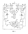
- the dryer of Figure 1 is composed of a pair of desiccant tanks I and II. These tanks are disposed vertically. Each tank contains a bed 1 of desiccant such as silica gel or activated alumina. Also provided in tanks I and 11 are desiccant fill and drain ports 8, 9 for draining and filling of desiccant in the tanks.
- each tank is a removable desiccant support screen 25 made of perforated metal cylinder, retaining the desiccant bed 1 in the tanks I and II. This acts to retain any desiccant particles that might otherwise be carried out from the bed 1 past the desiccant screen support 25, to keep the outlet valves 13, 14 and the remainder of the system clean of such particles.
- the inlet line 6 conducts influent gas containing moisture to be removed to the distributing manifold 7 containing inlet valves 10, 11 1 which control influent gas flow to tanks I and II.
- the manifold 7 also includes exhaust valves 17, 18, dump valve 19 and muffler 20, through which purge flow is vented to atmosphere.
- Lines 2, 3 and 4, 5 connect the two tanks at top and bottom, respectively, for introduction of influent gas from and for delivery of dry effluent gas, freed from moisture after having passed through the tanks, to the outlet manifold 12 containing outlet valves 13, 14 and purge flow valves 15, 16 for controlling purge flow and effluent flow to and from each tank.
- From outlet manifold 12 extends the dry gas effluent delivery line 26 for delivery of dried effluent gas to the system being supplied therewith.
- the line 26 there can be placed an outlet pressure gauge and a humidity sensor, but these are optional, and can be omitted.
- One of valves 10, 11 (the other being closed) directs the flow of influent gas to one of two inlet lines 2 and 3, one of lines 2, 3 always leading the influent gas to the top of each tank I, 11, and the other of lines 2, 3 according to exhaust valves 17, 18 (the other of the exhaust valves being closed) leading the purge flow of regenerating effluent gas to the exhaust valve 19 and muffler 20 for venting to atmosphere.
- exhaust valves 17, 18 (the other of the exhaust valves being closed) leading the purge flow of regenerating effluent gas to the exhaust valve 19 and muffler 20 for venting to atmosphere.
- the gas on the adsorption cycle proceeds by downflow through each tank.
- One of lines 4, 5 always lead effluent gas from the bottom of each tank I, II, and the other of lines 4, 5 according to the position of valves 10, 11 always leads purge flow of effluent gas to the bottom of each tank I, II for regeneration.
- the outlet valves 13, 14 are leaf-spring-loaded check valves opening according to differential pressure thereacross between lines 4, 5 and the outlet line 26.
- Valves 15, 16 are conventional ball check valves.
- Valves 10, 11, 17 and 18 are operated by the timer control, but valves 13, 14, 15, 16 are pressure operated, the lead-spring loaded disc or ball being opened or displaced on switching and start-up of on-stream forward flow in line 4, 5, with the other one of the leaf-spring valves 13, 14 and ball valves 15, 16' at such switching time moving against its seat, the valve 13 or 14 closing off the line leading to the chamber undergoing regeneration at reduced pressure, and thus directing main effluent flow to the outlet line 26, while purge flow proceeds via the ball check valve 15, 16 and thence via line 4 or 5 to the chamber I or II, now in the reverse direction, in upflow.
- the dryer has only four timer-actuated valves: inlet valves 10, 11 and exhaust valves 17, 18, all in the inlet manifold 7. All other valves are system differential-pressure actuated, and are thus automatic according to gas flow, as provided through the inlet manifold 7 via valves 10, 11, 17, 18.
- Each of the inlet valves 10, 11 is of the semiautomatic positive flow type, in that inlet air pressure differential in the normal flow direction will open the valve in the absence of timer-controlled gas pressure applied from lines 21, 22, respectively, according to the open or closed position of solenoid valves 51, 53, operated by the timer assembly.
- Each of the exhaust valves 17, 18 is of the opposite semiautomatic type, in that inlet air pressure differential in the normal flow direction keeps the valve closed in the absence of timer-controlled gas pressure applied from lines 23, 24, respectively, according to the open or closed position of solenoid valves 52, 54, operated by the timer assembly.
- exhaust of gas pressure in lines 21, 22, 23, 24 results in valves 10, 11 being open and valves 17, 18 closed. It is therefore up to the timer to actuate the closing of valves 10, 11 and the opening of valves 17, 18 for purge flow.
- only one of valves 10, 11 and only one of the valves 17, 18 is open at any given time.
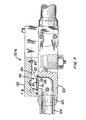
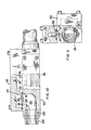
- the inlet valve 11 is best seen in Figure 4 (valve 10 is identical, but facing in the opposite direction) and comprises a tubular valve housing 30 with a central bore 31, within which reciprocates a valve piston 32.
- the inlet manifold housing 29 is provided with an inlet port 33 (connected to line 6) and an outlet port 34 (connected to line 3) interconnected by the through passage 35, which is a continuation of the bore 31 in housing 30.
- the valve passage 35 and outlet port 34 are in flow communication with the valve chamber 36, a reentrant portion 37 of which at the periphery of the bore 35 constitutes a valve seat, against which seats resilient seal ring 28, captured by the annular cap 38 and retained at the narrowed end of the piston 32 by the nut 39 and washer 40.
- the seal ring 28 Upon reciprocation of the piston against the valve seat 37, the seal ring 28 provides an effective seal, closing off the passage 35 and interrupting flow communication between the inlet 33 and outlet 34, and thus lines 6 and 3.
- the housing 30 is threaded into the chamber 36, which thus also serves as a socket.
- valve chamber 41 defined by an enlarged portion of the bore 31, and the cap 42 attached to the end of piston 32 slides within this chamber 41.
- the 0-ring seal 43 in recess 44 of the piston 32 provides a leak-tight seal with the bore 31, and thus there is no flow communication between the chambers 36, 41.
- U-cup seal 43' in recess 44' of cap 42 provides a leak-tight seal that precludes flow communication between chamber 41 and port 46.
- the outlet end of the chamber 41 is closed off by the cover 45, which threads into the housing, and limits the outward movement of the piston 32 and its cap 42.
- a port 46 Through the cover 45 is a port 46, which is in flow connection with line 22, through which from time to time the control timer applies gas pressure to the outer face of the cap 42 by opening valve 51.
- Such pressure has its origin in the dry gas effluent line 26, tapped via line 27' and filter 27.
- One of the valves 10, 11 is always in the open position while the other is held the closed position by timer-applied air pressure, so as to direct the influent gas to one of the two tanks I, II via influent lines 2, 3.
- gas pressure is always being applied to one of the valves 10, 11, via one of lines 21, 22, while the other line is open to the atmosphere, and therefore the valve remains open while gas pressure in passage 35 is above atmospheric, and closes when the force applied to cap 42 in chamber 41 is above the force applied to the piston 32 in passage 35.
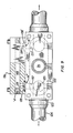
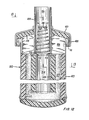
- the exhaust valve 18 best seen in Figure 5 is of a similar construction, with the difference that the pressure gas port opens onto the other face of the piston, and therefore serves to open the valve, instead of closing it, while the piston is spring-biased closed.
- the valve includes a tubular housing 50, with an inlet port 51, and an outlet port 52', and a flow passage 53 therebetween.
- the flow passage 53 is a continuation of the through bore 54, within which is mounted a reciprocable piston 55, spring-biased into the closed position shown in Figure 5 by the coil compression spring 56.
- the passage 53 opens into the piston chamber 57, a reentrant portion 58 of the wall of which at the periphery of the passage 53 constitutes a valve seat.
- the piston 55 has a seal ring 59 captured by the annular cap 60, and held firmly on the narrowed end of piston 55 against the annular cap by the screw nut 61, and washer 62.
- the seal ring 59 seals against the valve seat 58 with the piston in the closed position, as shown in Figure 5.
- the piston has a peripheral recess 63 within which is retained the 0-ring seal 64, forming a leak-tight seal against the walls of the bore, and preventing fluid communication between the piston chamber 57 and the piston chamber 65 at the other side of the cap portion 66 of the piston.
- the housing 50 is threaded into the open end of chamber 57, and thus attached to the inlet manifold housing 29.
- the coil spring 56 is retained at one end within the recess 67 of the cap 66, and at the other end by the reentrant portion 68 of the cover 69, which is threaded onto the housing 50, closing off the end of chamber 65.
- the cover 69 is locked against the housing 50 by the clamping ring 71, which is bolted onto the external face of the housing with the gasket 70 therebetween, by bolts 77.
- the piston 55 has a through bore 72 extending between passage 53 and chamber 65 and putting them in flow communication, and the cover 69 prevents the chamber 65 and passage 73 from communication with atmospheric pressure.
- the bore 72 narrows to capillary dimensions at the portion 74 opening into the passage 53.
- a third gas port 75 connecting with passage 76 opens into the chamber 65 on the other side of the cap 66, so that pressure applied there tends to drive piston 55 to the right.
- U-cup seals 65' in recesses 66' seal off the two parts of chambers 65 from each other.
- the back pressure acting on the opposite side of the cap 66 is limited in area due to the dimensions of the valve cover and recess 68, which offer a surface area less than that on the other side of the cap 66.
- the back pressure does not overcome the effect of pressure via the port 75, 76, and the valve remains in the open position in this situation.
- the outlet valve assemblies 13, 14 seen in Figures 6, 7 and 8 (only 13 is shown; 14 is identical, but on the opposite side of the housing) comprise leaf spring-loaded disks 130, best seen in Figure 7, acting as check valves, compelling unidirectional flow of dry effluent gas to the outlet, ball check valves 127 compelling unidirectional purge flow, and stem valve 93 controlling the amount of purge flow.
- the valve assembly comprises a housing 84 which shelters all these valves and as seen in Figure 1 constitutes an outlet line manifold.
- the leaf-spring valves 130 are a part of the valves 13, 14 controlling flow to the effluent gas line 26, and the ball check valves 127 are a part of the valves 15, 16 controlling purge flow communicated directly to whichever of lines 4, 5 leads to the low pressure chamber undergoing regeneration.
- Stem valve 93 controls effluent gas flow withdrawn from the effluent for purge flow regeneration.
- the valves 13, 14 open only when upstream pressure via line 4 or 5 from chamber 1 or 2 is greater than downstream pressure in the effluent line 26 or the other of lines 5 and 4 leading to the low pressure chamber being regenerated. At other times, they remain closed. Accordingly, they open only when the chamber before line 4 or 5 is on-stream for adsorption.
- the housing 122 has inlet port 123 receiving the line connection 124 (connected with line 4) communicating with flow passage 125 in the housing.
- the passage 125 leads directly to the cross passage 126, at each end of which is a leaf spring disk valve 130 allowing flow from passage 125 to passage 126, but not in the reverse direction.
- the leaf spring disc valve 130 has an inverted receptacle 120 defining a recess 78 with a valve plate 79 retained to the receptacle 120 by the rivet 80 and with an 0-ring 81 captured between the outer periphery of the plate 79 and the inner periphery of the receptacle 120 so as to form a leak-tight seal when the valve disk as shown in Figure 6 is retained against the valve seat 85 at the peripheral edge of the passage 125 where it joins passage 126.
- valve is retained in this position, as shown in Figure 7, by the leaf spring 82, one end of which is held in the wall of passage 126 by the screw 83, and the other end of which is retained by the rivet 80 against the exterior face of the receptacle 120, in a manner such that the spring 82 biases the valve disk against the seat.
- valve Upon a sufficient pressure differential across the valve disk between passages 125 and 126, due to high pressure in passage 4, as compared to downstream gas effluent pressure in passage 126 and line 26, exceeding the predetermined biasing force of the leaf spring 82, the valve is thrust away from the valve seat, opening the passages 125, 126 to flow of gas from the line 4 or 5 to the effluent gas line 26.
- valve 127 Unidirectional purge flow is ensured by the ball check valve 127, best seen in Figure 6. (The drawing show valve 16; valve 15 is identical at the other end.)
- This valve is housed in another portion 84 of the valve housing 122.
- the portion 84 has a through passage 85 in flow communication at one end via the passage 86 with the gas flow passage 125 of the housing 122.
- the ball check valve 127 Across the line of flow of passage 86 before passage 85 is the ball check valve 127, composed of a ball 87 movable towards and away from the valve seat 88 within the chamber 89.
- the ball check valve 16 as shown in Figure 6 is in the open position, which is its position when valve 13 is open. Since its passage 125 leads via port 123 and line connection 124 via the line 5 to chamber II, which is being regenerated, and therefore at lower pressure, the ball check valve assumes this position because the pressure in passages 85 and 86 exceeds the pressure in its passage 125, and thus the valve 16 in this position permits flow for purge purposes to line 5.
- the ball check valve 1 5 on the other side of the outlet manifold 12 is in the closed position, however, shown in dashed lines in Figure 6, because the pressure in its passage 125 exceeds the pressure in the passage 85, and thus purge flow is blocked from passage 86 between passages 125 and 85.
- passage 90 Also in flow communication with passage 85 is a passage 90, with an orifice plate 91 thereacross having a through orifice passage 92 restricting maximum flow in the passage 90 to that which can be accommodated by the orifice 92.
- This passage leads directly, as seen in Figure 8, to the effluent gas outlet passage 26 on the other side of the leaf spring valve 130.
- a variable position rotatable stem valve 93 (best seen in Figure 8) which at one end projects outside the housing 84, and is provided with gland nut 95 sealing the stem to the housing 84.
- the cap embraces the stem valve over a considerable reach, and at its inner portion 94 threads into the socket 96 of the housing 84.
- the passage 90 at the point where it meets the bore 96 has a dog-leg which is tapered at 97, thus receiving the conical tip of the valve in a tapered seal.
- Passage 90 is closed off when the stem 93 is rotated fully into the bore, but the valve can be retained at any position intermediate a fully opened and a fully closed position, because of the threaded fit, and in such position restricts the passage at 97 to an annulus between the exterior periphery of the valve and the wall of the passage, thus further restricting flow through the passage 90 to less than that permitted by the orifice 92, if desired.
- the dump valve has a tubular housing 100 with a through passage 101 leading at the upper end, as shown in Figure 12, from the inlet manifold 7 to a muffler 102 at the other end.
- the muffler 102 has a bowl portion 103 with a labyrinthine passage 104 extending down the center through tube 105, which is in flow communication with the end of tube 100 and concentric therewith, to the bottom of the bowl 103, whence it turns and continues as annular passage 109 up to the exhaust chamber 106, defined between the upper wall of the bowl 103, the outer wall of the tube 100, and baffle 107, attached to the tube 100 at one end, extending outwardly, and then turned so as to reach partway over the top of the bowl 103 as the shield 108.
- the walls of the tube 105, bowl 103, and baffle 107 are lined with sound- insulating material 110, such as, for example, a nonwoven mat of mineral wool or glass fibers, or plastic foam material such as polyurethane or polystyrene foam.
- sound- insulating material 110 such as, for example, a nonwoven mat of mineral wool or glass fibers, or plastic foam material such as polyurethane or polystyrene foam.
- a retaining plate 111 is attached thereto, for example, by welding, brazing or soldering, with a central aperture 112 communicating passages 101 and 104.
- the upper face of the plate 111 at the periphery of the aperture 112 constitutes a ledge 113, which serves as a support for one end of a conical coil compression spring 115.
- the spring extends concentrically through the passage 101 for a little over half the length of the tube 100.
- the final coil of the spring supports an orifice plate 116, the coil being captured in the peripheral recess 117 of the plate.
- An orifice 118 extends through the plate.
- the coil spring and orifice plate together constitute a variable shut-off valve which assumes an infinite number of positions between fully extended open and fully compressed closed position according to the pressure differential across the valve between passages 101 and 104.
- passage 104 is open to the atmosphere at the outlet passage 111 between the shield 108 and the bowl 103
- the coil spring 115 begins to be compressed, to a greater or lesser extent, according to magnitude of the pressure differential thereacross.
- the pressure differential exceeds a predetermined minimum, the spring is fully compressed, and the only opening for gas flow past the spring is via the orifice 118.
- the orifice 118 accordingly permits a small bleed flow at all times, even in the closed position of the valve. This reduces pressure in passage 101.
- the compression spring 115 gradually extends upwardly, and as it does so, spaces open between the coils thereof, which also permit flow of gas between passages 101 and 104, thus increasing the rate of flow from the upstream side of the valve and increasing the drain of gas, and thus increasing the rate of reduction of gas pressure and decreasing the pressure differential across the valve. Accordingly, the valve with the increasing speed continues to open out, and finally reaches the fully- open position shown in Figure 12.
- valves 10 and 18 are open, 11 and 17 closed, and the operation of the dryer proceeds as follows: wet gas influent at, for example, 8 kg/cm 2 and a flow rate of 86.6 m 3 /min saturated at 26.67°C enters through the inlet line 6, proceeds into the inlet manifold 7, passes the valve 10 (valve 11 being closed) and enters the top of the first tank I, and passes thence downwardly through the bed of desiccant 1 therein, for example, silica gel or activated alumina, to the bottom of the tank, and thence through line 4, valve 13 to the dry gas outlet line 26.
- wet gas influent at, for example, 8 kg/cm 2 and a flow rate of 86.6 m 3 /min saturated at 26.67°C enters through the inlet line 6
- proceeds into the inlet manifold 7 passes the valve 10 (valve 11 being closed) and enters the top of the first tank I, and passes thence downwardly through the bed of desiccant 1 therein, for example, si
- Effluent gas is delivered there at 7.65 kg/cm 2 dewpoint -40°C.
- the valve 15 is closed, under pressure differential across the ball 87 between passage 85 and 86, and prevents entry of dry gas into line 5 except via line 90, stem valve 93 and orifice 92.
- This metered portion of the dry gas effluent, 11.3 m 3 /min. is bled off into the line 5 while its pressure is reduced to atmospheric, and then passes through line 5 to the bottom of the second tank II, which is on the regeneration cycle.
- Purge flow passes upwardly through the desiccant bed 1, and emerges at the top into line 3, and thence passes through valve 18 to the dump valve 19 and through muffler 20, where it is vented to the atmosphere.
- the purge exhaust valves 17, 18 are so actuated by the fixed timer via valves 52, 54 and lines 23, 24 that they are opened only for the time necessary to complete regeneration of the desiccant. When this time has elapsed, they are shut off, and the regenerated tank II is then automatically and slowly repressurized with dry effluent gas via lines 90 and 5.
- Purge flow proceeds via line 4 to the bottom of tank I, which is on the regeneration cycle, and thence upwardly through the bed to the line 2, and thence through exhaust valve 17, dump valve 19, and muffler 12, where it is vented to the atmosphere.
- This cycle continues until the regeneration time cycle is completed, whereupon the fixed timer deactuates solenoid valve 54, and exhausts line 23, so that purge exhaust valve 17 closes.
- the line 4 slowly repressurizes tank I.
- tank II on the drying cycle until the fixed cycle time has elapsed, whereupon the fixed timer actuates solenoid valves 53, 52 and deactuates valve 51, which reverses valves 10, 11 and 18, and the cycle begins again.
- the drying cycle is carried out with gas at a super-atmospheric pressure, of the order of 2.05 to 25.5 kg/cm 2.
- the orifice 92 and stem valve 93 in the line 90 in combination with the purge exhaust valves 17, 18 and dump valve 19 ensure that the regeneration cycle is carried out at a pressure considerably reduced from that at which the adsorption cycle is effected.
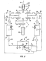
- the microprocessor-controlled dryer of Figure 2 is generally similar to that of Figure 1 in most respects, and therefore like reference numerals are used for like parts.
- the dryer is composed of a pair of desiccant tanks I and II, containing a bed 1 of desiccant such as silica gel or activated alumina. Also provided in tanks I and II are desiccant fill and drain ports 8, 9 for draining and filling of desiccant in the tanks.
- each tank is a removable desiccant support screen 25 made of perforated metal cylinder, retaining the desiccant bed 1 in the tanks I and II. This acts to retain any desiccant particles that might otherwise be carried out from the bed 1 past the desiccant screen support 25, to keep the outlet valves 13', 14' and the remainder of the system clean of such particles.
- the inlet line 6 includes a venturi 6a which has taps at its inlet and at its narrowest point at its center for differential pressure and flow measurement.
- any- other type of flow restriction can be used, such as an orifice nozzle, meter or paddle wheel.
- Flow rate can also be determined as a function of pressure drop across the desiccant bed 1 or across the inlet valves 10, 11.
- Lines 2, 3 and 4, 5 connect the two tanks at top and bottom, respectively, for introduction from the inlet line 6 of influent gas containing moisture to be removed via the distributing manifold 7 containing inlet valves 10, 11 and for delivery of dry effluent gas from the two tanks, freed from moisture after having passed through the dryer, to the outlet manifold 12 containing outlet valves 13' 14' and one pair of purge flow orifices 15' 16', for controlling purge flow and effluent flow to and from each tank.
- the manifold 7 also includes exhaust valves 17, 18, dump valve 19 and muffler 20, through which purge flow is vented to atmosphere.
- the line 6 conducts the moist influent gas from venturi 6a to the manifold 7 and the inlet valves 10, 11.
- One of valves 10, 11 directs the flow of influent gas to one of two inlet lines 2 and 3, one of lines 2, 3 always leading the influent gas to the top of one of tanks I, II, and the other of lines 2, 3 according to exhaust valves 17, 18 leading the purge flow of regenerating effluent gas to the exhaust valve 19 and muffler 20 venting to atmosphere.
- the gas proceeds by downflow through each tank.
- From outlet manifold 12 extends the dry gas effluent delivery line 26, for delivery of dried effluent gas to the system being supplied therewith.
- In the line 26 there can be placed an outlet pressure gauge and a humidity sensor, but these are optional, and can be omitted.
- valves 10, 11 According to the position of valves 10, 11 one of lines 4, 5 always leads dry effluent gas from the bottom of each tank I, II to the outlet line 26, and the other of lines 4, 5 always leads purge flow of effluent gas to the bottom of each tank I, II for regeneration.
- the outlet valves 13', 14' are leaf-spring loaded check valves opening according to differential pressure thereacross between lines 4, 5 and the outlet line 26.
- Valves 10, 11, 17 and 18 are pilot gas operated, controlled by the microprocessor, but valves 13', 14' are pressure-operated, the leaf-spring loaded disc being opened or displaced on switching and start up of on-stream forward flow in line 4, 5 while the other one of the leaf-spring valves 13', 14' at such switching time moving against the seat, valves 13' or 14' closing off the line leading to the chamber undergoing regeneration at reduced pressure, and thus directing dry gas effluent flow to the outlet line 26, while purge flow proceeds via orifices 15", 16" or 16", 15" to the chamber I or II, now in the reverse direction, in upflow.
- a pressure sensor P 3 and above valve 14' a second pressure sensor P 4 , and downstream thereof at outlet line 26 a temperature sensor T 2 .
- Pressure gauges P 3 , P 4 read off the pressure at the outlet valves 13', 14' and thus give the regeneration pressure in each tank as it is undergoing regeneration, while T 2 gives effluent gas temperature.
- the dryer has only four microprocessor- actuated valves: inlet valves 10, 11 and exhaust valves 17, 18, all in the inlet manifold 7. All other valves are system differential-pressure actuated, and are thus automatic according to gas flow, as provided through the inlet manifold via valves 10, 11, 17, 18.
- Each of the inlet valves 10, 11 is of the semiautomatic positive flow type, in that inlet air pressure differential in the normal flow direction will open the valve in the absence of microprocessor-controlled gas pressure applied from lines 21, 22 respectively according to the open or closed position of solenoid valves 51, 53, operated by the microprocessor.
- Each of the exhaust valves 17, 18 is of the opposite semiautomatic type in that inlet air pressure differential in the normal flow direction keeps the valve closed in the absence of microprocessor-controlled gas pressure applied from lines 23, 24, respectively, according to the open or closed position of solenoid valves 52, 54, operated by the microprocessor.
- exhaust of gas pressure in lines 21, 22, 23, 24 results in valves 10, 11 being open and valves 17, 18 closed. It is therefore up to the microprocessor to actuate the closing of valves 10, 11 and the opening of valves 17, 18 for purge flow.
- only one of valves 10, 11 and 17, 18 is open at any given time.
- valve 11 is best seen in Figure 4 (valve 10 is identical, but facing in the opposite direction) and reference is made to that description above.
- One of the valves 10, 11 is always in the open position while the other is held in the closed position by microprocessor-applied air pressure, so as to direct the influent gas to one of the two tanks I, II via influent lines 2, 3.
- gas pressure is always being applied to one of the valves 10, 11, via one of lines 21. 22, while the other line is open to the atmosphere, and therefore the valve remains open while gas pressure in passage 36 is above atmospheric, and closes when the force applied to cap 42 in chamber 41 is above the force applied to the force or piston 32 in chamber 36.
- exhaust valve 18 is best seen in Figure 5 (exhaust valve 17 is identical, facing in the opposite direction) and reference is made to that description, above.
- the exhaust valve is of a similar construction, with the difference that the pressure gas port opens onto the other face of the piston, and therefore serves to open the valve, instead of closing it, while the piston is spring-biased closed.
- the outlet valve assemblies 13', 14' are best seen in Figures 9, 10 and 11 (only 14' is shown; 13' is identical, but on the opposite side of the housing). These are similar to those shown in Figures 6, 7 and 8, and therefore like reference numerals are used for like parts.
- These valves comprise leaf spring-loaded disks 130, best seen in Figure 7, acting as check valves, compelling unidirectional dry effluent gas flow to the outlet. Orifices 15" and 16" control the amount of purge flow.
- the valve assembly comprises a housing 132 which shelters both these valves and, as seen in Figure 2, constitutes an outlet line manifold 12.
- the leaf spring valve 130 controls flow to the effluent gas line 26, and the orifices 15", 16" control purge flow communicated directly to whichever of lines 4, 5 leads to the low pressure chamber undergoing regeneration.
- the valves 13', 14' open only when upstream pressure via line 4 or 5 from chamber or II is greater than downstream pressure in the effluent line 26 or the other of lines 5 and 4 leading to the low pressure chamber being regenerated. At other times, they remain closed. Accordingly, they open only when the chamber before line 4 or 5 is on-stream for adsorption.
- the housing 132 has inlet port 123 receiving the line connection 124 (connected with line 4), communicating with flow passage 135 in the housing.
- the passage 125 leads directly to the cross passage 126 at each end of which is a leaf spring disk valve 130 allowing flow from passage 125 to passage 126, but not in the reverse direction.
- the leaf spring valve 130 has an inverted receptacle 120 defining a recess 78 with a valve plate 79 retained to the receptacle 120 by the rivet 80 and with an 0-ring 81 captured between the outer periphery of the plate 79 and the inner periphery of the receptacle 120 so as to form a leak-tight seal when the valve disk as shown in Figure 10 is retained against the valve seat 135 at the peripheral edge of the passage 125 where it joins passage 126.
- valve is retained in this position, as shown in Figure 10, by the leaf spring 82, one end of which is held to the wall of passage 126 by the screw 83, and the other end of which is retained by the rivet 80 against the exterior face of the receptacle 120, in a manner such that the spring 82 biases the valve disk against the seal.
- valve Upon a sufficient pressure differential across the valve disk between passage 125 and 126, due to high pressure in passage 4, as compared to downstream gas effluent pressure in passage 126 and line 26, exceeding the predetermined biasing force of the leaf spring 82, the valve is thrust away from the valve seat, opening the passages 125, 126 to flow of gas from the line 4 to 5 to the effluent gas line 26.
- passage 137 Also in flow communication with passage 125 in housing 136 is a passage 137 with an orifice plate 138 thereacross having a through orifice passage 139 restricting maximum flow in the passage 137 to that which can be accommodated by the orifice 139 and thereby reducing pressure beyond the orifice.
- the passage 137 leads directly as seen in Figure 9 to the purge flow passage 140 on the other side of the orifice 139.
- passage 140 At each end of passage 140 is a plug 141, closing it off, so that flow through the orifice passage 139 proceeds along passage 140 and then through the orifice 139', passage 137', and passage 125 via port 123 into line 5, undergoing further pressure reduction as it does so, chamber II being at atmospheric pressure when exhaust valve 18 and dump valve 19 are open. Flow proceeds in this way so long as pressure in line 5 and chamber II is below line pressure in line 4 and passage 125.
- the dump valve is best seen in Figures 12 and 13, and has been described above.
- valves 10 and 18 are open, 11 and 17 closed, and the operation of the dryer proceeds as follows: wet gas influent at, for example, 8 kg/cm 2 and a flow rate of 86.6 m 3 /min saturated at 26.67°C enters through the inlet line 6, passes the venturi 6a and valve 10 (valve 11 being closed) and enters the top of the first tank I, and passes thence downwardly through the bed of desiccant 1 therein, for example, silica gel or activated alumina, to the bottom of the tank, and thence through filter 25 and opening line 4, valve 130 (13') and proceeding via line 16 to the dry gas outlet line 26.
- Effluent gas is delivered there at 7.65 kg/cm 2 and 75 m 3 /min dewpoint -40°C.
- the valve 14' (the second valve 130) prevents entry of dry gas into line 5 except via passages 137, 137', orifices 139, 139', and passage 140.
- This metered portion of the dry gas effluent 11.3 m 3 /min is bled off through the line 5, its pressure having been reduced to atmospheric on the other side of the orifice 139', and then passes to the bottom of the second tank II, which is on the regeneration cycle.
- Purge flow passes upwardly through the desiccant bed 1, and emerges at the top into line 3, and thence passes through valve 18, to dump valve 19, and muffler 20, where it is vented to the atmosphere.
- purge exhaust valves 17, 18 are so actuated by the microprocessor that they are opened only for the time necessary to complete regeneration of the desiccant. When this time has elapsed, they are shut off, and the regenerated tank II is then automatically and slowly repressurized via line 5.
- Purge flow proceeds via line 4 to the bottom of tank I, which is on the regeneration cycle, and thence upwardly through the bed to the line 2 and thence through valve 17, valve 19, and muffler 20 where it is vented to the atmosphere.
- This cycle continues until the regeneration time cycle is completed, whereupon the microprocessor closes purge exhaust valve 17.
- line 4 slowly repressurizes tank I.
- tank II on the drying cycle until the microprocessor determined or fixed cycle time has elapsed, whereupon the microprocessor reverses valves 10, 11 and the cycle begins again.
- the drying cycle is carried out with gas at a super-atmospheric pressure, of the order of 2.05 to 25.5 k g /cm.
- the orifices ensure that the regeneration cycle is carried out at a pressure considerably reduced from that at which the adsorption cycle is effected.
- the electric circuit connections for the microprocessor are shown in Figure 3.
- the microprocessor includes a data acquisition module, for collecting data from the temperature and pressure transducers, an input/output module for input and output data receipt and control, the microprocessor, and RAM and ROM memory banks for storing the information used in the control function.
- the inlet pressure sensor P also can be used to ascertain flow rate, and the purge and regeneration pressure sensors P 3 , P are connected to pressure transducers, which are connected to the data acquisition module, which is directly connected with the input and output module.
- the input/output module is also connected with the microprocessor, and this is connected to the memory banks.
- the inlet temperature sensor T, the outlet temperature sensor T 2 and the purge temperature sensor T 3 are connected to the temperature transducers, which in turn are connected to the data acquisition module.
- an atmospheric pressure sensor In addition to these sensors, which are essential, there can also be included an outlet pressure sensor P 5 , all connected to the transducers and data acquisition module.
- the alarm system which is optional, can detect humidity via the humidity sensor H, a failure in any of the inlet manifold valves 10, 11, 17, 18, and failure in any of the sensors, whereupon the microprocessor can signal an alarm.
- the alarm system is connected to the input/output module.
- microprocessor control system shown in Figure 3 operates as follows:
- the microprocessor orders data from the input/output module and performs calculations on the data based upon the programs contained in the ROM memory. Temporary numbers used in the computations are stored in the RAM memory, or "scratch" pad.
- the microprocessor sends signals through the input/output module to control the system solenoid valve relays.
- the inlet differential pressure, Ap indicates the inlet velocity. This plus P, and T, yields the inlet flow rate in SCFM.
- P 3 , or P 4 and T 3 knowing the purge orifice size and gas, are used to calculate the actual purge flow rate in SCFM.
- the regeneration pressure and temperature P 3 or P 4 and T Z are used to determine the amount of water which can be removed by the purge.
- T 2 less T indicates the amounts of humidity in the inlet air.
- T 2 may be sensed in the desiccant beds using T 2 ' and T 2 " in tanks I and II.
- the pressure transducers P 3 , P 4 are omitted, and replaced by a single pressure transducer P 6 in the exhaust line before the dump valve 19 and following valves 17, 18.
- the temperature transducers remain the same, and also the pressure transducers P,, P 2 .
- the pressure transducers P 6 determines regeneration pressure at the outlet from the tank undergoing regeneration, in lieu of the inlet, as in the system of Figure 1.
- the microprocessor accurately senses the dryer operating conditions, precisely calculates the required purge flow necessary to thoroughly regenerate a desiccant bed based on the sensed operating conditions, and controls both the dryer cycling time, on a fixed time basis, and the regeneration time based on the calculated purge flow required. As a result, minimal purge gas is consumed and the dryer is more economical to operate than any other type of dehydration system for almost all applications.
- the microprocessor may also display the paramount operating data on visual indicators. It also monitors the dryer for correct operation. In the event of a fault condition, the microprocessor diagnoses the fault and displays a flashing coded message on an alarm indicator. Thus, the microprocessor assists in maintaining the dryer system and facilitates troubleshooting.
- the various inlet and outlet purge and regeneration sensors have multiple functions, according to which bed is on the adsorption cycle, and which bed is on the regeneration cycle, since a given sensor on one cycle will sense inlet temperature, for example, while on the other cycle it will sense outlet temperature. Which sensor senses which function in which cycle is apparent from this portion of the disclosure.
- the dryer systems of the invention can be used with any type of sorbent adapted to adsorb moisture from gases.
- Activated carbon, alumina, silica gel, magnesia, various metal oxides, clays, Fuller's earth, bone char, and Mobilbeads, and like moisture-adsorbing compounds can be used as the desiccant.
- This class of materials includes zeolites, both naturally-occurring and synthetic, the pores in which may vary in diameter from the order of several Angstrom units to from 1.2 nm to 1.5 nm or more. Chabasite and analcite are representative natural zeolites that can be used. Synthetic zeolites that can be used include those described in U.S. patents Nos. 2,442,191 and 2,306,610. All of these materials are well known as desiccants, and detailed descriptions thereof will be found in the literature.
- the dryers described and shown in the drawings are all adapted for purge flow regeneration with the purge passing in counterflow to the wet gas influent.
- This is the most efficient way of utilizing a desiccant bed.
- the moisture content of the desiccant progressively decreases, and normally the least amount of moisture will have been adsorbed at the outlet end of the bed.
- the purge flow be introduced at the outlet end, then the moisture present there, although it may be in a small amount, will be removed by the purge flow and brought downwards the wetter end of the bed.
- the bed is progressively regenerated from the outlet end, and all the moisture is carried for the least possible distance through the bed before it emerges at the inlet end.
- a two-bed heatless dryer of the type shown in Figure 2 having two desiccant beds 1.270 mm long and 210 mm in diameter, each bed . containing 34 kg of activated alumina, was used to dry air at 70% relative humidity, 19.4°C to 21 °C and 6.6 kg/cm 2 inlet pressure.
- the superficial flow velocity of the air was 55 feet per minute.
- sorbents useful for the removal of moisture from air can also be used, preferentially to adsorb one or more gas components from a mixture thereof, such as activated carbon, glass wool, adsorbent cotton, metal oxides and clays such as attapulgite and bentonite, Fuller's earth, bone char and natural and synthetic zeolites.
- the zeolites are particularly effective for the removal of nitrogen, hydrogen and olefins, such as ethylene or propylene, from a mixture with propane and higher paraffin hydrocarbons, or butene or higher olefins.
- the selectivity of a zeolite is dependent upon the pore size of the material.
- the available literature shows the selective adsorptivity of the available zeolites, so that the selection of a material for a particular purpose is rather simple and forms no part of the instant invention.
Landscapes
- Chemical & Material Sciences (AREA)
- Engineering & Computer Science (AREA)
- Analytical Chemistry (AREA)
- General Chemical & Material Sciences (AREA)
- Oil, Petroleum & Natural Gas (AREA)
- Chemical Kinetics & Catalysis (AREA)
- Separation Of Gases By Adsorption (AREA)
- Drying Of Gases (AREA)
- Organic Low-Molecular-Weight Compounds And Preparation Thereof (AREA)
- Treatment Of Liquids With Adsorbents In General (AREA)
- Sampling And Sample Adjustment (AREA)
- Separation By Low-Temperature Treatments (AREA)
- Hooks, Suction Cups, And Attachment By Adhesive Means (AREA)
- Spinning Or Twisting Of Yarns (AREA)
- Supplying Secondary Fuel Or The Like To Fuel, Air Or Fuel-Air Mixtures (AREA)
- Superconductors And Manufacturing Methods Therefor (AREA)
Priority Applications (3)
| Application Number | Priority Date | Filing Date | Title |
|---|---|---|---|
| AT82106809T ATE24417T1 (de) | 1978-10-26 | 1979-10-19 | Vorrichtung zur fraktionierung von gas zur reduktion der konzentration von einem oder mehreren ersten gasen in einer mischung mit einem zweiten gas. |
| DE8282106809T DE2967645D1 (en) | 1978-10-26 | 1979-10-19 | Gas fractionating apparatus for reducing the concentration of one or more first gases in a mixture thereof with a second gas |
| AT79104053T ATE11740T1 (de) | 1978-10-26 | 1979-10-19 | Kontrollsystem fuer adsorber mit abwaerts- oder aufwaertsfluss. |
Applications Claiming Priority (2)
| Application Number | Priority Date | Filing Date | Title |
|---|---|---|---|
| US05/954,812 US4247311A (en) | 1978-10-26 | 1978-10-26 | Downflow or upflow adsorbent fractionator flow control system |
| US954812 | 2001-09-17 |
Related Child Applications (2)
| Application Number | Title | Priority Date | Filing Date |
|---|---|---|---|
| EP82106809A Division-Into EP0072463B1 (en) | 1978-10-26 | 1979-10-19 | Gas fractionating apparatus for reducing the concentration of one or more first gases in a mixture thereof with a second gas |
| EP82106809A Division EP0072463B1 (en) | 1978-10-26 | 1979-10-19 | Gas fractionating apparatus for reducing the concentration of one or more first gases in a mixture thereof with a second gas |
Publications (2)
| Publication Number | Publication Date |
|---|---|
| EP0010704A1 EP0010704A1 (en) | 1980-05-14 |
| EP0010704B1 true EP0010704B1 (en) | 1985-02-13 |
Family
ID=25495960
Family Applications (2)
| Application Number | Title | Priority Date | Filing Date |
|---|---|---|---|
| EP79104053A Expired EP0010704B1 (en) | 1978-10-26 | 1979-10-19 | Downflow or upflow adsorbent fractionator flow control system |
| EP82106809A Expired EP0072463B1 (en) | 1978-10-26 | 1979-10-19 | Gas fractionating apparatus for reducing the concentration of one or more first gases in a mixture thereof with a second gas |
Family Applications After (1)
| Application Number | Title | Priority Date | Filing Date |
|---|---|---|---|
| EP82106809A Expired EP0072463B1 (en) | 1978-10-26 | 1979-10-19 | Gas fractionating apparatus for reducing the concentration of one or more first gases in a mixture thereof with a second gas |
Country Status (14)
| Country | Link |
|---|---|
| US (1) | US4247311A (es) |
| EP (2) | EP0010704B1 (es) |
| JP (2) | JPS5559824A (es) |
| AT (2) | ATE11740T1 (es) |
| AU (1) | AU523648B2 (es) |
| BR (1) | BR7906952A (es) |
| CA (3) | CA1130219A (es) |
| DE (2) | DE2967645D1 (es) |
| DK (1) | DK150635C (es) |
| ES (2) | ES485365A1 (es) |
| FI (1) | FI793332A (es) |
| NO (2) | NO157487C (es) |
| PT (1) | PT70378A (es) |
| ZA (1) | ZA795701B (es) |
Families Citing this family (89)
| Publication number | Priority date | Publication date | Assignee | Title |
|---|---|---|---|---|
| US4322223A (en) * | 1979-03-30 | 1982-03-30 | Pall Corporation | Adsorbent fractionators with electronic sequence timer cycle control and process |
| DE3173496D1 (en) * | 1980-08-18 | 1986-02-27 | Normalair Garrett Ltd | Molecular sieve type gas separation systems |
| US4392870A (en) * | 1981-05-11 | 1983-07-12 | Sun Oil Company Of Pennsylvania | Vapor recovery unit performance test analyzer and method |
| ATE30122T1 (de) * | 1982-02-25 | 1987-10-15 | Pall Corp | Fraktionierer fuer adsorbierte gase mit automatischer temperaturgesteuerter zykluskontrolle und verfahren. |
| US4516424A (en) * | 1982-07-09 | 1985-05-14 | Hudson Oxygen Therapy Sales Company | Oxygen concentrator monitor and regulation assembly |
| US4627860A (en) * | 1982-07-09 | 1986-12-09 | Hudson Oxygen Therapy Sales Company | Oxygen concentrator and test apparatus |
| US4648888A (en) * | 1982-07-09 | 1987-03-10 | Hudson Oxygen Therapy Sales Co. | Oxygen concentrator |
| US4472177A (en) * | 1982-09-09 | 1984-09-18 | Air Products And Chemicals, Inc. | Control system and method for air fractionation by vacuum swing adsorption |
| US4546442A (en) * | 1982-11-24 | 1985-10-08 | Pall Corporation | Microcomputer control system for desiccant dryer |
| US4525183A (en) * | 1982-11-26 | 1985-06-25 | Pall Corporation | Valves for desiccant dryers |
| US4479815A (en) * | 1983-03-09 | 1984-10-30 | Pall Corporation | Pneumatic controller and alarm for adsorbent fractionaters, particularly dessicant dryers |
| DE3310842A1 (de) * | 1983-03-25 | 1984-10-04 | Zander Aufbereitungstechnik GmbH, 4300 Essen | Adsorptionstrockner |
| US4491459A (en) * | 1983-05-04 | 1985-01-01 | Pinkerton Charles J | Portable oxygen enrichment and concentration system |
| JPS6017231U (ja) * | 1983-07-12 | 1985-02-05 | カヤバ工業株式会社 | デシケ−タ装置 |
| ZA846511B (en) * | 1983-08-25 | 1985-04-24 | Pall Corp | Natural gas sweetner and dehydrator without atmospheric acid gas discharge |
| US4539019A (en) * | 1983-09-29 | 1985-09-03 | Air Products & Chemicals, Inc. | Control system for air fractionation by selective adsorption |
| US4512781A (en) * | 1983-11-14 | 1985-04-23 | Pittsburgh Brass Manufacturing Company | Shuttle valves and system for fluid control |
| US4559065A (en) * | 1984-03-15 | 1985-12-17 | Wilkerson Corporation | Twin tower gas fractionation apparatus |
| US4631073A (en) * | 1984-03-15 | 1986-12-23 | Wilkerson Corporation | Method and apparatus for theadsorptive fractionation of gases |
| US4687573A (en) * | 1984-08-13 | 1987-08-18 | Pall Corporation | Sorbing apparatus |
| US4605425A (en) * | 1985-05-06 | 1986-08-12 | Pall Corporation | Heaterless dryer having variable cycle |
| US4718020A (en) * | 1985-05-30 | 1988-01-05 | Pall Corporation | Fault recovery procedure for heat-reactivated dryer |
| JPS6369529U (es) * | 1986-10-27 | 1988-05-10 | ||
| US4941894A (en) * | 1988-04-12 | 1990-07-17 | Hankison Division Of Hansen, Inc. | Gas drying or fractioning apparatus and method |
| DE8810997U1 (es) * | 1988-08-31 | 1988-10-20 | Stanelle, Karl-Heinz, 7129 Gueglingen, De | |
| US4927434A (en) * | 1988-12-16 | 1990-05-22 | Pall Corporation | Gas component extraction |
| US4891051A (en) * | 1989-01-11 | 1990-01-02 | Roanoke College | System for decontaminating compressed gas |
| CN1032120C (zh) * | 1991-08-14 | 1996-06-26 | 成都华西化工研究所 | 变压吸附程序控制操纵装置 |
| US5346535A (en) * | 1991-08-23 | 1994-09-13 | Engelhard Corporation | Use of crystalline molecular sieves containing charged octahedral sites in removing volatile organic compounds from a mixture of the same |
| EP0561029A1 (de) * | 1992-03-20 | 1993-09-22 | FREY-AUFBEREITUNGSTECHNIK GmbH | Verfahren und Vorrichtung zur diskontinuierlichen Trocknung von Luft |
| GB2286135A (en) * | 1994-01-26 | 1995-08-09 | Boc Group Plc | Pressure swing adsorption apparatus |
| US5906672A (en) * | 1996-06-14 | 1999-05-25 | Invacare Corporation | Closed-loop feedback control for oxygen concentrator |
| US5917135A (en) * | 1996-06-14 | 1999-06-29 | Invacare Corporation | Gas concentration sensor and control for oxygen concentrator utilizing gas concentration sensor |
| US5930910A (en) * | 1997-11-26 | 1999-08-03 | Westinghouse Air Brake Company | Purge tube with flapper valve for desiccant containing air drier |
| US5901464A (en) * | 1997-11-26 | 1999-05-11 | Westinghouse Air Brake Company | E-1 twin tower air dryer for an air compressor unit |
| US5901459A (en) * | 1997-11-26 | 1999-05-11 | Westinghouse Air Brake Company | Shuttle mechanism for twin tower air dryer system |
| US5989313A (en) * | 1997-12-19 | 1999-11-23 | Praxair Technology, Inc. | Method for operation of an air prepurifier which takes into account inlet air conditions |
| US6014820A (en) * | 1998-02-02 | 2000-01-18 | Westinghouse Air Brake Company | Shuttle valve for twin tower air dryer |
| US6152163A (en) * | 1998-04-23 | 2000-11-28 | United Dominion Industries, Inc. | Switching valve for multi-chamber adsorbent air and gas fractionation system |
| US6117207A (en) * | 1998-05-06 | 2000-09-12 | Miserlis; Constantine | Process for recovering metals and other chemical components from spent catalysts |
| US6026587A (en) * | 1998-07-10 | 2000-02-22 | Westinghouse Air Brake Company | Intercooler blowdown valve |
| SE9901071L (sv) * | 1999-03-24 | 2000-09-25 | Haldex Brake Prod Ab | Sätt och anordning vid en enkammarlufttorkare |
| AU5466400A (en) | 1999-06-04 | 2000-12-28 | Flair Corporation | Rotating drum adsorber process and system |
| US6604406B1 (en) * | 1999-06-23 | 2003-08-12 | Sandia Corporation | Human portable preconcentrator system |
| US6221130B1 (en) * | 1999-08-09 | 2001-04-24 | Cooper Turbocompressor, Inc. | Method of compressing and drying a gas and apparatus for use therein |
| FR2798075B1 (fr) * | 1999-09-03 | 2001-11-09 | Air Liquide | Conduite d'un systeme de purification d'air a regeneration thermique |
| US6375722B1 (en) * | 2000-08-22 | 2002-04-23 | Henderson Engineering Co., Inc. | Heat of compression dryer |
| GB0119149D0 (en) * | 2001-08-06 | 2001-09-26 | Wabco Automotive Uk Ltd | Vehicle air braking system |
| KR20030049279A (ko) * | 2001-12-14 | 2003-06-25 | 전덕철 | 흡착식 에어 드라이어용 흡착열 천이 감지 시스템 |
| US6755895B2 (en) * | 2002-04-09 | 2004-06-29 | H2Gen Innovations, Inc. | Method and apparatus for pressure swing adsorption |
| JP3990295B2 (ja) * | 2003-01-14 | 2007-10-10 | シーケーディ株式会社 | 消音器、圧縮気体の消音方法、除湿装置 |
| US7135059B2 (en) * | 2003-10-07 | 2006-11-14 | Inogen, Inc. | Portable gas fractionalization system |
| US20050072426A1 (en) * | 2003-10-07 | 2005-04-07 | Deane Geoffrey Frank | Portable gas fractionalization system |
| US20050072423A1 (en) * | 2003-10-07 | 2005-04-07 | Deane Geoffrey Frank | Portable gas fractionalization system |
| EP1677895A2 (en) | 2003-10-07 | 2006-07-12 | Inogen, Inc. | Portable gas fractionalization system |
| US7066985B2 (en) * | 2003-10-07 | 2006-06-27 | Inogen, Inc. | Portable gas fractionalization system |
| US7115152B2 (en) * | 2004-01-12 | 2006-10-03 | Friday David K | Four bed regenerable filter system |
| FR2865554B1 (fr) * | 2004-01-28 | 2006-05-05 | Air Liquide | Procede de commande d'une installation de traitement d'un gaz |
| JP4487600B2 (ja) | 2004-03-05 | 2010-06-23 | 株式会社ジェイテクト | 流量制御装置 |
| US7201003B2 (en) * | 2004-03-11 | 2007-04-10 | General Electric Company | Magnet vent assembly apparatus |
| DE102004026650B4 (de) * | 2004-06-01 | 2007-11-29 | DRäGER AEROSPACE GMBH | Verfahren zum Betreiben einer Luftzerlegungsanlage zur Gewinnung von Sauerstoff an Bord eines Flugzeugs |
| BE1016145A3 (nl) * | 2004-08-02 | 2006-04-04 | Atlas Copco Airpower Nv | Verbeterde compressorinrichting. |
| US7243679B2 (en) * | 2004-12-20 | 2007-07-17 | Flair Corporation | Adsorbent fractionator directional flow control valve assembly apparatus and method |
| US7814934B2 (en) * | 2004-12-20 | 2010-10-19 | Flair Corporation | Adsorbent fractionator directional flow control valve assembly apparatus and method |
| US20060196356A1 (en) * | 2005-02-04 | 2006-09-07 | Henderson Terry D | Single tower gas dryer with flowing desiccant stream |
| US20060196361A1 (en) * | 2005-02-04 | 2006-09-07 | Henderson Terry D | Single tower gas dryer with flowing desiccant stream |
| US7686870B1 (en) | 2005-12-29 | 2010-03-30 | Inogen, Inc. | Expandable product rate portable gas fractionalization system |
| ITTO20070237A1 (it) * | 2007-04-03 | 2008-10-04 | Faiveley Transport Italia Spa | Gruppo di essiccazione ad adsorbimento con gestione ottimizzata della portata e/o della fase di rigenerazione e impianto di trattamento aria comprendente un tale gruppo |
| EP2144687B1 (en) | 2007-04-20 | 2015-06-10 | Invacare Corporation | Product gas concentrator and method associated therewith |
| US7846237B2 (en) * | 2008-04-21 | 2010-12-07 | Air Products And Chemicals, Inc. | Cyclical swing adsorption processes |
| US9120050B2 (en) | 2008-04-21 | 2015-09-01 | Invacare Corporation | Product gas concentrator utilizing vacuum swing adsorption and method associated therewith |
| JP2010042331A (ja) * | 2008-08-11 | 2010-02-25 | Kyuchaku Gijutsu Kogyo Kk | 圧力スイング吸着法によるオゾン製造装置を搭載したバラスト水処理装置 |
| US9600001B2 (en) * | 2012-01-13 | 2017-03-21 | Perkinelmer Health Sciences, Inc. | Devices, systems and methods for purging and loading sorbent tubes |
| NZ722551A (en) | 2012-03-09 | 2018-01-26 | Invacare Corp | System and method for concentrating gas |
| US9067174B2 (en) | 2012-03-09 | 2015-06-30 | Invacare Corporation | System and method for concentrating gas |
| US9266053B2 (en) | 2012-06-18 | 2016-02-23 | Invacare Corporation | System and method for concentrating gas |
| FR2988011B1 (fr) * | 2012-03-14 | 2014-03-28 | Mil S | Installation pour une production d'air medical |
| CN103028312A (zh) * | 2012-12-27 | 2013-04-10 | 重庆联合机器制造有限公司 | 高压干燥装置气动阀控制装置 |
| AU2015376127B2 (en) * | 2015-01-07 | 2019-10-17 | Norgren Limited | Dual filter for moisture removal from a fluid flow |
| AU2016335133B2 (en) * | 2015-10-04 | 2019-03-14 | New York Air Brake, LLC | Air dryer control using humidity |
| EP3402586B1 (en) | 2016-03-23 | 2021-06-30 | New York Air Brake LLC | Adsorption drying unit and method of operating the same |
| BE1024244B9 (nl) * | 2016-04-08 | 2018-02-05 | Atlas Copco Airpower Nv | Een droger voor het drogen van persgas en werkwijze voor het regenereren van een droogmateriaal vervat in de droger. |
| US10786777B2 (en) * | 2016-06-10 | 2020-09-29 | Schroeder Industries, Llc | Compact desiccant air breather with unidirectional air flow |
| CN108686242A (zh) * | 2018-05-15 | 2018-10-23 | 安徽沛愉包装科技有限公司 | 自动压力差保持装置 |
| FR3096278B1 (fr) * | 2019-05-23 | 2021-09-10 | Air Liquide | Procédé de réglage d’une unité de production d’oxygène par comparaison des pressions différentielles caractéristiques des différents adsorbeurs |
| BE1027959B1 (nl) * | 2020-01-02 | 2021-08-05 | Atlas Copco Airpower Nv | Werkwijze voor het drogen van samengeperst gas |
| EP4182054A1 (en) | 2020-07-16 | 2023-05-24 | Invacare Corporation | System and method for concentrating gas |
| WO2022015909A1 (en) | 2020-07-16 | 2022-01-20 | Invacare Corporation | System and method for concentrating gas |
| JP2024014450A (ja) * | 2022-07-22 | 2024-02-01 | 三菱重工業株式会社 | 除湿装置、水素製造設備及び除湿装置の運転方法 |
Citations (2)
| Publication number | Priority date | Publication date | Assignee | Title |
|---|---|---|---|---|
| US3472000A (en) * | 1968-04-29 | 1969-10-14 | Westinghouse Air Brake Co | Air dryer and purge control unit |
| EP0009139A1 (en) * | 1978-08-31 | 1980-04-02 | Pall Corporation | Heatless adsorbent fractionators with microprocessor cycle control and process |
Family Cites Families (29)
| Publication number | Priority date | Publication date | Assignee | Title |
|---|---|---|---|---|
| FR897238A (fr) * | 1940-05-18 | 1945-03-15 | Oesterreichische Magnesit Ag | Procédé pour la séparation de mélanges de gaz ou de gaz et vapeurs en circulation |
| US2306610A (en) * | 1941-02-24 | 1942-12-29 | Barrer Richard Maling | Fractionation of mixtures of hydrocarbons |
| US2442191A (en) * | 1944-05-26 | 1948-05-25 | Standard Oil Dev Co | Synthetic adsorbent for separating hydrocarbons |
| GB677150A (en) * | 1948-11-25 | 1952-08-13 | Linde Eismasch Ag | Improvements in or relating to the purification of gas mixtures |
| US2800197A (en) * | 1955-12-09 | 1957-07-23 | Nat Distillers Chem Corp | Chlorine recovery |
| US2944627A (en) * | 1958-02-12 | 1960-07-12 | Exxon Research Engineering Co | Method and apparatus for fractionating gaseous mixtures by adsorption |
| US3080693A (en) * | 1958-10-29 | 1963-03-12 | Westinghouse Air Brake Co | Automatic cleaning apparatus for filters in compressed air systems |
| US3324631A (en) * | 1963-11-07 | 1967-06-13 | Robertshaw Controls Co | Air drying means |
| US3365861A (en) * | 1964-04-09 | 1968-01-30 | Abcor Inc | Gas fractionating apparatus |
| US3287883A (en) * | 1964-05-27 | 1966-11-29 | Honeywell Inc | Gas drying system |
| GB1144692A (en) * | 1965-03-12 | 1969-03-05 | Pall Corp | Gas drier with automatic cycle control and process |
| GB1168102A (en) * | 1966-07-13 | 1969-10-22 | Lloyd And Hillman Ltd | A Timing and Switching Valve Apparatus and an Apparatus for Processing Air or other Gas including the same |
| US3561464A (en) * | 1968-10-22 | 1971-02-09 | Honeywell Inc | Fluidic control apparatus |
| US3659399A (en) * | 1970-06-29 | 1972-05-02 | Air Technologies Inc | Fractionation by adsorption |
| US3778967A (en) * | 1971-01-18 | 1973-12-18 | Air Technologies Inc | Apparatus and process for the fractionation by the adsorption of a compressed gas |
| GB1350811A (en) * | 1971-06-29 | 1974-04-24 | Iv Pressure Controllers Ltd | Pressure control devices |
| JPS4919167A (es) * | 1972-06-16 | 1974-02-20 | ||
| JPS4936536U (es) * | 1972-07-04 | 1974-04-01 | ||
| US3775946A (en) * | 1972-10-13 | 1973-12-04 | Howe Baker Eng | Adsorption control |
| US3923479A (en) * | 1973-09-21 | 1975-12-02 | Westinghouse Air Brake Co | Multiple filter apparatus |
| US3880616A (en) * | 1973-11-19 | 1975-04-29 | Bendix Corp | Respiratory support system |
| GB1513377A (en) * | 1974-09-12 | 1978-06-07 | British Ceca Co | Absorber control systems |
| US4038050A (en) * | 1974-11-27 | 1977-07-26 | W. R. Grace & Co. | Electrical sensing and regenerating system for molecular sieve driers |
| DE2523079B2 (de) * | 1975-05-24 | 1977-04-07 | Böwe Böhler & Weber KG Maschinenfabrik, 8900 Augsburg | Vorrichtung zur adsorptiven entfernung von loesemitteldaempfen aus einem luftstrom |
| JPS5334664A (en) * | 1976-09-13 | 1978-03-31 | Hitachi Metals Ltd | Bend forming process |
| US4127395A (en) * | 1976-10-18 | 1978-11-28 | Pall Corporation | Adsorbent fractionator with fail-safe automatic cycle control and process |
| JPS5375170A (en) * | 1976-12-15 | 1978-07-04 | Chiyuukiyou Seiki Kk | Dehumidication or gas separation apparatus with heat separator |
| US4101298A (en) * | 1977-04-05 | 1978-07-18 | The Bendix Corporation | Pressure cycling control for fluid separator mechanism |
| AU5079679A (en) * | 1978-09-15 | 1980-03-20 | Wilke & Co. | Lithographic master base material |
-
1978
- 1978-10-26 US US05/954,812 patent/US4247311A/en not_active Expired - Lifetime
-
1979
- 1979-10-19 EP EP79104053A patent/EP0010704B1/en not_active Expired
- 1979-10-19 AT AT79104053T patent/ATE11740T1/de not_active IP Right Cessation
- 1979-10-19 EP EP82106809A patent/EP0072463B1/en not_active Expired
- 1979-10-19 DE DE8282106809T patent/DE2967645D1/de not_active Expired
- 1979-10-19 AT AT82106809T patent/ATE24417T1/de not_active IP Right Cessation
- 1979-10-19 DE DE7979104053T patent/DE2967389D1/de not_active Expired
- 1979-10-24 AU AU52120/79A patent/AU523648B2/en not_active Ceased
- 1979-10-25 ES ES485365A patent/ES485365A1/es not_active Expired
- 1979-10-25 FI FI793332A patent/FI793332A/fi not_active Application Discontinuation
- 1979-10-25 ZA ZA00795701A patent/ZA795701B/xx unknown
- 1979-10-25 DK DK450679A patent/DK150635C/da not_active IP Right Cessation
- 1979-10-25 CA CA338,431A patent/CA1130219A/en not_active Expired
- 1979-10-25 NO NO793427A patent/NO157487C/no unknown
- 1979-10-26 BR BR7906952A patent/BR7906952A/pt unknown
- 1979-10-26 JP JP13862079A patent/JPS5559824A/ja active Granted
- 1979-10-26 PT PT70378A patent/PT70378A/pt unknown
-
1980
- 1980-03-18 ES ES489665A patent/ES8100097A1/es not_active Expired
-
1981
- 1981-11-06 CA CA389,664A patent/CA1127558A/en not_active Expired
- 1981-11-06 CA CA389,665A patent/CA1127559A/en not_active Expired
-
1982
- 1982-12-28 JP JP57234895A patent/JPS6012084B2/ja not_active Expired
-
1984
- 1984-06-20 NO NO84842487A patent/NO161540C/no unknown
Patent Citations (2)
| Publication number | Priority date | Publication date | Assignee | Title |
|---|---|---|---|---|
| US3472000A (en) * | 1968-04-29 | 1969-10-14 | Westinghouse Air Brake Co | Air dryer and purge control unit |
| EP0009139A1 (en) * | 1978-08-31 | 1980-04-02 | Pall Corporation | Heatless adsorbent fractionators with microprocessor cycle control and process |
Also Published As
| Publication number | Publication date |
|---|---|
| ES485365A1 (es) | 1980-09-01 |
| NO793427L (no) | 1980-04-29 |
| DK150635B (da) | 1987-05-04 |
| ATE11740T1 (de) | 1985-02-15 |
| AU523648B2 (en) | 1982-08-05 |
| CA1127558A (en) | 1982-07-13 |
| EP0010704A1 (en) | 1980-05-14 |
| JPS58196824A (ja) | 1983-11-16 |
| EP0072463A3 (en) | 1983-11-09 |
| DE2967645D1 (en) | 1987-02-05 |
| AU5212079A (en) | 1980-05-01 |
| DK150635C (da) | 1987-11-16 |
| FI793332A (fi) | 1980-04-27 |
| JPS6012084B2 (ja) | 1985-03-29 |
| CA1130219A (en) | 1982-08-24 |
| ES489665A0 (es) | 1980-11-01 |
| BR7906952A (pt) | 1980-06-24 |
| ATE24417T1 (de) | 1987-01-15 |
| US4247311A (en) | 1981-01-27 |
| CA1127559A (en) | 1982-07-13 |
| DK450679A (da) | 1980-04-27 |
| JPS6259616B2 (es) | 1987-12-11 |
| EP0072463A2 (en) | 1983-02-23 |
| NO157487B (no) | 1987-12-21 |
| EP0072463B1 (en) | 1986-12-30 |
| DE2967389D1 (en) | 1985-03-28 |
| NO161540B (no) | 1989-05-22 |
| PT70378A (en) | 1979-11-01 |
| NO842487L (no) | 1980-04-29 |
| ZA795701B (en) | 1980-11-26 |
| ES8100097A1 (es) | 1980-11-01 |
| NO157487C (no) | 1988-03-30 |
| JPS5559824A (en) | 1980-05-06 |
| NO161540C (no) | 1989-08-30 |
Similar Documents
| Publication | Publication Date | Title |
|---|---|---|
| EP0010704B1 (en) | Downflow or upflow adsorbent fractionator flow control system | |
| US4197095A (en) | Heatless adsorbent fractionators with microprocessor cycle control and process | |
| US4832711A (en) | Adsorbent fractionator with automatic temperature-sensing cycle control and process | |
| US4127395A (en) | Adsorbent fractionator with fail-safe automatic cycle control and process | |
| US4162146A (en) | Multi-chamber adsorbent gas fractionator with non-jamming effluent flow control valve | |
| US3448561A (en) | Adsorbent fractionator with automatic cycle control and process | |
| US4631073A (en) | Method and apparatus for theadsorptive fractionation of gases | |
| US4322223A (en) | Adsorbent fractionators with electronic sequence timer cycle control and process | |
| EP0168336B1 (en) | Twin tower gas fractionation apparatus | |
| US4205967A (en) | Adsorbent fractionator with system gas powered cycle control and process | |
| US3800507A (en) | Low pressure air dehydrator | |
| EP0088905B1 (en) | Adsorbent fractionator with automatic temperature-sensing cycle control and process | |
| JPH0143569B2 (es) | ||
| EP0000521A1 (en) | A process and an apparatus for fractionating gas mixtures | |
| KR940006396B1 (ko) | 압력스윙식건조제 재생방식건조기용 가스건조사이클의 소요시간 한정제어 시스템과 소요시간을 제한, 변화시키는 방법 및 가스성분 추출장치 | |
| GB2035124A (en) | Adsorbent fractionator with influent gas control of the adsorbent cycle duration | |
| JPH0351449B2 (es) |
Legal Events
| Date | Code | Title | Description |
|---|---|---|---|
| PUAI | Public reference made under article 153(3) epc to a published international application that has entered the european phase |
Free format text: ORIGINAL CODE: 0009012 |
|
| AK | Designated contracting states |
Designated state(s): AT BE CH DE FR GB IT NL SE |
|
| 17P | Request for examination filed |
Effective date: 19801030 |
|
| ITF | It: translation for a ep patent filed |
Owner name: BARZANO' E ZANARDO ROMA S.P.A. |
|
| GRAA | (expected) grant |
Free format text: ORIGINAL CODE: 0009210 |
|
| AK | Designated contracting states |
Designated state(s): AT BE CH DE FR GB IT NL SE |
|
| REF | Corresponds to: |
Ref document number: 11740 Country of ref document: AT Date of ref document: 19850215 Kind code of ref document: T |
|
| REF | Corresponds to: |
Ref document number: 2967389 Country of ref document: DE Date of ref document: 19850328 |
|
| ET | Fr: translation filed | ||
| PLBE | No opposition filed within time limit |
Free format text: ORIGINAL CODE: 0009261 |
|
| STAA | Information on the status of an ep patent application or granted ep patent |
Free format text: STATUS: NO OPPOSITION FILED WITHIN TIME LIMIT |
|
| 26N | No opposition filed | ||
| PG25 | Lapsed in a contracting state [announced via postgrant information from national office to epo] |
Ref country code: BE Effective date: 19861031 |
|
| BERE | Be: lapsed |
Owner name: PALL CORP. Effective date: 19861031 |
|
| ITTA | It: last paid annual fee | ||
| PGFP | Annual fee paid to national office [announced via postgrant information from national office to epo] |
Ref country code: AT Payment date: 19931007 Year of fee payment: 15 |
|
| PGFP | Annual fee paid to national office [announced via postgrant information from national office to epo] |
Ref country code: GB Payment date: 19931011 Year of fee payment: 15 Ref country code: FR Payment date: 19931011 Year of fee payment: 15 |
|
| PGFP | Annual fee paid to national office [announced via postgrant information from national office to epo] |
Ref country code: CH Payment date: 19931013 Year of fee payment: 15 |
|
| PGFP | Annual fee paid to national office [announced via postgrant information from national office to epo] |
Ref country code: SE Payment date: 19931015 Year of fee payment: 15 |
|
| PGFP | Annual fee paid to national office [announced via postgrant information from national office to epo] |
Ref country code: DE Payment date: 19931021 Year of fee payment: 15 |
|
| PGFP | Annual fee paid to national office [announced via postgrant information from national office to epo] |
Ref country code: NL Payment date: 19931031 Year of fee payment: 15 |
|
| PG25 | Lapsed in a contracting state [announced via postgrant information from national office to epo] |
Ref country code: GB Effective date: 19941019 Ref country code: AT Effective date: 19941019 |
|
| PG25 | Lapsed in a contracting state [announced via postgrant information from national office to epo] |
Ref country code: SE Effective date: 19941020 |
|
| PG25 | Lapsed in a contracting state [announced via postgrant information from national office to epo] |
Ref country code: CH Effective date: 19941031 |
|
| EAL | Se: european patent in force in sweden |
Ref document number: 79104053.8 |
|
| PG25 | Lapsed in a contracting state [announced via postgrant information from national office to epo] |
Ref country code: NL Effective date: 19950501 |
|
| GBPC | Gb: european patent ceased through non-payment of renewal fee |
Effective date: 19941019 |
|
| NLV4 | Nl: lapsed or anulled due to non-payment of the annual fee | ||
| PG25 | Lapsed in a contracting state [announced via postgrant information from national office to epo] |
Ref country code: FR Effective date: 19950630 |
|
| REG | Reference to a national code |
Ref country code: CH Ref legal event code: PL |
|
| PG25 | Lapsed in a contracting state [announced via postgrant information from national office to epo] |
Ref country code: DE Effective date: 19950701 |
|
| EUG | Se: european patent has lapsed |
Ref document number: 79104053.8 |
|
| REG | Reference to a national code |
Ref country code: FR Ref legal event code: ST |