EP0010528B1 - Vorrichtung zum Vereinzeln und Zuführen V-förmiger Metallschienen - Google Patents
Vorrichtung zum Vereinzeln und Zuführen V-förmiger Metallschienen Download PDFInfo
- Publication number
- EP0010528B1 EP0010528B1 EP79830035A EP79830035A EP0010528B1 EP 0010528 B1 EP0010528 B1 EP 0010528B1 EP 79830035 A EP79830035 A EP 79830035A EP 79830035 A EP79830035 A EP 79830035A EP 0010528 B1 EP0010528 B1 EP 0010528B1
- Authority
- EP
- European Patent Office
- Prior art keywords
- strip
- strips
- limit stops
- lowermost
- stack
- Prior art date
- Legal status (The legal status is an assumption and is not a legal conclusion. Google has not performed a legal analysis and makes no representation as to the accuracy of the status listed.)
- Expired
Links
Images


Classifications
-
- B—PERFORMING OPERATIONS; TRANSPORTING
- B42—BOOKBINDING; ALBUMS; FILES; SPECIAL PRINTED MATTER
- B42B—PERMANENTLY ATTACHING TOGETHER SHEETS, QUIRES OR SIGNATURES OR PERMANENTLY ATTACHING OBJECTS THERETO
- B42B5/00—Permanently attaching together sheets, quires or signatures otherwise than by stitching
-
- B—PERFORMING OPERATIONS; TRANSPORTING
- B65—CONVEYING; PACKING; STORING; HANDLING THIN OR FILAMENTARY MATERIAL
- B65G—TRANSPORT OR STORAGE DEVICES, e.g. CONVEYORS FOR LOADING OR TIPPING, SHOP CONVEYOR SYSTEMS OR PNEUMATIC TUBE CONVEYORS
- B65G59/00—De-stacking of articles
- B65G59/10—De-stacking nested articles
- B65G59/105—De-stacking nested articles by means of reciprocating escapement-like mechanisms
-
- Y—GENERAL TAGGING OF NEW TECHNOLOGICAL DEVELOPMENTS; GENERAL TAGGING OF CROSS-SECTIONAL TECHNOLOGIES SPANNING OVER SEVERAL SECTIONS OF THE IPC; TECHNICAL SUBJECTS COVERED BY FORMER USPC CROSS-REFERENCE ART COLLECTIONS [XRACs] AND DIGESTS
- Y10—TECHNICAL SUBJECTS COVERED BY FORMER USPC
- Y10T—TECHNICAL SUBJECTS COVERED BY FORMER US CLASSIFICATION
- Y10T29/00—Metal working
- Y10T29/53—Means to assemble or disassemble
- Y10T29/53709—Overedge assembling means
- Y10T29/53787—Binding or covering
- Y10T29/53791—Edge binding
Definitions
- the present invention relates to an apparatus designed to take first - from a bundle or a pile - and then feed downstream, individual metal strips in the shape of a "V", intended especially for the retention or the 'assembly of printed matter or the like, these printed matter or the like being inserted into the opening of the V, after which the strip is crushed using a special machine, of the press type.
- the strips must be presented at the downstream station, in this case the pressing machine, according to a very precise arrangement and orientation, in order to avoid the need to correct or adjust their position by hand.
- a device which performs the picking and feeding of the listels using a magnetic field to separate the listels from a package or stack of these articles.
- the operation of such a device is only satisfactory if the effort required to lift the strips from one another is low enough, that is to say, when the strips are wide open and that 'They affect an L-shaped configuration. Consequently, this apparatus of the known technique is absolutely not in a condition to operate with "V" shaped strips which come within the scope of the present invention.
- the object of the present invention is to propose an apparatus capable of carrying out in an automatic and reliable manner said operations of separation of the "V" shaped listels from the packets or stacks of these listels and, then, the one by one transfer of the appropriately arranged and oriented listels, to downstream processing stations, in particular, to a pressing machine.
- the invention also aims to provide an apparatus of the above type and characteristics, in which said operations are carried out using particularly simple and economical mechanical operator means and such that they allow rapid adaptation of the apparatus to listels of different formats.
- this device comprises: a magazine for receiving a packet or stack of listels in which the listels are nested one inside the other and arranged with the top of the V facing down; one or more end-of-travel stops to support the stack by the last strip from below; a pair of conical points situated longitudinally with respect to the end of the listels and whose axis coincides longitudinally with the hollow or spacing defined between the tops of the last and penultimate listels; means for controlling coordinated movements, on the one hand retraction or retraction in the inactive position of the end-of-travel stops, on the other hand for advancing the points between the last and penultimate strips until the separation of the last listel of the stack while ensuring the support of the rest of the stack; means for controlling coordinated movements of return to the active position and return to the inactive position of the stops and the spikes respectively; and means for taking the strip thus separated and for routing it to further processing.
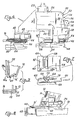
- the illustrated apparatus comprises, on a suitable support frame, generally indicated by 10 and which may be of any suitable structure, a pair of guide rails or parallel spaced slides 12 (only one of which has been shown in the drawings), these slides delimiting an internal housing shaped as a "U” 14 (FIGS. 2 and 3) in which the ends of metal strips 16 shaped like a "V" are retained, these being stacked -that is to say inserted or boxed into each other-with the vertices of the "V” slightly spaced due to the curvature deriving from said conformation in "V", as is essentially illustrated in FIG. 3.
- a suitable support frame generally indicated by 10 and which may be of any suitable structure
- a pair of guide rails or parallel spaced slides 12 delimiting an internal housing shaped as a "U” 14 (FIGS. 2 and 3) in which the ends of metal strips 16 shaped like a "V" are retained, these being stacked -that is to say inserted or boxed into each other-with the vertices
- listels can have, and generally have, an asymmetrical configuration according to which one branch of the V is longer than the other, and, because of their conformation, which delimits an angle as shown on the drawings or even smaller, these list They are very tightly packed together, so that to separate a listel 16 'from the stack of listels 16, some force must be exerted between said listel 16' and the last of the listels 16 remaining in the stack.
- the slides 12 delimit housings 14 shaped as a "U" and placed opposite one another, in which housings the stack of strips is free to slide down under the effect of the dead weight, by means of an appropriate inclination of said slides 12, which, according to the example illustrated, have a substantially sub-vertical arrangement, but in any case form an angle different from 0 relative to the vertical, which makes it possible to guarantee the support of the listels, at any time, on one of the sides of the housing 14 and thus to have a fixed reference point for the games of the listel separation system, a system which operates with great precision, as will be seen below.
- the slides 12 are mounted so as to be able to move horizontally on supports 18, by means of bearings 18 ′ and, jointly with the means which control the separation of the individual strips, these slides can be adjusted, for example by means of a conventional device using a nut 20, to adapt to strips of different lengths, which gives the machine, in an advantageous manner, very great application flexibility.
- the stack of strips 16 is inserted into the slides 12, the latter being suitably adjusted according to the length of the strips and the stack descends by gravity along said slides until it comes to stop against the supports, or end stops. stroke 22, which are advantageously arranged near the ends of the stacked strips, so as to ensure an exact positioning, in the vertical direction, of said strips and, in particular that of these strips which is placed last.
- the detachment operation of the latter list is carried out, according to the invention, by coordinated movements of said end-of-travel stops 22 and of a pair of conical points 24, which penetrate into the hollow or spaces which delimit between them the last and penultimate of the listels in the stack. Thanks to their conicity, said points thus exert a force tending to separate the last listel, over a distance which is sufficient to completely detach it from the listel placed above, while supporting the rest of the stack.
- the end of travel stops 22 are mounted on a sliding plate 26, which is driven by an alternating rectilinear movement determined by one or more motor means 28, constituted, for example, by cylinder-piston aggregates acting under the effect of a command, the end-of-travel stops 22 being, moreover, capable of moving longitudinally, at the same time as the slides 12, to guarantee at all times the presence of these stops in the vicinity of the ends of the strips, as mentioned more high.
- the movable element 26 laterally compotes, in a manner also adjustable in the horizontal direction, parallel to the listel, a cam 30 whose profile 32 is spanned by a cam follower roller 34 which, for its part, is mounted on the end d 'A lever 36 pivoting about a vertical axis 38 forming part of a support block 40.
- This block is itself adjustable in a longitudinal direction to the strips 16 to allow adaptation to strips of different lengths.
- the end of the lever 36 which is opposite the roller 34 relative to the pivot 38 has a face 42 which acts on the rounded head of a rod 46 axially movable in a pad 48 supported by the block 40 and carrying the tip 24. What has just been explained is illustrated in particular in FIGS. 4, 5 and 6 where it can also be noted that the rod 46 is biased by a spring 50 in the direction which makes the point 24 move away from the strips 16 so constantly maintaining the roller 34 pressing on the profile 32 of the cam 30.
- Said profile 32 has a first ascending part 52 which causes a similar displacement of the points 24, in order to cause the latter to be inserted exactly in the hollow or spacing which delimit between them the last and penultimate listels of the stack, and this while supporting said stack except the last strip without, however, forcibly tightening the latter strip against the stops 22.
- the profile 32 of the cam 30 has a bearing 54 parallel to the movement of the plate 26, this bearing 54 determining the maintenance of the tips 24 in said partially inserted position, with support of the stack of listels with the exception of the last during a subsequent movement of backward movement of the stops 22 beyond the support position of the last strip 16 '.
- the last listel of the stack would be free to separate from it, but it is however held in place by the significant friction force determined by the current embellishment condition of the listels.
- the profile 32 of the cam 30 has another ascending part 56 which, the movement of the plate 26 continuing in the X direction, determines a subsequent displacement of the tips 24 between the last and penultimate listels. Thanks to an appropriate conical conformation of the points 24, this displacement forces the last strip 16 'to separate completely from the stack to fall down under the effect of the force of gravity.
- the reverse-opposite movement of the plate 26 causes an inverse sequence to the movements just described. During this reverse sequence, there is partial recoil of the points 24, which however also ensure the support of the stack of strips 16, while the stops 22 advance until they are placed below said stack, after which the the points 24 are brought into the inactive position of FIG. 4 and the stack of listels 16 descends a little bit until they bear against the stops 22, which brings the hollow or spacing between the last and penultimate strips to line up with the axis of the tips 24, the system then being ready for a new detachment operation.
- the housing 58 is delimited by walls 64, 66 inclined up and down and back, that is to say towards the plate 26, so as to force the strip 16 'to take a determined position, which is in practice a support position by its longest side, both during the insertion of the strip into the housing 58 and during the subsequent displacement of said housing 58-in concert with the bars 60, 62-displacement having place during the movement of the plate 26 back in its rest condition, illustrated in FIG. 4.
- This displacement determines a translation of the housing 58 in the direction Y orthogonal to the major axis of the listel, until the latter is brought into abutment on a feed conveyor means, such as for example the conveyor belt 68 (FIG.
- this belt moves continuously parallel to the long axis of the strip 16 ', to drive the latter out of the guide housing 58, by passing it below a jumper connecting member 70 (FIG. 7) which allows the bars 60, 62 to be made integral with one another, on the expulsion or unloading side of the strip 16 '.
- the conveyor belt 68 brings said strip to a downstream work station, for example a pressing machine which comprises, suitably positioned above the belt 68 and below a pressing member, a stop element by which the listel is retained for the time which is necessary for the operator to insert therein the forms to be assembled and to close the listel on these forms.
- a pressing machine which comprises, suitably positioned above the belt 68 and below a pressing member, a stop element by which the listel is retained for the time which is necessary for the operator to insert therein the forms to be assembled and to close the listel on these forms.
Landscapes
- Engineering & Computer Science (AREA)
- Textile Engineering (AREA)
- Auxiliary Devices For And Details Of Packaging Control (AREA)
- Sheets, Magazines, And Separation Thereof (AREA)
- Forming Counted Batches (AREA)
Claims (16)
Applications Claiming Priority (2)
| Application Number | Priority Date | Filing Date | Title |
|---|---|---|---|
| IT28745/78A IT1099904B (it) | 1978-10-13 | 1978-10-13 | Apparecchiatura per il prelievo e l'alimentazione di listelli metallici sagomati a v. |
| IT2874578 | 1978-10-13 |
Publications (3)
| Publication Number | Publication Date |
|---|---|
| EP0010528A2 EP0010528A2 (de) | 1980-04-30 |
| EP0010528A3 EP0010528A3 (en) | 1980-05-14 |
| EP0010528B1 true EP0010528B1 (de) | 1982-06-23 |
Family
ID=11224108
Family Applications (1)
| Application Number | Title | Priority Date | Filing Date |
|---|---|---|---|
| EP79830035A Expired EP0010528B1 (de) | 1978-10-13 | 1979-10-02 | Vorrichtung zum Vereinzeln und Zuführen V-förmiger Metallschienen |
Country Status (4)
| Country | Link |
|---|---|
| US (1) | US4298302A (de) |
| EP (1) | EP0010528B1 (de) |
| DE (1) | DE2963177D1 (de) |
| IT (1) | IT1099904B (de) |
Families Citing this family (1)
| Publication number | Priority date | Publication date | Assignee | Title |
|---|---|---|---|---|
| FR2619053B1 (fr) * | 1987-08-06 | 1990-01-05 | Guilhon Jean Claude | Dispositif d'alimentation automatique pour une machine de reliure a baguette sertie |
Family Cites Families (9)
| Publication number | Priority date | Publication date | Assignee | Title |
|---|---|---|---|---|
| US2974828A (en) * | 1958-04-16 | 1961-03-14 | Diamond National Corp | Vertical chute dispenser |
| GB1056050A (en) * | 1964-05-06 | 1967-01-25 | George Pulman & Sons Ltd | Improvements in and relating to binding leaves |
| US3513758A (en) * | 1965-08-13 | 1970-05-26 | Leonora Mining & Milling Co | Apparatus for taking,developing,compiling,and binding a series of photographs |
| US3468455A (en) * | 1967-11-14 | 1969-09-23 | Continental Can Co | Carton dispenser machine |
| US3477592A (en) * | 1968-03-27 | 1969-11-11 | Packaging Corp America | Denester |
| US3520046A (en) * | 1968-03-29 | 1970-07-14 | United Carr Inc | Automatic machine for attaching fasteners to a workpiece |
| US3542243A (en) * | 1968-10-02 | 1970-11-24 | Illinois Tool Works | Tray denesting device |
| US3701440A (en) * | 1969-06-20 | 1972-10-31 | Continental Can Co | Egg carton denester machine |
| GB1443821A (en) * | 1973-02-13 | 1976-07-28 | Ka Duk Lam | Sheet material fastening |
-
1978
- 1978-10-13 IT IT28745/78A patent/IT1099904B/it active
-
1979
- 1979-10-01 US US06/081,085 patent/US4298302A/en not_active Expired - Lifetime
- 1979-10-02 EP EP79830035A patent/EP0010528B1/de not_active Expired
- 1979-10-02 DE DE7979830035T patent/DE2963177D1/de not_active Expired
Also Published As
| Publication number | Publication date |
|---|---|
| EP0010528A3 (en) | 1980-05-14 |
| DE2963177D1 (en) | 1982-08-12 |
| IT7828745A0 (it) | 1978-10-13 |
| EP0010528A2 (de) | 1980-04-30 |
| US4298302A (en) | 1981-11-03 |
| IT1099904B (it) | 1985-09-28 |
Similar Documents
| Publication | Publication Date | Title |
|---|---|---|
| EP0281484B1 (de) | Verfahren zur Regelung des Ausmasses eines Matrizensets für Zuschnitte; Matrizenset | |
| FR2499039A1 (fr) | Dispositif pour introduire des paquets de feuilles dans une machine les travaillant | |
| EP2086841B1 (de) | Maschine für den transfer von zuschnitten für pappkartons | |
| FR2537957A1 (fr) | Dispositif de prise et d'entrainement de feuilles pour prendre, transporter et deposer un materiau en feuille | |
| FR2907100A1 (fr) | Installation d'emballage et de conditionnement. | |
| EP0248700B1 (de) | Verpackungsmaschine für "amerikanische" Schachteln | |
| EP0451592B1 (de) | Verfahren und Vorrichtung zum Bilden von Stapeln von der Oberseite eines Stapels von Blättern in einer Maschine zur Herstellung von Verpackungen | |
| EP1073603B1 (de) | Vorrichtung zum stapeln und übergeben von gedruckten signaturen in form von sätzen | |
| CH633761A5 (fr) | Dispositif pour empiler des objets plats, notamment des decoupes de boites pliantes. | |
| EP1369213B1 (de) | Vorrichtung zur Trennung Befestigungspunkte, die gestapelte Kartonbogen verbinden | |
| FR2584686A1 (fr) | Manipulateur de feuilles de papier applique a un appareil d'enlevement et de fourniture de feuilles de papier. | |
| CH607979A5 (en) | Device for handling stackable articles | |
| CH620170A5 (de) | ||
| EP0389393A1 (de) | Vorrichtung zum automatischen Anbringen von Etiketten auf Kartons und Paletten | |
| FR2508016A1 (fr) | Dispositif pour prelever des pieces a travailler d'une pile | |
| EP0451568A1 (de) | Maschine zum Bearbeiten von Platten oder Blattelementen ausgerüstet mit einer Vorrichtung zum Evakuieren der Frontausscheidung zum Herstellen von Verpackungen | |
| EP0010528B1 (de) | Vorrichtung zum Vereinzeln und Zuführen V-förmiger Metallschienen | |
| FR2654068A1 (fr) | Appareil d'alimentation de flans plans individuels pour des machines de conditionnement de produits dans des etuis du type a couvercle articule. | |
| EP0252936B1 (de) | Vorrichtung zum abheben von bogenpaketen, insbesondere von papier, von stapeln | |
| FR2812281A1 (fr) | Dispositif de chargement et/ou de dechargement de support de pile et poste de chargement et/ou dechargement correspondant | |
| EP3820265B1 (de) | Verfahren und vorrichtung zum schneiden eines radialen elektronischen bauteils | |
| FR2646620A1 (fr) | Dispositif de chargement et de dechargement de caissettes avec des objets plats, du genre enveloppes de courrier | |
| FR2690637A1 (fr) | Installation de manutention pour le transport de flans d'une machine de découpage à un dispositif d'empilage. | |
| FR2573401A1 (fr) | Procede d'empilage de couches horizontales superposees d'objets sur une palette et installation pour la mise en oeuvre de ce procede | |
| FR2688205A1 (fr) | Systeme de manipulation d'objets notamment pour machine de tri automatique de courrier. |
Legal Events
| Date | Code | Title | Description |
|---|---|---|---|
| PUAI | Public reference made under article 153(3) epc to a published international application that has entered the european phase |
Free format text: ORIGINAL CODE: 0009012 |
|
| PUAL | Search report despatched |
Free format text: ORIGINAL CODE: 0009013 |
|
| AK | Designated contracting states |
Designated state(s): BE CH DE FR GB NL |
|
| AK | Designated contracting states |
Designated state(s): BE CH DE FR GB NL |
|
| 17P | Request for examination filed |
Effective date: 19800929 |
|
| GRAA | (expected) grant |
Free format text: ORIGINAL CODE: 0009210 |
|
| AK | Designated contracting states |
Designated state(s): BE CH DE FR GB NL |
|
| REF | Corresponds to: |
Ref document number: 2963177 Country of ref document: DE Date of ref document: 19820812 |
|
| PGFP | Annual fee paid to national office [announced via postgrant information from national office to epo] |
Ref country code: CH Payment date: 19830826 Year of fee payment: 5 |
|
| PGFP | Annual fee paid to national office [announced via postgrant information from national office to epo] |
Ref country code: BE Payment date: 19830831 Year of fee payment: 5 |
|
| PGFP | Annual fee paid to national office [announced via postgrant information from national office to epo] |
Ref country code: FR Payment date: 19831003 Year of fee payment: 5 |
|
| PGFP | Annual fee paid to national office [announced via postgrant information from national office to epo] |
Ref country code: DE Payment date: 19831006 Year of fee payment: 5 |
|
| PGFP | Annual fee paid to national office [announced via postgrant information from national office to epo] |
Ref country code: NL Payment date: 19831031 Year of fee payment: 5 |
|
| PG25 | Lapsed in a contracting state [announced via postgrant information from national office to epo] |
Ref country code: CH Effective date: 19841031 Ref country code: BE Effective date: 19841031 |
|
| BERE | Be: lapsed |
Owner name: AMIA S.A.S. DI ALLIEVI ADOLFO & C. Effective date: 19841002 |
|
| PG25 | Lapsed in a contracting state [announced via postgrant information from national office to epo] |
Ref country code: NL Effective date: 19850501 |
|
| GBPC | Gb: european patent ceased through non-payment of renewal fee | ||
| NLV4 | Nl: lapsed or anulled due to non-payment of the annual fee | ||
| PG25 | Lapsed in a contracting state [announced via postgrant information from national office to epo] |
Ref country code: FR Free format text: LAPSE BECAUSE OF NON-PAYMENT OF DUE FEES Effective date: 19850628 |
|
| REG | Reference to a national code |
Ref country code: CH Ref legal event code: PL |
|
| PG25 | Lapsed in a contracting state [announced via postgrant information from national office to epo] |
Ref country code: DE Effective date: 19850702 |
|
| REG | Reference to a national code |
Ref country code: FR Ref legal event code: ST |
|
| PG25 | Lapsed in a contracting state [announced via postgrant information from national office to epo] |
Ref country code: GB Effective date: 19881118 |
|
| PLBE | No opposition filed within time limit |
Free format text: ORIGINAL CODE: 0009261 |
|
| STAA | Information on the status of an ep patent application or granted ep patent |
Free format text: STATUS: NO OPPOSITION FILED WITHIN TIME LIMIT |