EP0010528B1 - Device for separating and feeding v-shaped metallic strips - Google Patents
Device for separating and feeding v-shaped metallic strips Download PDFInfo
- Publication number
- EP0010528B1 EP0010528B1 EP79830035A EP79830035A EP0010528B1 EP 0010528 B1 EP0010528 B1 EP 0010528B1 EP 79830035 A EP79830035 A EP 79830035A EP 79830035 A EP79830035 A EP 79830035A EP 0010528 B1 EP0010528 B1 EP 0010528B1
- Authority
- EP
- European Patent Office
- Prior art keywords
- strip
- strips
- limit stops
- lowermost
- stack
- Prior art date
- Legal status (The legal status is an assumption and is not a legal conclusion. Google has not performed a legal analysis and makes no representation as to the accuracy of the status listed.)
- Expired
Links
Images


Classifications
-
- B—PERFORMING OPERATIONS; TRANSPORTING
- B42—BOOKBINDING; ALBUMS; FILES; SPECIAL PRINTED MATTER
- B42B—PERMANENTLY ATTACHING TOGETHER SHEETS, QUIRES OR SIGNATURES OR PERMANENTLY ATTACHING OBJECTS THERETO
- B42B5/00—Permanently attaching together sheets, quires or signatures otherwise than by stitching
-
- B—PERFORMING OPERATIONS; TRANSPORTING
- B65—CONVEYING; PACKING; STORING; HANDLING THIN OR FILAMENTARY MATERIAL
- B65G—TRANSPORT OR STORAGE DEVICES, e.g. CONVEYORS FOR LOADING OR TIPPING, SHOP CONVEYOR SYSTEMS OR PNEUMATIC TUBE CONVEYORS
- B65G59/00—De-stacking of articles
- B65G59/10—De-stacking nested articles
- B65G59/105—De-stacking nested articles by means of reciprocating escapement-like mechanisms
-
- Y—GENERAL TAGGING OF NEW TECHNOLOGICAL DEVELOPMENTS; GENERAL TAGGING OF CROSS-SECTIONAL TECHNOLOGIES SPANNING OVER SEVERAL SECTIONS OF THE IPC; TECHNICAL SUBJECTS COVERED BY FORMER USPC CROSS-REFERENCE ART COLLECTIONS [XRACs] AND DIGESTS
- Y10—TECHNICAL SUBJECTS COVERED BY FORMER USPC
- Y10T—TECHNICAL SUBJECTS COVERED BY FORMER US CLASSIFICATION
- Y10T29/00—Metal working
- Y10T29/53—Means to assemble or disassemble
- Y10T29/53709—Overedge assembling means
- Y10T29/53787—Binding or covering
- Y10T29/53791—Edge binding
Definitions
- the present invention relates to an apparatus designed to take first - from a bundle or a pile - and then feed downstream, individual metal strips in the shape of a "V", intended especially for the retention or the 'assembly of printed matter or the like, these printed matter or the like being inserted into the opening of the V, after which the strip is crushed using a special machine, of the press type.
- the strips must be presented at the downstream station, in this case the pressing machine, according to a very precise arrangement and orientation, in order to avoid the need to correct or adjust their position by hand.
- a device which performs the picking and feeding of the listels using a magnetic field to separate the listels from a package or stack of these articles.
- the operation of such a device is only satisfactory if the effort required to lift the strips from one another is low enough, that is to say, when the strips are wide open and that 'They affect an L-shaped configuration. Consequently, this apparatus of the known technique is absolutely not in a condition to operate with "V" shaped strips which come within the scope of the present invention.
- the object of the present invention is to propose an apparatus capable of carrying out in an automatic and reliable manner said operations of separation of the "V" shaped listels from the packets or stacks of these listels and, then, the one by one transfer of the appropriately arranged and oriented listels, to downstream processing stations, in particular, to a pressing machine.
- the invention also aims to provide an apparatus of the above type and characteristics, in which said operations are carried out using particularly simple and economical mechanical operator means and such that they allow rapid adaptation of the apparatus to listels of different formats.
- this device comprises: a magazine for receiving a packet or stack of listels in which the listels are nested one inside the other and arranged with the top of the V facing down; one or more end-of-travel stops to support the stack by the last strip from below; a pair of conical points situated longitudinally with respect to the end of the listels and whose axis coincides longitudinally with the hollow or spacing defined between the tops of the last and penultimate listels; means for controlling coordinated movements, on the one hand retraction or retraction in the inactive position of the end-of-travel stops, on the other hand for advancing the points between the last and penultimate strips until the separation of the last listel of the stack while ensuring the support of the rest of the stack; means for controlling coordinated movements of return to the active position and return to the inactive position of the stops and the spikes respectively; and means for taking the strip thus separated and for routing it to further processing.
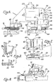
- the illustrated apparatus comprises, on a suitable support frame, generally indicated by 10 and which may be of any suitable structure, a pair of guide rails or parallel spaced slides 12 (only one of which has been shown in the drawings), these slides delimiting an internal housing shaped as a "U” 14 (FIGS. 2 and 3) in which the ends of metal strips 16 shaped like a "V" are retained, these being stacked -that is to say inserted or boxed into each other-with the vertices of the "V” slightly spaced due to the curvature deriving from said conformation in "V", as is essentially illustrated in FIG. 3.
- a suitable support frame generally indicated by 10 and which may be of any suitable structure
- a pair of guide rails or parallel spaced slides 12 delimiting an internal housing shaped as a "U” 14 (FIGS. 2 and 3) in which the ends of metal strips 16 shaped like a "V" are retained, these being stacked -that is to say inserted or boxed into each other-with the vertices
- listels can have, and generally have, an asymmetrical configuration according to which one branch of the V is longer than the other, and, because of their conformation, which delimits an angle as shown on the drawings or even smaller, these list They are very tightly packed together, so that to separate a listel 16 'from the stack of listels 16, some force must be exerted between said listel 16' and the last of the listels 16 remaining in the stack.
- the slides 12 delimit housings 14 shaped as a "U" and placed opposite one another, in which housings the stack of strips is free to slide down under the effect of the dead weight, by means of an appropriate inclination of said slides 12, which, according to the example illustrated, have a substantially sub-vertical arrangement, but in any case form an angle different from 0 relative to the vertical, which makes it possible to guarantee the support of the listels, at any time, on one of the sides of the housing 14 and thus to have a fixed reference point for the games of the listel separation system, a system which operates with great precision, as will be seen below.
- the slides 12 are mounted so as to be able to move horizontally on supports 18, by means of bearings 18 ′ and, jointly with the means which control the separation of the individual strips, these slides can be adjusted, for example by means of a conventional device using a nut 20, to adapt to strips of different lengths, which gives the machine, in an advantageous manner, very great application flexibility.
- the stack of strips 16 is inserted into the slides 12, the latter being suitably adjusted according to the length of the strips and the stack descends by gravity along said slides until it comes to stop against the supports, or end stops. stroke 22, which are advantageously arranged near the ends of the stacked strips, so as to ensure an exact positioning, in the vertical direction, of said strips and, in particular that of these strips which is placed last.
- the detachment operation of the latter list is carried out, according to the invention, by coordinated movements of said end-of-travel stops 22 and of a pair of conical points 24, which penetrate into the hollow or spaces which delimit between them the last and penultimate of the listels in the stack. Thanks to their conicity, said points thus exert a force tending to separate the last listel, over a distance which is sufficient to completely detach it from the listel placed above, while supporting the rest of the stack.
- the end of travel stops 22 are mounted on a sliding plate 26, which is driven by an alternating rectilinear movement determined by one or more motor means 28, constituted, for example, by cylinder-piston aggregates acting under the effect of a command, the end-of-travel stops 22 being, moreover, capable of moving longitudinally, at the same time as the slides 12, to guarantee at all times the presence of these stops in the vicinity of the ends of the strips, as mentioned more high.
- the movable element 26 laterally compotes, in a manner also adjustable in the horizontal direction, parallel to the listel, a cam 30 whose profile 32 is spanned by a cam follower roller 34 which, for its part, is mounted on the end d 'A lever 36 pivoting about a vertical axis 38 forming part of a support block 40.
- This block is itself adjustable in a longitudinal direction to the strips 16 to allow adaptation to strips of different lengths.
- the end of the lever 36 which is opposite the roller 34 relative to the pivot 38 has a face 42 which acts on the rounded head of a rod 46 axially movable in a pad 48 supported by the block 40 and carrying the tip 24. What has just been explained is illustrated in particular in FIGS. 4, 5 and 6 where it can also be noted that the rod 46 is biased by a spring 50 in the direction which makes the point 24 move away from the strips 16 so constantly maintaining the roller 34 pressing on the profile 32 of the cam 30.
- Said profile 32 has a first ascending part 52 which causes a similar displacement of the points 24, in order to cause the latter to be inserted exactly in the hollow or spacing which delimit between them the last and penultimate listels of the stack, and this while supporting said stack except the last strip without, however, forcibly tightening the latter strip against the stops 22.
- the profile 32 of the cam 30 has a bearing 54 parallel to the movement of the plate 26, this bearing 54 determining the maintenance of the tips 24 in said partially inserted position, with support of the stack of listels with the exception of the last during a subsequent movement of backward movement of the stops 22 beyond the support position of the last strip 16 '.
- the last listel of the stack would be free to separate from it, but it is however held in place by the significant friction force determined by the current embellishment condition of the listels.
- the profile 32 of the cam 30 has another ascending part 56 which, the movement of the plate 26 continuing in the X direction, determines a subsequent displacement of the tips 24 between the last and penultimate listels. Thanks to an appropriate conical conformation of the points 24, this displacement forces the last strip 16 'to separate completely from the stack to fall down under the effect of the force of gravity.
- the reverse-opposite movement of the plate 26 causes an inverse sequence to the movements just described. During this reverse sequence, there is partial recoil of the points 24, which however also ensure the support of the stack of strips 16, while the stops 22 advance until they are placed below said stack, after which the the points 24 are brought into the inactive position of FIG. 4 and the stack of listels 16 descends a little bit until they bear against the stops 22, which brings the hollow or spacing between the last and penultimate strips to line up with the axis of the tips 24, the system then being ready for a new detachment operation.
- the housing 58 is delimited by walls 64, 66 inclined up and down and back, that is to say towards the plate 26, so as to force the strip 16 'to take a determined position, which is in practice a support position by its longest side, both during the insertion of the strip into the housing 58 and during the subsequent displacement of said housing 58-in concert with the bars 60, 62-displacement having place during the movement of the plate 26 back in its rest condition, illustrated in FIG. 4.
- This displacement determines a translation of the housing 58 in the direction Y orthogonal to the major axis of the listel, until the latter is brought into abutment on a feed conveyor means, such as for example the conveyor belt 68 (FIG.
- this belt moves continuously parallel to the long axis of the strip 16 ', to drive the latter out of the guide housing 58, by passing it below a jumper connecting member 70 (FIG. 7) which allows the bars 60, 62 to be made integral with one another, on the expulsion or unloading side of the strip 16 '.
- the conveyor belt 68 brings said strip to a downstream work station, for example a pressing machine which comprises, suitably positioned above the belt 68 and below a pressing member, a stop element by which the listel is retained for the time which is necessary for the operator to insert therein the forms to be assembled and to close the listel on these forms.
- a pressing machine which comprises, suitably positioned above the belt 68 and below a pressing member, a stop element by which the listel is retained for the time which is necessary for the operator to insert therein the forms to be assembled and to close the listel on these forms.
Description
La présente invention concerne un appareil conçu pour prélever d'abord-à partir d'un paquet ou d'une pile-et pour alimenter ensuite en aval, des listels métalliques individuels conformés en "V", destinés tout spécialement à la retenue ou l'assemblage d'imprimés ou analogues, ces inprimés ou analogues étant insérés dans l'ouverture du V, après quoi le listel est écrasé à l'aide d'une machine spéciale, du type d'une presse.The present invention relates to an apparatus designed to take first - from a bundle or a pile - and then feed downstream, individual metal strips in the shape of a "V", intended especially for the retention or the 'assembly of printed matter or the like, these printed matter or the like being inserted into the opening of the V, after which the strip is crushed using a special machine, of the press type.
Dans les machines de pressage pour le conditionnement ou assemblage d'imprimés selon le système mentionné ci-dessus, dans lesquelles une commande provoque la descente d'un organne presseur sur le listel après qu'un opérateur a effectué le placement manuel de ce listel en appui contre des arrêts d'extrémité appropriés, puis l'insertion, également à la main, de l'imprimé ou des imprimés ou analogues dans l'ouverture en V du listel, l'opération qui consiste à arranger le listel au-dessous de l'organe presseur est désavantageuse du point de vue de la productivité, du fait de la perte considérable de temps occasionnée par la procédure de prélèvement des listels individuels d'un emballage usuel de cet article et d'orientation des listels, lorsque ceux-ci sont emballés en vrac. De plus, cette opération, qui demande de transporter les listels individuels, séparés, jusqu'au point de pressage, peut dans certain cas entraîner des risques pour l'opérateur, à moins que des mesures adéquates ne soient prises pour que la descente de l'organe presseur soit interdite tant que l'opérateur a ses doigts placés en dessous.In pressing machines for packaging or assembling printed matter according to the system mentioned above, in which a command causes a pressing organ to descend on the listel after an operator has carried out the manual placing of this listel in press against appropriate end stops, then insert, also by hand, the printed or printed matter or the like into the V-shaped opening of the listel, the operation which consists in arranging the listel below the pressing member is disadvantageous from the point of view of productivity, due to the considerable loss of time caused by the procedure for removing the individual strips from the usual packaging of this article and for orienting the strips, when these are packed in bulk. In addition, this operation, which requires transporting the individual, separate strips to the pressing point, can in certain cases entail risks for the operator, unless adequate measures are taken to ensure that the descent of the The pressing member is prohibited as long as the operator has his fingers underneath.
Pour les raisons ci-dessous, il se pose le problème, très ressenti dans ce secteur de l'industrie, d'automatiser l'opération de prélèvement des listels individuels d'une pile ou paquet de ses articles et celle ultérieure de l'acheminement--des listels vers le point de pressage.For the reasons below, there is the problem, which is very much felt in this sector of industry, of automating the operation of removing individual listels from a stack or package of its articles and that subsequent to the routing. - from the listels to the pressing point.
Les difficultés les plus grandes rencontrées pour la solution de ce problème résident essentiellement en ce que les listels étant empaquetés très étroitement serrés entre eux, le décollement du dernier listel demande und certain effort en même temps que la nécessité d'une retenue de l'avant-dernier listel.The greatest difficulties encountered in the solution of this problem mainly reside in the fact that the strips are very tightly packed together, the detachment of the last list requires a certain effort at the same time as the need for retaining the front - last listel.
En outre, il faut que les listels soient présentés au poste d'aval, en l'occurence la machine de pressage, selon une disposition et orientation bien précise, en vue d'éviter la nécessité de corriger ou ajuster à la main leur position.In addition, the strips must be presented at the downstream station, in this case the pressing machine, according to a very precise arrangement and orientation, in order to avoid the need to correct or adjust their position by hand.
On a déjà proposé un appareil que effectue le prélèvement et l'alimentation des listels en utilisant un champ magnétique pour séparer les listels d'avec un paquet ou pile de ces articles. Cependant, le fonctionnement d'un tel appareil n'est satisfaisant que si l'effort nécessaire pour décoller les listels l'un de l'autre est assez faible, c'est-à-dire, lorsque les listels sont largement ouverts et qu'ils affectent une configuration en L. Par conséquent, cet appareil de la technique connue n'est absolument pas en état d'opérer avec les listels en "V" qui rentrent dans le domaine d'application de la présente invention.A device has already been proposed which performs the picking and feeding of the listels using a magnetic field to separate the listels from a package or stack of these articles. However, the operation of such a device is only satisfactory if the effort required to lift the strips from one another is low enough, that is to say, when the strips are wide open and that 'They affect an L-shaped configuration. Consequently, this apparatus of the known technique is absolutely not in a condition to operate with "V" shaped strips which come within the scope of the present invention.
Ainsi, le but de la présente invention est de proposer un appareil capable d'affectuer d'une manière automatique et fiable lesdites-opérations de séparation des listels en "V" d'avec des paquets ou piles de ces listels et, ensuite, le transfert un à un des listels opportunément disposés et orientés, à des postes de traitement d'aval, en particulier, à une mchine de pressage.Thus, the object of the present invention is to propose an apparatus capable of carrying out in an automatic and reliable manner said operations of separation of the "V" shaped listels from the packets or stacks of these listels and, then, the one by one transfer of the appropriately arranged and oriented listels, to downstream processing stations, in particular, to a pressing machine.
L'invention a également pour but de proposer un appareil du type et aux caractéristiques précités, dans lequel lesdites opérations sont réalisées à l'aide de moyens opérateurs mécaniques particulièrement simples et économiques et tels q'ils permettent une adaptation rapide de l'appareil à des listels de formats différents.The invention also aims to provide an apparatus of the above type and characteristics, in which said operations are carried out using particularly simple and economical mechanical operator means and such that they allow rapid adaptation of the apparatus to listels of different formats.
D'une manière essentielle, cet appareil selon l'invention comprend: un magasin pour recevoir un paquet ou pile de listels dans laquelle les listels sont emboîtés l'un dans l'autre et disposés avec le sommet du V dirigé vers le bas; une ou plusieures butées de fin de course pour soutenir la pile par le dernier listel d'en bas; une paire de pointes coniques se situant longitudinalement par rapport à l'extrémité des listels et dont l'axe coincide longitudinalement avec le creux ou espacement délimité entre les sommets des demier et avant-dernier listels; des moyens pour commander des déplacements coordonnés, d'une part de rétraction our recul en position inactive des butées de fin de course, d'autre part d'avancement des pointes entre les listels dernier et avant-dernier jusqu'à obtenir la séparation du dernier listel de la pile tout en assurant le soutènement du reste de la pile; des moyens pour commander des déplacements coordonnés de retour en position active et de retour en position inactive des butées et des pointes respectivement; et des moyens pour prélever le listel ainsi séparé et pour l'acheminer vers des traitements ultérieurs.Essentially, this device according to the invention comprises: a magazine for receiving a packet or stack of listels in which the listels are nested one inside the other and arranged with the top of the V facing down; one or more end-of-travel stops to support the stack by the last strip from below; a pair of conical points situated longitudinally with respect to the end of the listels and whose axis coincides longitudinally with the hollow or spacing defined between the tops of the last and penultimate listels; means for controlling coordinated movements, on the one hand retraction or retraction in the inactive position of the end-of-travel stops, on the other hand for advancing the points between the last and penultimate strips until the separation of the last listel of the stack while ensuring the support of the rest of the stack; means for controlling coordinated movements of return to the active position and return to the inactive position of the stops and the spikes respectively; and means for taking the strip thus separated and for routing it to further processing.
Les différentes particularités et caractéristiques de l'invention seront comprises à la lecture de la description suivant d'un de ses modes préféres de mise en oeuvre, illustré à titre d'exemple sur les dessins annexés, dans lesquels:
- - La figure 1 est une vue de face, avec arrachements, dudit mode de mise en oeuvre de l'invention.
- - La figure 2 en est une vue partielle de côté.
- - La figure 3 est une vue en coupe selon un plan perpendiculaire au grand axe des listels, illustrant une rangée de listels empilés à l'intérieur d'un rail de guidage ou glissière de l'appareil 'selon l'invention, un des listels étant représenté lorsque séparé d'avec la pile.
- - La figure 4 représente, en vue de face par- teillement en coupe, et en vue d'en haut, un détail des moyens opérateurs qui effectuent la séparation du dernier listel, lesdits moyens étant dans leur position de repos.
- - La figure 5 représente, selon des vues correspondantes à celles de figure 4, le détail desdits moyens lors d'une phase intermédiaire de l'opération de décollement d'un listel.
- - La figure 6 represente, selon des vues correspondantes à celles des figures 4 et 5, le détail desdits moyens lors d'une phase finale de la séparation d'un listel.
- - La figure 7 représente, en vue partielle de côté et en vue partielle d'en haut, les moyens pour recevoir le listel détaché et pour faire ensuite déplacer le listel sur un dispositif ali- mentateur qui le délivre à une phase opératoire d'aval.
- - La figure 8 est une vue partielle de côté illustrant l'appareil dans la position de transfert du listel séparé sur les moyens d'alimentation en aval.
- -La figure 9 est une illustration schématique d'un dispositif accessoire pour rendre plus précise et sûre l'operation de séparation des listels.
- - Figure 1 is a front view, with parts broken away, of said embodiment of the invention.
- - Figure 2 is a partial side view.
- - Figure 3 is a sectional view along a plane perpendicular to the major axis of the strips, illustrating a row of strips stacked inside a guide rail or slide of the apparatus' according to the invention, one of the strips being shown when separated from the stack.
- FIG. 4 represents, in a front view likewise in section, and in top view, a detail of the operating means which carry out the separation of the last listel, said means being in their rest position.
- - Figure 5 shows, according to views corresponding to those of Figure 4, the detail of said means during an intermediate phase of the stripping operation of a listel.
- - Figure 6 shows, according to views corresponding to those of Figures 4 and 5, the detail of said means during a final phase of the separation of a listel.
- - Figure 7 shows, in partial side view and in partial view from above, the means for receiving the detached listel and then moving the listel on a feeding device which delivers it to a downstream operating phase .
- - Figure 8 is a partial side view illustrating the device in the transfer position of the separate listel on the downstream supply means.
- FIG. 9 is a schematic illustration of an accessory device to make the operation of separating the strips more precise and safe.
En se rapportant aux dessins, et d'abord aux figures 1 et 2, l'appareil illustré comprend, sur un bâti de support approprié, indiqué généralement par 10 et pouvant être d'une structure convenable quelconque, une pair de rails de guidage ou glissières espacées parallèles 12 (dont une seulement a été représentée sur les dessins), ces glissières délimitant un logement intérieur conformé en "U" 14 (figures 2 et 3) dans lequel sont retenues les extrémités de listels métalliques 16 conformés en "V", ceux-ci étant empilés-c'est-à-dire insérés ou enboÎtés l'un dans l'autre-avec les sommets des "V" légèrement espacés en raison de la courbure dérivant de ladite conformation en "V", comme cela est essentiellement illustré à la figure 3. Ces listels peuvent présenter, et présentent en général, une configuration asymétrique selon laquelle une branche du V est plus longue que l'autre, et, à cause de leur conformation, qui délimite un angle tel que figuré sur les dessins ou même plus petit, ces listels sont très étroitement serrés l'un à l'autre, de sorte que pour séparer un listel 16' d'avec la pile de listels 16, il faut qu'une certaine force s'exerce entre ledit listel 16' et le dernier des listels 16 restant dans la pile.Referring to the drawings, and firstly to Figures 1 and 2, the illustrated apparatus comprises, on a suitable support frame, generally indicated by 10 and which may be of any suitable structure, a pair of guide rails or parallel spaced slides 12 (only one of which has been shown in the drawings), these slides delimiting an internal housing shaped as a "U" 14 (FIGS. 2 and 3) in which the ends of
Comme dejà dit, les glissières 12 délimitent des logements 14 conformés en "U" et placés en face l'un de l'autre, dans lesquels logements la pile de listels est libre de glisser vers le bas sous l'effet du poids propre, gràce à une inclinaison appropriées desdites glissières 12, lesquelles, selon l'exemple illustré, ont une disposition sensiblement sub-verticale, mais forment en tout cas un angle différent de 0 par rapport à la verticale, ce qui permet de garantir l'appui des listels, à tout moment, sur un des côtés du logement 14 et d'avoir ainsi un point de repère fixe pour les jeux du système de séparation des listels, système qui opère avec une grande précision, comme on le verra par la suite. Les glissières 12 sont montées de façon a pouvoir se déplacer dans le sens horizontal sur des supports 18, par l'entremise de coussinets 18' et, cojointement avec les moyens qui commandent la séparation des listels individuels, ces glissières peuvent être ajustées, par exemple au moyen d'un dispositif conventionnel utilisant un écrou 20, pour s'adapter à des listels de longueurs différentes, ce qui confère à la machine, d'une manière avantageuse, une très grande flexibilité d'application.As already said, the
Ainsi, on insère la pile de listels 16 dans les glissières 12 celles-ci étant convenablement adjustées suivant la longueur des listels et la pile descend par gravité le long desdites glissières jusqu'à venir s'arrêter contre des appuis, ou butées de fin de course 22, lesquels sont avantageusement disposés à proximité des extrémités des listels empilés, de façon à assurer un positionnement exact, dans la direction verticale, desdits listels et, en particulier de celui de ces listels qui est placé en dernier.Thus, the stack of
L'opération de décollement de ce dernier listel est réalisée, selon l'invention, par des mouvements coordonnés desdites butées de fin de course 22 et d'une paire de pointes coniques 24, lesquelles pénètrent dans le creux ou espacements que délimitent entre eux le dernier et l'avant-dernier des listels de la pile. Grâce à leur conicitè, lesdites pointes, exercent, ainsi, une force tendant à séparer le dernier listel, sur une distance qui est suffisante pour détacher complètement celui-ci du listel placé au-dessus, tout en soutenant le reste de la pile. Pour cela, il est important que les mouvements alternatifs de rétraction et d'insertion des fin de course 22 et des pointes coniques 24, respectivement, soient coordonnés pour que, d'une part, le soutènement de la pile de listels soit assuré a tout moment et que, d'autre part, le listel dont la séparation est en cours soit empêché d'être serré à force entre les pointes 24 et les butées 22, ce que,pourrait causer sa déformation. Selon l'invention, cela est obtenu moyennant un asservissement des mouvements des pointes 24 aux mouvements des fin de course 22.The detachment operation of the latter list is carried out, according to the invention, by coordinated movements of said end-of-
A cette fin les butées de fin de course 22 sont montées sur une plaque coulissante 26, qui est animée d'un mouvement rectiligne alternatif déterminé par un ou plus moyens moteurs 28, constitués, par exemple, par des agrégats cylindre-piston agissant sous l'effet d'une commande, les butées de fin de course 22 étant, en outre, susceptibles de se déplacer longitudinalement, en même temps que les glissières 12, pour garantir à tout moment la presence de ces butées au voisinage des extrémités des listels, comme mentionné plus haut. L'element mobile 26 compote latéralement, d'une manière également ajustable dans la direction horizontale, parallèle au listel, une came 30 dont le profil 32 est parcorur par un galet suiveur de came 34 qui, lui, est monté sur l'extrémité d'un levier 36 pivotant autour d'une axe vertical 38 faisant partie d'un bloc de support 40. Ce bloc est lui-même ajustable dans une direction longitudinale aux listels 16 pour permettre l'adaptation à des listels de longueurs différentes. L'extrémité du levier 36 qui est opposée au rouleau 34 par rapport au pivot 38, a une face 42 qui agit sur la tête arrondie d'une tige 46 mobile axialement dans un coussinet 48 soutenu par le bloc 40 et portant la pointe 24. Ce qu'on vient d'exposer est illustré en particulier aux figures 4, 5 et 6 où l'on peut également noter que la tige 46 est sollicitée par un ressort 50 dans la direction qui fait éloigner la pointe 24 des listels 16 de façon à constamment maintenir le galet 34 en appui sur le profil 32 de la came 30.To this end, the end of
La séquence des opération qui amènent au décollement du dernier listel 16' de la pile respective est représentée aux figures 4, 5, 6, dont la première illustre les éléments constituant le dispositif en position de repos, c'est-à-dire avant que les moyens moteurs 28 aient reçu l'ordre pour l'opération de séparation d'un listel et d'acheminement de celui-ci. Pour cette position, les pointes sont retirées et la pile de listels 16 est soutenue par les butées de fin de course 22.The sequence of operations which lead to detachment of the last strip 16 'of the respective stack is shown in Figures 4, 5, 6, the first of which illustrates the elements constituting the device in the rest position, that is to say before the drive means 28 have received the order for the operation of separating a listel and of routing it. For this position, the tips are removed and the stack of
L'ordre étant parvenu aux moyens moteurs 28, ces derniers provoquent un mouvement vers l'arrière de la plaque 26 dans le sens indiqué par X sur la figure, ce qui a pour résultat un recul parteil des appuis 22 et un déplacement du profil 32 de la came 30 par rapport un galet 34 (fig. 5). Ledit profil 32 présente une première partie ascendente 52 qui provoque un déplacement parteil des pointes 24, pour amèner celles-ci à s'insérer exactement dans le creux ou espacement que délimitent entre eux les dernier at avant-dernier listels de la pile, et ce tout en soutenant ladite pile sauf le dernier listel sans toutefois serrer ce dernier listel de force contre les butées 22.The order having reached the motor means 28, the latter cause a rearward movement of the
A la suite de la partie ascendente 52, le profil 32 de la came 30 présente un palier 54 parallèle au mouvement de la plaque 26, ce palier 54 déterminant le maintien des pointes 24 dans ladite position partiellement insérée, avec soutènement de la pile de listels à l'exception du dernier au cours d'un mouvement ultérieur de recul des butées 22 au-delà de la position de support du dernier listel 16'. Dans cette condition, le dernier listel de la pile se trouverait être libre de se separer de celle-ci mais il est cependant maintenu en place par la force de frottement importante que détermine la condition d'emboltement actuel des listels.Following the
Pour réaliser ladite séparation du dernier listel-désormais libéré-le profil 32 de la came 30 présente une autre partie ascendente 56 laquelle, le mouvement de la plaque 26 se poursuivant dans le sens X, détermine un déplacement ultérieur des pointes 24 entre les dernier et avant dernier listels. Grâce à une conformation conique appropriée des pointes 24, ce déplacement oblige le dernier listel 16' de se séparer complètement de la pile pour tomber vers le bas sous l'effet de la force de gravité. Le mouvement de retour-sens opposé-de la plaque 26, provoque une séquence inverse des mouvements qu'on vient de décrire. Au cours de cette séquence inverse, il y a recul partiel des pointes 24, lesquelles assurent cependant également le soutènement de la pile de listels 16, tandis que les butées 22 avancent jusqu'à venir se placer au dessous de ladite pile, après quoi les les pointes 24 sont amenées dans la position inactive de figure 4 et la pile de listels 16 descend d'un petit peu jusqu'à se mettre en appui contre les butées 22, ce qui amène le creux ou espacement entre les dernier et avant-dernier listels à se mettre en ligne avec l'axe des pointes 24, le système étant alors prêt pour une nouvelle opération de décollement.To achieve said separation of the last listel - now released - the
Pour assurer ledit alignement dans une direction substantiellement horizontale (l'alignement en direction verticale étant assuré par les butées 22), on peut prévoir des dispositifs accessoires, en particulier en forme de doigts 72 (figure 9) qui sont placés en proximité des extremite listels 16, et qui peuvent être actionnés par des moyens d'actionnement (non illustrés) qui à son tour coopérant avec les moyens d'actionnement des pointes 24, comme précédemment décrits. Ces doigts 72 effectuent un mouvement oscillatoire à partir d'une position de répos 72a jusqu'à une position de travail 72 avant le prémier deplace- ment d'insertion des pointes 24. Ce mouvement des doigts jusqu'à la position 72 déplace les listels en pile et en particulier le dernier listel à partir de sa position de répos 16' a jusqu'à la position 16', comme définie par le côté posterieur des glissières 12, de façon à exactement positionner le creux entre les dernier et avant-dernier listels en alignement axial avec les pointes 24.To ensure said alignment in a substantially horizontal direction (alignment in the vertical direction being provided by the stops 22), it is possible to provide accessory devices, in particular in the form of fingers 72 (FIG. 9) which are placed near the list ends. 16, and which can be actuated by actuation means (not shown) which in turn cooperates with the actuation means of the
Ainsi détaché, le listel 16' descend jusqu'à un logement 58 de réception de ce listel, ce logement étant délimité par une pair de barres 60, 62 disposées parallèlement au listel et dont les mouvements sont eux-mêmes coordonnés aux mouvements de la plaque principale 26, de sorte que lorsque celle-ci est dans sa position complètement reculée (figure 6), le logement 58 vient se mettre exactement au dessous du, et en ligne avec ledit listel 16', ce logement 58 se trouvant situé, en outre, à un niveau en dessous du niveau des butéés d'extrémité 22. Comme particulièrement vu à la figure 7, le logement 58 est délimité par des parois 64, 66 inclinées de haut en bas et en arrière, c'est-à-dire vers la plaque 26, de manière à obliger le listel 16' à prendre une position déterminée, qui est en pratique une position d'appui par son côté le plus long, et ce tant au cours de l'insertion du listel dans le logement 58 que lors du déplacement subséquent dudit logement 58-de concert avec les barres 60, 62-déplacement ayant lieu au cours du mouvement de la plaque 26 de retour dans sa condition de repos, illustrée à la figure 4. Ce déplacement détermine une translation due logement 58 dans le sens Y orthogonal au grand axe du listel, juqu'à ce que celui-ci est amené en appui sur un moyen convoyeur d'alimentation, tel par exemple qui la bande transporteuse 68 (figure 8), cette bande déplacement en continu parallèlement au grand axe du listel 16', pour entraîner ce dernier hors du logement de guidage 58, en le faisant passer au-dessous d'un organe de liaison en cavalier 70 (figure 7) qui permet de rendre solidaires les barres 60, 62 l'une de l'autre, sur le côté expulsion ou déchargement du listel 16'.Thus detached, the strip 16 'descends to a
La bande transporteuse 68, amène ledit listel à un poste de travail d'aval, par exemple une machine de pressage qui comporte, positionné convénablement au-dessus de la bande 68 et an dessous d'un organe presseur, un élément d'arrêt par lequel le listel est retenu pendant le temps qui est nécessaire pour que l'opérateur insère dans celui-ci les imprimés à assembler et ferme le listel sur ces imprimés.The
Lorsqu'un accouplement de ce genre est prévu entre l'appareil selon l'invention et une machine à fermer les listels du type susmentionné, il convient d'arranger pour que l'ordre aux moyens moteurs 28 pour la mise en route d'une cycle de séparation d'un listel, soit donné par la machine à fermer les listels en particulier au cours du mouvement de l'organe presseur, de cette machine.When a coupling of this kind is provided between the device according to the invention and a machine for closing the strips of the aforementioned type, it is necessary to arrange so that the order to the motor means 28 for the starting of a separation cycle of a listel, or given by the machine to close the listels in particular during the movement of the pressing member, of this machine.
Claims (16)
Applications Claiming Priority (2)
| Application Number | Priority Date | Filing Date | Title |
|---|---|---|---|
| IT28745/78A IT1099904B (en) | 1978-10-13 | 1978-10-13 | EQUIPMENT FOR THE COLLECTION AND FEEDING OF V-SHAPED METAL STRIPS |
| IT2874578 | 1978-10-13 |
Publications (3)
| Publication Number | Publication Date |
|---|---|
| EP0010528A2 EP0010528A2 (en) | 1980-04-30 |
| EP0010528A3 EP0010528A3 (en) | 1980-05-14 |
| EP0010528B1 true EP0010528B1 (en) | 1982-06-23 |
Family
ID=11224108
Family Applications (1)
| Application Number | Title | Priority Date | Filing Date |
|---|---|---|---|
| EP79830035A Expired EP0010528B1 (en) | 1978-10-13 | 1979-10-02 | Device for separating and feeding v-shaped metallic strips |
Country Status (4)
| Country | Link |
|---|---|
| US (1) | US4298302A (en) |
| EP (1) | EP0010528B1 (en) |
| DE (1) | DE2963177D1 (en) |
| IT (1) | IT1099904B (en) |
Families Citing this family (1)
| Publication number | Priority date | Publication date | Assignee | Title |
|---|---|---|---|---|
| FR2619053B1 (en) * | 1987-08-06 | 1990-01-05 | Guilhon Jean Claude | AUTOMATIC FEEDING DEVICE FOR A STUFFED BAGUETTE BINDING MACHINE |
Family Cites Families (9)
| Publication number | Priority date | Publication date | Assignee | Title |
|---|---|---|---|---|
| US2974828A (en) * | 1958-04-16 | 1961-03-14 | Diamond National Corp | Vertical chute dispenser |
| GB1056050A (en) * | 1964-05-06 | 1967-01-25 | George Pulman & Sons Ltd | Improvements in and relating to binding leaves |
| US3513758A (en) * | 1965-08-13 | 1970-05-26 | Leonora Mining & Milling Co | Apparatus for taking,developing,compiling,and binding a series of photographs |
| US3468455A (en) * | 1967-11-14 | 1969-09-23 | Continental Can Co | Carton dispenser machine |
| US3477592A (en) * | 1968-03-27 | 1969-11-11 | Packaging Corp America | Denester |
| US3520046A (en) * | 1968-03-29 | 1970-07-14 | United Carr Inc | Automatic machine for attaching fasteners to a workpiece |
| US3542243A (en) * | 1968-10-02 | 1970-11-24 | Illinois Tool Works | Tray denesting device |
| US3701440A (en) * | 1969-06-20 | 1972-10-31 | Continental Can Co | Egg carton denester machine |
| GB1443821A (en) * | 1973-02-13 | 1976-07-28 | Ka Duk Lam | Sheet material fastening |
-
1978
- 1978-10-13 IT IT28745/78A patent/IT1099904B/en active
-
1979
- 1979-10-01 US US06/081,085 patent/US4298302A/en not_active Expired - Lifetime
- 1979-10-02 DE DE7979830035T patent/DE2963177D1/en not_active Expired
- 1979-10-02 EP EP79830035A patent/EP0010528B1/en not_active Expired
Also Published As
| Publication number | Publication date |
|---|---|
| EP0010528A2 (en) | 1980-04-30 |
| DE2963177D1 (en) | 1982-08-12 |
| EP0010528A3 (en) | 1980-05-14 |
| IT7828745A0 (en) | 1978-10-13 |
| IT1099904B (en) | 1985-09-28 |
| US4298302A (en) | 1981-11-03 |
Similar Documents
| Publication | Publication Date | Title |
|---|---|---|
| EP0281484B1 (en) | Method for adjusting the dimension of a plunger and die set for stamping blanks; plunger and die set | |
| FR2499039A1 (en) | DEVICE FOR INSERTING SHEET PACKETS INTO A WORKING MACHINE | |
| FR2537957A1 (en) | DEVICE FOR TAKING AND DRIVING SHEETS FOR TAKING, TRANSPORTING AND DEPOSITING SHEET MATERIAL | |
| FR2907100A1 (en) | PACKAGING AND PACKAGING INSTALLATION. | |
| EP0248700B1 (en) | Packaging machine for "american" boxes | |
| EP0451592B1 (en) | Process and device for forming stacks from the top of a pile of sheets in a machine for the production of packages | |
| EP2086841B1 (en) | Machine for transferring blanks for cartonboard boxes | |
| EP1073603B1 (en) | Stacking and transferring device for printed sections in the form of cartridges | |
| CH633761A5 (en) | Device for stacking flat objects, especially cut boxes folding. | |
| EP1369213B1 (en) | Apparatus for separating attachment points connecting piled cardboard sheets | |
| FR2584686A1 (en) | MANIPULATOR OF PAPER SHEETS APPLIED TO AN APPARATUS FOR REMOVAL AND SUPPLY OF PAPER SHEETS. | |
| CH607979A5 (en) | Device for handling stackable articles | |
| EP0389393A1 (en) | Device for automatically applying labels to boxes and pallets | |
| CH620170A5 (en) | ||
| FR2508016A1 (en) | DEVICE FOR TAKING WORKPIECES FROM A STACK | |
| EP0451568A1 (en) | Apparatus to work plate or sheet elements, equipped with a front waste removing device, to produce packings | |
| EP0010528B1 (en) | Device for separating and feeding v-shaped metallic strips | |
| EP0252936B1 (en) | Device for separating packets of sheets, particularly paper, forming a pile | |
| FR2654068A1 (en) | APPARATUS FOR SUPPLYING INDIVIDUAL PLAN FLANS FOR MACHINES FOR PACKAGING PRODUCTS IN CASES OF THE TYPE WITH ARTICULATED LID. | |
| FR2812281A1 (en) | BATTERY SUPPORT LOADING AND/OR UNLOADING DEVICE AND CORRESPONDING LOADING AND/OR UNLOADING STATION | |
| EP3820265B1 (en) | Method and device for cutting a radial electronic component | |
| FR2646620A1 (en) | Device for loading and unloading boxes with flat objects such as postal envelopes | |
| FR2690637A1 (en) | Handling installation for transporting blanks from a cutting machine to a stacking device. | |
| FR2573401A1 (en) | Method of stacking superimposed horizontal layers of objects on a pallet and installation for implementing this method | |
| FR2688205A1 (en) | SYSTEM FOR HANDLING OBJECTS IN PARTICULAR FOR AN AUTOMATIC MAIL SORTING MACHINE. |
Legal Events
| Date | Code | Title | Description |
|---|---|---|---|
| PUAI | Public reference made under article 153(3) epc to a published international application that has entered the european phase |
Free format text: ORIGINAL CODE: 0009012 |
|
| PUAL | Search report despatched |
Free format text: ORIGINAL CODE: 0009013 |
|
| AK | Designated contracting states |
Designated state(s): BE CH DE FR GB NL |
|
| AK | Designated contracting states |
Designated state(s): BE CH DE FR GB NL |
|
| 17P | Request for examination filed |
Effective date: 19800929 |
|
| GRAA | (expected) grant |
Free format text: ORIGINAL CODE: 0009210 |
|
| AK | Designated contracting states |
Designated state(s): BE CH DE FR GB NL |
|
| REF | Corresponds to: |
Ref document number: 2963177 Country of ref document: DE Date of ref document: 19820812 |
|
| PGFP | Annual fee paid to national office [announced via postgrant information from national office to epo] |
Ref country code: CH Payment date: 19830826 Year of fee payment: 5 |
|
| PGFP | Annual fee paid to national office [announced via postgrant information from national office to epo] |
Ref country code: BE Payment date: 19830831 Year of fee payment: 5 |
|
| PGFP | Annual fee paid to national office [announced via postgrant information from national office to epo] |
Ref country code: FR Payment date: 19831003 Year of fee payment: 5 |
|
| PGFP | Annual fee paid to national office [announced via postgrant information from national office to epo] |
Ref country code: DE Payment date: 19831006 Year of fee payment: 5 |
|
| PGFP | Annual fee paid to national office [announced via postgrant information from national office to epo] |
Ref country code: NL Payment date: 19831031 Year of fee payment: 5 |
|
| PG25 | Lapsed in a contracting state [announced via postgrant information from national office to epo] |
Ref country code: CH Effective date: 19841031 Ref country code: BE Effective date: 19841031 |
|
| BERE | Be: lapsed |
Owner name: AMIA S.A.S. DI ALLIEVI ADOLFO & C. Effective date: 19841002 |
|
| PG25 | Lapsed in a contracting state [announced via postgrant information from national office to epo] |
Ref country code: NL Effective date: 19850501 |
|
| GBPC | Gb: european patent ceased through non-payment of renewal fee | ||
| NLV4 | Nl: lapsed or anulled due to non-payment of the annual fee | ||
| PG25 | Lapsed in a contracting state [announced via postgrant information from national office to epo] |
Ref country code: FR Free format text: LAPSE BECAUSE OF NON-PAYMENT OF DUE FEES Effective date: 19850628 |
|
| REG | Reference to a national code |
Ref country code: CH Ref legal event code: PL |
|
| PG25 | Lapsed in a contracting state [announced via postgrant information from national office to epo] |
Ref country code: DE Effective date: 19850702 |
|
| REG | Reference to a national code |
Ref country code: FR Ref legal event code: ST |
|
| PG25 | Lapsed in a contracting state [announced via postgrant information from national office to epo] |
Ref country code: GB Effective date: 19881118 |
|
| PLBE | No opposition filed within time limit |
Free format text: ORIGINAL CODE: 0009261 |
|
| STAA | Information on the status of an ep patent application or granted ep patent |
Free format text: STATUS: NO OPPOSITION FILED WITHIN TIME LIMIT |