EP0010200B1 - Pressure control and relief valve and use of the same to supply a hydrokinetic torque converter - Google Patents
Pressure control and relief valve and use of the same to supply a hydrokinetic torque converter Download PDFInfo
- Publication number
- EP0010200B1 EP0010200B1 EP79103621A EP79103621A EP0010200B1 EP 0010200 B1 EP0010200 B1 EP 0010200B1 EP 79103621 A EP79103621 A EP 79103621A EP 79103621 A EP79103621 A EP 79103621A EP 0010200 B1 EP0010200 B1 EP 0010200B1
- Authority
- EP
- European Patent Office
- Prior art keywords
- pressure
- relief valve
- pressure control
- supply
- outlet
- Prior art date
- Legal status (The legal status is an assumption and is not a legal conclusion. Google has not performed a legal analysis and makes no representation as to the accuracy of the status listed.)
- Expired
Links
- 230000001970 hydrokinetic effect Effects 0.000 title claims description 6
- 239000012530 fluid Substances 0.000 claims description 10
- 238000013016 damping Methods 0.000 claims description 3
- 230000000903 blocking effect Effects 0.000 claims 4
- 230000001105 regulatory effect Effects 0.000 description 6
- 208000019300 CLIPPERS Diseases 0.000 description 5
- 208000021930 chronic lymphocytic inflammation with pontine perivascular enhancement responsive to steroids Diseases 0.000 description 5
- 230000007423 decrease Effects 0.000 description 2
- 238000003754 machining Methods 0.000 description 2
- 230000033228 biological regulation Effects 0.000 description 1
- 230000006866 deterioration Effects 0.000 description 1
- 238000005553 drilling Methods 0.000 description 1
- 238000005461 lubrication Methods 0.000 description 1
- 238000004519 manufacturing process Methods 0.000 description 1
- 230000000873 masking effect Effects 0.000 description 1
- 238000005096 rolling process Methods 0.000 description 1
Images

Classifications
-
- G—PHYSICS
- G05—CONTROLLING; REGULATING
- G05D—SYSTEMS FOR CONTROLLING OR REGULATING NON-ELECTRIC VARIABLES
- G05D16/00—Control of fluid pressure
- G05D16/04—Control of fluid pressure without auxiliary power
- G05D16/10—Control of fluid pressure without auxiliary power the sensing element being a piston or plunger
-
- F—MECHANICAL ENGINEERING; LIGHTING; HEATING; WEAPONS; BLASTING
- F16—ENGINEERING ELEMENTS AND UNITS; GENERAL MEASURES FOR PRODUCING AND MAINTAINING EFFECTIVE FUNCTIONING OF MACHINES OR INSTALLATIONS; THERMAL INSULATION IN GENERAL
- F16H—GEARING
- F16H61/00—Control functions within control units of change-speed- or reversing-gearings for conveying rotary motion ; Control of exclusively fluid gearing, friction gearing, gearings with endless flexible members or other particular types of gearing
- F16H61/38—Control of exclusively fluid gearing
- F16H61/48—Control of exclusively fluid gearing hydrodynamic
- F16H61/64—Control of exclusively fluid gearing hydrodynamic controlled by changing the amount of liquid in the working circuit
-
- G—PHYSICS
- G05—CONTROLLING; REGULATING
- G05D—SYSTEMS FOR CONTROLLING OR REGULATING NON-ELECTRIC VARIABLES
- G05D16/00—Control of fluid pressure
- G05D16/20—Control of fluid pressure characterised by the use of electric means
- G05D16/2006—Control of fluid pressure characterised by the use of electric means with direct action of electric energy on controlling means
- G05D16/2013—Control of fluid pressure characterised by the use of electric means with direct action of electric energy on controlling means using throttling means as controlling means
- G05D16/2024—Control of fluid pressure characterised by the use of electric means with direct action of electric energy on controlling means using throttling means as controlling means the throttling means being a multiple-way valve
-
- Y—GENERAL TAGGING OF NEW TECHNOLOGICAL DEVELOPMENTS; GENERAL TAGGING OF CROSS-SECTIONAL TECHNOLOGIES SPANNING OVER SEVERAL SECTIONS OF THE IPC; TECHNICAL SUBJECTS COVERED BY FORMER USPC CROSS-REFERENCE ART COLLECTIONS [XRACs] AND DIGESTS
- Y10—TECHNICAL SUBJECTS COVERED BY FORMER USPC
- Y10T—TECHNICAL SUBJECTS COVERED BY FORMER US CLASSIFICATION
- Y10T137/00—Fluid handling
- Y10T137/2496—Self-proportioning or correlating systems
- Y10T137/2559—Self-controlled branched flow systems
- Y10T137/2574—Bypass or relief controlled by main line fluid condition
- Y10T137/2605—Pressure responsive
- Y10T137/2617—Bypass or relief valve biased open
-
- Y—GENERAL TAGGING OF NEW TECHNOLOGICAL DEVELOPMENTS; GENERAL TAGGING OF CROSS-SECTIONAL TECHNOLOGIES SPANNING OVER SEVERAL SECTIONS OF THE IPC; TECHNICAL SUBJECTS COVERED BY FORMER USPC CROSS-REFERENCE ART COLLECTIONS [XRACs] AND DIGESTS
- Y10—TECHNICAL SUBJECTS COVERED BY FORMER USPC
- Y10T—TECHNICAL SUBJECTS COVERED BY FORMER US CLASSIFICATION
- Y10T137/00—Fluid handling
- Y10T137/7722—Line condition change responsive valves
- Y10T137/7781—With separate connected fluid reactor surface
- Y10T137/7793—With opening bias [e.g., pressure regulator]
- Y10T137/7794—With relief valve
Definitions
- the present invention due to the collaboration of Mr. Paul Aubert, relates to a pressure regulator-clipper using a unique elastic means as a reaction member for the pressure regulator function and for the pressure clipper function.
- Each of these devices has its own elastic means as a reaction element.
- devices which limit the pressure to a determined value there is generally a ball pushed by an elastic means against a seat in the center of which a pipe arrives. When the pressure in said pipe exceeds the determined value above which there would be risks of deterioration of the hydraulic circuit, the ball repels the elastic means and lets the oil pass into a chamber, which oil then escapes through a another pipe starting from said chamber and which is most often connected to the reservoir of the hydraulic circuit (see the above-mentioned French patent application 7439 146).
- devices which regulate the pressure there is generally a central spindle which can be moved on one side under the action of the pressure of the hydraulic circuit and on the opposite side under the action of an elastic means. The spindle is thus continuously in equilibrium under these two opposite actions (see the aforementioned US Pat. No. 3,517,681).
- This central spindle has various shoulders which, in their translational movement, play the role of drawer by hiding or discovering lights.
- Said drawer thus throttles, more or less, the arrival of the oil under pressure and allows its passage to the outlet pipe.
- each device also calls for the use of two bodies each having their own elastic means. If the hydraulic circuit is integrated in a hydraulic block, each device requires a bore and a housing for its own elastic means.
- the object of the present invention is to produce, from these teachings, a single particularly simple manufacturing pressure regulator-clipping device making it possible in particular to reduce the bulk and to facilitate the machining of the parts forming such a device.
- the pressure regulator-clipper comprises a body having a single central bore in which slides a pin acting as a drawer.
- This pin has two shoulders which, in their translational movement, play the role of drawer by masking or uncovering more or less, a light in which the fluid from the supply arrives and a light through which said fluid escapes.
- the outlet fluid acts on one of the ends of the drawer via a damping nozzle.
- On the other end of the drawer there is an elastic means which balances the opposite action of the pressure of the outlet fluid.
- Said elastic means acts at its other end on a shutter member of a second supply line of the supply circuit, this member being mounted, like the elastic means in the single central bore of the aforementioned body.
- the chamber in which the single elastic means are housed and the shutter member is connected to the atmosphere or to a pipe returning to the tank.
- the single elastic means can be a single spring.
- the closure member may be a ball.
- the pressure regulator-limiter according to the invention can advantageously be applied for supplying a determined pressure to a hydrokinetic torque converter and to a lubrication circuit of an automatic gearbox for a vehicle.
- the pressure regulator-limiter includes a body 1 in which a central bore is produced.
- Five chambers marked 2, 3, 4, 5 and 6 open into said bore which thus has four bearing surfaces marked 7, 8, 9 and 10.
- a central channel 11 opens into said central bore.
- the chamber 3 is connected to the outlet channel 15 by a channel 32.
- the chamber 4 is connected to the said channel 11 by channels 12, 13 and 14. From the chamber 2 leaves a channel 15. From the chamber 5 leaves a channel 16.
- the chamber 6 is connected to the chamber 5 by a channel 17 and a damping nozzle 18. These different channels are obtained by drilling and are then formed by plugs 19, 20, 21, 22, 23, 33 and 34.
- Channels 11, 15 and 16 have threads for fixing the fluid inlet or outlet pipes.
- a frustoconical bearing 24 connects the central channel 11 to the chamber 2.
- a ball 25 In the central bore are successively mounted a ball 25, a spring 26 and a pin 27.
- Said ball 25 is applied to the frustoconical bearing 24 under the action of the spring 26 which rests, on the one hand, on the ball 25 and, on the other hand, on the spindle 27.
- the said ball 25 thus has the function of closing the communication between the channel 11 and the chamber 2
- Said spindle 27 has two shoulders 28 and 29 which slide in the bearing surfaces 8 and 10. Said shoulders 28 ev, 29 hide or uncover them more or less; lights of rooms 4 and 5 when pin 27 is moving.
- a plug 30 closes the central bore.
- the regulator-clipper fulfills the regulator function in the following manner: at rest, when the pressure is zero in the supply circuit, that is to say in the channel 11 and the channels 12, 13 and 14, the single spring 26, on the one hand, presses the ball 25 on its frustoconical seat 24 and, on the other hand, pushes the spindle 27 against the plug 30.
- the regulator-limiter fulfills the function of limiter in the following manner: at rest, when the pressure is zero in the supply circuit, that is to say in the channel 11, the ball 25 is pressed against its seat 24 by the spring 26. When the pressure builds up in the channel 11 and remains below a predetermined value, the ball 25 remains; pressed against its seat 24 and continues to close the channel 11. When the pressure in the channel 11 1 exceeds said predetermined value, the ball 25 lifts from its seat 24 causing the pressure in the channel 11 to drop, by putting said communication in communication channel 11 with your room 2 and channel 15 connected to the tank or the atmosphere.
- This predetermined pressure value is given by the equality:
- Spring force 26 pressure in the channel 11 x section of the contact circle of the ball 25 on its seat, 24.
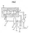
- FIG. 2 An example of use of the pressure regulator-limiter according to the invention is given in FIG. 2.
- a limiter-regulator 101 is connected to the power supply of a hydrokinetic torque converter 140.
- a pump 141 supplies the fluid flow rate through the line 142 which opens into the supply channel 111 of the clipping regulator 101.
- a line 143 is connected between the outlet channel 116 of the clipping regulator 101 and the converter 140.
- Said converter its fluid outlet connected to the pipe 144 which returns to the reservoir 145.
- a nozzle 146 placed on the return pipe 144, ensures the desired flow rate at the outlet of the converter 140.
- the regulator-limiter 101 thus provides protection for the converter which is supplied at a pressure regulated to a determined value and at a flow rate regulated in the same way. In addition, the regulator-limiter 101 provides protection of the entire hydraulic circuit against any accidental excess pressure.
Landscapes
- Physics & Mathematics (AREA)
- Fluid Mechanics (AREA)
- Engineering & Computer Science (AREA)
- General Physics & Mathematics (AREA)
- Automation & Control Theory (AREA)
- General Engineering & Computer Science (AREA)
- Mechanical Engineering (AREA)
- Fluid-Pressure Circuits (AREA)
- Safety Valves (AREA)
- Control Of Presses (AREA)
- Control Of Positive-Displacement Pumps (AREA)
Description
La présente invention, due à la collaboration de M. Paul Aubert, se rapporte à un régulateur-écrêteur de pression utilisant un moyen élastique unique comme organe de réaction pour la fonction régulateur de pression et pour la fonction écrêteur de pression.The present invention, due to the collaboration of Mr. Paul Aubert, relates to a pressure regulator-clipper using a unique elastic means as a reaction member for the pressure regulator function and for the pressure clipper function.
On connaît de nombreux dispositifs qui permettent de contrôler et de limiter la valeur de la pression d'un circuit hydraulique à une valeur déterminée. La demande de brevet français 74 39 146 publiée dans le N° 2.253.158 décrit un tel écrêteur de pression comportant un ensemble de soupapes réagissant à une surpression passagère pour ouvrir une communication avec un réservoir.Numerous devices are known which make it possible to control and limit the value of the pressure of a hydraulic circuit to a determined value. French patent application 74 39 146 published in No. 2,253,158 describes such a pressure limiter having a set of valves reacting to a temporary overpressure to open a communication with a tank.
On connaît également d'autres dispositifs qui permettent de contrôler la valeur de la pression d'un circuit hydraulique et de réguler ladite pression à une valeur voulue. Le brevet américain 3.517.681 décrit par exemple un dispositif régulateur de pression comprenant un tiroir mobile soumis à l'action d'un ressort à l'une de ses extrémités et à la contre-réaction de la pression de sortie régulée à son autre extrémité. La régulation de pression se fait par laminage du fluide hydraulique dans un passage dont les dimensions dépendent de la position du tiroir mobile.Other devices are also known which make it possible to control the value of the pressure of a hydraulic circuit and to regulate said pressure to a desired value. American patent 3,517,681 describes for example a pressure regulating device comprising a movable slide subjected to the action of a spring at one of its ends and to the feedback of the regulated outlet pressure at its other end . The pressure regulation is done by rolling the hydraulic fluid in a passage whose dimensions depend on the position of the movable slide.
Lorsqu'un circuit hydraulique nécessite l'emploi d'un régulateur et d'un écrêteur de pression, ces deux dispositifs différents sont séparés dans le circuit hydraulique où ils sont utilisés et sont reliés l'un à l'autre par des canalisations.When a hydraulic circuit requires the use of a pressure regulator and a pressure limiter, these two different devices are separated in the hydraulic circuit where they are used and are connected to each other by pipes.
Chacun de ces dispositifs comporte son propre moyen élastique comme élément de réaction. Dans les dispositifs qui limitent la pression à une valeur déterminée, il y a généralement une bille poussée par un moyen élastique contre un siège au centre duquel arrive une canalisation. Quand la pression dans ladite canalisation dépasse la valeur déterminée au-dessus de laquelle il y aurait des risques de détérioration du circuit hydraulique, la bille repousse le moyen élastique et laisse passer l'huile dans une chambre, laquelle huile s'échappe ensuite par une autre canalisation partant de ladite chambre et qui est reliée le plus souvent au réservoir du circuit hydraulique (voir la demande de brevet français 7439 146 précitée). Dans les dispositifs qui régulent la pression, il y a généralement une broche centrale qui peut être déplacée d'un côté sous l'action de la pression du circuit hydraulique et du côté opposé sous l'action d'un moyen élastique. La broche est ainsi continuellement en équilibre sous ces deux actions opposées (voir le brevet US 3.517.681 précité).Each of these devices has its own elastic means as a reaction element. In devices which limit the pressure to a determined value, there is generally a ball pushed by an elastic means against a seat in the center of which a pipe arrives. When the pressure in said pipe exceeds the determined value above which there would be risks of deterioration of the hydraulic circuit, the ball repels the elastic means and lets the oil pass into a chamber, which oil then escapes through a another pipe starting from said chamber and which is most often connected to the reservoir of the hydraulic circuit (see the above-mentioned French patent application 7439 146). In devices which regulate the pressure, there is generally a central spindle which can be moved on one side under the action of the pressure of the hydraulic circuit and on the opposite side under the action of an elastic means. The spindle is thus continuously in equilibrium under these two opposite actions (see the aforementioned US Pat. No. 3,517,681).
Cette broche centrale présente divers épaulements qui, dans leur déplacement en translation, jouent le rôle de tiroir en masquant ou découvrant des lumières.This central spindle has various shoulders which, in their translational movement, play the role of drawer by hiding or discovering lights.
Ledit tiroir étrangle ainsi, plus ou moins, l'arrivée de l'huile sous pression et permet son passage à la canalisation de sortie.Said drawer thus throttles, more or less, the arrival of the oil under pressure and allows its passage to the outlet pipe.
Ces deux types de dispositifs font aussi appel à l'utilisation de deux corps ayant chacun leur moyen élastique propre. Si le circuit hydraulique est intégré dans un bloc hydraulique, chaque dispositif exige un alésage et un logement pour son moyen élastique propre. La présente invention a pour objet de réaliser, à partir de ces enseignements, un seul dispositif régulateur-écrêteur de pression de fabrication particulièrement simple permettant notamment de réduire l'encombrement et de faciliter l'usinage des pièces formant un tel dispositif.These two types of device also call for the use of two bodies each having their own elastic means. If the hydraulic circuit is integrated in a hydraulic block, each device requires a bore and a housing for its own elastic means. The object of the present invention is to produce, from these teachings, a single particularly simple manufacturing pressure regulator-clipping device making it possible in particular to reduce the bulk and to facilitate the machining of the parts forming such a device.
Selon l'invention, le régulateur-écrêteur de pression comprend un corps présentant un alésage central unique dans lequel coulisse une broche faisant office de tiroir. Cette broche présente deux épaulement qui, dans leur déplacement en translation, jouent le rôle de tiroir en masquant ou découvrant plus ou moins, une lumière dans laquelle arrive le fluide de l'alimentation et une lumière par laquelle ledit fluide s'échappe. De plus, le fluide de sortie agit sur l'une des extrémités du tiroir par l'inter- mediaire d'un gicleur d'ammortissement. Sur l'autre extrémité du tiroir agit un moyen élastique qui équilibre l'action opposée de la pression du fluide de sortie. Ledit moyen élastique agit à son autre extrémité sur un organe d'obturation d'une deuxième canalisation d'arrivée du circuit d'alimentation, cet organe étant monté, comme le moyen élastique dans l'alésage central unique du corps précité. La chamber dans laquelle se logent le moyen élastique unique et l'organe d'obturation est reliée à l'atmosphère ou à une canalisation de retour au réservoir.According to the invention, the pressure regulator-clipper comprises a body having a single central bore in which slides a pin acting as a drawer. This pin has two shoulders which, in their translational movement, play the role of drawer by masking or uncovering more or less, a light in which the fluid from the supply arrives and a light through which said fluid escapes. In addition, the outlet fluid acts on one of the ends of the drawer via a damping nozzle. On the other end of the drawer there is an elastic means which balances the opposite action of the pressure of the outlet fluid. Said elastic means acts at its other end on a shutter member of a second supply line of the supply circuit, this member being mounted, like the elastic means in the single central bore of the aforementioned body. The chamber in which the single elastic means are housed and the shutter member is connected to the atmosphere or to a pipe returning to the tank.
Dans un mode de réalisation préféré, le moyen élastique unique peut être un ressort unique.In a preferred embodiment, the single elastic means can be a single spring.
Dans un autre mode de réalisation préféré, l'organe d'obturation peut être une bille.In another preferred embodiment, the closure member may be a ball.
Le régulateur-écrêteur de pression, selon l'invention, peut avantageusement être appliqué pour l'alimentation à une pression déterminée d'un convertisseur hydrocinétique de couple et d'un circuit de lubrification d'une boîte de vitesse automatique pour véhicule.The pressure regulator-limiter according to the invention can advantageously be applied for supplying a determined pressure to a hydrokinetic torque converter and to a lubrication circuit of an automatic gearbox for a vehicle.
Le régulateur-écrêteur de pression, selon l'invention, présente l'avantage de réunir en un seul appareil deux fonctions hydrauliques en utilisant un seul moyen élastique d'équilibrage. Il ne demande qu'un seul canal d'alimentation et un seul canal de retour au réservoir. Intégré dans un bloc hydraulique, le régulateur-écrêteur de pression, selon l'invention, ne demande qu'un seul alésage au lieu de deux et, lors de la réalisation du block ce dispositif n'exige qu'une seule tête d'usinage au lieu de deux. De plus, il n'y a qu'un seul moyen élastique et qu'un seul logement dudit moyen élastique. Par ailleurs, le régulateur-écrêteur de pression, selon l'invention, permet d'assurer la protection d'un convertisseur hydrocinétique de couple lorsqu'il est branché sur l'alimentation de celui-ci. D'autres caractéristiques et avantages de la présente invention ressortiront de la description qui suit d'un mode de réalisation particulier, donné à titre d'exemple et nullement limitatif, en référence aux dessins annexés sur lesquels:
- - la figure 1 représente, en coupe longitudinale, le régulateur-écrêteur selon l'invention;
- - la figure 2 représente le régulateur-écrêteur de la figure 1 qui alimente un convertisseur hydrocinétique de couple.
- - Figure 1 shows, in longitudinal section, the regulator-clipper according to the invention;
- - Figure 2 shows the clipping regulator of Figure 1 which supplies a hydrokinetic torque converter.
Tel que représenté en couple longitudinale sur la figure 1, le régulateur-écrêteur de pression comprend un corps 1 dans lequel est réalisé un alésage central. Cinq chambres repérées 2, 3, 4, 5 et 6 débouchent dans ledit alésage qui a ainsi quatre portées repérées 7, 8, 9 et 10.As shown in longitudinal couple in FIG. 1, the pressure regulator-limiter includes a
Un canal central 11 débouche dans ledit alésage central. La chambre 3 est reliée au canal 15 de sortie par un canal 32. La chambre 4 est reliée audit canal 11 par des canaux 12, 13 et 14. De la chambre 2 part un canal 15. De la chambre 5 part un canal 16. La chambre 6 est reliée à la chambre 5 par un canal 17 et un gicleur d'amortissement 18. Ces différents canaux sont obtenus par perçage et sont ensuite formés par des bouchons 19, 20, 21, 22, 23, 33 et 34.A
Les canaux 11, 15 et 16 ont des filetages pour la fixation des canalisations d'arrivée ou de départ d fluide. Une portée tronconique 24 relie le canal central 11 à la chambre 2. Dans l'alésage central viennent se monter successivement une bille 25, un ressort 26 et une broche 27. Ladite bille 25 vient s'appliquer sur la portée tronconique 24 sous l'action du ressort 26 qui s'appuie, d'une part, sur la bille 25 et, d'autre part, sur la broche 27. Ladite bille 25 a ainsi pour fonction d'obturer la communication entre le canal 11 et la chambre 2. Ladite broche 27 possède deuxepautements 28 et 29 qui coulissent dans les portées 8 et 10. Lesdits épaulements 28 ev,29 masquent ou découvrent plus ou mois les; lumières des chambres 4 et 5 lorsque la broche 27 se déplace. Un bouchon 30 vient fermer l'alésage central. Le régulateur-écrêteur, selon l'invention, remplit la fonction régulateur de la manière suivante: au repos, lorsque la pression est nulle dans le circuit d'alimentation, c'est-à-dire dans le canal 11 et les canaux 12, 13 et 14, le ressort unique 26, d'une part, plaque la bille 25 sur son siège tronconique 24 et, d'autre part, repousse la broche 27 contre le bouchon 30.
Quand le circuit hydraulique d'alimentation fonctionne, c'est-à-dire qu'une pression s'établit dans ledit circuit et qu'il y a un débit de fluide à travers les canaux 11, 12, 13 et 14, les chambres 4 et 5 et le canal de sortie 16, la broche centrale 27 est soumise à l'action de deux forces opposées: d'une part, la force due au ressort 26 et, d'autre part, la force due à l'action de la pression dans la chambre 6 sur l'extrémité de la broche 27, c'est-à-dire sur la section totale de l'épaulement 29.When the hydraulic supply circuit operates, that is to say that a pressure is established in said circuit and that there is a flow of fluid through the
Quand la force due à la pression régnant dans la chambre 6 devient supérieure à l'effort du ressort 26, la broche centrale 27 se déplace et vient étrangler le passage d'huile 31. De ce fait, la pression en aval dudit passage 31 diminue, donc l'action due à cette pression dans la chambre 6 sur la broche 27 diminue et sous l'action du ressort 26 ledit passage 31 augmente. La pression qui règne dans le canal de sortie 16, dans le canal 17 et la chambre 6 est donc fonction du ressort 26 et de la section de l'épaulement 29 de la broche 27. La pression régulée à la sortie du dispositif est donnée par l'égalité: Effort du ressort = pression régulée de sortie x section de l'épaulement 29 de la broche 27.When the force due to the pressure prevailing in the chamber 6 becomes greater than the force of the
Le régulateur-écrêteur, selon l'invention, remplit la fonction écrêteur de la manière suivante: au repos, lorsque la pression est nulle dans le circuit d'alimentation, c'est-à-dire dans le canal 11, la bille 25 est plaquée sur son siège 24 par le ressort 26. Lorsque la pression s'établit dans le canal 11 et reste inférieure à une valeur prédéterminée, la bille 25 reste; plaquée sur son siège 24 et continue d'obturer le canal 11. Lorsque la pression dans le canal 11 1 dépasse ladite valeur prédéterminée, la bille 25 se soulève de son siège 24 faisant chuter la pression dans le canai 11, en mettant en communication ledit canal 11 avec ta chambre 2 et le canal 15 relié au réservoir ou à l'atmosphere. Cette valeur de pression prédéterminée est donnée par l'égalité: Effort du ressort 26 = pression dans le canal 11 x section du cercle de contact de la bille 25 sur son siège, 24.The regulator-limiter, according to the invention, fulfills the function of limiter in the following manner: at rest, when the pressure is zero in the supply circuit, that is to say in the
Un exemple d'utilisation du régulateur-écrêteur de pression, selon l'invention, est donné dans la figure 2. Un régulateur-écrêteur 101, décrit ci-dessus, est branché sur l'alimentation d'un convertisseur hydrocinétique de couple 140. Une pompe 141 fournit le débit de fluide à travers la canalisation 142 qui débouche dans le canal d'alimentation 111 du régulateur-écrêteur 101. Une canalisation 143 est branchée entre le canal de sortie 116 du régulateur écrêteur 101 et le convertisseur 140. Ledit convertisseur sa sortie de fluide branchée sur la canalisation 144 qui retourne au réservoir 145. Un gicleur 146, placé sur la canalisation de retour 144, assure le débit désiré à la sortie du convertisseur 140.An example of use of the pressure regulator-limiter according to the invention is given in FIG. 2. A limiter-
Le régulateur-écrêteur 101 assure ainsi une protection du convertisseur qui se trouve alimenté à une pression régulée à une valeur déterminée et à un débit régulé de la même manière. De plus, le régulateur-écrêteur 101 assure une protection de tout le circuit hydraulique contre tout excès de pression accidentel.The regulator-
Claims (4)
Applications Claiming Priority (2)
| Application Number | Priority Date | Filing Date | Title |
|---|---|---|---|
| FR7827976 | 1978-09-29 | ||
| FR7827976A FR2437654A1 (en) | 1978-09-29 | 1978-09-29 | PRESSURE REGULATOR |
Publications (2)
| Publication Number | Publication Date |
|---|---|
| EP0010200A1 EP0010200A1 (en) | 1980-04-30 |
| EP0010200B1 true EP0010200B1 (en) | 1982-06-02 |
Family
ID=9213196
Family Applications (1)
| Application Number | Title | Priority Date | Filing Date |
|---|---|---|---|
| EP79103621A Expired EP0010200B1 (en) | 1978-09-29 | 1979-09-24 | Pressure control and relief valve and use of the same to supply a hydrokinetic torque converter |
Country Status (10)
| Country | Link |
|---|---|
| US (1) | US4302937A (en) |
| EP (1) | EP0010200B1 (en) |
| AR (1) | AR219192A1 (en) |
| BR (1) | BR7906265A (en) |
| CA (1) | CA1126617A (en) |
| DE (1) | DE2963018D1 (en) |
| ES (1) | ES483801A1 (en) |
| FR (1) | FR2437654A1 (en) |
| PT (1) | PT70113A (en) |
| RO (1) | RO79166A (en) |
Cited By (1)
| Publication number | Priority date | Publication date | Assignee | Title |
|---|---|---|---|---|
| CN104455394A (en) * | 2014-10-29 | 2015-03-25 | 中国北车集团大连机车研究所有限公司 | Hydraulic transmission box hydraulic drive gear shifting and hydraulic unit oil charge and discharge control mechanism |
Families Citing this family (11)
| Publication number | Priority date | Publication date | Assignee | Title |
|---|---|---|---|---|
| US4505293A (en) * | 1981-10-10 | 1985-03-19 | Bl Technology Limited | Fluid flow control valve |
| EP0103349A1 (en) * | 1982-08-12 | 1984-03-21 | General Motors Corporation | Variable pressure control valve |
| FR2570521B1 (en) * | 1984-09-18 | 1987-12-11 | Renault | REGULATION DEVICE WITH TWO PRESSURE DOMAINS |
| DE3532602C2 (en) * | 1984-09-25 | 1994-07-28 | Jidosha Kiki Co | Flow control valve |
| US4753264A (en) * | 1986-03-19 | 1988-06-28 | Jidosha Kiki Co., Ltd. | Flow control valve |
| DE3712716A1 (en) * | 1986-08-01 | 1988-02-04 | Man Nutzfahrzeuge Gmbh | PROCESS FOR REDUCING LOSSES, CHANGING THE SUPPLY CURRENT OF A CONSTANT FEED PUMP AND DEVICE FOR PERFORMING THE PROCESS |
| US4953582A (en) * | 1989-07-27 | 1990-09-04 | Detroit Diesel Corporation | Combined pressure regulator and relief valve having a single biasing means |
| DE19909690C2 (en) * | 1999-03-05 | 2002-02-21 | Voith Turbo Kg | Control method for filling a hydrodynamic component and control device |
| US8584691B2 (en) * | 2008-10-03 | 2013-11-19 | Hammonds Technical Services, Inc. | Additive dispensing system and method |
| CH700246B1 (en) * | 2009-10-30 | 2010-07-30 | Liebherr Machines Bulle Sa | Pressure controlling and/or pressure regulation device for e.g. hydraulic system, has valve block and/or cartridge comprising two inlet openings and outlet opening, where flow exists between one of inlet openings and outlet opening |
| JP6906053B2 (en) | 2016-11-30 | 2021-07-21 | サン−ゴバン パフォーマンス プラスティックス レンコール リミティド | Adjustable torque assembly |
Family Cites Families (16)
| Publication number | Priority date | Publication date | Assignee | Title |
|---|---|---|---|---|
| DE876010C (en) * | 1951-02-24 | 1953-05-07 | Mueller & Co Schwelmer Eisen | Intermittently working regulator |
| BE543023A (en) * | 1954-12-03 | 1900-01-01 | ||
| FR1118929A (en) * | 1955-01-07 | 1956-06-13 | Rech S Etudes | Pressure regulator for fluids under pressure |
| US2984251A (en) * | 1957-12-23 | 1961-05-16 | Lear Inc | Pressure regulator |
| FR1197119A (en) * | 1958-01-31 | 1959-11-27 | Hydraulic regulator | |
| FR1399357A (en) * | 1964-06-23 | 1965-05-14 | Int Harvester Co | Pressure relief valve for hydraulic circuits, in particular for agricultural tractors |
| US3324873A (en) * | 1964-07-27 | 1967-06-13 | Webcor Inc | Combined pressure regulator and relief valve |
| US3367354A (en) * | 1964-11-09 | 1968-02-06 | Gen Motors Corp | Valve |
| US3517681A (en) * | 1968-05-23 | 1970-06-30 | United Aircraft Corp | Viscosity independent pressure regulating valve |
| JPS4820657B1 (en) * | 1970-01-30 | 1973-06-22 | ||
| US3756264A (en) * | 1971-07-30 | 1973-09-04 | Iv Pressure Controllers Ltd | Pressure control devices for fluid flow systems |
| DE2323550C3 (en) * | 1973-05-10 | 1978-09-21 | Kloeckner-Humboldt-Deutz Ag, 5000 Koeln | Filling valve for a hydrodynamic unit |
| DE2359755C2 (en) * | 1973-11-30 | 1985-06-05 | Robert Bosch Gmbh, 7000 Stuttgart | Hydraulic switching valve |
| SU510590A1 (en) * | 1974-08-10 | 1976-04-15 | Всесоюзный научно-исследовательский и проектно-конструкторский институт промышленных гидроприводов и гидроавтоматики | Hydraulic drive |
| US4046160A (en) * | 1976-02-02 | 1977-09-06 | International Harvester Company | Transmission clutches with sequence valve and piston-controlled pressure modulator |
| DE2611216C2 (en) * | 1976-03-17 | 1981-12-03 | G.L. Rexroth Gmbh, 8770 Lohr | Device for cavitation-free pressure limitation of working fluid |
-
1978
- 1978-09-29 FR FR7827976A patent/FR2437654A1/en active Granted
-
1979
- 1979-08-24 PT PT70113A patent/PT70113A/en unknown
- 1979-08-31 ES ES483801A patent/ES483801A1/en not_active Expired
- 1979-09-24 DE DE7979103621T patent/DE2963018D1/en not_active Expired
- 1979-09-24 EP EP79103621A patent/EP0010200B1/en not_active Expired
- 1979-09-27 RO RO9878279A patent/RO79166A/en unknown
- 1979-09-28 US US06/079,737 patent/US4302937A/en not_active Expired - Lifetime
- 1979-09-28 CA CA336,674A patent/CA1126617A/en not_active Expired
- 1979-09-28 BR BR7906265A patent/BR7906265A/en unknown
- 1979-09-29 AR AR27825079A patent/AR219192A1/en active
Cited By (1)
| Publication number | Priority date | Publication date | Assignee | Title |
|---|---|---|---|---|
| CN104455394A (en) * | 2014-10-29 | 2015-03-25 | 中国北车集团大连机车研究所有限公司 | Hydraulic transmission box hydraulic drive gear shifting and hydraulic unit oil charge and discharge control mechanism |
Also Published As
| Publication number | Publication date |
|---|---|
| FR2437654A1 (en) | 1980-04-25 |
| BR7906265A (en) | 1980-06-03 |
| AR219192A1 (en) | 1980-07-31 |
| FR2437654B1 (en) | 1983-02-25 |
| CA1126617A (en) | 1982-06-29 |
| RO79166A (en) | 1982-06-25 |
| EP0010200A1 (en) | 1980-04-30 |
| DE2963018D1 (en) | 1982-07-22 |
| PT70113A (en) | 1979-09-01 |
| ES483801A1 (en) | 1980-05-16 |
| US4302937A (en) | 1981-12-01 |
Similar Documents
| Publication | Publication Date | Title |
|---|---|---|
| EP0010200B1 (en) | Pressure control and relief valve and use of the same to supply a hydrokinetic torque converter | |
| EP0656495B1 (en) | Liquid distributor with solenoid valves | |
| EP0330575B1 (en) | Hydraulic circuit comprising a safety valve for a hydraulic actuator | |
| US5085246A (en) | Plural-rate surge-suppressing valve | |
| EP0009749B1 (en) | Pressure control valve with 3 or 4 levels | |
| EP2006587B1 (en) | Watertight valve system | |
| FR2910566A1 (en) | VALVE ARRANGEMENT WITH HYDRAULIC CONTROL | |
| FR2480368A1 (en) | MULTI-SECTION CONTROL VALVE ASSEMBLY | |
| FR2834018A1 (en) | DEVICE FOR MONITORING A QUANTITY OF FLUID INTENDED FOR HEAVY CONSTRUCTION MACHINERY | |
| EP0187051B1 (en) | Double range pressure regulation device | |
| FR2916377A1 (en) | METHOD OF PROTECTING AGAINST FLOW SUPPLY OF A DEVICE WITH MUTE PERCUSSIONS BY AN INCOMPRESSIBLE FLUID UNDER PRESSURE AND APPARATUS FOR CARRYING OUT SAID METHOD | |
| FR2509829A1 (en) | SOLENOID CONTROLLED PRESSURE REGULATOR | |
| EP0176431B1 (en) | Two-level pressure regulation device | |
| FR2546983A1 (en) | Hydraulic valve system for priority motor | |
| FR2543504A1 (en) | PRESSURE LIMIT VALVE FOR COMPRESSED AIR BRAKING SYSTEMS ON MOTOR VEHICLES | |
| FR2597165A1 (en) | Bypass valve | |
| EP0082048A1 (en) | Hydraulic directional control valve | |
| FR2492941A1 (en) | DIFFERENTIAL PRESSURE LIMITING DEVICE WITH VALVES | |
| FR2628502A1 (en) | PRIORITY VALVE AND METHOD FOR MAKING A FLUID FLOW A PRIORITY | |
| FR2539463A1 (en) | CONTROL DEVICE FOR HELICOIDAL COMPRESSORS | |
| FR2595433A1 (en) | DECELERATION CONTROL DEVICE | |
| FR2473195A1 (en) | FLOW REGULATOR FOR HYDRAULIC CIRCUITS | |
| FR2732438A1 (en) | TWO-WAY VALVE OF THE DOUBLE-WAY PRESSURE DETECTION TYPE | |
| FR2549166A1 (en) | VALVE ARRANGEMENT FOR LIMITING PRESSURE IN A PRESSURIZED SYSTEM | |
| FR2488366A1 (en) | Two-channel fluid flow regulator - contains differential pressure piston acting on slide valve containing calibrated orifice to provide constant flow |
Legal Events
| Date | Code | Title | Description |
|---|---|---|---|
| PUAI | Public reference made under article 153(3) epc to a published international application that has entered the european phase |
Free format text: ORIGINAL CODE: 0009012 |
|
| AK | Designated contracting states |
Designated state(s): BE DE GB IT NL SE |
|
| 17P | Request for examination filed | ||
| ITF | It: translation for a ep patent filed | ||
| GRAA | (expected) grant |
Free format text: ORIGINAL CODE: 0009210 |
|
| AK | Designated contracting states |
Designated state(s): BE DE GB IT NL SE |
|
| REF | Corresponds to: |
Ref document number: 2963018 Country of ref document: DE Date of ref document: 19820722 |
|
| PGFP | Annual fee paid to national office [announced via postgrant information from national office to epo] |
Ref country code: BE Payment date: 19840630 Year of fee payment: 6 |
|
| PGFP | Annual fee paid to national office [announced via postgrant information from national office to epo] |
Ref country code: SE Payment date: 19840930 Year of fee payment: 6 |
|
| PGFP | Annual fee paid to national office [announced via postgrant information from national office to epo] |
Ref country code: NL Payment date: 19870930 Year of fee payment: 9 |
|
| PG25 | Lapsed in a contracting state [announced via postgrant information from national office to epo] |
Ref country code: SE Effective date: 19890925 |
|
| PG25 | Lapsed in a contracting state [announced via postgrant information from national office to epo] |
Ref country code: BE Effective date: 19890930 |
|
| BERE | Be: lapsed |
Owner name: REGIE NATIONALE DES USINES RENAULT Effective date: 19890930 |
|
| PG25 | Lapsed in a contracting state [announced via postgrant information from national office to epo] |
Ref country code: NL Effective date: 19900401 |
|
| NLV4 | Nl: lapsed or anulled due to non-payment of the annual fee | ||
| PGFP | Annual fee paid to national office [announced via postgrant information from national office to epo] |
Ref country code: GB Payment date: 19910808 Year of fee payment: 13 |
|
| PGFP | Annual fee paid to national office [announced via postgrant information from national office to epo] |
Ref country code: DE Payment date: 19910816 Year of fee payment: 13 |
|
| ITTA | It: last paid annual fee | ||
| PG25 | Lapsed in a contracting state [announced via postgrant information from national office to epo] |
Ref country code: GB Effective date: 19920924 |
|
| GBPC | Gb: european patent ceased through non-payment of renewal fee |
Effective date: 19920924 |
|
| PG25 | Lapsed in a contracting state [announced via postgrant information from national office to epo] |
Ref country code: DE Effective date: 19930602 |
|
| EUG | Se: european patent has lapsed |
Ref document number: 79103621.3 Effective date: 19900521 |
|
| PLBE | No opposition filed within time limit |
Free format text: ORIGINAL CODE: 0009261 |
|
| STAA | Information on the status of an ep patent application or granted ep patent |
Free format text: STATUS: NO OPPOSITION FILED WITHIN TIME LIMIT |