EP0010200B1 - Druckregel- und Druckbegrenzungsventil und Anwendung desselben zur Speisung eines Hydrokinetischenwandler - Google Patents
Druckregel- und Druckbegrenzungsventil und Anwendung desselben zur Speisung eines Hydrokinetischenwandler Download PDFInfo
- Publication number
- EP0010200B1 EP0010200B1 EP79103621A EP79103621A EP0010200B1 EP 0010200 B1 EP0010200 B1 EP 0010200B1 EP 79103621 A EP79103621 A EP 79103621A EP 79103621 A EP79103621 A EP 79103621A EP 0010200 B1 EP0010200 B1 EP 0010200B1
- Authority
- EP
- European Patent Office
- Prior art keywords
- pressure
- relief valve
- pressure control
- supply
- outlet
- Prior art date
- Legal status (The legal status is an assumption and is not a legal conclusion. Google has not performed a legal analysis and makes no representation as to the accuracy of the status listed.)
- Expired
Links
- 230000001970 hydrokinetic effect Effects 0.000 title claims description 6
- 239000012530 fluid Substances 0.000 claims description 10
- 238000013016 damping Methods 0.000 claims description 3
- 230000000903 blocking effect Effects 0.000 claims 4
- 230000001105 regulatory effect Effects 0.000 description 6
- 208000019300 CLIPPERS Diseases 0.000 description 5
- 208000021930 chronic lymphocytic inflammation with pontine perivascular enhancement responsive to steroids Diseases 0.000 description 5
- 230000007423 decrease Effects 0.000 description 2
- 238000003754 machining Methods 0.000 description 2
- 230000033228 biological regulation Effects 0.000 description 1
- 230000006866 deterioration Effects 0.000 description 1
- 238000005553 drilling Methods 0.000 description 1
- 238000005461 lubrication Methods 0.000 description 1
- 238000004519 manufacturing process Methods 0.000 description 1
- 230000000873 masking effect Effects 0.000 description 1
- 238000005096 rolling process Methods 0.000 description 1
Images

Classifications
-
- G—PHYSICS
- G05—CONTROLLING; REGULATING
- G05D—SYSTEMS FOR CONTROLLING OR REGULATING NON-ELECTRIC VARIABLES
- G05D16/00—Control of fluid pressure
- G05D16/04—Control of fluid pressure without auxiliary power
- G05D16/10—Control of fluid pressure without auxiliary power the sensing element being a piston or plunger
-
- F—MECHANICAL ENGINEERING; LIGHTING; HEATING; WEAPONS; BLASTING
- F16—ENGINEERING ELEMENTS AND UNITS; GENERAL MEASURES FOR PRODUCING AND MAINTAINING EFFECTIVE FUNCTIONING OF MACHINES OR INSTALLATIONS; THERMAL INSULATION IN GENERAL
- F16H—GEARING
- F16H61/00—Control functions within control units of change-speed- or reversing-gearings for conveying rotary motion ; Control of exclusively fluid gearing, friction gearing, gearings with endless flexible members or other particular types of gearing
- F16H61/38—Control of exclusively fluid gearing
- F16H61/48—Control of exclusively fluid gearing hydrodynamic
- F16H61/64—Control of exclusively fluid gearing hydrodynamic controlled by changing the amount of liquid in the working circuit
-
- G—PHYSICS
- G05—CONTROLLING; REGULATING
- G05D—SYSTEMS FOR CONTROLLING OR REGULATING NON-ELECTRIC VARIABLES
- G05D16/00—Control of fluid pressure
- G05D16/20—Control of fluid pressure characterised by the use of electric means
- G05D16/2006—Control of fluid pressure characterised by the use of electric means with direct action of electric energy on controlling means
- G05D16/2013—Control of fluid pressure characterised by the use of electric means with direct action of electric energy on controlling means using throttling means as controlling means
- G05D16/2024—Control of fluid pressure characterised by the use of electric means with direct action of electric energy on controlling means using throttling means as controlling means the throttling means being a multiple-way valve
-
- Y—GENERAL TAGGING OF NEW TECHNOLOGICAL DEVELOPMENTS; GENERAL TAGGING OF CROSS-SECTIONAL TECHNOLOGIES SPANNING OVER SEVERAL SECTIONS OF THE IPC; TECHNICAL SUBJECTS COVERED BY FORMER USPC CROSS-REFERENCE ART COLLECTIONS [XRACs] AND DIGESTS
- Y10—TECHNICAL SUBJECTS COVERED BY FORMER USPC
- Y10T—TECHNICAL SUBJECTS COVERED BY FORMER US CLASSIFICATION
- Y10T137/00—Fluid handling
- Y10T137/2496—Self-proportioning or correlating systems
- Y10T137/2559—Self-controlled branched flow systems
- Y10T137/2574—Bypass or relief controlled by main line fluid condition
- Y10T137/2605—Pressure responsive
- Y10T137/2617—Bypass or relief valve biased open
-
- Y—GENERAL TAGGING OF NEW TECHNOLOGICAL DEVELOPMENTS; GENERAL TAGGING OF CROSS-SECTIONAL TECHNOLOGIES SPANNING OVER SEVERAL SECTIONS OF THE IPC; TECHNICAL SUBJECTS COVERED BY FORMER USPC CROSS-REFERENCE ART COLLECTIONS [XRACs] AND DIGESTS
- Y10—TECHNICAL SUBJECTS COVERED BY FORMER USPC
- Y10T—TECHNICAL SUBJECTS COVERED BY FORMER US CLASSIFICATION
- Y10T137/00—Fluid handling
- Y10T137/7722—Line condition change responsive valves
- Y10T137/7781—With separate connected fluid reactor surface
- Y10T137/7793—With opening bias [e.g., pressure regulator]
- Y10T137/7794—With relief valve
Definitions
- the present invention due to the collaboration of Mr. Paul Aubert, relates to a pressure regulator-clipper using a unique elastic means as a reaction member for the pressure regulator function and for the pressure clipper function.
- Each of these devices has its own elastic means as a reaction element.
- devices which limit the pressure to a determined value there is generally a ball pushed by an elastic means against a seat in the center of which a pipe arrives. When the pressure in said pipe exceeds the determined value above which there would be risks of deterioration of the hydraulic circuit, the ball repels the elastic means and lets the oil pass into a chamber, which oil then escapes through a another pipe starting from said chamber and which is most often connected to the reservoir of the hydraulic circuit (see the above-mentioned French patent application 7439 146).
- devices which regulate the pressure there is generally a central spindle which can be moved on one side under the action of the pressure of the hydraulic circuit and on the opposite side under the action of an elastic means. The spindle is thus continuously in equilibrium under these two opposite actions (see the aforementioned US Pat. No. 3,517,681).
- This central spindle has various shoulders which, in their translational movement, play the role of drawer by hiding or discovering lights.
- Said drawer thus throttles, more or less, the arrival of the oil under pressure and allows its passage to the outlet pipe.
- each device also calls for the use of two bodies each having their own elastic means. If the hydraulic circuit is integrated in a hydraulic block, each device requires a bore and a housing for its own elastic means.
- the object of the present invention is to produce, from these teachings, a single particularly simple manufacturing pressure regulator-clipping device making it possible in particular to reduce the bulk and to facilitate the machining of the parts forming such a device.
- the pressure regulator-clipper comprises a body having a single central bore in which slides a pin acting as a drawer.
- This pin has two shoulders which, in their translational movement, play the role of drawer by masking or uncovering more or less, a light in which the fluid from the supply arrives and a light through which said fluid escapes.
- the outlet fluid acts on one of the ends of the drawer via a damping nozzle.
- On the other end of the drawer there is an elastic means which balances the opposite action of the pressure of the outlet fluid.
- Said elastic means acts at its other end on a shutter member of a second supply line of the supply circuit, this member being mounted, like the elastic means in the single central bore of the aforementioned body.
- the chamber in which the single elastic means are housed and the shutter member is connected to the atmosphere or to a pipe returning to the tank.
- the single elastic means can be a single spring.
- the closure member may be a ball.
- the pressure regulator-limiter according to the invention can advantageously be applied for supplying a determined pressure to a hydrokinetic torque converter and to a lubrication circuit of an automatic gearbox for a vehicle.
- the pressure regulator-limiter includes a body 1 in which a central bore is produced.
- Five chambers marked 2, 3, 4, 5 and 6 open into said bore which thus has four bearing surfaces marked 7, 8, 9 and 10.
- a central channel 11 opens into said central bore.
- the chamber 3 is connected to the outlet channel 15 by a channel 32.
- the chamber 4 is connected to the said channel 11 by channels 12, 13 and 14. From the chamber 2 leaves a channel 15. From the chamber 5 leaves a channel 16.
- the chamber 6 is connected to the chamber 5 by a channel 17 and a damping nozzle 18. These different channels are obtained by drilling and are then formed by plugs 19, 20, 21, 22, 23, 33 and 34.
- Channels 11, 15 and 16 have threads for fixing the fluid inlet or outlet pipes.
- a frustoconical bearing 24 connects the central channel 11 to the chamber 2.
- a ball 25 In the central bore are successively mounted a ball 25, a spring 26 and a pin 27.
- Said ball 25 is applied to the frustoconical bearing 24 under the action of the spring 26 which rests, on the one hand, on the ball 25 and, on the other hand, on the spindle 27.
- the said ball 25 thus has the function of closing the communication between the channel 11 and the chamber 2
- Said spindle 27 has two shoulders 28 and 29 which slide in the bearing surfaces 8 and 10. Said shoulders 28 ev, 29 hide or uncover them more or less; lights of rooms 4 and 5 when pin 27 is moving.
- a plug 30 closes the central bore.
- the regulator-clipper fulfills the regulator function in the following manner: at rest, when the pressure is zero in the supply circuit, that is to say in the channel 11 and the channels 12, 13 and 14, the single spring 26, on the one hand, presses the ball 25 on its frustoconical seat 24 and, on the other hand, pushes the spindle 27 against the plug 30.
- the regulator-limiter fulfills the function of limiter in the following manner: at rest, when the pressure is zero in the supply circuit, that is to say in the channel 11, the ball 25 is pressed against its seat 24 by the spring 26. When the pressure builds up in the channel 11 and remains below a predetermined value, the ball 25 remains; pressed against its seat 24 and continues to close the channel 11. When the pressure in the channel 11 1 exceeds said predetermined value, the ball 25 lifts from its seat 24 causing the pressure in the channel 11 to drop, by putting said communication in communication channel 11 with your room 2 and channel 15 connected to the tank or the atmosphere.
- This predetermined pressure value is given by the equality:
- Spring force 26 pressure in the channel 11 x section of the contact circle of the ball 25 on its seat, 24.
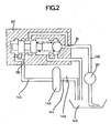
- FIG. 2 An example of use of the pressure regulator-limiter according to the invention is given in FIG. 2.
- a limiter-regulator 101 is connected to the power supply of a hydrokinetic torque converter 140.
- a pump 141 supplies the fluid flow rate through the line 142 which opens into the supply channel 111 of the clipping regulator 101.
- a line 143 is connected between the outlet channel 116 of the clipping regulator 101 and the converter 140.
- Said converter its fluid outlet connected to the pipe 144 which returns to the reservoir 145.
- a nozzle 146 placed on the return pipe 144, ensures the desired flow rate at the outlet of the converter 140.
- the regulator-limiter 101 thus provides protection for the converter which is supplied at a pressure regulated to a determined value and at a flow rate regulated in the same way. In addition, the regulator-limiter 101 provides protection of the entire hydraulic circuit against any accidental excess pressure.
Landscapes
- Physics & Mathematics (AREA)
- Fluid Mechanics (AREA)
- Engineering & Computer Science (AREA)
- General Physics & Mathematics (AREA)
- Automation & Control Theory (AREA)
- General Engineering & Computer Science (AREA)
- Mechanical Engineering (AREA)
- Safety Valves (AREA)
- Fluid-Pressure Circuits (AREA)
- Control Of Positive-Displacement Pumps (AREA)
- Control Of Presses (AREA)
Claims (4)
Applications Claiming Priority (2)
| Application Number | Priority Date | Filing Date | Title |
|---|---|---|---|
| FR7827976A FR2437654A1 (fr) | 1978-09-29 | 1978-09-29 | Regulateur-ecreteur de pression |
| FR7827976 | 1978-09-29 |
Publications (2)
| Publication Number | Publication Date |
|---|---|
| EP0010200A1 EP0010200A1 (de) | 1980-04-30 |
| EP0010200B1 true EP0010200B1 (de) | 1982-06-02 |
Family
ID=9213196
Family Applications (1)
| Application Number | Title | Priority Date | Filing Date |
|---|---|---|---|
| EP79103621A Expired EP0010200B1 (de) | 1978-09-29 | 1979-09-24 | Druckregel- und Druckbegrenzungsventil und Anwendung desselben zur Speisung eines Hydrokinetischenwandler |
Country Status (10)
| Country | Link |
|---|---|
| US (1) | US4302937A (de) |
| EP (1) | EP0010200B1 (de) |
| AR (1) | AR219192A1 (de) |
| BR (1) | BR7906265A (de) |
| CA (1) | CA1126617A (de) |
| DE (1) | DE2963018D1 (de) |
| ES (1) | ES483801A1 (de) |
| FR (1) | FR2437654A1 (de) |
| PT (1) | PT70113A (de) |
| RO (1) | RO79166A (de) |
Cited By (1)
| Publication number | Priority date | Publication date | Assignee | Title |
|---|---|---|---|---|
| CN104455394A (zh) * | 2014-10-29 | 2015-03-25 | 中国北车集团大连机车研究所有限公司 | 液力传动箱液动换挡、液力单元充排油控制机构 |
Families Citing this family (11)
| Publication number | Priority date | Publication date | Assignee | Title |
|---|---|---|---|---|
| US4505293A (en) * | 1981-10-10 | 1985-03-19 | Bl Technology Limited | Fluid flow control valve |
| EP0103349A1 (de) * | 1982-08-12 | 1984-03-21 | General Motors Corporation | Variables Druckregelventil |
| FR2570521B1 (fr) * | 1984-09-18 | 1987-12-11 | Renault | Dispositif de regulation a deux domaines de pression |
| DE3532602C2 (de) * | 1984-09-25 | 1994-07-28 | Jidosha Kiki Co | Strömungssteuerventil |
| US4753264A (en) * | 1986-03-19 | 1988-06-28 | Jidosha Kiki Co., Ltd. | Flow control valve |
| DE3712716A1 (de) * | 1986-08-01 | 1988-02-04 | Man Nutzfahrzeuge Gmbh | Verfahren zum verlustarmen veraendern des foerderstromes einer konstantspeisepumpe und vorrichtung zur durchfuehrung des verfahrens |
| US4953582A (en) * | 1989-07-27 | 1990-09-04 | Detroit Diesel Corporation | Combined pressure regulator and relief valve having a single biasing means |
| DE19909690C2 (de) * | 1999-03-05 | 2002-02-21 | Voith Turbo Kg | Verfahren zur Steuerung zur Befüllung eines hydrodynamischen Bauelementes und Steuervorrichtung |
| US8584691B2 (en) * | 2008-10-03 | 2013-11-19 | Hammonds Technical Services, Inc. | Additive dispensing system and method |
| CH700246B1 (de) * | 2009-10-30 | 2010-07-30 | Liebherr Machines Bulle Sa | Vorrichtung zur Druckbegrenzung bzw. Druckregelung. |
| EP3548225B1 (de) | 2016-11-30 | 2022-03-09 | Saint-Gobain Performance Plastics Rencol Limited | Einstellbare drehmomentanordnung |
Family Cites Families (16)
| Publication number | Priority date | Publication date | Assignee | Title |
|---|---|---|---|---|
| DE876010C (de) * | 1951-02-24 | 1953-05-07 | Mueller & Co Schwelmer Eisen | Intermittierend arbeitender Regler |
| BE543023A (de) * | 1954-12-03 | 1900-01-01 | ||
| FR1118929A (fr) * | 1955-01-07 | 1956-06-13 | Rech S Etudes | Détendeur pour fluides sous pression |
| US2984251A (en) * | 1957-12-23 | 1961-05-16 | Lear Inc | Pressure regulator |
| FR1197119A (fr) * | 1958-01-31 | 1959-11-27 | Régulateur hydraulique | |
| FR1399357A (fr) * | 1964-06-23 | 1965-05-14 | Int Harvester Co | Soupape de décompression pour circuits hydrauliques, en particulier pour des tracteurs agricoles |
| US3324873A (en) * | 1964-07-27 | 1967-06-13 | Webcor Inc | Combined pressure regulator and relief valve |
| US3367354A (en) * | 1964-11-09 | 1968-02-06 | Gen Motors Corp | Valve |
| US3517681A (en) * | 1968-05-23 | 1970-06-30 | United Aircraft Corp | Viscosity independent pressure regulating valve |
| JPS4820657B1 (de) * | 1970-01-30 | 1973-06-22 | ||
| US3756264A (en) * | 1971-07-30 | 1973-09-04 | Iv Pressure Controllers Ltd | Pressure control devices for fluid flow systems |
| DE2323550C3 (de) * | 1973-05-10 | 1978-09-21 | Kloeckner-Humboldt-Deutz Ag, 5000 Koeln | Füllventil für eine hydrodynamische Einheit |
| DE2359755C2 (de) | 1973-11-30 | 1985-06-05 | Robert Bosch Gmbh, 7000 Stuttgart | Hydraulisches Schaltventil |
| SU510590A1 (ru) * | 1974-08-10 | 1976-04-15 | Всесоюзный научно-исследовательский и проектно-конструкторский институт промышленных гидроприводов и гидроавтоматики | Гидропривод |
| US4046160A (en) * | 1976-02-02 | 1977-09-06 | International Harvester Company | Transmission clutches with sequence valve and piston-controlled pressure modulator |
| DE2611216C2 (de) * | 1976-03-17 | 1981-12-03 | G.L. Rexroth Gmbh, 8770 Lohr | Vorrichtung zur kavitationsfreien Druckbegrenzung von Arbeitsflüssigkeit |
-
1978
- 1978-09-29 FR FR7827976A patent/FR2437654A1/fr active Granted
-
1979
- 1979-08-24 PT PT70113A patent/PT70113A/pt unknown
- 1979-08-31 ES ES483801A patent/ES483801A1/es not_active Expired
- 1979-09-24 DE DE7979103621T patent/DE2963018D1/de not_active Expired
- 1979-09-24 EP EP79103621A patent/EP0010200B1/de not_active Expired
- 1979-09-27 RO RO9878279A patent/RO79166A/ro unknown
- 1979-09-28 BR BR7906265A patent/BR7906265A/pt unknown
- 1979-09-28 US US06/079,737 patent/US4302937A/en not_active Expired - Lifetime
- 1979-09-28 CA CA336,674A patent/CA1126617A/fr not_active Expired
- 1979-09-29 AR AR27825079A patent/AR219192A1/es active
Cited By (1)
| Publication number | Priority date | Publication date | Assignee | Title |
|---|---|---|---|---|
| CN104455394A (zh) * | 2014-10-29 | 2015-03-25 | 中国北车集团大连机车研究所有限公司 | 液力传动箱液动换挡、液力单元充排油控制机构 |
Also Published As
| Publication number | Publication date |
|---|---|
| BR7906265A (pt) | 1980-06-03 |
| FR2437654B1 (de) | 1983-02-25 |
| RO79166A (ro) | 1982-06-25 |
| AR219192A1 (es) | 1980-07-31 |
| CA1126617A (fr) | 1982-06-29 |
| EP0010200A1 (de) | 1980-04-30 |
| FR2437654A1 (fr) | 1980-04-25 |
| US4302937A (en) | 1981-12-01 |
| PT70113A (fr) | 1979-09-01 |
| ES483801A1 (es) | 1980-05-16 |
| DE2963018D1 (en) | 1982-07-22 |
Similar Documents
| Publication | Publication Date | Title |
|---|---|---|
| EP0010200B1 (de) | Druckregel- und Druckbegrenzungsventil und Anwendung desselben zur Speisung eines Hydrokinetischenwandler | |
| EP0656495B1 (de) | Flüssigkeitsverteiler mit Elektromagnetventilen | |
| EP0330575B1 (de) | Hydraulischer Kreislauf mit zugehörigem Sicherheitsventil für hydraulische Verbraucher | |
| US5085246A (en) | Plural-rate surge-suppressing valve | |
| EP0009749B1 (de) | Druckregelventil mit 3 oder 4 Druckwerten | |
| FR2910566A1 (fr) | Agencement de soupapes a commande hydraulique | |
| FR2480368A1 (fr) | Ensemble de valves de commande a sections multiples | |
| FR2834018A1 (fr) | Dispositif pour controler une quantite de fluide destine aux engins de chantier lourds | |
| EP2150380B1 (de) | Durch eine unter druck stehende unkomprimierbare flüssigkeit betätigte schlagvorrichtung | |
| EP0187051B1 (de) | Zweibereich-Druckreglervorrichtung | |
| FR2509829A1 (fr) | Regulateur de pression a commande par solenoide | |
| EP0176431B1 (de) | Zwei-Stufen-Druckregelungsvorrichtung | |
| FR2543504A1 (fr) | Soupape de limitation de pression pour des systemes de freinage a air comprime sur vehicules automobiles | |
| FR2597165A1 (fr) | Soupape de derivation | |
| EP0082048A1 (de) | Hydraulikwegeventil | |
| FR2492941A1 (fr) | Dispositif limiteur de pression differentielle a clapets | |
| FR2628502A1 (fr) | Vanne de priorite et procede pour rendre prioritaire un ecoulement de fluide | |
| FR2539463A1 (fr) | Dispositif de commande pour compresseurs helicoidaux | |
| FR2595433A1 (fr) | Dispositif de commande de deceleration | |
| FR2473195A1 (fr) | Regulateur de debit pour circuits hydrauliques | |
| FR2732438A1 (fr) | Soupape a deux voies du type a detection de pression a double sens | |
| FR2549166A1 (fr) | Agencement de valve pour limiter la pression dans un systeme sous pression | |
| US1216985A (en) | Reducing-valve. | |
| FR2488366A1 (fr) | Valve regulatrice de debit comportant un tiroir deplacable contre la force d'un ressort par une pression differentielle creee sur un orifice calibre | |
| EP0310466B1 (de) | Vorrichtung für Proportionalsteuerung mit Strömungsverstärkung |
Legal Events
| Date | Code | Title | Description |
|---|---|---|---|
| PUAI | Public reference made under article 153(3) epc to a published international application that has entered the european phase |
Free format text: ORIGINAL CODE: 0009012 |
|
| AK | Designated contracting states |
Designated state(s): BE DE GB IT NL SE |
|
| 17P | Request for examination filed | ||
| ITF | It: translation for a ep patent filed | ||
| GRAA | (expected) grant |
Free format text: ORIGINAL CODE: 0009210 |
|
| AK | Designated contracting states |
Designated state(s): BE DE GB IT NL SE |
|
| REF | Corresponds to: |
Ref document number: 2963018 Country of ref document: DE Date of ref document: 19820722 |
|
| PGFP | Annual fee paid to national office [announced via postgrant information from national office to epo] |
Ref country code: BE Payment date: 19840630 Year of fee payment: 6 |
|
| PGFP | Annual fee paid to national office [announced via postgrant information from national office to epo] |
Ref country code: SE Payment date: 19840930 Year of fee payment: 6 |
|
| PGFP | Annual fee paid to national office [announced via postgrant information from national office to epo] |
Ref country code: NL Payment date: 19870930 Year of fee payment: 9 |
|
| PG25 | Lapsed in a contracting state [announced via postgrant information from national office to epo] |
Ref country code: SE Effective date: 19890925 |
|
| PG25 | Lapsed in a contracting state [announced via postgrant information from national office to epo] |
Ref country code: BE Effective date: 19890930 |
|
| BERE | Be: lapsed |
Owner name: REGIE NATIONALE DES USINES RENAULT Effective date: 19890930 |
|
| PG25 | Lapsed in a contracting state [announced via postgrant information from national office to epo] |
Ref country code: NL Effective date: 19900401 |
|
| NLV4 | Nl: lapsed or anulled due to non-payment of the annual fee | ||
| PGFP | Annual fee paid to national office [announced via postgrant information from national office to epo] |
Ref country code: GB Payment date: 19910808 Year of fee payment: 13 |
|
| PGFP | Annual fee paid to national office [announced via postgrant information from national office to epo] |
Ref country code: DE Payment date: 19910816 Year of fee payment: 13 |
|
| ITTA | It: last paid annual fee | ||
| PG25 | Lapsed in a contracting state [announced via postgrant information from national office to epo] |
Ref country code: GB Effective date: 19920924 |
|
| GBPC | Gb: european patent ceased through non-payment of renewal fee |
Effective date: 19920924 |
|
| PG25 | Lapsed in a contracting state [announced via postgrant information from national office to epo] |
Ref country code: DE Effective date: 19930602 |
|
| EUG | Se: european patent has lapsed |
Ref document number: 79103621.3 Effective date: 19900521 |
|
| PLBE | No opposition filed within time limit |
Free format text: ORIGINAL CODE: 0009261 |
|
| STAA | Information on the status of an ep patent application or granted ep patent |
Free format text: STATUS: NO OPPOSITION FILED WITHIN TIME LIMIT |