EP0009622B1 - Verfahren zum Herstellen einer Hochspannungsdurchführung - Google Patents
Verfahren zum Herstellen einer Hochspannungsdurchführung Download PDFInfo
- Publication number
- EP0009622B1 EP0009622B1 EP79103199A EP79103199A EP0009622B1 EP 0009622 B1 EP0009622 B1 EP 0009622B1 EP 79103199 A EP79103199 A EP 79103199A EP 79103199 A EP79103199 A EP 79103199A EP 0009622 B1 EP0009622 B1 EP 0009622B1
- Authority
- EP
- European Patent Office
- Prior art keywords
- synthetic resin
- resin film
- insulating material
- process according
- wound
- Prior art date
- Legal status (The legal status is an assumption and is not a legal conclusion. Google has not performed a legal analysis and makes no representation as to the accuracy of the status listed.)
- Expired
Links
- 238000004519 manufacturing process Methods 0.000 title claims abstract description 16
- 239000011810 insulating material Substances 0.000 claims abstract description 59
- 238000000034 method Methods 0.000 claims abstract description 38
- 238000004804 winding Methods 0.000 claims abstract description 10
- 229920003002 synthetic resin Polymers 0.000 claims abstract 19
- 239000000057 synthetic resin Substances 0.000 claims abstract 19
- 239000002184 metal Substances 0.000 claims description 31
- 239000011888 foil Substances 0.000 claims description 28
- 239000000463 material Substances 0.000 claims description 4
- 239000004744 fabric Substances 0.000 claims 1
- 239000002985 plastic film Substances 0.000 description 58
- 229920006255 plastic film Polymers 0.000 description 58
- 239000007787 solid Substances 0.000 description 4
- 239000004020 conductor Substances 0.000 description 3
- 238000010276 construction Methods 0.000 description 2
- 230000007423 decrease Effects 0.000 description 2
- 230000003247 decreasing effect Effects 0.000 description 2
- 238000010438 heat treatment Methods 0.000 description 2
- 238000009413 insulation Methods 0.000 description 2
- 239000004033 plastic Substances 0.000 description 2
- 239000011347 resin Substances 0.000 description 2
- 229920005989 resin Polymers 0.000 description 2
- 230000037303 wrinkles Effects 0.000 description 2
- 230000002745 absorbent Effects 0.000 description 1
- 239000002250 absorbent Substances 0.000 description 1
- 239000000853 adhesive Substances 0.000 description 1
- 230000001070 adhesive effect Effects 0.000 description 1
- 238000005452 bending Methods 0.000 description 1
- 230000015572 biosynthetic process Effects 0.000 description 1
- 238000005266 casting Methods 0.000 description 1
- 230000000295 complement effect Effects 0.000 description 1
- 238000007596 consolidation process Methods 0.000 description 1
- 229910003460 diamond Inorganic materials 0.000 description 1
- 239000010432 diamond Substances 0.000 description 1
- 230000005684 electric field Effects 0.000 description 1
- 230000014759 maintenance of location Effects 0.000 description 1
- 239000000155 melt Substances 0.000 description 1
- 229920006300 shrink film Polymers 0.000 description 1
Images

Classifications
-
- H—ELECTRICITY
- H01—ELECTRIC ELEMENTS
- H01B—CABLES; CONDUCTORS; INSULATORS; SELECTION OF MATERIALS FOR THEIR CONDUCTIVE, INSULATING OR DIELECTRIC PROPERTIES
- H01B19/00—Apparatus or processes specially adapted for manufacturing insulators or insulating bodies
-
- B—PERFORMING OPERATIONS; TRANSPORTING
- B29—WORKING OF PLASTICS; WORKING OF SUBSTANCES IN A PLASTIC STATE IN GENERAL
- B29C—SHAPING OR JOINING OF PLASTICS; SHAPING OF MATERIAL IN A PLASTIC STATE, NOT OTHERWISE PROVIDED FOR; AFTER-TREATMENT OF THE SHAPED PRODUCTS, e.g. REPAIRING
- B29C53/00—Shaping by bending, folding, twisting, straightening or flattening; Apparatus therefor
- B29C53/56—Winding and joining, e.g. winding spirally
- B29C53/562—Winding and joining, e.g. winding spirally spirally
-
- B—PERFORMING OPERATIONS; TRANSPORTING
- B29—WORKING OF PLASTICS; WORKING OF SUBSTANCES IN A PLASTIC STATE IN GENERAL
- B29L—INDEXING SCHEME ASSOCIATED WITH SUBCLASS B29C, RELATING TO PARTICULAR ARTICLES
- B29L2031/00—Other particular articles
- B29L2031/34—Electrical apparatus, e.g. sparking plugs or parts thereof
- B29L2031/3412—Insulators
Definitions
- the invention is based on a method for producing a high-voltage bushing, in which a comparatively thin plastic film is wound on a mandrel together with an insulating material web, forming common turns in each case.
- a paper tape is used as the insulating material web, which preferably consists of crepe paper.
- the paper should be absorbent because it is wound together with a thinner plastic film that melts under the influence of heat and pressure and partially penetrates the adjacent paper web.
- the high-voltage bushing thus produced has the advantage that it can also be exposed to high operating temperatures.
- insulating material for example paper or film material
- several strips of insulating material are spirally wound next to one another, in such a way that the strips are wound simultaneously in two layers; one layer covers the joints of the other layer.
- the insulating sheets for the two layers have, among other things, a different thickness. A firm wrap can be formed, so that bending of the mandrel is largely avoided.
- the invention is based on the object of specifying a method for producing a high-voltage bushing with a common winding of an insulating material web and a thin plastic film, with which a largely wrinkle-free and thus also largely gap-free construction of the bushing can be achieved.
- the thin plastic film is guided onto the mandrel above the insulating material web and is wound under tension with elastic expansion.
- the thin plastic film due to the tension exerted on it, lies evenly against the insulating material web located underneath or running onto the mandrel, and this in turn without folds on the mandrel or the windings underneath from the insulating material web and presses on the thin plastic film.
- the stretching of the thin plastic film can be achieved using a comparatively low tensile stress because the plastic film is relatively thin.
- the thin plastic film thus serves as a pulling or tensioning film.
- Another advantage of the method according to the invention can be seen in the fact that a relatively firm high-voltage bushing can be achieved by the plastic film wound under tension with expansion, so that the high-voltage bushing thus produced can be used as a support or support body in electrical systems without it being necessary additional mechanical devices to support the high-voltage bushing is required.
- the relatively simple feasibility of the method according to the invention is to be regarded as an additional advantage, because no heat treatment of the high-voltage bushing is necessary in order to give it good mechanical strength; A mechanically stable high-voltage bushing is achieved simply by wrapping the thin plastic film under tension with stretch.
- this sheet is a e.g. corrugated insulating material on which, for example, a smooth plastic film is wound with a thickness such that it can carry the insulating material without deformation.
- Cast resin can then be introduced into the bushing in the region of the insulating material web in order to achieve a solid structure, the insulating material web adapting to the volume changes of the casting resin during curing.
- an insulating material sheet and a thin plastic film with the same width can be used.
- a disk-shaped high-voltage bushing can then be produced in a simple manner, as is required, for example, for metal-encapsulated high-voltage switchgear.
- both the insulating material sheet can be narrower than the thin plastic film, or conversely, the thin plastic film can also be narrower than the insulating material sheet. If the insulating material sheet and the thin plastic film are wound centrally on one another and growing radially on the mandrel, then a high-voltage bushing is created in which the wider insulating sheet on both Front ends protrudes and forms screens, which increase the rollover resistance considerably.
- lateral screens can again be formed by protruding parts of the insulating material sheet or the thin plastic film, depending on whether the insulating material sheet is wider than the thin plastic film or vice versa.
- a crease-free and solid high-voltage bushing in the form of a funnel can also be achieved if, according to a development of the method according to the invention, the insulating material web with lateral offset and the thin plastic film are wound radially growing.
- the thin plastic film is narrower than the insulating sheet, but still ensures that the high-voltage bushing is mechanically fixed. With such a high-voltage bushing, the impregnability is improved, so that, for example, insulating gas can penetrate well into the winding, which further increases the electrical strength.
- metal foils can also be wrapped with the insulating material web and the thin plastic film when carrying out the method according to the invention.
- the metal foils can have different or changing widths with regard to the desired electrical strength.
- the thin plastic film can be wound radially increasing at the strongest point of the high-voltage bushing to produce a conically shaped high-voltage bushing, whereby a mechanically fixed high-voltage bushing can be achieved with a suitably dimensioned width of the thin plastic film alone.
- a conically shaped high-voltage bushing can be produced, although somewhat more complex in terms of design, but with the result of a high-voltage bushing with a mechanically particularly solid structure, in that the thin plastic film is wound spirally over the length of the high-voltage bushing. If the high-voltage bushing is a controlled bushing, then the thin plastic film is advantageously wrapped around the metal foil and thereby prevents the metal foils from shifting within the high-voltage bushing.
- the thin plastic film is wound radially growing at several points over the length of the high-voltage bushing.
- the thin plastic film is relatively narrow and can therefore be wound with a particularly high tension to form a mechanically strong feedthrough.
- the thin plastic film in the case in which a controlled high-voltage bushing is to be produced, is wound radially growing at a distance from one another which is determined by the width of the metal film, so that the individual metal films in the region of their front ends each in the thin plastic film is wrapped and therefore fixed in position.
- rings or short tubes made of shrink material to a conical high-voltage bushing to improve the mechanical strength and retention of the metal foils and to protect the foil edges on the outside of the cone-shaped part of the bushing and to subject them to heat treatment.
- the rings or tubes are preferably arranged on the step-shaped shoulders of the conical part.
- a paper web can be used as the insulating web; a relatively thick plastic film can also be used.
- the thick plastic film is advantageously perforated or has a structure, for example in the manner of a diamond pattern.
- This has the advantage that if the high-voltage bushing is impregnated with an insulating gas, for example SF a , the impregnability is improved. This advantage also arises if a woven, braided or non-woven tape is used as the insulating material web.
- metal foil is also roughened or perforated, because this also improves the impregnability of the high-voltage bushing with an insulating gas.
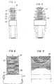
- the high-voltage bushing shown in Fig. 1 is manufactured in such a way that a mandrel 1, e.g. can be formed by a metal sleeve, the insulating material web 2 and the thin plastic film 3 are wound at the same time.
- the insulating material web 2 and the thin plastic film are guided in such a way that the insulating material web 2 runs onto the mandrel 1 below the thin plastic film 3 and is thus pressed evenly and firmly against the mandrel 1 by the thin plastic film while avoiding wrinkling;
- the thin plastic film 3 is wrapped with tension under elastic stretch.
- the high-voltage bushing 4 shown in FIG. 1 can be used in such a way that, for example, a conductor connected to high voltage is passed through the through hole formed by the metal sleeve or by the mandrel 1, while the metal foil 5 can be at ground potential, for example grounded housing.
- the exemplary embodiment of a high-voltage bushing shown in FIG. 2 is produced in such a way that the insulating material web 11 and, at the same time, the thin plastic film 12 is wound on a mandrel 10 under tension with stretch.
- care is taken that the next turn in each case from the insulating material sheet 11 and the thin plastic film 12 is applied with a lateral offset, so that the high-voltage bushing 13 has the funnel-shaped shape which can be seen in FIG. 2 after its completion.
- the high-voltage bushing 13 On its outer circumference, the high-voltage bushing 13 is in turn surrounded by a foil 14 made of metal, with which it can in turn be connected, for example, to a grounded housing.
- the mandrel 10 can be penetrated by a primary conductor when using the high-voltage bushing 13.
- the exemplary embodiment of a high-voltage bushing 20 according to FIG. 3 is produced in principle in exactly the same way as that according to FIGS. 1 and 3, only with the difference that here an insulating material web 22 and a thin plastic film 23 are wound with a decreasing width in steps, so that a high-voltage bushing is formed with a gradually decreasing length towards the outside.
- the exemplary embodiment according to FIG. 4 is produced in such a way that an insulating material web 31 and a thin plastic film 32 are wound simultaneously on a mandrel 30 in the form of a metal sleeve.
- the insulating material sheet 31 here has a smaller width than the thin plastic film 32, so that because of the central winding of the insulating material sheet 31 and the thin plastic film 32, which is increasing in the radial direction, a high-voltage bushing 33 is formed, in which the ends 34 and 35 of the thin material projecting on both end faces Plastic film form 32 screens that increase the electrical strength of the high-voltage bushing.
- a foil 36 made of metal is again provided on the outer circumference of the high-voltage bushing 33.
- the screens 37 are formed by the insulating material web 38, which varies in width over the height of the winding.
- the high-voltage bushing according to FIG. 6 is produced in exactly the same way with respect to the winding of an insulating material sheet and a thin plastic film as can be seen from FIG. 1.
- 40 metal foils 41 and 42 are wrapped in the manufacture of this high-voltage bushing, the width of which changes over the winding height in such a way that the contour of an electrode controlling the electric field is formed in each case.
- the bushing 40 is supported by a mandrel 43 which, when used, can be penetrated by a high-voltage primary conductor; the bushing is held on the outside in a grounded housing 44, which can be, for example, the metal tube of a metal-encapsulated high-voltage switchgear.
- the metal foil 50 is dimensioned to decrease in width from the outside inwards to achieve a better electrode contour, so that a good approximation to a predetermined contour can be achieved .
- a conical high-voltage bushing 60 for the manufacture of which an insulating material sheet 62 and, at the same time, a thin plastic film 63 are wound onto a mandrel 61. While the insulating material web 62 from the inside to the outside in its width according to the required shape of the high chip Implementation decreases, the width of the thin plastic film 63 is not changed, so it grows radially from the inside to the outside with a constant width.
- the outside of the high-voltage bushing is in turn surrounded by a foil 64 made of metal, with which it can be connected, for example, by contacting a housing that is grounded, for example.
- the conical high-voltage bushing 70 shown in FIG. 9 is provided with metal foils 71 which bring about capacitive control.
- the metal foils 71 are co-wrapped in the manufacture of the high-voltage bushing, with the application of the plastic film 73, which is relatively narrow in comparison to the insulating material web 72, to ensure that the latter is wound spirally and encompasses the metal foils 71 and thereby fixes their position within the high-voltage bushing 70.
- the conical high-voltage bushing according to FIG. 10 is in turn provided with metal foils 80, which are co-wrapped when the insulating material sheet 81 and the thin plastic film 82 are wound up.
- the thin plastic film 82 is not wound up spirally here, but instead is wrapped with increasing radial spacing over the length of the high-voltage bushing 83.
- the axial distance between the plastic foils 82 is determined by the length of the metal foils 80, because these should be held in place by the thin plastic foils 82 in the area of their two ends.
- the high-voltage bushing therefore consists of individual parts 90, 91 and 92, which are wound on a mandrel 93.
- Each part 90 to 92 is in each case manufactured in such a way that the thin plastic film 95 is simultaneously wound on the mandrel 93 together with an insulating material sheet 94 under tension with stretch, the thin plastic film 95 being relatively narrow in comparison to the insulating material sheet and being radially growing is.
- the insulating material web 94 is wound with a lateral offset, so that each part 90 to 92 represents a funnel-shaped partial feedthrough, which complement one another to carry out a relatively large length.
- each partial bushings 90 to 92 impregnated with insulating gas, but gaps 97 and 98 are also filled with insulating gas, so that a relatively high-length insulation bushing of relatively high length is formed.
- the invention proposes a method for producing a high-voltage bushing with which an electrically and mechanically fixed bushing can be achieved in a simple manner.
Landscapes
- Engineering & Computer Science (AREA)
- Mechanical Engineering (AREA)
- Insulators (AREA)
- Insulating Bodies (AREA)
- Winding Of Webs (AREA)
Description
- Die Erfindung geht von einem Verfahren zum Herstellen einer Hochspannungsdurchführung aus, bei dem zusammen mit einer Isolierstoffbahn eine vergleichsweise dünne Kunststoffolie unter Bildung jeweils gemeinsamer Windungen auf einen Dorn gewickelt wird.
- Bei einem bekannten Verfahren dieser Art (DE-AS 1 515 471, insbesondere Fig. 1) wird als lsolierstoffbahn ein Papierband verwendet, das bevorzugt aus Kreppapier besteht. Das Papier soll saugfähig sein, weil es zusammen mit einer dünneren Kunststoffolie gewickelt wird, die unter der Einwirkung von Wärme und Druck schmilzt und teilweise in die anliegende Papierbahn eindringt. Die so hergestellte Hochspannungsdurchführung hat den Vorteil, dass sie auch hohen Betriebstemperaturen ausgesetzt werden kann.
- Bei einem anderen bekannten Verfahren zum Herstellen einer Hochspannungsdurchführung (DE-AS 1 056218) werden nebeneinander mehrere Bahnen aus Isolierstoff, beispielsweise Papier oder Filmmaterial, spiralig aufgewickelt, und zwar in der Weise, dass die Bahnen gleichzeitig in zwei Lagen gewickelt werden; die eine Lage überdeckt jeweils die Stossstellen der anderen Lage. Die Isolierstoffbahnen für die beiden Lagen weisen unter anderem eine unterschiedliche Dikke auf. Es lässt sich ein fester Wickel bilden, so dass ein Durchbiegen des Dornes weitgehend vermieden ist.
- Schwierigkeiten entstehen bei der Herstellung von Hochspannungsdurchführungen aus einer Isolierstoffbahn mit gleichzeitig eingewickelter dünner Kunststoffolie vor allem, im Hinblick auf die Vermeidung von Falten, die sich beim Aufwikkeln der Isolierstoffbahn leicht bilden können. Dies ist darauf zurückzuführen, dass sich die Isolierstoffbahn wegen ihrer meist verhältnismässig grossen Dicke und Breite ohne Falten in der Regel nicht auf einen Dorn aufwickeln lässt. Falten wiederum führen zu Spaltenbildungen innerhalb der Hochspannungsdurchführung und verursachen dadurch isolationstechnische Schwachstellen in der Durchführung.
- Der Erfindung liegt die Aufgabe zugrunde, ein Verfahren zum Herstellen einer Hochspannungsdurchführung mit gemeinsamer Aufwicklung einer Isolierstoffbahn und einer dünnen Kunststoffolie anzugeben, mit dem sich ein weitestgehend falten- und damit auch weitestgehend spaltenfreier Aufbau der Durchführung erreichen lässt.
- Zur Lösung dieser Aufgabe wird bei einem Verfahren der eingangs angegebenen Art erfindungsgemäss die dünne Kunststoffolie oberhalb der lsolierstoffbahn auf den Dorn geführt und unter Zug mit elastischer Dehnung gewickelt.
- Ein wesentlicher Vorteil des erfindungsgemässen Verfahrens besteht darin, dass sich die dünne Kunststoffolie aufgrund des auf sie ausgeübten Zuges gleichmässig an die darunter befindliche bzw. auf den Dorn auflaufende Isolierstoffbahn anlegt und diese damit ihrerseits ohne Falten an den Dorn bzw. die darunterliegenden Windungen aus der Isolierstoffbahn und der dünnen Kunststoffolie andrückt. Die Dehnung der dünnen Kunststoffolie ist dabei unter Aufwendung einer vergleichsweise geringen Zugspannung erreichbar, weil die Kunststoffolie verhältnismässig dünn ist. Die dünne Kunststoffolie dient bei dem erfindungsgemässen Verfahren also gewissermassen als Zug- bzw. Spannfolie. Ein weiterer Vorteil des erfindungsgemässen Verfahrens ist darin zu sehen, dass durch die unter Zug mit Dehnung aufgewickelte Kunststoffolie eine verhältnismässig feste Hochspannungsdurchführung erzielbar ist, so dass die so hergestellte Hochspannungsdurchführung durchaus als Trage- oder Stützkörper in elektrischen Anlagen eingesetzt werden kann, ohne dass es dazu zusätzlicher mechanischer Einrichtungen zur Stützung der Hochspannungsdurchführung bedarf. Als zusätzlicher Vorteil ist die verhältnismässig einfache Durchführbarkeit des erfindungsgemässen Verfahrens anzusehen, weil es keiner Wärmebehandlung der Hochspannungsdurchführung bedarf, um ihr eine gute mechanische Festigkeit zu verleihen; allein durch das Mitwickeln der dünnen Kunststoffolie unter Zug mit Dehnung wird eine mechanisch feste Hochspannungsdurchführung erreicht.
- Es ist zwar bereits bei einem Verfahren zum Herstellen einer Hochspannungsdurchführung bekannt (US-A-3 397 098), eine Bahn aus Isolierstoff unter Zug mit elastischer Dehnung zu wickeln, jedoch handelt es sich bei dieser Bahn um eine z.B. gewellte Isolierstoffbahn, auf die beispielsweise eine glatte Kunststoffolie mit derartiger Stärke gewickelt wird, dass sie die Isolierstoffbahn ohne Deformation tragen kann. Es kann dann jeweils im Bereich der Isolierstoffbahn Giessharz in die Durchführung eingebracht werden, um einen festen Aufbau zu erzielen, wobei sich die Isolierstoffbahn den Volumenänderungen des Giessharzes beim Aushärten anpasst.
- Zur Durchführung des erfindungsgemässen Verfahrens können eine Isolierstoffbahn und eine dünne Kunststoffolie mit übereinstimmender Breite benutzt werden. Durch Aufwickeln der Isolierstoffbahn und der dünnen Kunststoffolie in radialer Richtung vom Dorn anwachsend lässt sich dann in einfacher Weise eine scheibenförmige Hochspannungsdurchführung herstellen, wie sie beispielsweise für metallgekapselte Hochspannungsschaltanlagen benötigt wird.
- Es kann aber auch vorteilhaft sein, eine Isolierstoffbahn und eine dünne Kunststoffolie mit sich unterscheidender Breite zu verwenden. Dabei kann sowohl die Isolierstoffbahn schmaler als die dünne Kunststoffolie sein, oder es kann auch umgekehrt die dünne Kunststoffolie schmaler als die Isolierstoffbahn sein. Werden die Isolierstoffbahn und die dünne Kunststoffolie mittig aufeinander und radial anwachsend auf den Dorn gewickelt, dann entsteht eine Hochspannungsdurchführung, bei der die jeweils breitere Isolierbahn an beiden Stirnseiten hervorsteht und gewissermassen Schirme bildet, die die Überschlagsfestigkeit erheblich erhöhen.
- Es ist aber auch möglich, die Isolierstoffbahn und die dünne Kunststoffolie nicht mittig aufeinander zu wickeln, sondern mit seitlichem Versatz, so dass dann eine trichterförmige Hochspannungsdurchführung gebildet wird. Bei dieser trichterförmigen Durchführung können auch wieder seitliche Schirme durch überstehende Teile der Isolierstoffbahn bzw. der dünnen Kunststoffolie gebildet sein, je nachdem, ob die Isolierstoffbahn breiter als die dünne Kunststoffolie ist oder umgekehrt.
- Eine faltenfreie und feste Hochspannungsdurchführung in trichterförmiger Ausbildung lässt sich auch dann erreichen, wenn gemäss einer Weiterbildung des erfindungsgemässen Verfahrens die Isolierstoffbahn mit seitlichem Versatz und die dünne Kunststoffolie radial anwachsend gewickelt werden. In diesem Falle ist die dünne Kunststoffolie schmaler als die Isolierstoffbahn, sorgt aber trotzdem für einen mechanisch festen Aufbau der Hochspannungsdurchführung. Bei einer solchen Hochspannungsdurchführung ist die Imprägnierbarkeit verbessert, so dass beispielsweise Isoliergas gut in den Wickel eindringen kann, wodurch die elektrische Festigkeit weiter erhöht wird.
- Wie an sich bekannt (vgl. z.B. DE-AS 1 515471) können mit der Isolierstoffbahn und der dünnen Kunststoffolie bei der Durchführung des erfindungsgemässen Verfahrens Metallfolien miteingewickelt werden. Die Metallfolien können dabei im Hinblick auf die angestrebte elektrische Festigkeit unterschiedliche oder sich ändernde Breite aufweisen.
- Gemäss einer Weiterbildung des erfindungsgemässen Verfahrens kann zur Herstellung einer konusförmig ausgebildeten Hochspannungsdurchführung die dünne Kunststoffolie an der stärksten Stelle der Hochspannungsdurchführung radial anwachsend gewickelt werden, wobei bei einer geeignet bemessenen Breite der dünnen Kunststoffolie allein dadurch eine mechanisch feste Hochspannungsdurchführung erzielbar ist.
- Zwar etwas aufwendiger in der Ausführung, aber mit dem Ergebnis einer Hochspannungsdurchführung mit einem mechanisch besonders festen Aufbau, lässt sich bei einer anderen Weiterbildung des erfindungsgemässen Verfahrens eine konusförmig ausgebildete Hochspannungsdurchführung herstellen, indem die dünne Kunststofffolie spiralförmig über die Länge der Hochspannungsdurchführung gewickelt wird. Handelt es sich bei der Hochspannungsdurchführung um eine gesteuerte Durchführung, dann ist die dünne Kunststoffolie vorteilhafterweise die Metallfolie umfassend gewickelt und verhindert dadurch ein Verschieben der Metallfolien innerhalb der Hochspannungsdurchführung.
- Bei einer anderen Variante des erfindungsgemässen Verfahrens zur Herstellung einer konusförmig ausgebildeten Hochspannungsdurchführung wird über die Länge der Hochspannungsdurchführung an mehreren Stellen die dünne Kunststoffolie radial anwachsend gewickelt. Die dünne Kunststoffolie ist dabei verhältnismässig schmal und kann daher mit besonders hohem Zug unter Bildung einer mechanisch festen Durchführung gewickelt werden. Bei dieser Variante des erfindungsgemässen Verfahrens wird in dem Falle, in dem eine gesteuerte Hochspannungsdurchführung hergestellt werden soll, die dünne Kunststoffolie in einem von der Breite der Metallfolie bestimmten Abstand voneinander radial anwachsend gewickelt, so dass die einzelnen Metallfolien im Bereich ihrer stirnseitigen Enden jeweils in die dünne Kunststoffolie miteingewickelt und daher in ihrer Lage fixiert sind.
- Es ist ferner vorteilhaft, bei einer konusförmig ausgebildeten Hochspannungsdurchführung zur Verbesserung der mechanischen Festigkeit und Halterung der Metallfolien sowie zum Schutz der Folienränder aussen auf den konusförmigen Teil der Durchführung Ringe oder kurze Schläuche aus Schrumpf-Material aufzubringen und einer Wärmebehandlung zu unterwerfen. Bevorzugt sind die Ringe oder Schläuche auf den treppenförmigen Absätzen des konusförmigen Teils angeordnet.
- Bei dem erfindungsgemässen Verfahren kann als Isolierstoffbahn eine Papierbahn verwendet werden; es kommt aber auch eine verhältnismässig dicke Kunststoffolie in Frage.
- Die dicke Kunststoffolie ist vorteilhafterweise perforiert oder weist eine Struktur z.B. nach Art eines Rautenmusters auf. Dies hat den Vorteil, dass im Falle einer Imprägnierung der Hochspannungsdurchführung mit einem Isoliergas, beispielsweise SFa, die Imprägnierbarkeit verbessert wird. Dieser Vorteil ergibt sich auch, wenn als Isolierstoffbahn ein Gewebe-, Geflecht- oder Vliesband verwendet wird.
- Es ist ferner vorteilhaft, wenn auch die Metallfolie aufgerauht oder perforiert ist, weil auch dadurch die Imprägnierbarkeit der Hochspannungsdurchführung mit einem Isoliergas verbessert wird.
- Ferner kann es vorteilhaft sein, als dünne Kunststoffolie eine Schrumpf-Folie zu verwenden, die bei Wärmeeinwirkung zusammenschrumpft und dadurch einen ausserordentlichen festen Aufbau der Hochspannungsdurchführung ergibt.
- Zur Erläuterung des erfindungsgemässen Verfahrens ist in
- Fig. 1 eine scheibenförmige Hochspannungsdurchführung gemäss dem erfindungsgemässen Verfahren in einem Schnitt und in einer Seitenansicht, in
- Fig. 2 eine trichterförmige Hochspannungsdurchführung in einem Schnitt, in
- Fig. 3 ein Schnitt durch eine scheibenförmige Hochspannungsdurchführung mit gestufter Länge, in
- Fig. 4 eine weitere Hochspannungsdurchführung gemäss einer Variante des erfindungsgemässen Verfahrens im Schnitt, in
- Fig. 5 eine andere Hochspannungsdurchführung mit seitlichen Schirmen, in
- Fig. 6 eine weitere Hochspannungsdurchführung nach dem erfindungsgemässen Verfahren mit eingebetteten Metallfolien, in
- Fig. 7 ein zusätzliches Ausführungsbeispiel mit ebenfalls eingebetteten Metallfolien, in
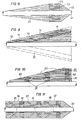
- Fig. 8 ein Ausführungsbeispiel einer Hochspannungsdurchführung mit konusförmiger Gestalt, in
- Fig. 9 ein Ausführungsbeispiel einer konusförmigen Hochspannungsdurchführung mit kapazitiver Steuerung, in
- Fig. 10 ein anderes Ausführungsbeispiel einer konusförmigen, kapazitiv gesteuerten Hochspannungsdurchführung und in
- Fig. 11 ein Ausführungsbeispiel einer Hochspannungsdurchführung aus mehreren Einzelteilen wiedergegeben.
- Die in Fig. 1 dargestellte Hochspannungsdurchführung ist in der Weise hergestellt, dass auf einen Dorn 1, der z.B. von einer Metallhülse gebildet sein kann, gleichzeitig die Isolierstoffbahn 2 und die dünne Kunststoffolie 3 aufgewickelt sind. Dabei sind die Isolierstoffbahn 2 und die dünne Kunststoffolie so geführt, dass die Isolierstoffbahn 2 jeweils unterhalb der dünnen Kunststoffolie 3 auf den Dorn 1 aufläuft und somit von der dünnen Kunststoffolie unter Vermeidung einer Faltenbildung gleichmässig und fest an den Dorn 1 gedrückt wird; zu diesem Zwecke ist die dünne Kunststoffolie 3 mit Zug unter elastischer Dehnung gewickelt. Dadurch wird gleichzeitig die Luft zwischen der Isolierstoffbahn 2 und der Kunststoffolie 3 weitgehend entfernt, so dass zusätzliche Verfestigung durch Adhäsions- und Reibungskräfte entsteht. Durch Aufbringen mehrerer Windungen aus der Isolierstoffbahn 2 und der Kunststoffolie 3 entsteht eine scheibenförmige Durchführung 4, die an ihrem äusseren Umfange im dargestellten Ausführungsbeispiel durch eine Metallfolie 5 abgeschlossen ist.
- Die in der Fig. 1 dargestellte Hochspannungsdurchführung 4 kann in der Weise eingesetzt werden, dass beispielsweise durch das von der Metallhülse bzw. von dem Dorn 1 gebildete Durchgangsloch ein an Hochspannung liegender Leiter geführt wird, während die Metallfolie 5 auf Erdpotential liegen kann, beispielsweise an einem geerdeten Gehäuse anliegen kann.
- Das in der Fig. 2 dargestellte Ausführungsbeispiel einer Hochspannungsdurchführung ist in der Weise hergestellt, dass auf einen Dorn 10 wiederum die Isolierstoffbahn 11 und darauf gleichzeitig die dünne Kunststoffolie 12 unter Zug mit Dehnung gewickelt ist. Dabei ist beim Herstellen der Durchführung 13 darauf geachtet, dass die jeweils nächste Windung aus der Isolierstoffbahn 11 und der dünnen Kunststoffolie 12 mit seitlichem Versatz aufgebracht wird, so dass die Hochspannungsdurchführung 13 nach ihrer Fertigstellung die aus der Fig. 2 erkennbare, trichterförmige Gestalt aufweist. An ihrem äusseren Umfange ist die Hochspannungsdurchführung 13 wiederum mit einer Folie 14 aus Metall umgeben, mit der sie wiederum beispielsweise an ein geerdetes Gehäuse angeschlossen sein kann. Der Dorn 10 kann beim Einsatz der Hochspannungsdurchführung 13 von einem Primärleiter durchsetzt sein.
- Das Ausführungsbeispiel einer Hochspannungsdurchführung 20 nach Fig. 3 ist im Prinzip genauso hergestellt wie das nach den Fig. 1 und 3, nur mit dem Unterschied, dass hier auf einen Dorn 21 eine Isolierstoffbahn 22 und eine dünne Kunststoffolie 23 mit gestuft abnehmender Breite gewickelt sind, so dass eine Hochspannungsdurchführung mit nach aussen stufenweise abnehmender Länge gebildet ist.
- Das Ausführungsbeispiel nach Fig. 4 ist in der Weise hergestellt, dass auf einen Dorn 30 in Form einer Metallhülse wiederum eine Isolierstoffbahn 31 und darauf eine dünne Kunststoffolie 32 gleichzeitig gewickelt sind. Die Isolierstoffbahn 31 hat hier eine geringere Breite als die dünne Kunststoffolie 32, so dass wegen des mittigen und in radialer Richtung anwachsenden Aufwickelns von Isolierstoffbahn 31 und dünner Kunststoffolie 32 eine Hochspannungsdurchführung 33 entsteht, bei der die an beiden Stirnseiten herausragenden Enden 34 und 35 der dünnen Kunststoffolie 32 Schirme bilden, die die elektrische Festigkeit der Hochspannungsdurchführung vergrössern. Am äusseren Umfange der Hochspannungsdurchführung 33 ist wiederum eine Folie 36 aus Metall vorgesehen.
- Bei dem Ausführungsbeispiel nach Fig. 5 sind die Schirme 37 durch die Isolierstoffbahn 38 gebildet, die in ihrer Breite über die Höhe des Wickels unterschiedlich ist.
- Die Hochspannungsdurchführung nach Fig. 6 ist hinsichtlich des Aufwickelns einer Isolierstoffbahn und einer dünnen Kunststoffolie genauso hergestellt, wie es aus der Fig. 1 ersichtlich ist. Zusätzlich sind bei der Herstellung dieser Hochspannungsdurchführung 40 Metallfolien 41 und 42 miteingewickelt, deren Breite sich über die Wickelhöhe derart verändert, dass jeweils die Kontur einer das elektrische Feld steuernden Elektrode gebildet wird.
- Die Durchführung 40 ist von einem Dorn 43 getragen, der bei ihrem Einsatz von einem an Hochspannung liegenden Primärleiter durchsetzt sein kann; aussen ist die Durchführung in einem geerdeten Gehäuse 44 gehalten, bei dem es sich beispielsweise um das Metallrohr einer metallgekapselten Hochspannungsschaltanlage handeln kann.
- Die Hochspannungsdurchführung nach Fig. 7 unterscheidet sich von der nach Fig. 6 nur insofern, als hier zur Erzielung einer besseren Elektrodenkontur die Metallfolie 50 in ihrer Breite von aussen nach innen schwächer abnehmend bemessen ist, so dass eine gute Annäherung an eine vorgegebene Kontur erreichbar ist.
- Bei dem Ausführungsbeispiel nach Fig. 8 handelt es sich um eine konusförmig ausgebildete Hochspannungsdurchführung 60, zu deren Herstellung auf einen Dorn 61 eine Isolierstoffbahn 62 und gleichzeitig damit eine dünne Kunststoffolie 63 aufgewickelt sind. Während die Isolierstoffbahn 62 von innen nach aussen in ihrer Breite entsprechend der erforderlichen Gestalt der Hochspannungsdurchführung abnimmt, ist die dünne Kunststoffolie 63 in ihrer Breite nicht verändert, wächst also von innen nach aussen mit gleichbleibender Breite radial an. Aussen ist die Hochspannungsdurchführung wiederum von einer Folie 64 aus Metall umgeben, mit der sie im Einsatzfalle unter Kontaktgabe mit einem beispielsweise geerdeten Gehäuse verbunden werden kann.
- Die in der Fig. 9 dargestellte konusförmig ausgebildete Hochspannungsdurchführung 70 ist mit Metallfolien 71 versehen, die eine kapazitive Steuerung bewirken. Die Metallfolien 71 sind bei der Herstellung der Hochspannungsdurchführung miteingewickelt, wobei bei der Aufbringung der im Vergleich zur Isolierstoffbahn 72 verhältnismässig schmalen Kunststoffolie 73 darauf geachtet ist, dass letztere spiralförmig aufgewickelt ist und die Metallfolien 71 umfasst und dadurch in ihrer Lage innerhalb der Hochspannungsdurchführung 70 fixiert.
- Die konusförmig ausgebildete Hochspannungsdurchführung nach Fig. 10 ist wiederum mit Metallfolien 80 versehen, die beim Aufwickeln der Isolierstoffbahn 81 und der dünnen Kunststoffolie 82 miteingewickelt sind. Die dünne Kunststoffolie 82 ist hier jedoch in Abweichung von der Ausführung nach Fig. 9 nicht spiralförmig aufgewickelt, sondern über die Länge der Hochspannungsdurchführung 83 jeweils in Abständen radial anwachsend miteingewickelt. Dabei ist der axiale Abstand der Kunststoffolien 82 durch die Länge der Metallfolien 80 bestimmt, weil diese im Bereich ihrer beiden Enden durch die dünne Kunststoffolien 82 festgehalten werden sollen.
- Bei dem Ausführungsbeispiel nach Fig. 11 handelt es sich um eine Hochspannungsdurchführung verhältnismässig grosser Länge. Die Hochspannungsdurchführung besteht daher aus einzelnen Teilen 90, 91 und 92, die auf einen Dorn 93 aufgewickelt sind. Jedes Teil 90 bis 92 ist jeweils in der Weise hergestellt, dass auf den Dorn 93 zusammen mit einer Isolierstoffbahn 94 gleichzeitig die dünne Kunststoffolie 95 unter Zug mit Dehnung aufgewickelt wird, wobei die dünne Kunststoffolie 95 im Vergleich zur Isölierstoffbahn verhältnismässig schmal ist und radial anwachsend miteingewickelt ist. Die Isolierstoffbahn 94 hingegen ist mit seitlichem Versatz gewickelt, so dass jeder Teil 90 bis 92 eine trichterförmig ausgebildete Teildurchführung darstellt, die sich zu einer Durchführung verhältnismässig grosser Länge ergänzen. Wird die Durchführung in einem Raum mit Isoliergas untergebracht, dann wird nicht nur jede Teildurchführung 90 bis 92 mit Isoliergas imprägniert, sondern es werden auch die Spalten 97 und 98 mit Isoliergas gefüllt, so dass eine isolationstechnisch feste Hochspannungsdurchführung verhältnismässig grosser Länge gebildet ist.
- Mit der Erfindung wird ein Verfahren zum Herstellen einer Hochspannungsdurchführung vorgeschlagen, mit dem sich in einfacher Weise eine elektrisch und mechanisch feste Durchführung erreichen lässt.
Claims (19)
Priority Applications (1)
| Application Number | Priority Date | Filing Date | Title |
|---|---|---|---|
| AT79103199T ATE3173T1 (de) | 1978-09-29 | 1979-08-29 | Verfahren zum herstellen einer hochspannungsdurchfuehrung. |
Applications Claiming Priority (2)
| Application Number | Priority Date | Filing Date | Title |
|---|---|---|---|
| DE2843081 | 1978-09-29 | ||
| DE19782843081 DE2843081A1 (de) | 1978-09-29 | 1978-09-29 | Verfahren zum herstellen einer hochspannungsdurchfuehrung |
Publications (2)
| Publication Number | Publication Date |
|---|---|
| EP0009622A1 EP0009622A1 (de) | 1980-04-16 |
| EP0009622B1 true EP0009622B1 (de) | 1983-04-27 |
Family
ID=6051261
Family Applications (1)
| Application Number | Title | Priority Date | Filing Date |
|---|---|---|---|
| EP79103199A Expired EP0009622B1 (de) | 1978-09-29 | 1979-08-29 | Verfahren zum Herstellen einer Hochspannungsdurchführung |
Country Status (4)
| Country | Link |
|---|---|
| EP (1) | EP0009622B1 (de) |
| JP (1) | JPS5546499A (de) |
| AT (1) | ATE3173T1 (de) |
| DE (1) | DE2843081A1 (de) |
Families Citing this family (2)
| Publication number | Priority date | Publication date | Assignee | Title |
|---|---|---|---|---|
| DE3226057A1 (de) * | 1982-07-12 | 1984-01-12 | Siemens AG, 1000 Berlin und 8000 München | Hochspannungsdurchfuehrung mit einem gewickelten isolationskoerper |
| CH674351A5 (de) * | 1988-01-18 | 1990-05-31 | Guido Rossi Dipl Ing |
Citations (1)
| Publication number | Priority date | Publication date | Assignee | Title |
|---|---|---|---|---|
| DE1515471B1 (de) * | 1964-04-21 | 1969-12-11 | The Bushing Co Ltd | Verfahren zur Herstellung von Wickelisolatoren |
Family Cites Families (11)
| Publication number | Priority date | Publication date | Assignee | Title |
|---|---|---|---|---|
| FR626101A (fr) * | 1925-12-11 | 1927-08-30 | Siemens Schuckertwerke Gmbh | Isolateur en forme de tube ou massue |
| FR868148A (fr) * | 1940-08-19 | 1941-12-18 | Comp Generale Electricite | Procédé pour renforcer localement l'isolant d'un câble électrique et isolant obtenu par la mise en ceuvre de ce procédé |
| FR1056904A (fr) * | 1951-01-20 | 1954-03-03 | Thomson Houston Comp Francaise | Procédé et dispositifs perfectionnés d'isolation électrique |
| DE1056217B (de) * | 1952-04-15 | 1959-04-30 | Siemens Ag | Wellenfuehrung zur leitungsgebundenen Fortfuehrung elektromagnetischer Wellen |
| DE1056218B (de) * | 1953-09-15 | 1959-04-30 | Dielektra Ag | Compound- oder oelimpraegnierte, vorzugsweise papierisolierte Hochspannungsdurchfuehrung grosser Laenge, insbesondere Kondensatordurchfuehrung |
| DE1100745B (de) * | 1959-08-12 | 1961-03-02 | Comp Generale Electricite | In vertikaler oder angenaehert vertikaler Lage stehende Durchfuehrung fuer elektrische Hochspannungskabel |
| FR1288329A (fr) * | 1961-03-24 | 1962-03-24 | Reyrolle A & Co Ltd | Procédé d'isolement de conducteurs haute tension et éléments isolants réalisés selon ce procédé |
| US3397098A (en) * | 1962-03-15 | 1968-08-13 | Moser Glaser & Co Ag | Method of making insulating bodies |
| GB979833A (en) * | 1963-07-26 | 1965-01-06 | Standard Telephones Cables Ltd | Electric cable joints |
| GB1091135A (en) * | 1964-10-05 | 1967-11-15 | Sumitomo Electric Industries | Improvements in or relating to the moulding of stress cones or condenser bushings on cables |
| US3567845A (en) * | 1970-01-16 | 1971-03-02 | Gen Cable Corp | Insulated cable joint |
-
1978
- 1978-09-29 DE DE19782843081 patent/DE2843081A1/de not_active Ceased
-
1979
- 1979-08-29 EP EP79103199A patent/EP0009622B1/de not_active Expired
- 1979-08-29 AT AT79103199T patent/ATE3173T1/de not_active IP Right Cessation
- 1979-09-28 JP JP12523579A patent/JPS5546499A/ja active Granted
Patent Citations (1)
| Publication number | Priority date | Publication date | Assignee | Title |
|---|---|---|---|---|
| DE1515471B1 (de) * | 1964-04-21 | 1969-12-11 | The Bushing Co Ltd | Verfahren zur Herstellung von Wickelisolatoren |
Also Published As
| Publication number | Publication date |
|---|---|
| DE2843081A1 (de) | 1980-04-10 |
| ATE3173T1 (de) | 1983-05-15 |
| JPS5546499A (en) | 1980-04-01 |
| JPS6217810B2 (de) | 1987-04-20 |
| EP0009622A1 (de) | 1980-04-16 |
Similar Documents
| Publication | Publication Date | Title |
|---|---|---|
| DE2312670A1 (de) | Verbindung fuer elektrische kabel und verfahren zu ihrer herstellung | |
| DE2445019C3 (de) | Transformatorwicklung mit bandförmigem Leiter | |
| EP0009622B1 (de) | Verfahren zum Herstellen einer Hochspannungsdurchführung | |
| EP0219068A2 (de) | Im Filament-Winding-Verfahren hergestelltes Isolierstoffrohr | |
| DE2359905A1 (de) | Elektroden fuer elektrische akkumulatoren | |
| WO2017042013A1 (de) | Verfahren zur herstellung einer formspule für eine elektrische maschine mittels flachdraht | |
| DE961903C (de) | Biegsames isoliertes elektrisches Kabel | |
| EP0389892B1 (de) | Transformator | |
| DE548526C (de) | Spinnduese fuer Kunstseide und Verfahren zu ihrer Herstellung | |
| EP0161265B1 (de) | Verfahren und vorrichtung für die herstellung eines schraubenförmigen schirmbandes und eines freileitungsisolators | |
| WO2007057251A1 (de) | Glimmerverstärkte isolation | |
| DE2733024C2 (de) | Schichtisolation für toroidale Körper von Hochspannung führenden elektrischen Bauteilen sowie Verfahren und Vorrichtung zu deren Herstellung | |
| DE2628523C3 (de) | Hochspannungswicklung | |
| AT150846B (de) | Zusammengesetzter elastischer Faden. | |
| DE1438284C (de) | Isolierter Feldpol | |
| AT267657B (de) | Erregerspule, insbesondere für Relais | |
| DE2843079A1 (de) | Hochspannungsdurchfuehrung | |
| DE1950921C (de) | Verfahren zum Herstellen einer Umhüllung aus Isoliermaterial für Energiekabelverbindungen | |
| DE954529C (de) | Hochfrequenz-Schichtenleiter aus abwechselnden duennen Metall- und Isolierschichten | |
| DE2053075C3 (de) | Verfahren zur Herstellung einer aus Isolierstoff bestehenden Abstandshalterung für koaxiale Hochfrequenzkabel | |
| DE228309C (de) | ||
| DE2060299C3 (de) | EndenabschluB mit einem gewickelten Oeflektor für Hochspannungskabel | |
| CH619080A5 (de) | ||
| DE3444966A1 (de) | Wickelband, damit bewickelter ringkern und wickelverfahren | |
| DE69733474T2 (de) | Isolierkernkörper von hochspannungswiderstandsvorrichtung |
Legal Events
| Date | Code | Title | Description |
|---|---|---|---|
| PUAI | Public reference made under article 153(3) epc to a published international application that has entered the european phase |
Free format text: ORIGINAL CODE: 0009012 |
|
| AK | Designated contracting states |
Designated state(s): AT BE CH GB IT SE |
|
| 17P | Request for examination filed |
Effective date: 19810122 |
|
| R17P | Request for examination filed (corrected) |
Effective date: 19800806 |
|
| ITF | It: translation for a ep patent filed | ||
| GRAA | (expected) grant |
Free format text: ORIGINAL CODE: 0009210 |
|
| AK | Designated contracting states |
Designated state(s): AT BE CH GB IT SE |
|
| REF | Corresponds to: |
Ref document number: 3173 Country of ref document: AT Date of ref document: 19830515 Kind code of ref document: T |
|
| PGFP | Annual fee paid to national office [announced via postgrant information from national office to epo] |
Ref country code: SE Payment date: 19830731 Year of fee payment: 5 |
|
| PGFP | Annual fee paid to national office [announced via postgrant information from national office to epo] |
Ref country code: AT Payment date: 19830804 Year of fee payment: 5 |
|
| PLBI | Opposition filed |
Free format text: ORIGINAL CODE: 0009260 |
|
| 26 | Opposition filed |
Opponent name: MESSWANDLER-BAU GMBH Effective date: 19840124 |
|
| PLAB | Opposition data, opponent's data or that of the opponent's representative modified |
Free format text: ORIGINAL CODE: 0009299OPPO |
|
| PG25 | Lapsed in a contracting state [announced via postgrant information from national office to epo] |
Ref country code: GB Effective date: 19840829 Ref country code: AT Effective date: 19840829 |
|
| PG25 | Lapsed in a contracting state [announced via postgrant information from national office to epo] |
Ref country code: SE Effective date: 19840830 |
|
| R26 | Opposition filed (corrected) |
Opponent name: MWB MESSWANDLER-BAU GMBH Effective date: 19840124 |
|
| PGFP | Annual fee paid to national office [announced via postgrant information from national office to epo] |
Ref country code: CH Payment date: 19841217 Year of fee payment: 6 |
|
| PGFP | Annual fee paid to national office [announced via postgrant information from national office to epo] |
Ref country code: BE Payment date: 19841231 Year of fee payment: 6 |
|
| GBPC | Gb: european patent ceased through non-payment of renewal fee | ||
| RDAG | Patent revoked |
Free format text: ORIGINAL CODE: 0009271 |
|
| STAA | Information on the status of an ep patent application or granted ep patent |
Free format text: STATUS: PATENT REVOKED |
|
| GBPR | Gb: patent revoked under art. 102 of the ep convention designating the uk as contracting state | ||
| 27W | Patent revoked |
Effective date: 19890316 |
|
| REG | Reference to a national code |
Ref country code: CH Ref legal event code: PL |
|
| BERE | Be: lapsed |
Owner name: SIEMENS A.G. BERLIN UND MUNCHEN Effective date: 19890831 |
|
| EUG | Se: european patent has lapsed |
Ref document number: 79103199.0 Effective date: 19850612 |
|
| APAH | Appeal reference modified |
Free format text: ORIGINAL CODE: EPIDOSCREFNO |