EP0008781B1 - Radial aufweitbares Rohrdorn zum längsweisen Raffen von flexiblem Schlauchmaterial, insbesondere Kunstdarm für die Wurstherstellung - Google Patents
Radial aufweitbares Rohrdorn zum längsweisen Raffen von flexiblem Schlauchmaterial, insbesondere Kunstdarm für die Wurstherstellung Download PDFInfo
- Publication number
- EP0008781B1 EP0008781B1 EP79103223A EP79103223A EP0008781B1 EP 0008781 B1 EP0008781 B1 EP 0008781B1 EP 79103223 A EP79103223 A EP 79103223A EP 79103223 A EP79103223 A EP 79103223A EP 0008781 B1 EP0008781 B1 EP 0008781B1
- Authority
- EP
- European Patent Office
- Prior art keywords
- mandrel
- tubular
- tubular mandrel
- spring elements
- control member
- Prior art date
- Legal status (The legal status is an assumption and is not a legal conclusion. Google has not performed a legal analysis and makes no representation as to the accuracy of the status listed.)
- Expired
Links
Images
Classifications
-
- A—HUMAN NECESSITIES
- A22—BUTCHERING; MEAT TREATMENT; PROCESSING POULTRY OR FISH
- A22C—PROCESSING MEAT, POULTRY, OR FISH
- A22C13/00—Sausage casings
- A22C13/02—Shirring of sausage casings
Definitions
- the invention relates to a radially expandable tubular mandrel for longitudinal shirring of flexible hose material, in particular artificial casing for sausage production.
- a pipe mandrel is known from US-A-1 876 279.
- Pipe mandrels are used both in manual gathering and in mechanical gathering, in order to support the tube material in the formation of folds during gathering and to calibrate the caterpillar formed, for example on the filler neck of a sausage filling machine, with a view to its later attachment.
- the inward folds come into close contact with the surface of the mandrel, which makes it more difficult to pull the caterpillar off the mandrel, especially when gathering mechanically.
- the known radially expandable tubular mandrel attempts to solve this problem by dividing the tubular mandrel along two diametrically located joints into two tubular mandrel halves, which can be pressed apart across the entire circular cross-section by a rotatable spreader member extending over the entire length of the tube.
- a rotatable spreader member By rotating the expansion member by 90 ° from the expansion position, the tube halves can lie against one another with their longitudinal edges, as a result of which their diameter is reduced perpendicular to the parting plane.
- the diameter remains practically unchanged, so that the subsequent removal of the bead produced on the tubular mandrel is only made slightly easier.
- the object of the invention is to provide a radially expandable tubular mandrel, which allows an extremely light and at the same time damage-free removal of the shirred caterpillars due to the fact that it can be expanded or reduced in diameter on all sides.
- the invention thus creates a radially expandable tubular mandrel, the cross section of which is widened in all directions for the gathering process and is then adjusted by simply moving the control member into its narrowed or tapered state, which is smaller than the cross section of the gathered bead and thus enables the latter to be easily detached .
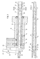
- 10 denotes a holder designed as a turned part, in the bore 12 of which is closed at the rear end by a cover 11, a centering sleeve 13 is inserted and fastened with screws 14.
- the centering sleeve 13 encloses a number, for example fourteen round wires made of spring steel, which are welded or soldered to the centering sleeve.
- the round wires 15 protrude far from the front end of the bore 12, for example up to one meter or possibly even further, and are welded or soldered with the free ends to a shoulder-shaped centering sleeve 16, the free end of which is tapered. In this way, the round wires 15 form a tubular mandrel for longitudinal shirring of flexible hose material, such as, in particular, artificial casing for sausage production.
- a head tube 17 is axially displaceable.
- the tapered front end 18 of the head tube 17 is slidably guided in the centering sleeve 16.
- the control tube 17 is guided in a bushing 19 within the centering sleeve 13 and protrudes with its rear end out of the holder 10, where it is gripped by an actuating lever 21 via a coupling 20, which is located at 22 on a bracket 23 is articulated, which is screwed to the bracket.
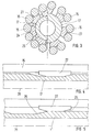
- the control tube 17 is ver preferably at equal longitudinal distances with a plurality of turns 24 to form conical cam surfaces 25 see. 4 and 5, they cooperate with cam surfaces 26 on cam members 27, which are welded or soldered to two round wires 15 each.
- a ring of such cam members 27 is arranged at the same intervals as the indentations 24 in the interior of the tubular mandrel formed by the round wires 15.
- the actuating lever 21 is pivoted counterclockwise.
- the indentations 24 fall into the area of the cam members 27, and these fall under the internal stress of the round wires 15 into the indentations 24 as shown in FIG. 4 and the left half of FIG. 3, as a result of which the effective cross section of the tubular mandrel is reduced Retaining its circular shape tapered.
- the tubular bead formed can be easily pulled off the tubular mandrel via its free end without resistance.
- the operating lever 21 is pivoted clockwise, whereby the head tube 17 is shifted to the left again.
- the cam surfaces 25 of the control tube 17 run on the cam surfaces 26 of the cam members 27 and spread the round wires 15 again over the latter into the expanded state of the tubular mandrel.
- the hollow control tube allows, in a known manner, the blowing of air under increased pressure into the intestine to be gathered, for which purpose, for example, a (not shown) hose connection can be provided at the end of the control tube 17.
Landscapes
- Life Sciences & Earth Sciences (AREA)
- Engineering & Computer Science (AREA)
- Wood Science & Technology (AREA)
- Zoology (AREA)
- Food Science & Technology (AREA)
- Processing Of Meat And Fish (AREA)
- Meat, Egg Or Seafood Products (AREA)
- Rigid Pipes And Flexible Pipes (AREA)
- Processing And Handling Of Plastics And Other Materials For Molding In General (AREA)
- Containers And Plastic Fillers For Packaging (AREA)
- Wire Processing (AREA)
- Farming Of Fish And Shellfish (AREA)
- Food-Manufacturing Devices (AREA)
- Shaping Of Tube Ends By Bending Or Straightening (AREA)
Priority Applications (1)
| Application Number | Priority Date | Filing Date | Title |
|---|---|---|---|
| AT79103223T ATE4160T1 (de) | 1978-09-01 | 1979-08-31 | Radial aufweitbares rohrdorn zum laengsweisen raffen von flexiblem schlauchmaterial, insbesondere kunstdarm fuer die wurstherstellung. |
Applications Claiming Priority (2)
| Application Number | Priority Date | Filing Date | Title |
|---|---|---|---|
| DE2838147 | 1978-09-01 | ||
| DE2838147A DE2838147C2 (de) | 1978-09-01 | 1978-09-01 | Radial aufweitbarer Rohrdorn zum längsweisen Raffen von flexiblem Schlauchmaterial, insbesondere Kunstdarm für die Wurstherstellung |
Publications (2)
| Publication Number | Publication Date |
|---|---|
| EP0008781A1 EP0008781A1 (de) | 1980-03-19 |
| EP0008781B1 true EP0008781B1 (de) | 1983-07-20 |
Family
ID=6048442
Family Applications (1)
| Application Number | Title | Priority Date | Filing Date |
|---|---|---|---|
| EP79103223A Expired EP0008781B1 (de) | 1978-09-01 | 1979-08-31 | Radial aufweitbares Rohrdorn zum längsweisen Raffen von flexiblem Schlauchmaterial, insbesondere Kunstdarm für die Wurstherstellung |
Country Status (13)
| Country | Link |
|---|---|
| EP (1) | EP0008781B1 (enExample) |
| JP (1) | JPS5753043B2 (enExample) |
| AT (1) | ATE4160T1 (enExample) |
| AU (1) | AU527594B2 (enExample) |
| CA (1) | CA1141587A (enExample) |
| DE (1) | DE2838147C2 (enExample) |
| DK (1) | DK189480A (enExample) |
| ES (1) | ES483797A1 (enExample) |
| FI (1) | FI792702A7 (enExample) |
| NO (1) | NO792807L (enExample) |
| PL (1) | PL125373B1 (enExample) |
| WO (1) | WO1980000525A1 (enExample) |
| YU (1) | YU212879A (enExample) |
Cited By (1)
| Publication number | Priority date | Publication date | Assignee | Title |
|---|---|---|---|---|
| CN103719225A (zh) * | 2013-11-29 | 2014-04-16 | 灵璧县新华肠衣有限责任公司 | 一种肠衣的制作装置 |
Families Citing this family (4)
| Publication number | Priority date | Publication date | Assignee | Title |
|---|---|---|---|---|
| JPS6075644U (ja) * | 1983-10-31 | 1985-05-27 | いすゞ自動車株式会社 | 内燃機関の圧力制限装置 |
| DE3637185A1 (de) * | 1986-10-31 | 1988-05-05 | Hoechst Ag | Verfahren und vorrichtung zum raffen von schlauchfoermigen huellen, insbesondere wursthuellen |
| US6264874B1 (en) * | 1999-04-22 | 2001-07-24 | Viskase Corporation | Method of controlling the diameter of a clear extruded tube |
| CN111771947B (zh) * | 2020-08-10 | 2021-06-18 | 青岛齐林智信自控技术有限公司 | 一种肠衣回气调压方法与装置 |
Family Cites Families (9)
| Publication number | Priority date | Publication date | Assignee | Title |
|---|---|---|---|---|
| US1616971A (en) * | 1926-08-20 | 1927-02-08 | Visking Corp | Preparation of sausage casings for stuffing |
| US1876279A (en) * | 1930-08-23 | 1932-09-06 | Visking Corp | Mandrel |
| US1933480A (en) * | 1932-02-18 | 1933-10-31 | Continental Can Co | Method of making containers |
| DE913033C (de) * | 1952-01-06 | 1954-06-08 | Richard Guigas | Vorrichtung zum Auskleiden einer Wursthuelle mit Speck |
| DE1177029B (de) * | 1959-01-07 | 1964-08-27 | Handtmann Albert | Fuellkopf fuer die Abdrehtuelle von Wurst-fuellmaschinen |
| US3203807A (en) * | 1962-03-12 | 1965-08-31 | Mayer & Co Inc O | Method and apparatus for forming a sausage meat product |
| NL300528A (enExample) * | 1962-11-16 | |||
| US3457588A (en) * | 1966-12-05 | 1969-07-29 | Union Carbide Corp | Stuffing apparatus |
| US3540076A (en) * | 1968-10-29 | 1970-11-17 | Union Carbide Corp | Pilot device |
-
1978
- 1978-09-01 DE DE2838147A patent/DE2838147C2/de not_active Expired
-
1979
- 1979-08-29 NO NO792807A patent/NO792807L/no unknown
- 1979-08-30 FI FI792702A patent/FI792702A7/fi not_active Application Discontinuation
- 1979-08-31 YU YU02128/79A patent/YU212879A/xx unknown
- 1979-08-31 ES ES483797A patent/ES483797A1/es not_active Expired
- 1979-08-31 EP EP79103223A patent/EP0008781B1/de not_active Expired
- 1979-08-31 PL PL1979218056A patent/PL125373B1/pl unknown
- 1979-08-31 AT AT79103223T patent/ATE4160T1/de not_active IP Right Cessation
- 1979-08-31 WO PCT/DE1979/000098 patent/WO1980000525A1/de not_active Ceased
- 1979-08-31 JP JP54501482A patent/JPS5753043B2/ja not_active Expired
- 1979-09-03 AU AU50514/79A patent/AU527594B2/en not_active Ceased
- 1979-09-04 CA CA000334937A patent/CA1141587A/en not_active Expired
-
1980
- 1980-04-30 DK DK189480A patent/DK189480A/da not_active Application Discontinuation
Cited By (1)
| Publication number | Priority date | Publication date | Assignee | Title |
|---|---|---|---|---|
| CN103719225A (zh) * | 2013-11-29 | 2014-04-16 | 灵璧县新华肠衣有限责任公司 | 一种肠衣的制作装置 |
Also Published As
| Publication number | Publication date |
|---|---|
| ES483797A1 (es) | 1980-05-16 |
| AU5051479A (en) | 1980-03-06 |
| CA1141587A (en) | 1983-02-22 |
| JPS5753043B2 (enExample) | 1982-11-11 |
| ATE4160T1 (de) | 1983-08-15 |
| FI792702A7 (fi) | 1981-01-01 |
| DE2838147C2 (de) | 1983-08-11 |
| PL125373B1 (en) | 1983-05-31 |
| WO1980000525A1 (fr) | 1980-04-03 |
| PL218056A1 (enExample) | 1980-07-14 |
| EP0008781A1 (de) | 1980-03-19 |
| DK189480A (da) | 1980-04-30 |
| JPS55500607A (enExample) | 1980-09-04 |
| NO792807L (no) | 1980-03-04 |
| YU212879A (en) | 1983-01-21 |
| DE2838147A1 (de) | 1980-03-06 |
| AU527594B2 (en) | 1983-03-10 |
Similar Documents
| Publication | Publication Date | Title |
|---|---|---|
| DE2316861C3 (de) | Vorrichtung zum Formen einer Verbindungsmuffe, die einen elastischen Dichtring aufweist | |
| DE60009436T2 (de) | Aufweitungsvorrichtung zum Formen von Muffen an Rohrenden | |
| DE3204681C2 (de) | Verfahren und Vorrichtung zum Einbetten eines elektrischen Heizdrahtes in einem muffenartigen Kunststoffteil | |
| DE2552648A1 (de) | Rohrverbindung und verfahren und vorrichtung zum herstellen derselben | |
| EP2320527B1 (de) | Tüllenmontagemaschine | |
| EP0008781B1 (de) | Radial aufweitbares Rohrdorn zum längsweisen Raffen von flexiblem Schlauchmaterial, insbesondere Kunstdarm für die Wurstherstellung | |
| DE2643747C2 (enExample) | ||
| EP3449728A2 (de) | Vorrichtung zum füllen schlauchförmiger hüllen | |
| DE2311279C3 (de) | Verfahren zur Herstellung einer elektrisch heizbaren SchweiBmuffe mit einem aus Kunststoff bestehenden Ringkörper | |
| DE2655944C2 (de) | Werkzeug zum Hindurchführen eines Drahtes durch verdeckte Kanäle | |
| EP0543216B1 (de) | Vorrichtung zum Abschneiden von Rohren | |
| DE2647994A1 (de) | Verfahren zum formen schraubenfoermig gewellter rohre | |
| DE2504649C3 (de) | Haltevorrichtung für elektrische Kabel | |
| DE69003916T2 (de) | Rohrzentriervorrichtung. | |
| DE102018113121A1 (de) | Biegevorrichtung und Verfahren zum Biegen eines Metallrohrs | |
| DE2856126C2 (de) | Drehbohrgestänge zum Spülbohren | |
| DE2016440C3 (de) | Rohrverbindung | |
| DE2650371B2 (de) | Kupplungsmuffe aus Kunststoff für eine zugfeste Rohrverbindung | |
| EP0267473B1 (de) | Verfahren und Vorrichtung zum Raffen von schlauchförmigen Hüllen, insbesondere Wursthüllen | |
| DE102008012024B3 (de) | Wickelform, Wickelrohr und Verfahren zu seiner Herstellung | |
| DE928882C (de) | Anschlagmanschette fuer Bohrgestaenge und Verrohrung | |
| DE3246639C2 (de) | Vorrichtung zum Aufbringen einer Schlauchlänge auf das Füllrohr eines Mehrfachtüllenkopfes | |
| DE10016481C1 (de) | Vorrichtung zum Einziehen von Elektroinstallationsmaterial in ein Wellrohr | |
| DE2804019C3 (de) | Vorrichtung zum Biegen eines Rohres zu einem Rohrbogen | |
| DE2718263A1 (de) | Wickelvorrichtung |
Legal Events
| Date | Code | Title | Description |
|---|---|---|---|
| PUAI | Public reference made under article 153(3) epc to a published international application that has entered the european phase |
Free format text: ORIGINAL CODE: 0009012 |
|
| AK | Designated contracting states |
Designated state(s): AT BE CH FR GB IT NL SE |
|
| 17P | Request for examination filed | ||
| RAP1 | Party data changed (applicant data changed or rights of an application transferred) |
Owner name: KOLLROSS, GUENTER |
|
| ITF | It: translation for a ep patent filed | ||
| GRAA | (expected) grant |
Free format text: ORIGINAL CODE: 0009210 |
|
| AK | Designated contracting states |
Designated state(s): AT BE CH FR GB IT NL SE |
|
| REF | Corresponds to: |
Ref document number: 4160 Country of ref document: AT Date of ref document: 19830815 Kind code of ref document: T |
|
| PGFP | Annual fee paid to national office [announced via postgrant information from national office to epo] |
Ref country code: AT Payment date: 19830829 Year of fee payment: 5 |
|
| PGFP | Annual fee paid to national office [announced via postgrant information from national office to epo] |
Ref country code: NL Payment date: 19830831 Year of fee payment: 5 |
|
| PGFP | Annual fee paid to national office [announced via postgrant information from national office to epo] |
Ref country code: FR Payment date: 19830902 Year of fee payment: 5 |
|
| PGFP | Annual fee paid to national office [announced via postgrant information from national office to epo] |
Ref country code: SE Payment date: 19830930 Year of fee payment: 5 |
|
| ET | Fr: translation filed | ||
| PGFP | Annual fee paid to national office [announced via postgrant information from national office to epo] |
Ref country code: CH Payment date: 19831031 Year of fee payment: 5 |
|
| PGFP | Annual fee paid to national office [announced via postgrant information from national office to epo] |
Ref country code: BE Payment date: 19831130 Year of fee payment: 5 |
|
| PLBE | No opposition filed within time limit |
Free format text: ORIGINAL CODE: 0009261 |
|
| STAA | Information on the status of an ep patent application or granted ep patent |
Free format text: STATUS: NO OPPOSITION FILED WITHIN TIME LIMIT |
|
| 26N | No opposition filed | ||
| PG25 | Lapsed in a contracting state [announced via postgrant information from national office to epo] |
Ref country code: CH Effective date: 19840831 Ref country code: AT Effective date: 19840831 |
|
| PG25 | Lapsed in a contracting state [announced via postgrant information from national office to epo] |
Ref country code: SE Effective date: 19840901 |
|
| BERE | Be: lapsed |
Owner name: KOLLROSS GUNTER Effective date: 19840831 |
|
| PG25 | Lapsed in a contracting state [announced via postgrant information from national office to epo] |
Ref country code: NL Effective date: 19850301 |
|
| NLV4 | Nl: lapsed or anulled due to non-payment of the annual fee | ||
| PG25 | Lapsed in a contracting state [announced via postgrant information from national office to epo] |
Ref country code: FR Free format text: LAPSE BECAUSE OF NON-PAYMENT OF DUE FEES Effective date: 19850430 |
|
| REG | Reference to a national code |
Ref country code: CH Ref legal event code: PL |
|
| GBPC | Gb: european patent ceased through non-payment of renewal fee | ||
| REG | Reference to a national code |
Ref country code: FR Ref legal event code: ST |
|
| PG25 | Lapsed in a contracting state [announced via postgrant information from national office to epo] |
Ref country code: GB Effective date: 19881118 |
|
| PG25 | Lapsed in a contracting state [announced via postgrant information from national office to epo] |
Ref country code: BE Effective date: 19890831 |
|
| EUG | Se: european patent has lapsed |
Ref document number: 79103223.8 Effective date: 19850617 |