EP0000725A1 - Electrode cardiaque implantable - Google Patents
Electrode cardiaque implantable Download PDFInfo
- Publication number
- EP0000725A1 EP0000725A1 EP7878100491A EP78100491A EP0000725A1 EP 0000725 A1 EP0000725 A1 EP 0000725A1 EP 7878100491 A EP7878100491 A EP 7878100491A EP 78100491 A EP78100491 A EP 78100491A EP 0000725 A1 EP0000725 A1 EP 0000725A1
- Authority
- EP
- European Patent Office
- Prior art keywords
- electrode
- cylindrical body
- electrode according
- coil
- helical
- Prior art date
- Legal status (The legal status is an assumption and is not a legal conclusion. Google has not performed a legal analysis and makes no representation as to the accuracy of the status listed.)
- Withdrawn
Links
Images
Classifications
-
- A—HUMAN NECESSITIES
- A61—MEDICAL OR VETERINARY SCIENCE; HYGIENE
- A61N—ELECTROTHERAPY; MAGNETOTHERAPY; RADIATION THERAPY; ULTRASOUND THERAPY
- A61N1/00—Electrotherapy; Circuits therefor
- A61N1/02—Details
- A61N1/04—Electrodes
- A61N1/05—Electrodes for implantation or insertion into the body, e.g. heart electrode
- A61N1/056—Transvascular endocardial electrode systems
- A61N1/057—Anchoring means; Means for fixing the head inside the heart
- A61N1/0573—Anchoring means; Means for fixing the head inside the heart chacterised by means penetrating the heart tissue, e.g. helix needle or hook
Definitions
- the invention relates to an electrode for implantation in the heart, in particular for stimulating the heart muscle, with an electrode lead, a helical, protruding coil at the end of the electrode lead close to the heart for screwing the electrode into the heart tissue and a protective device against unwanted hooking which protrudes the front of the coil during the insertion phase .
- Such electrodes are used to transmit stimulation pulses and physiological signals between the heart muscle and an artificial pacemaker, which is also implanted.
- the electrode feed line must be designed to be relatively stiff, so that not only the pressure required for screwing in the helix, but also the pressure required for upsetting the sleeve can be transmitted via the electrode feed line.
- such electrode leads should be as soft as possible.
- Another disadvantage is that after the electrode has been fixed in the heart tissue, the cuff continuously exerts a force which is directed in such a way that the screwed-in part of the electrode end is pulled out. In addition, the formation of fibrinous tissue is promoted, so that overall there is a tendency to prematurely render the electrode ineffective.
- the cuff must have a certain minimum stiffness.
- Another disadvantage of the above-mentioned electrode is that it is surrounded by the cuff until the point of fixation, so that electrical contact with the heart tissue for measurement of the threshold or recording of the intracardiac electrocardiogram is not possible before screwing in.
- the invention has for its object to avoid these disadvantages to improve an electrode of the type specified so that both a safe insertion and a secure attachment in the heart tissue is guaranteed. Before the final fixation of the electrode, electrophysiological measurements should be possible.
- a cylindrical body is movable relative to this - in the axial direction such that it closes with or protrudes from the front of the helical coil during the insertion phase of the electrode and for fixing the helical coil in Heart tissue can be removed from the area to be screwed into the tissue by means of an element which can be actuated from outside the patient's body.
- the invention is based on the finding that an essentially cylindrical body can be mounted within the projecting part of the coil of the electrode in such a way that it can be removed from the engagement area of the coil by a simple movement, such as a pulling, pushing or rotating movement. Such a movement can be applied by an uncomplicated actuating element guided inside or outside the electrode. Removal of the cylindrical body designed as a protective core, which forms a piston supported on the helix, is carried out by a force applied relatively between the actuating element and the electrode, without any action of force between the electrode and the tissue surface surrounding the screw-in area.
- the body is driven exclusively by the actuating means, namely by pulling, pushing or rotating the same.
- a preferred soft material for such electrode leads can be used for the electrode lead, since it is not necessary to apply a force to remove the protective device in addition to the pressure when the electrode is screwed into the heart tissue.
- the protective core is advantageously fastened to an actuating thread or wire which is guided along the electrode line. So that the cylindrical body is driven accordingly in the axial direction, so that it makes the screw-in part of the helical coil ineffective during the insertion phase and can be withdrawn before screwing the coil into the heart tissue.
- the cylindrical body is at least partially made of a material that is opaque to X-radiation, such as platinum, so that the implanting doctor can use an X-ray device to check the position of the cylindrical body with respect to the coil at any time and thus to get away from it to convince that the engagement area of the helix is released for screwing.
- a material that is opaque to X-radiation such as platinum
- An increase in the protection of the helical helix is achieved if the cylindrical body has at its front end a circumferential elastic edge, optionally designed as a kind of lip, which surrounds the cylindrical body, i.e. projects beyond the engagement area of the helical coil in the radial direction.
- the cylindrical body can be hollow in the shape of a tulip, which results in particularly favorable construction options.
- the body within the helix is preferably mounted essentially free of play or has thread-like gears which, in cooperation with the helical pitch of the helix, enable a screwing process.
- An appropriately trained guidewire can be used as a "screwdriver", which is required anyway to stiffen the electrode during insertion. Since the body expediently extends in the longitudinal direction over several turns of the helix, this results in a particularly stable guidance for the relative movement between the helix and the body.
- the insertion process is facilitated if the cylindrical body is convexly rounded in its area leading up to the insertion of the electrode.
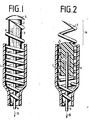
- the electrode lead In the heart-side end of a first embodiment of the electrode according to the invention shown in FIG. 1, the electrode lead consists of the part of a helical coil 2 covered with a jacket 1 made of flexible material, such as silicone rubber.
- This part (shown in the drawing in abbreviated form) has the part length required to connect the cardiac end of the electrode to the implanted pacemaker, the electrode lead preferably in a vein is laid.
- the jacket 1 leaves the corkscrew-like area 14 (FIG. 2) of the helix free which is screwed into the heart tissue in order to fasten the end.
- the area 14 to be screwed in in contrast to that described below, is shown in FIGS. 5 and 6 shown embodiment made in one piece with the part of the helix 2 forming the feed line.
- a protective core 3 Arranged within the helix is a protective core 3 forming the cylindrical body, which is mounted in the axial direction so as to be movable almost without play within the helix '2.
- the protective core 3 is rounded in a convex manner in its leading region in order to facilitate the insertion of the electrode.
- an actuating thread 4 is fastened, which is guided to the other end of the electrode feed line, so that the doctor fixing the electrode can exert a tensile force in the direction of arrow 15 on the protective core 3 from there in order to pull it back and out for fixation to remove the area 14 of the helix.
- the front area of the protective core 3 in the direction of insertion of the electrode has a larger diameter than the helix 2 at its front end and has an elastic, circumferential edge 5 which projects beyond the engagement area of the helix 2 'in the radial direction in such a way that it is designed as a tip End of the same can not come into engagement with the heart before the protective core 3 is withdrawn.
- the protective core 3 can also be removed using a rigid actuating element, such as a wire, by pushing it out in the opposite direction.
- the protective core 3 itself is also made of silicon rubber, and contains an X-ray-tight core (shown in dashed lines), which acts as one of the actuators supply thread 4 securing sleeve 6 is formed and vulcanized into the protective core 3.
- the radiopaque core Due to the radiopaque core, it is possible to check the position of the protective core 3 with respect to the coil 2 in the heart at any time by means of an X-ray device during the insertion process, so that the doctor can assess both the position of the electrode end and the position of the core in Terms of the spiral, ie whether the coil for screwing in the electrode end has completely released the front part of the coil. In order to effect this release, all that is required is a pull on the blocking thread 4 in the direction of the arrow 15, the jacket 1 enveloping the coil 2 having to be held in an area of the electrode lead which is outside the patient's body. The protective core 3 then reaches its position shown in FIG. 2. (In contrast to Fig. 1, the protective core is shown in section here.)
- the length of the protective core forming a cylindrical body is chosen so that a secure guidance of the same inside the helix is ensured in the longitudinal direction, which is achieved in that it extends over several screw turns.
- the existing friction between the protective core 3 and the helix 2 prevents uncontrolled relative movements of the helix, which are to be prevented in particular during the insertion process, since they could result in premature release of the screw-in area of the helix.
- a circumferential elastic edge 5 is designed so resilient that it when removed from the screwed-in area 14, the helix 2 is deformed by pulling on the actuating thread 4 such that it passes the turns of the helix. Essentially only the portion of the elastic edge 5 that just intersects the helix of the helix is deformed, as can be seen on the left in FIG. 2.
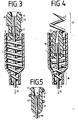
- a second embodiment of the invention is shown in two variants.
- the cylindrical body is tulip-shaped, so that the existing inner cavity results in a particularly good deformability of the areas engaging in the coil when the body is removed from the engagement area of the coil for screwing into the heart tissue.
- a sleeve 10 connected to the actuating thread 4 is provided in the inner cavity of the protective core 13 and is clamped on the actuating thread 4.
- the sleeve 10 is axially displaceable.
- the path of the sleeve 10 is limited by a stop ring 11 vulcanized into the protective core, which is also made of silicone rubber.
- the sleeve 10 and the protective core 13 are in the position shown in FIG. 3.
- the outer surface of the protective core 13 has a helical circumferential elevation 12 which is adapted to the helix 2 in its area 14 to be screwed in.
- the turns of the coil lie in the groove between adjacent flanks of the elevation 12, which occurs when the protective core 13 is pushed back when the electrode is inserted Tending forces at least to the extent that the sharp end of the coil 2 does not get beyond the surface of the protective core.
- the sleeve 10 is located in the region of the turns stored in the channel and prevents the wall of the hollow protective core 13 from yielding elastically inward, so that the relative position of the protective core and the spiral is maintained as long as the sleeve 10 occupies this position.
- the attending physician pulls on the actuating thread 4 in the direction of the arrow 15, whereupon the sleeve 10 clamped on the thread slides downward in the protective core 13 until it has reached the stop ring 11.
- the sleeve 10 in turn begins to drive the protective core 13 in the direction of the pulling direction of the actuating thread 4 via the stop ring 11. Since the sleeve is no longer in the area of the protective core, within which it resists the elastic deformation of the wall area, due to the fact that the engagement area 14 of the helix is supported in between adjacent flanks of the circumferential elevation 12, the protective core can be here Reduce cross-section and slide down between the coils.
- the actuating thread 4 can be pulled out at the other end of the electrode until the protective core reaches a subsequent narrowed area 16 of the helix, where a further movement in the direction of arrow 15 is opposed to resistance.
- the sleeve 10 is made of an X-ray opaque material, the doctor can in turn track the movement of the sleeve with respect to the coil using an X-ray device.
- FIG. 5 shows a variant of the protective core 13 'which is tulip-shaped.
- the circumferential edge projects in the radial direction in the area of the front plane of the engagement area in the radial direction and is elastically deformable. Silicone rubber is also used as the material. If a force is exerted on the actuating thread 4 in the direction of the arrow 15, the edge deforms in the direction of the interior of the protective core 13 'and thereby passes the helix 2.
- a radiopaque core 17 is arranged, which is crimped within the protective core 13' and secured against falling out by means of a plate 8 fastened by an adhesive point 9.
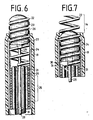
- FIG. 6 shows a further embodiment of the electrode according to the invention, FIG. 6 showing the preceding part of the electrode in the state ready for insertion into the vein.
- the electrode lead consists of a lead helix 18 which is encased by a silicone tube 19.
- An inner clamping sleeve 20 is inserted into the inside of the supply coil 18, while the outside of the supply coil 18 is surrounded by a central clamping sleeve 21 in this area.
- the actual screw-in helix 22 is in turn wound around the middle clamping sleeve 21.
- An outer clamping and guide sleeve 24 is arranged around this arrangement, the sleeves and coils mentioned being mechanically and electrically connected to one another by being squeezed in the region 25.
- the alloy "Elgiloy" serves as the material for the sleeves and coils.
- the screw-in helix 22 projects out of the silicone tube 19 with its engagement area 14.
- the protective core 23 is so far outside of the jacket 1 that its rounded front surface projects beyond the front plane of the screw-in helix 22.
- the protective core 23 has a thread-forming circumferential groove 26 with a helical pitch which is adapted to the pitch of the screw-in helix 22. (The diameter of the foremost helix is reduced in a spiral towards its end near the heart and is thus adapted to the rounding of the protective core.
- the core consists of essentially rigid material, such as polyurethane.
- a guide wire 28 is used as a tool for transmitting the torque, which has a flattened end 29.
- This guide wire also serves to stiffen the If the electrode has reached its position intended for the fixation, the doctor can carry out threshold measurements with the protective core still taking up its position for the insertion process before the electrode is finally fixed, since outer parts of the screw-in helix 22 already come into contact with the tissue in their engagement region 14. If these measurements are not yet satisfactory, the electrode end can be pushed forward or pulled back as desired.
- the protective core 23 is screwed back into the interior of the silicone tube 19 by means of the flattened end 29 engaging in the recess 27 of the guide wire 28 rotated about its axis, so that the engagement area 14 of the screw-in helix 22 is inserted allows unimpeded screwing of the electrode end into the tissue.
- Fig. 7 the protective core 23 is shown during the screwing back. It can be screwed towards the inside of the silicone tube 19 until its rear surface 30 comes into contact with the edge 31 of the middle clamping sleeve 21. This results in a saw limit by a stop, so that the doctor can see that the protective core 23 has reached its end position. At the same time, the surface 21 lies on the edge 30, which slightly projects beyond the corresponding edge of the inner clamping sleeve 20, so that the interior of the electrode lead is protected against penetrating body fluids. To screw in the electrode, the electrode lead is turned by the doctor in the area of the end located outside the patient's body. Then the guide wire 28 is pulled back.
Applications Claiming Priority (2)
| Application Number | Priority Date | Filing Date | Title |
|---|---|---|---|
| DE19772736737 DE2736737A1 (de) | 1977-08-16 | 1977-08-16 | Implantierbare elektrode |
| DE2736737 | 1977-08-16 |
Publications (1)
| Publication Number | Publication Date |
|---|---|
| EP0000725A1 true EP0000725A1 (fr) | 1979-02-21 |
Family
ID=6016427
Family Applications (1)
| Application Number | Title | Priority Date | Filing Date |
|---|---|---|---|
| EP7878100491A Withdrawn EP0000725A1 (fr) | 1977-08-16 | 1978-07-24 | Electrode cardiaque implantable |
Country Status (4)
| Country | Link |
|---|---|
| EP (1) | EP0000725A1 (fr) |
| BR (1) | BR7805235A (fr) |
| DE (1) | DE2736737A1 (fr) |
| IT (1) | IT1097326B (fr) |
Cited By (4)
| Publication number | Priority date | Publication date | Assignee | Title |
|---|---|---|---|---|
| EP0004785A1 (fr) * | 1978-04-10 | 1979-10-17 | Edward David Hon | Appareil de surveillance fétale |
| EP0015229A1 (fr) * | 1979-02-21 | 1980-09-03 | BIOTRONIK Mess- und Therapiegeräte GmbH & Co Ingenieurbüro Berlin | Electrode pour stimulateur cardiaque artificiel |
| EP0489965A1 (fr) * | 1990-12-14 | 1992-06-17 | Peter Dr. Ing. Osypka | Conduit de stimulateur cardiaque muni d'une hélice |
| WO2005089196A2 (fr) * | 2004-03-15 | 2005-09-29 | Rovcal, Inc. (California Corporation) | Structure de systeme de coupe amelioree pour rasoirs electriques a sec avec grille |
Citations (3)
| Publication number | Priority date | Publication date | Assignee | Title |
|---|---|---|---|---|
| FR2302107A1 (fr) * | 1973-06-21 | 1976-09-24 | Medtronic Inc | Electrode intracardiaque |
| DE2533766A1 (de) * | 1975-07-29 | 1977-02-03 | Bisping Hans Juergen | Transvenoese, implantierbare herzschrittmacherelektrode |
| FR2322582A1 (fr) * | 1975-09-05 | 1977-04-01 | Osypka Peter | Dispositif d'electrode pour utilisation dans le domaine medical |
-
1977
- 1977-08-16 DE DE19772736737 patent/DE2736737A1/de not_active Withdrawn
-
1978
- 1978-07-24 EP EP7878100491A patent/EP0000725A1/fr not_active Withdrawn
- 1978-07-25 IT IT26085/78A patent/IT1097326B/it active
- 1978-08-15 BR BR7805235A patent/BR7805235A/pt unknown
Patent Citations (3)
| Publication number | Priority date | Publication date | Assignee | Title |
|---|---|---|---|---|
| FR2302107A1 (fr) * | 1973-06-21 | 1976-09-24 | Medtronic Inc | Electrode intracardiaque |
| DE2533766A1 (de) * | 1975-07-29 | 1977-02-03 | Bisping Hans Juergen | Transvenoese, implantierbare herzschrittmacherelektrode |
| FR2322582A1 (fr) * | 1975-09-05 | 1977-04-01 | Osypka Peter | Dispositif d'electrode pour utilisation dans le domaine medical |
Cited By (5)
| Publication number | Priority date | Publication date | Assignee | Title |
|---|---|---|---|---|
| EP0004785A1 (fr) * | 1978-04-10 | 1979-10-17 | Edward David Hon | Appareil de surveillance fétale |
| EP0015229A1 (fr) * | 1979-02-21 | 1980-09-03 | BIOTRONIK Mess- und Therapiegeräte GmbH & Co Ingenieurbüro Berlin | Electrode pour stimulateur cardiaque artificiel |
| EP0489965A1 (fr) * | 1990-12-14 | 1992-06-17 | Peter Dr. Ing. Osypka | Conduit de stimulateur cardiaque muni d'une hélice |
| WO2005089196A2 (fr) * | 2004-03-15 | 2005-09-29 | Rovcal, Inc. (California Corporation) | Structure de systeme de coupe amelioree pour rasoirs electriques a sec avec grille |
| WO2005089196A3 (fr) * | 2004-03-15 | 2007-07-05 | Rovcal Inc California Corp | Structure de systeme de coupe amelioree pour rasoirs electriques a sec avec grille |
Also Published As
| Publication number | Publication date |
|---|---|
| IT1097326B (it) | 1985-08-31 |
| IT7826085A0 (it) | 1978-07-25 |
| DE2736737A1 (de) | 1979-03-01 |
| BR7805235A (pt) | 1979-04-17 |
Similar Documents
| Publication | Publication Date | Title |
|---|---|---|
| EP0009619B1 (fr) | Electrode pour stimulateur cardiaque pour application transveineuse | |
| EP0348692B1 (fr) | Dispositif pour l'introduction transveneuse ou artérielle a moyen d'un fil guide | |
| DE2560406C2 (de) | Implantierbare Zuleitung mit verankerbarer Elektrode | |
| DE60109599T2 (de) | Vorrichtung zum einführen von elektrischen, medizinischen leitungen | |
| EP2296561B1 (fr) | Bouchon pour endoscope | |
| DE2755179A1 (de) | Vorrichtung zum ansetzen eines messkopfes | |
| EP0003948A1 (fr) | Electrode implantable | |
| EP1759632A1 (fr) | Dispositif implantable pour la mesure des paramètres biométriques du sang | |
| DE102009051408A1 (de) | Medizinisches Instrument zum Setzen von Gewebeklammern | |
| DE2719287A1 (de) | Implantable leitung mit versteifungsmandrin | |
| DE102009050829A1 (de) | Resektionsvorrichtung | |
| EP1334745B1 (fr) | Fil de guidage et conducteur implantable | |
| EP3320946A1 (fr) | Conduite implantable | |
| EP0385116B1 (fr) | Conducteur d'électrode de stimulateur cardiaque | |
| EP0489965B1 (fr) | Conduit de stimulateur cardiaque muni d'une hélice | |
| DE3536823A1 (de) | Elektrische elektrode und ein verfahren zum anbringen der elektrode an knochengewebe | |
| DE2848483B2 (de) | Gerät zur Gewebeentnahme | |
| EP0000725A1 (fr) | Electrode cardiaque implantable | |
| EP0015229B1 (fr) | Electrode pour stimulateur cardiaque artificiel | |
| DE2453840B2 (de) | Herzschrittmacherelektrode | |
| EP1062972B1 (fr) | Ensemble électrode | |
| DE2806069A1 (de) | Endocardiale stimulationselektrode | |
| DE3027383A1 (de) | Transvenoese herzschrittmacherelektrode | |
| DE2931643A1 (de) | Herzschrittmacherelektrode | |
| DE102016105845A1 (de) | Elektrodenkopf für eine Herzschrittmacher- oder Defibrillator-Elektrode |
Legal Events
| Date | Code | Title | Description |
|---|---|---|---|
| PUAI | Public reference made under article 153(3) epc to a published international application that has entered the european phase |
Free format text: ORIGINAL CODE: 0009012 |
|
| AK | Designated contracting states |
Designated state(s): BE CH DE FR GB LU NL SE |
|
| 17P | Request for examination filed | ||
| STAA | Information on the status of an ep patent application or granted ep patent |
Free format text: STATUS: THE APPLICATION IS DEEMED TO BE WITHDRAWN |
|
| 18D | Application deemed to be withdrawn |
Effective date: 19820522 |