EP0000725A1 - Implantible cardiac electrode - Google Patents
Implantible cardiac electrode Download PDFInfo
- Publication number
- EP0000725A1 EP0000725A1 EP7878100491A EP78100491A EP0000725A1 EP 0000725 A1 EP0000725 A1 EP 0000725A1 EP 7878100491 A EP7878100491 A EP 7878100491A EP 78100491 A EP78100491 A EP 78100491A EP 0000725 A1 EP0000725 A1 EP 0000725A1
- Authority
- EP
- European Patent Office
- Prior art keywords
- electrode
- cylindrical body
- electrode according
- coil
- helical
- Prior art date
- Legal status (The legal status is an assumption and is not a legal conclusion. Google has not performed a legal analysis and makes no representation as to the accuracy of the status listed.)
- Withdrawn
Links
Images
Classifications
-
- A—HUMAN NECESSITIES
- A61—MEDICAL OR VETERINARY SCIENCE; HYGIENE
- A61N—ELECTROTHERAPY; MAGNETOTHERAPY; RADIATION THERAPY; ULTRASOUND THERAPY
- A61N1/00—Electrotherapy; Circuits therefor
- A61N1/02—Details
- A61N1/04—Electrodes
- A61N1/05—Electrodes for implantation or insertion into the body, e.g. heart electrode
- A61N1/056—Transvascular endocardial electrode systems
- A61N1/057—Anchoring means; Means for fixing the head inside the heart
- A61N1/0573—Anchoring means; Means for fixing the head inside the heart chacterised by means penetrating the heart tissue, e.g. helix needle or hook
Landscapes
- Health & Medical Sciences (AREA)
- Cardiology (AREA)
- Heart & Thoracic Surgery (AREA)
- Vascular Medicine (AREA)
- Engineering & Computer Science (AREA)
- Biomedical Technology (AREA)
- Nuclear Medicine, Radiotherapy & Molecular Imaging (AREA)
- Radiology & Medical Imaging (AREA)
- Life Sciences & Earth Sciences (AREA)
- Animal Behavior & Ethology (AREA)
- General Health & Medical Sciences (AREA)
- Public Health (AREA)
- Veterinary Medicine (AREA)
- Electrotherapy Devices (AREA)
Abstract
Description
Die Erfindung betrifft eine Elektrode zur Implantation im Herzen, insbesondere zur Stimulation des Herzmuskels, mit einer Elektrodenzuleitung, einer schraubenförmigen, vorstehenden Wendel am herznahen Ende der Elektrodenzuleitung zum Einschrauben der Elektrode ins Herzgewebe und einer die Front der Wendel während der Einführungsphase überragenden Schutzvorrichtung gegen ungewolltes Verhaken.The invention relates to an electrode for implantation in the heart, in particular for stimulating the heart muscle, with an electrode lead, a helical, protruding coil at the end of the electrode lead close to the heart for screwing the electrode into the heart tissue and a protective device against unwanted hooking which protrudes the front of the coil during the insertion phase .
Derartige Elektroden dienen zur Übertragung von Stimulationsimpulsen und physiologischen Signalen zwischen dem Herzmuskel und einem ebenfalls implantierten künstlichen Herzschrittmacher.Such electrodes are used to transmit stimulation pulses and physiological signals between the heart muscle and an artificial pacemaker, which is also implanted.
Dabei ist es aus der DE-OS 26 13 044 bekannt, die schraubenförmige Wendel durch eine diese seitlich umfassende elastische Manschette zu schützen. Wenn das herznahe Elektrodenende bei der Implantation an einer geeigneten Stelle innerhalb des Herzens plaziert ist, wird durch Ausübung einer Kraft in Einführungsrichtung über die Elektrodenzuleitung und ein gleichzeitiges Drehen derselben die Wendel in das Herzgewebe eingeschraubt, während der vordere Rand der Manschette im Bereich des die Einstichstelle umgebenden Gewebes aufliegt und sich mit dem Einschrauben der Wendel zunehmend zusammenstaucht, wodurch der einzuschraubende Teil der Wendel freigegeben wird. Hierzu muß die Elektrodenzuleitung jedoch verhältnismäßig steif ausgebildet sei, so daß nicht nur der zum Einschrauben der Wendel erforderliche, sondern zusätzlich auch der zum Stauchen der Manschette notwendige Druck über die Elektrodenzuleitung übertragen werden kann. Aus Gründen der Bruchsicherheit sollten derartige Elektrodenzuleitungen aber möglichst weich sein. Weiterhin ist nachteilig, daß die Manschette nach erfolgter Fixierung der Elektrode im Herzgewebe ständig eine Kraft ausübt, die so gerichtet ist, daß der eingeschraubte Teil des Elektrodenendes herausgezogen wird. Außerdem wird die Bildung von fibrinösem Gewebe gefördert, so daß insgesamt die Tendenz besteht, die Elektrode vorzeitig ineffektiv zu machen. Die Manschette muß dabei eine gewisse Mindeststeifigkeit aufwei-. sen, da sie, wäre sie weicher ausgebildet, zwar im befestigten Zustand eine geringere Kraft ausüben würde, in diesem Fall aber die Gefahr bestünde, daß die Manschette die schraubenförmige Wendel schon während des Einführungsvorgangs freigibt, so daß sich diese. in der Vene verhakt oder daß sich die Manschette beim Einschrauben der Wendel derart mit deren Gewindegängen oder Spitze verwickelt bzw. verhakt, daß dadurch ein weiteres Einschrauben infolge Blockierung nicht mehr möglich ist.It is known from DE-OS 26 13 044 to protect the helical coil by means of an elastic cuff which laterally encompasses it. If the electrode end near the heart is placed at a suitable location within the heart during the implantation, the helix is screwed into the heart tissue by exerting a force in the direction of insertion via the electrode lead and simultaneously rotating the same, while the front edge of the cuff is in the area of the puncture site surrounding tissue rests and increasingly screwed together with the screwing of the helix, whereby the one screwing part of the helix is released. For this purpose, however, the electrode feed line must be designed to be relatively stiff, so that not only the pressure required for screwing in the helix, but also the pressure required for upsetting the sleeve can be transmitted via the electrode feed line. For reasons of break resistance, such electrode leads should be as soft as possible. Another disadvantage is that after the electrode has been fixed in the heart tissue, the cuff continuously exerts a force which is directed in such a way that the screwed-in part of the electrode end is pulled out. In addition, the formation of fibrinous tissue is promoted, so that overall there is a tendency to prematurely render the electrode ineffective. The cuff must have a certain minimum stiffness. sen, since they, if they were softer, would exert less force when fastened, but in this case there was a risk that the cuff would release the helical coil during the insertion process, so that it would become loose. hooked in the vein or that the cuff becomes entangled or hooked with the threads or tip when screwing the helix in such a way that further screwing in due to blocking is no longer possible.
Ein weiterer Nachteil der genannten Elektrode besteht darin, daß sie,bis zum Zeitpunkt der Fixierung von der Manschette umgeben ist, so daß vor dem Einschrauben ein elektrischer,Kontakt mit dem Herzgewebe für Reizschwellenmessungen bzw. die Registrierung des intrakardialen Elektrokardiogramms nicht möglich ist.Another disadvantage of the above-mentioned electrode is that it is surrounded by the cuff until the point of fixation, so that electrical contact with the heart tissue for measurement of the threshold or recording of the intracardiac electrocardiogram is not possible before screwing in.
Die Erfindung liegt die Aufgabe zugrunde, unter Vermeidung dieser Nachteile eine Elektrode der angegebenen Gattung so zu verbessern, daß sowohl ein gefahrloses Einführen als auch ein sicheres Befestigen im Herzgewebe gewährleistet ist. Vor der endgültigen Fixierung der Elektrode sollen elektrophysiologische Messungen vorgenommen werden können.The invention has for its object to avoid these disadvantages to improve an electrode of the type specified so that both a safe insertion and a secure attachment in the heart tissue is guaranteed. Before the final fixation of the electrode, electrophysiological measurements should be possible.
Diese Aufgabe wird erfindungsgemäß dadurch gelöst, daß innerhalb der schraubenförmigen Wendel ein zylindrischer Körper relativ zu dieser-in axialer Richtung derart bewegbar ist, daß er während der Einführungsphase der Elektrode mit der Front der schraubenförmigen Wendel abschließt oder diese überragt und zum Befestigen der schraubenförmigen Wendel im Herzgewebe aus deren in das Gewebe einzuschraubenden Bereich mittels eines von außerhalb des Körpers des Patienten betätigbaren Elements entfernbar ist.This object is achieved in that within the helical coil, a cylindrical body is movable relative to this - in the axial direction such that it closes with or protrudes from the front of the helical coil during the insertion phase of the electrode and for fixing the helical coil in Heart tissue can be removed from the area to be screwed into the tissue by means of an element which can be actuated from outside the patient's body.
Der Erfindung liegt die Erkenntnis zugrunde, daß ein im wesentlichen zylindrischer Körper innerhalb des herausragenden Teils der Wendel der Elektrode derart gelagert werden kann, daß er durch eine einfache Bewegung, wie eine Zug-, Schub- oder Drehbewegung aus dem Eingriffsbereich der Wendel entfernbar ist. Eine derartige Bewegung kann durch ein innerhalb oder außerhalb der Elektrode geführtes unkompliziertes Betätigungselement aufgebracht werden. Die .Beseitigung des als Schutzkern ausgebildeten zylindrischen Körpers, der einen sich an der Wendel abstützenden Kolben bildet, erfolgt durch eine relativ zwischen Betätigungselement und Elektrode aufgebrachte Kraft ohne Krafteinwirkung zwischen Elektrode und der den Einschraubbereich umgebenden Gewebeoberfläche.The invention is based on the finding that an essentially cylindrical body can be mounted within the projecting part of the coil of the electrode in such a way that it can be removed from the engagement area of the coil by a simple movement, such as a pulling, pushing or rotating movement. Such a movement can be applied by an uncomplicated actuating element guided inside or outside the electrode. Removal of the cylindrical body designed as a protective core, which forms a piston supported on the helix, is carried out by a force applied relatively between the actuating element and the electrode, without any action of force between the electrode and the tissue surface surrounding the screw-in area.
Es ist in vorteilhafter Weise möglich, ohne Befestigung der schraubenförmige Wendel im Gewebe bereits Reizschwellenmessungen vorzunehmen, da die Schraubenwendel nach außen freiliegt und einen elektrischen Kontakt zur Gewebeoberfläche ermöglicht.It is advantageously possible to carry out stimulus threshold measurements without fastening the helical coil in the tissue, since the screw coil is exposed to the outside and enables electrical contact to the tissue surface.
Der Antrieb des Körpers erfolgt ausschließlich über das Betätigungsmittel, und zwar durch Zug, Druck oder Drehung desselben. Für die Elektrodenzuleitung kann ein für derartige Elektrodenzuleitungen bevorzugter weicher Werkstoff Verwendung finden, da nicht zusätzlich zum Druck beim Einschrauben der Elektrode in das Herzgewebe noch eine Kraft zum Beseitigen der Schutzvorrichtung aufgebracht werden muß.The body is driven exclusively by the actuating means, namely by pulling, pushing or rotating the same. A preferred soft material for such electrode leads can be used for the electrode lead, since it is not necessary to apply a force to remove the protective device in addition to the pressure when the electrode is screwed into the heart tissue.
Dabei ist der Schutzkern vorteilhafterweise an einem entlang der Elektrodenleitung geführten Betätigungsfaden oder -draht' befestigt. Damit wird der zylindrische Körper entsprechend in axialer Richtung angetrieben, so daß er während der Einführungsphase den einzuschraubenden Teil der schraubenförmige Wendel wirkungslos macht und vor Einschrauben der Wendel im Herzgewebe zurückgezogen werden kann.The protective core is advantageously fastened to an actuating thread or wire which is guided along the electrode line. So that the cylindrical body is driven accordingly in the axial direction, so that it makes the screw-in part of the helical coil ineffective during the insertion phase and can be withdrawn before screwing the coil into the heart tissue.
In weiterer vorteilhafter Ausgestaltung ist der zylindrische Körper mindestens teilweise aus einem für Röntgenstrahlung undurchlässigem Material wie Platin hergestellt, so daß es dem implantierenden.Arzt über ein Röntgengerät möglich ist, die Lage des zylindrischen Körpers in Bezug auf die Wendel jederzeit zu kontrollieren und sich damit davon zu überzeugen, daß der Eingriffsbereich der Wendel zum Einschrauben freigegeben ist.In a further advantageous embodiment, the cylindrical body is at least partially made of a material that is opaque to X-radiation, such as platinum, so that the implanting doctor can use an X-ray device to check the position of the cylindrical body with respect to the coil at any time and thus to get away from it to convince that the engagement area of the helix is released for screwing.
Eine Erhöhung des Schutzes der schraubenförmige Wendel wird erreicht, wenn der zylindrische Körper an seinem vorderen Ende einen umlaufenden elastischen, gegebenenfalls als eine Art Lippe ausgebildeten Rand aufweist, der den zylindrischen Körper, d.h. den Eingriffsbereich der schraubenförmigen Wendel in radialer Richtung überragt.An increase in the protection of the helical helix is achieved if the cylindrical body has at its front end a circumferential elastic edge, optionally designed as a kind of lip, which surrounds the cylindrical body, i.e. projects beyond the engagement area of the helical coil in the radial direction.
Gemäß einer modifizierten Ausführung kann der zylindrische Körper tulpenförmig in seinem Inneren hohl ausgebildet sein, wodurch sich besonders günstige Möglichkeiten für den Aufbau ergeben.According to a modified embodiment, the cylindrical body can be hollow in the shape of a tulip, which results in particularly favorable construction options.
Da die Wirksamkeit des zylindrischen Körpers von seiner Führung innerhalb der schraubenförmige Wendel abhängt, ist der Körper innerhalb vorzugsweise der Wendel im wesentlichen spielfrei gelagert bzw. weist gewindeähnliche Gänge auf, die im Zusammenwirken mit der schraubenförmigen Steigung der Wendel einen Schraubvorgang ermöglichen. Als "Schraubenzieher" kann dabei ein entsprechend ausgebildeter Führungsdraht dienen, der zum Versteifen der Elektrode beim Einführen ohnehin erforderlich ist. Da der Körper sich in Längsrichtung zweckmäßigerweise über mehrere Windungen der Wendel erstreckt, ergibt sich eine besonders stabile Führung für die Relativbewegung zwischen der Wendel und dem Körper.Since the effectiveness of the cylindrical body depends on its guidance within the helical helix, the body within the helix is preferably mounted essentially free of play or has thread-like gears which, in cooperation with the helical pitch of the helix, enable a screwing process. An appropriately trained guidewire can be used as a "screwdriver", which is required anyway to stiffen the electrode during insertion. Since the body expediently extends in the longitudinal direction over several turns of the helix, this results in a particularly stable guidance for the relative movement between the helix and the body.
.Der Einführungsvorgang wird erleichtert, wenn der zylindrische Körper in seinem beim-Einführen der Elektrode vorangeführten Bereich konvex verrundet ist.The insertion process is facilitated if the cylindrical body is convexly rounded in its area leading up to the insertion of the electrode.
Weitere vorteilhafte Ausführungsformen der Erfindung sind in den Unteransprüchen angegeben und werden im Folgenden anhand der Zeichnungen näher beschrieben. Es zeigen (jeweils vergrößert und im Schnitt dargestellt):
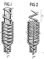
- Fig.1 das mit dem Herzgewebe in Eingriff kommende Ende einer ersten Ausführungsform der erfindungsgemäßen Elektrode, wobei sich der zylindrische Körper in der die Wendel schützende Stellung befindet,
- Fig. 2 die Ausführungsform gemäß Fig. 1, wobei sich der zylindrische Körper in zurückgezogener, die Wendel zum Einschrauben freigegebenen Stellung befindet,
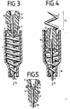
- Fig. 3 eine. weitere Ausführungsform der erfindungsgemäßen Elektrode in der Darstellung entsprechend Fig. 1,
- Fig. 4 die Ausführungsform der Elektrode gemäß Fig. 3 in der Fig. 2 entsprechenden Darstellung,
- Fig. 5 eine Variante des zylindrischen Körpers für die Ausführungsform entsprechend den Fign. 3.und 4,
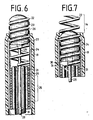
- Fig. 6 eine dritte Ausführungsform der Erfindung, in der Fig. 1 entsprechenden Darstellung und
- Fig. 7 die in Fig. 6 wiedergegebene Ausführungsform in der Fig. 2 entsprechenden Darstellung.
- 1 shows the end of a first embodiment of the electrode according to the invention which engages with the heart tissue, the cylindrical body being in the position protecting the helix,
- 2 shows the embodiment according to FIG. 1, the cylindrical body being in the retracted position, the coil being released for screwing in,
- Fig. 3 a. another embodiment of the electrode according to the invention in the representation corresponding to FIG. 1,
- 4 shows the embodiment of the electrode according to FIG. 3 in the representation corresponding to FIG. 2,
- 5 shows a variant of the cylindrical body for the embodiment corresponding to FIGS. 3rd and 4th,
- Fig. 6 shows a third embodiment of the invention, in the Fig. 1 corresponding representation and
- FIG. 7 shows the embodiment shown in FIG. 6 in the representation corresponding to FIG. 2.
Bei dem in Fig. 1 dargestellten herzseitigen Ende einer ersten Ausführungsform der erfindungsgemäßen Elektrode besteht die Elektrodenzuleitung aus dem mit einem Mantel 1 aus flexiblem Material, wie beispielsweise Silikonkautschuk, überzogenen Teil einer schraubenförmigen Wendel 2. Dieser (in der Zeichnung gekürzt dargestellte) Teil weist die zur Verbindung des herzseitigen Endes der Elektrode mit dem implantierten Herzschrittmacher erforderliche Länge auf, wobei die Elektrodenzuleitung vorzugsweise in einer Vene verlegt wird. Der Mantel 1 läßt denjenigen korkenzieherartigen Bereich 14 (Fig. 2) der Wendel frei, der zum Befestigen des Endes in das Herzgewebe eingeschraubt wird. Der einzuschraubende Bereich 14 ist bei der hier dargestellten Ausführungsform, im Gegensatz zu der weiter unten beschriebenen, in den Fign. 5 und 6 dargestellten Ausführung einstückig mit dem die Zuleitung bildenden Teil der Wendel 2 ausgeführt.In the heart-side end of a first embodiment of the electrode according to the invention shown in FIG. 1, the electrode lead consists of the part of a
Innerhalb der Wendel ist ein den zylindrischen Körper bildender Schutzkern 3 angeordnet, der nahezu spielfrei innerhalb der Wendel '2 in axialer Richtung beweglich gelagert ist. Der Schutzkern 3 ist zum Erleichtern des Einführens der Elektrode in seinem dabei vorangeführten Bereich konvex verrundet. Am Schutzkern 3 ist ein Betätigungsfaden 4 befestigt, der bis zum anderen Ende der Elektrodenzuleitung geführt ist, so daß der die Elektrode fixierende Arzt von dort aus eine Zugkraft in Richtung des Pfeils 15 auf den Schutzkern 3 ausüben kann, um ihn zurückzuziehen und zur Fixierung aus dem Bereich 14 der Wendel zu entfernen. Der in Einführungsrichtung der Elektrode vordere Bereich des Schutzkerns 3 hat einen größeren Durchmesser als die Wendel 2 an ihrem vorderen Ende und weist einen elastischen, umlaufenden Rand 5 auf, welcher den Eingriffsbereich der Wendel 2'in radialer Richtung so überragt, daß das als Spitze ausgebildete Ende derselben nicht mit dem Herzen in Eingriff kommen kann, bevor der Schutzkern 3 zurückgezogen ist. (Das Beseitigen des Schutzkerns 3 kann auch über ein starres Betätigungselement wie einen Draht durch Hinausschieben in entgegengesetzter Richtung erfolgen.) Der Schutzkern 3 selbst ist ebenfalls aus Sili-, konkautschuk hergestellt und enthält einen röntgendichten Kern (gestrichelt dargestellt), der als eine den Betätigungsfaden 4 sichernde Klemmhülse 6 ausgebildet und in den Schutzkern 3 einvulkanisiert ist.Arranged within the helix is a protective core 3 forming the cylindrical body, which is mounted in the axial direction so as to be movable almost without play within the helix '2. The protective core 3 is rounded in a convex manner in its leading region in order to facilitate the insertion of the electrode. On the protective core 3, an actuating thread 4 is fastened, which is guided to the other end of the electrode feed line, so that the doctor fixing the electrode can exert a tensile force in the direction of
Durch den röntgendichten Kern ist es möglich, jederzeit mittels eines Röntgengerätes während des-Einführungsvorgangs die Lage des Schutzkerns 3 in Bezug auf die Wendel 2 im Herzen zu kontrollieren, so daß der Arzt sowohl die Lage des Elektrodenendes beurteilen kann als auch die Position des Kerns in Bezug auf die Wendel, d.h. ob die Wendel zum Einschrauben des Elektrodenendes den vorderen Teil der Wendel vollständig freigegeben hat. Um diese Freigabe zu bewirken, ist lediglich ein Zug an dem Sperrfaden 4 in Richtung des Pfeils 15 erforderlich, wobei der die Wendel 2 umhüllende Mantel 1 in einem außerhalb des Körpers des Patienten befindlichen Bereich der Elektrodenzuleitung festgehalten werden muß. Der Schutzkern 3 gelangt daraufhin in seine in Fig. 2 dargestellte Position. (Der Schutzkern ist hier im Gegensatz zu Fig. 1 geschnitten wiedergegeben. )Due to the radiopaque core, it is possible to check the position of the protective core 3 with respect to the
Die Länge des einen zylindrischen Körper bildenden Schutzkerns ist dabei so gewählt, daß eine sichere Führung desselben innerhalb der Wendel in Längsrichtung gewährleistet ist, was dadurch erreicht wird, daß er sich über mehrere Schraubengänge erstreckt. Durch die vorhandene Reibung zwischen dem Schutzkern 3 und der Wendel 2 werden unkontrollierte Relativbewegungen derselben unterbunden, die insbesondere während des Einführungsvorgangs zu verhindern sind, da sie eine vorzeitige Freigabe des Einschraubbereichs der' Wendel zur Folge haben könnten.The length of the protective core forming a cylindrical body is chosen so that a secure guidance of the same inside the helix is ensured in the longitudinal direction, which is achieved in that it extends over several screw turns. The existing friction between the protective core 3 and the
Wie sich aus Fig. 2 ergibt, ist ein umlaufender elastischer Rand 5 derart nachgiebig ausgebildet, daß er sich beim Entfernen aus dem einzuschraubenen Bereich 14 der Wendel 2 durch Zug an dem Betätigungsfaden 4 derart verformt, daß er an den Windungen der Wendel vorbeigelangt. Dabei wird im wesentlichen nur jeweils der gerade die Schraubenlinie der Wendel schneidende Teilbereich des elastischen Rands 5 verformt, wie es in Fig. 2 links ersichtlich ist.As is apparent from Fig. 2, a circumferential
In den Fign. 3, 4 und 5 ist eine zweite Ausführungsform der Erfindung in zwei Varianten dargestellt. Dabei ist der zylindrische Körper tulpenförmig ausgebildet, so daß sich durch den vorhandenen Innenhohlraum eine besonders gute Verformbarkeit der in die Wendel eingreifende Bereiche beim Entfernen des Körpers aus dem Eingriffsbereich der Wendel zum Einschrauben in das Herzgewebe ergibt. Bei der in den Fign. 3 und 4 dargestellten ersten Variante der zweiten Ausführungsform ist im inneren Hohlraum des Schutzkerns 13 eine mit dem Betätigungsfaden 4 verbundene Hülse 10 vorgesehen, die auf dem Betätigungsfaden 4 festgeklemmt ist. In der inneren Öffnung des tulpenförmig geformten Schutzkerns 13 ist die Hülse 10 in axialer verschiebbar angeordnet. In Betätigungsrichtung des Fadens 4 wird der Weg der Hülse 10 jedoch durch einen in den ebenfalls aus Silikonkautschuk bestehenden Schutzkern einvulkanisierten Anschlagring 11 begrenzt. Zum Einführen der Elektrode befinden sich die Hülse 10 und der Schutzkern 13 in der in Fig. 3 dargestellten Position. Die Außenoberfläche des Schutzkerns 13 weist eine schraubenförmig umlaufende Erhebung 12, die an die Wendel 2 in ihrem einzuschraubenden Bereich 14 angepaßt ist. Die Windungen der Wendel liegen dabei in der Rinne zwischen benachbarten Flanken der Erhebung 12, welche ein Zurückschieben des Schutzkerns 13 durch beim Einführen der Elektrode auftretende Kräfte mindestens insoweit verhindert, daß das scharfe Ende der Wendel 2 nicht über die vorangeführte Fläche des Schutzkerns hinausgelangt. Die Hülse 10 befindet sich im Bereich der in der Rinne gelagerten Windungen und verhindert ein elastisches Nachgeben der Wandung des hohlen Schutzkerns 13 nach innen, so daß die relative Lage von Schutzkern und Wendel aufrechterhalten bleibt, solange die Hülse 10 diese Position einnimmt.In Figs. 3, 4 and 5, a second embodiment of the invention is shown in two variants. The cylindrical body is tulip-shaped, so that the existing inner cavity results in a particularly good deformability of the areas engaging in the coil when the body is removed from the engagement area of the coil for screwing into the heart tissue. In the case of the figures 3 and 4 shown first variant of the second embodiment, a
Um den Eingriffsbereich 14 in das Herzgewebe einzuschrauben, zieht der behandelnde Arzt an dem Betätigungsfaden 4 in Richtung des Pfeils 15, woraufhin die auf dem Faden festgeklemmte Hülse 10 in dem Schutzkern 13 abwärts gleitet bis sie den Anschlagring 11 erreicht hat. Damit beginnt die Hülse 10 ihrerseits über den Anschlagring 11 den Schutzkern 13 in Richtung der Zugrichtung des Betätigungsfadens 4 anzutreiben. Da die Hülse sich nicht mehr in dem Bereich des Schutzkerns befindet, innerhalb dessen sie der elastischen Verformung des Wandbereichs, dadurch, daß der Eingriffsbereich 14 der Wendel in zwischen benachbarten Flanken der umlaufenden Erhebung 12 gelagert ist, einen Widerstand entgegensetzt, kann der Schutzkern hier seinen Querschnitt verringern und zwischen den Wendeln abwärts gleiten. Er nimmt dabei ein Profil ein, wie es in Fig. 4 dargestellt ist. Der Betätigungsfaden 4 kann dabei am anderen Ende der Elektrode soweit herausgezogen werden, bis der Schutzkern in einen anschließenden verengten Bereich 16 der Wendel gelangt, wo einer weiteren Bewegung in Richtung des Pfeils 15 ein Widerstand entgegengesetzt ist. Wenn die Hülse 10 aus einem für Röntgenstrahlen undurchlässigen Material gefertigt ist, kann der Arzt wiederum die Bewegung der Hülse in Bezug auf die Wendel mittels eines Röntgengerätes verfolgen.In order to screw the
In Fig. 5 ist eine Variante des Schutzkerns 13' dargestellt, der tulpenförmig ausgebildet ist. Der umlaufende Rand überragt die Wendel im Bereich der Frontebene des Eingriffsbereichs in radialer Richtung und ist elastisch deformierbar. Als Material wird ebenfalls Silikonkautschuk verwendet. Wenn auf den Betätigungsfaden 4 in Richtung des Pfeils 15 eine Kraft ausgeübt wird, deformiert sich der Rand in Richtung auf das Innere des Schutzkern 13' und gelangt dabei an der Wendel 2 vorbei. Innerhalb des Schutzkerns. 13' ist wiederum ein röntgendichter Kern 17 angeordnet, der quetschend innerhalb des Schutzkerns 13' befestigt und mittels eines durch eine Klebstelle 9 befestigten Plättchens 8 gegen Herausfallen gesichert ist.5 shows a variant of the protective core 13 'which is tulip-shaped. The circumferential edge projects in the radial direction in the area of the front plane of the engagement area in the radial direction and is elastically deformable. Silicone rubber is also used as the material. If a force is exerted on the actuating thread 4 in the direction of the
In den Fign. 6 und 7 ist eine weitere Ausführungsform der erfindungsgemäßen Elektrode dargestellt, wobei Fig. 6 den vorangeführten Teil der Elektrode im zum Einführen in die Vene bereiten Zustand zeigt. Die Elektrodenzuleitung besteht bei dieser Ausführungsform aus einer Zuleitungswendel 18, die von einem Silikonschlauch 19 ummantelt ist. In das Innere der Zuleitungswendel 18 ist eine innere Klemmhülse 20 eingefügt, während das Äußere der Zuleitungswendel 18 in diesem Bereich von einer mittleren Klemmhülse 21 umgeben ist. Um die mittlere Klemmhülse 21 ist wiederum die eigentliche Einschraubwendel 22 gewunden. Um diese Anordnung herum ist eine äußere Klemm- und Führungshülse 24 angeordnet, wobei die genannten Hülsen und Wendeln durch Quetschen im Bereich 25- mechanisch und elektrisch miteinander verbunden sind. Als Werkstoff für die Hülsen und Wendeln dient die Legierung "Elgiloy". Die Einschraubwendel 22 ragt mit ihrem Eingriffsbereich 14 aus dem Silikonschlauch 19 heraus.In Figs. 6 and 7 show a further embodiment of the electrode according to the invention, FIG. 6 showing the preceding part of the electrode in the state ready for insertion into the vein. In this embodiment, the electrode lead consists of a
Während des Einführungsvorgangs befindet sich der Schutzkern 23 soweit außerhalb des Mantels 1, daß seine verrundete Frontfläche die Frontebene der Einschraubwendel 22 überragt. Der Schutzkern 23 weist eine ein Gewinde bildende umlaufende Rille 26 mit schraubenförmiger Steigung auf, die an die Steigung der Einschraubwendel 22 angepaßt ist. (Der Durchmesser der vordersten Wendel verkleinert sich spiralförmig zu ihrem herznahen Ende hin und ist damit der Verrundung des Schutzkerns angepaßt. Der Kern besteht aus im wesentlichen starren Material, wie beispielsweise Polyurethan. An seiner dem Inneren des Silikonschlauchs 19 zugewandten Ende ist eine gestrichelt dargestellte Ausnehmung 27 vorgesehen, mittels der über ein geeignetes Werkzeug nach Art einer Schraube/Schraubenzieher-Verbindung ein Drehmoment übertragen werden kann. Als Werkzeug zur übertragung des Drehmoments wird ein Führungsdraht 28 benutzt, der ein abgeflachtes Ende 29 aufweist. Dieser Führungsdraht dient im übrigen zum Versteifen der Elektrodenzuleitung während des Einführungsvorgangs. Hat die Elektrode ihre für die Fixierung vorgesehene Position erreicht, so kann der Arzt mit dem noch seine Lage für den Einführungsvorgang einnehmenden Schutzkern vor der endgültigen Fixierung der Elektrode Schwellenmessungen vornehmen, da äußere Teile der Einschraubwendel 22 in ihrem Eingriffsbereich 14 bereits mit dem Gewebe in Kontakt kommen. Sind diese Messungen noch nicht zufriedenstellend, so kann ein weiteres Voranschieben oder Zurückziehen des Elektrodenendes beliebig erfolgen. Ist das Meßergebnis jedoch positiv, so wird mittels des in die Ausnehmung 27 eingreifenden abgeflachten Endes 29 des dabei um seine Achse gedrehten Führungsdrahtes 28 der Schutzkern 23 in das Innere des Silikonschlauches 19 zurückgeschraubt, so daß der Eingriffsbereich 14 der Einschraubwendel 22 ein unbehindertes Einschrauben des Elektrodenendes in das Gewebe ermöglicht.During the insertion process, the
In Fig. 7 ist der Schutzkern 23 während des Zurückschraubens dargestellt. Er kann soweit in Richtung auf das Innere des Silikonschlauches 19 geschraubt werden, bis seine rückwärtige Fläche 30 mit der Kante 31 der mittleren Klemmhülse 21 in Kontakt kommt. Damit ergibt sich eine Sawegungsbegrenzung durch Anschlag, so daß für den Arzt erkennbar ist, daß der Schutzkern 23 in seine Endlage gelangt ist. Gleichzeitig liegt dabei die Fläche 21 an der Kante 30, welche die entsprechende Kante der inneren Klemmhülse 20 geringfügig überragt, dichtend an, so daß das Innere der Elektrodenzuleitung gegen eindringende Körperflüssigkeiten geschützt ist. Zum Einschrauben der Elektrode wird die Elektrodenzuleitung vom Arzt im Bereich des außerhalb des Körpers des Patienten befindlichen Endes gedreht. Anschließend wird der Führungsdraht 28 zurückges zogen.In Fig. 7 the
- Mantel 1Coat 1
-
schraubenförmige Wendel 2
helical coil 2 - Schutzkern 3Protective core 3
- Betätigungsfaden 4Actuating thread 4
-
elastischer Rand 5
elastic edge 5 - Klemmhülse 6Clamping sleeve 6
- umlaufender Rand 7peripheral edge 7
- Plättchen 8Tile 8
- Klebstelle 9Glue 9
-
Hülse 10
Sleeve 10 - Anschlagring 11Stop ring 11
-
umlaufende Erhebung 12circulating
survey 12 -
Schutzkern 13, 13'
Protective core 13, 13 ' - einzuschraubender Bereich 14Area to be screwed in 14
-
Pfeil 15
Arrow 15 -
verengter Bereich 16narrowed
area 16 - röntgendichter Kern 17radiopaque core 17
-
Zuleitungswendel 18
Supply coil 18 -
Silikonschlauch 19
Silicone hose 19 -
innere Klemmhülse 20
inner clamping sleeve 20 -
mittlere Klemmhülse 21
middle clamping sleeve 21 -
Einschraubwendel 22Screw-in
helix 22 -
Schutzkern 23
Protective core 23 -
äußere Klemm- und Führungshülse 24outer clamping and guide
sleeve 24 -
Bereich 25
Area 25 - Rille 26Groove 26
-
Ausnehmung 27
Recess 27 -
Führungsdraht 28
Guide wire 28 - abgeflachtes Ende 29flattened end 29
-
rückwärtige Fläche 30
rear surface 30 -
Kante 31
Edge 31
Claims (16)
Applications Claiming Priority (2)
| Application Number | Priority Date | Filing Date | Title |
|---|---|---|---|
| DE19772736737 DE2736737A1 (en) | 1977-08-16 | 1977-08-16 | IMPLANTABLE ELECTRODE |
| DE2736737 | 1977-08-16 |
Publications (1)
| Publication Number | Publication Date |
|---|---|
| EP0000725A1 true EP0000725A1 (en) | 1979-02-21 |
Family
ID=6016427
Family Applications (1)
| Application Number | Title | Priority Date | Filing Date |
|---|---|---|---|
| EP7878100491A Withdrawn EP0000725A1 (en) | 1977-08-16 | 1978-07-24 | Implantible cardiac electrode |
Country Status (4)
| Country | Link |
|---|---|
| EP (1) | EP0000725A1 (en) |
| BR (1) | BR7805235A (en) |
| DE (1) | DE2736737A1 (en) |
| IT (1) | IT1097326B (en) |
Cited By (4)
| Publication number | Priority date | Publication date | Assignee | Title |
|---|---|---|---|---|
| EP0004785A1 (en) * | 1978-04-10 | 1979-10-17 | Edward David Hon | Fetal monitoring apparatus |
| EP0015229A1 (en) * | 1979-02-21 | 1980-09-03 | BIOTRONIK Mess- und Therapiegeräte GmbH & Co Ingenieurbüro Berlin | Electrode for artificial pace-maker |
| EP0489965A1 (en) * | 1990-12-14 | 1992-06-17 | Peter Dr. Ing. Osypka | Pacemaker lead with helix |
| WO2005089196A2 (en) * | 2004-03-15 | 2005-09-29 | Rovcal, Inc. (California Corporation) | Improved cutting system construction for electric dry foil shavers |
Citations (3)
| Publication number | Priority date | Publication date | Assignee | Title |
|---|---|---|---|---|
| FR2302107A1 (en) * | 1973-06-21 | 1976-09-24 | Medtronic Inc | INTRACARDIAC ELECTRODE |
| DE2533766A1 (en) * | 1975-07-29 | 1977-02-03 | Bisping Hans Juergen | TRANSVENOESIS, IMPLANTABLE PACEMAKER ELECTRODE |
| FR2322582A1 (en) * | 1975-09-05 | 1977-04-01 | Osypka Peter | Medical electrode for permanent positioning in muscle tissue - requiring minimum chest surgery and which remains permanently in place |
-
1977
- 1977-08-16 DE DE19772736737 patent/DE2736737A1/en not_active Withdrawn
-
1978
- 1978-07-24 EP EP7878100491A patent/EP0000725A1/en not_active Withdrawn
- 1978-07-25 IT IT26085/78A patent/IT1097326B/en active
- 1978-08-15 BR BR7805235A patent/BR7805235A/en unknown
Patent Citations (3)
| Publication number | Priority date | Publication date | Assignee | Title |
|---|---|---|---|---|
| FR2302107A1 (en) * | 1973-06-21 | 1976-09-24 | Medtronic Inc | INTRACARDIAC ELECTRODE |
| DE2533766A1 (en) * | 1975-07-29 | 1977-02-03 | Bisping Hans Juergen | TRANSVENOESIS, IMPLANTABLE PACEMAKER ELECTRODE |
| FR2322582A1 (en) * | 1975-09-05 | 1977-04-01 | Osypka Peter | Medical electrode for permanent positioning in muscle tissue - requiring minimum chest surgery and which remains permanently in place |
Cited By (5)
| Publication number | Priority date | Publication date | Assignee | Title |
|---|---|---|---|---|
| EP0004785A1 (en) * | 1978-04-10 | 1979-10-17 | Edward David Hon | Fetal monitoring apparatus |
| EP0015229A1 (en) * | 1979-02-21 | 1980-09-03 | BIOTRONIK Mess- und Therapiegeräte GmbH & Co Ingenieurbüro Berlin | Electrode for artificial pace-maker |
| EP0489965A1 (en) * | 1990-12-14 | 1992-06-17 | Peter Dr. Ing. Osypka | Pacemaker lead with helix |
| WO2005089196A2 (en) * | 2004-03-15 | 2005-09-29 | Rovcal, Inc. (California Corporation) | Improved cutting system construction for electric dry foil shavers |
| WO2005089196A3 (en) * | 2004-03-15 | 2007-07-05 | Rovcal Inc California Corp | Improved cutting system construction for electric dry foil shavers |
Also Published As
| Publication number | Publication date |
|---|---|
| IT7826085A0 (en) | 1978-07-25 |
| IT1097326B (en) | 1985-08-31 |
| DE2736737A1 (en) | 1979-03-01 |
| BR7805235A (en) | 1979-04-17 |
Similar Documents
| Publication | Publication Date | Title |
|---|---|---|
| EP0009619B1 (en) | Pace-maker electrode for transvenous application | |
| EP0348692B1 (en) | Device for entering a vein or artery by means of a guide wire | |
| DE2560406C2 (en) | Implantable lead with anchored electrode | |
| DE60109599T2 (en) | DEVICE FOR INTRODUCING ELECTRICAL, MEDICAL LINES | |
| EP2296561B1 (en) | Endoscope cap | |
| DE2755179A1 (en) | DEVICE FOR ATTACHING A MEASURING HEAD | |
| EP0003948A1 (en) | Implantable electrode | |
| EP1759632A1 (en) | Implantable device for measuring biometric blood parameters | |
| DE102009051408A1 (en) | Medical instrument for setting tissue clips | |
| DE2719287A1 (en) | IMPLANTABLE LEAD WITH REINFORCING MANDRIN | |
| DE102009050829A1 (en) | resection | |
| EP1334745B1 (en) | Guide wire and implantable lead | |
| EP3320946A1 (en) | Implantable conduit | |
| EP0385116B1 (en) | Pacemaker electrode lead | |
| DE3536823A1 (en) | ELECTRIC ELECTRODE AND A METHOD FOR ATTACHING THE ELECTRODE TO BONE TISSUE | |
| EP0489965B1 (en) | Pacemaker lead with helix | |
| DE2848483B2 (en) | Tissue extraction device | |
| EP0000725A1 (en) | Implantible cardiac electrode | |
| EP0015229B1 (en) | Electrode for artificial pace-maker | |
| DE2453840B2 (en) | PACEMAKER ELECTRODE | |
| EP1062972B1 (en) | Electrode assembly | |
| DE2806069A1 (en) | Endocardiac stimulation electrode for pacemaker - has helical wire coil enclosed in pliable plastics envelope with stimulator | |
| DE3027383A1 (en) | TRANSVENOUS CARDIAC ELECTRODE | |
| DE2931643A1 (en) | Pacemaker electrode with dome-shaped wire-claws at front end - uses remotely-operated piston to open claws when correctly located | |
| DE102016105845A1 (en) | Electrode head for a pacemaker or defibrillator electrode |
Legal Events
| Date | Code | Title | Description |
|---|---|---|---|
| PUAI | Public reference made under article 153(3) epc to a published international application that has entered the european phase |
Free format text: ORIGINAL CODE: 0009012 |
|
| AK | Designated contracting states |
Designated state(s): BE CH DE FR GB LU NL SE |
|
| 17P | Request for examination filed | ||
| STAA | Information on the status of an ep patent application or granted ep patent |
Free format text: STATUS: THE APPLICATION IS DEEMED TO BE WITHDRAWN |
|
| 18D | Application deemed to be withdrawn |
Effective date: 19820522 |