EP0000111B1 - Appareil pour le traitement thermique d'un matelas de fibres portant un liant thermoducissable - Google Patents
Appareil pour le traitement thermique d'un matelas de fibres portant un liant thermoducissable Download PDFInfo
- Publication number
- EP0000111B1 EP0000111B1 EP78400014A EP78400014A EP0000111B1 EP 0000111 B1 EP0000111 B1 EP 0000111B1 EP 78400014 A EP78400014 A EP 78400014A EP 78400014 A EP78400014 A EP 78400014A EP 0000111 B1 EP0000111 B1 EP 0000111B1
- Authority
- EP
- European Patent Office
- Prior art keywords
- circulation
- conveyor
- manifolds
- gas
- boxes
- Prior art date
- Legal status (The legal status is an assumption and is not a legal conclusion. Google has not performed a legal analysis and makes no representation as to the accuracy of the status listed.)
- Expired
Links
Images


Classifications
-
- F—MECHANICAL ENGINEERING; LIGHTING; HEATING; WEAPONS; BLASTING
- F26—DRYING
- F26B—DRYING SOLID MATERIALS OR OBJECTS BY REMOVING LIQUID THEREFROM
- F26B13/00—Machines and apparatus for drying fabrics, fibres, yarns, or other materials in long lengths, with progressive movement
- F26B13/10—Arrangements for feeding, heating or supporting materials; Controlling movement, tension or position of materials
- F26B13/101—Supporting materials without tension, e.g. on or between foraminous belts
-
- B—PERFORMING OPERATIONS; TRANSPORTING
- B29—WORKING OF PLASTICS; WORKING OF SUBSTANCES IN A PLASTIC STATE IN GENERAL
- B29C—SHAPING OR JOINING OF PLASTICS; SHAPING OF MATERIAL IN A PLASTIC STATE, NOT OTHERWISE PROVIDED FOR; AFTER-TREATMENT OF THE SHAPED PRODUCTS, e.g. REPAIRING
- B29C35/00—Heating, cooling or curing, e.g. crosslinking or vulcanising; Apparatus therefor
- B29C35/02—Heating or curing, e.g. crosslinking or vulcanizing during moulding, e.g. in a mould
- B29C35/04—Heating or curing, e.g. crosslinking or vulcanizing during moulding, e.g. in a mould using liquids, gas or steam
- B29C35/06—Heating or curing, e.g. crosslinking or vulcanizing during moulding, e.g. in a mould using liquids, gas or steam for articles of indefinite length
-
- B—PERFORMING OPERATIONS; TRANSPORTING
- B29—WORKING OF PLASTICS; WORKING OF SUBSTANCES IN A PLASTIC STATE IN GENERAL
- B29C—SHAPING OR JOINING OF PLASTICS; SHAPING OF MATERIAL IN A PLASTIC STATE, NOT OTHERWISE PROVIDED FOR; AFTER-TREATMENT OF THE SHAPED PRODUCTS, e.g. REPAIRING
- B29C67/00—Shaping techniques not covered by groups B29C39/00 - B29C65/00, B29C70/00 or B29C73/00
- B29C67/24—Shaping techniques not covered by groups B29C39/00 - B29C65/00, B29C70/00 or B29C73/00 characterised by the choice of material
- B29C67/248—Moulding mineral fibres or particles bonded with resin, e.g. for insulating or roofing board
- B29C67/249—Moulding mineral fibres or particles bonded with resin, e.g. for insulating or roofing board for making articles of indefinite length
-
- B—PERFORMING OPERATIONS; TRANSPORTING
- B29—WORKING OF PLASTICS; WORKING OF SUBSTANCES IN A PLASTIC STATE IN GENERAL
- B29C—SHAPING OR JOINING OF PLASTICS; SHAPING OF MATERIAL IN A PLASTIC STATE, NOT OTHERWISE PROVIDED FOR; AFTER-TREATMENT OF THE SHAPED PRODUCTS, e.g. REPAIRING
- B29C35/00—Heating, cooling or curing, e.g. crosslinking or vulcanising; Apparatus therefor
- B29C35/02—Heating or curing, e.g. crosslinking or vulcanizing during moulding, e.g. in a mould
- B29C35/04—Heating or curing, e.g. crosslinking or vulcanizing during moulding, e.g. in a mould using liquids, gas or steam
- B29C35/045—Heating or curing, e.g. crosslinking or vulcanizing during moulding, e.g. in a mould using liquids, gas or steam using gas or flames
-
- B—PERFORMING OPERATIONS; TRANSPORTING
- B29—WORKING OF PLASTICS; WORKING OF SUBSTANCES IN A PLASTIC STATE IN GENERAL
- B29K—INDEXING SCHEME ASSOCIATED WITH SUBCLASSES B29B, B29C OR B29D, RELATING TO MOULDING MATERIALS OR TO MATERIALS FOR MOULDS, REINFORCEMENTS, FILLERS OR PREFORMED PARTS, e.g. INSERTS
- B29K2061/00—Use of condensation polymers of aldehydes or ketones or derivatives thereof, as moulding material
- B29K2061/04—Phenoplasts
-
- B—PERFORMING OPERATIONS; TRANSPORTING
- B29—WORKING OF PLASTICS; WORKING OF SUBSTANCES IN A PLASTIC STATE IN GENERAL
- B29K—INDEXING SCHEME ASSOCIATED WITH SUBCLASSES B29B, B29C OR B29D, RELATING TO MOULDING MATERIALS OR TO MATERIALS FOR MOULDS, REINFORCEMENTS, FILLERS OR PREFORMED PARTS, e.g. INSERTS
- B29K2105/00—Condition, form or state of moulded material or of the material to be shaped
- B29K2105/06—Condition, form or state of moulded material or of the material to be shaped containing reinforcements, fillers or inserts
- B29K2105/08—Condition, form or state of moulded material or of the material to be shaped containing reinforcements, fillers or inserts of continuous length, e.g. cords, rovings, mats, fabrics, strands or yarns
- B29K2105/0854—Condition, form or state of moulded material or of the material to be shaped containing reinforcements, fillers or inserts of continuous length, e.g. cords, rovings, mats, fabrics, strands or yarns in the form of a non-woven mat
-
- B—PERFORMING OPERATIONS; TRANSPORTING
- B29—WORKING OF PLASTICS; WORKING OF SUBSTANCES IN A PLASTIC STATE IN GENERAL
- B29K—INDEXING SCHEME ASSOCIATED WITH SUBCLASSES B29B, B29C OR B29D, RELATING TO MOULDING MATERIALS OR TO MATERIALS FOR MOULDS, REINFORCEMENTS, FILLERS OR PREFORMED PARTS, e.g. INSERTS
- B29K2105/00—Condition, form or state of moulded material or of the material to be shaped
- B29K2105/25—Solid
- B29K2105/251—Particles, powder or granules
Definitions
- the layer or layer of relatively loose fibers on the collecting conveyor is usually then transferred to an apparatus commonly known as an "oven for heat treatment of the mattress", in which the latter is transported by additional perforated transporters, which frequently include two transporters endless with adjacent strands that are opposite and spaced and used to determine the thickness of the mattress that forms.
- an apparatus commonly known as an "oven for heat treatment of the mattress”
- the latter is transported by additional perforated transporters, which frequently include two transporters endless with adjacent strands that are opposite and spaced and used to determine the thickness of the mattress that forms.
- Such a mattress can be more or less dense depending on the degree of compression exerted by the two carriers in the oven.
- the mattress is subjected to a heat treatment which causes the binder for the fibers to harden and thus stabilize the mattress at the desired thickness.
- ovens such as those described in American patent 3 096 161, include, in addition to some of the elements described in American patent 2 997 096, dielectrically heated plates, whose action combines with that of air currents hot to evacuate from the mattress kept in form the excess moisture of the binder, prior to the complete hardening of the latter.
- the invention consists, over a small part of the total distance of the treatment of the mattress in the oven, in adding to the general forced circulation of gases from one face to the other of the product, or primary circulation, a second forced circulation , under relatively high pressure, therefore at a higher specific flow rate, or secondary circulation, by locally aspirating the gases on one face of the mattress inside the enclosure to reinject them on its opposite face, preferably opposite the area suction.
- This high-speed recycling takes place in a well-defined region, for example that where the reactions of the curing of the binder are already sufficiently advanced for the mattress to have acquired sufficient surface resistance, this in order to accelerate the heat exchanges and in particular to modify the temperature within the product to speed up the treatment.
- the arrangement according to the invention is adaptable to the treatment of mattresses and plies of fibrous materials of great diversity, but it is especially advantageous for the curing of the binder of relatively dense mattresses, because the conditions of pressure and temperature maintained in the secondary heating system according to the invention promote rapid penetration of heat inside a fibrous product, even relatively dense and thick, and the fact that the effect of secondary air under high pressure is exercised after the surface layers of the mattress have been stabilized, rapid penetration is ensured without breaking the fibers.
- the primary heat treatment system comprises pairs of collectors or hot air circulation boxes arranged in succession along the path in the oven
- the heated air of the secondary system operating in the localized region is under a pressure higher than that of the air used in the primary system.
- the primary air circulation system serves not only to provide the heat necessary for the curing of the binder, but also as a means to prevent leaks or dissipation to the atmosphere of the air escaping from the secondary system operating under higher pressure.
- the rapid penetration of heat inside the mattress being treated thermal in the localized region of the secondary collectors is very effective in quickly reaching the curing temperature of the binder at the core of the mattress and one of the aims of the invention is to quickly reach a curing temperature of the binder which is sufficiently high initiating the exothermic reaction of the binder resin.
- the establishment of this exothermic temperature causes the hardening of the binder to continue, even if the subsequent zones of the oven are not maintained at this same high temperature. Consequently, for the whole of the heat treatment, the use of the secondary high-pressure system in the localized regions of heat treatment downstream leads to an overall saving on the total amount of fuel spent to carry out the heat treatment.
- Another object of the invention is to provide new arrangements for introducing the high pressure manifolds of the secondary system into the localized regions of the circulation boxes of the primary system, these arrangements making it possible to minimize short-circuiting and leaks and also automatically allowing the deformation of some of the sealing elements without breaking them in the event of an accumulation of resin or other deposits on the conveyors running the mattress through the oven.
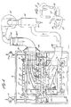
- reference numeral 6 indicates the general enclosure of the mattress heat treatment oven in which the conveyor system and the systems are arranged. hot air circulation.
- rotary support members or sprockets 7 ⁇ 7 are arranged in the lower part of the oven for mounting a lower endless conveyor, the upper strand and the lower strand are not shown in Figs. 1 a and 1b only by dashed lines, these strands of the conveyor appearing in more detail in 8a and 8b in FIGS. 2, 3 and 4.
- rotary support members or sprockets 9 ⁇ 9 are also provided for the upper conveyor which is not indicated in FIGS. 1 and 1b only by dashed lines, but the lower strand and the upper strand appear in more detail in 10a and 10b in Figs. 2, 3 and 4.
- Each of the conveyors is constituted by a number of pallets which are articulated with one another and carry rollers 12 suitable for running on the rolling tracks 13. The pallets carry transverse ribs 11. Transporters of this kind are driven by sprockets.
- the gypsies 9, as well as the raceways 13 for the upper conveyor, are mounted in a chassis 14 made of side members and cross members assembled, so that the position of the upper conveyor can be adjusted relative to that of the lower conveyor.
- This adjustment can be made using screw jacks 15 in a conventional manner which does not therefore fall within the scope of the invention.
- the distance between the strands 8a and 10a of the conveyors, which are the strands in contact with the fiber mat, can be modified to impose the desired density or thickness on the product being manufacturing.
- a conveyor shown schematically at 16 which is in this case a perforated conveyor of common use for the collection of fibers in order to form a sheet or a mattress.
- Suction boxes, as illustrated in 17, can be used to promote the collection of fibers and their retention in place on the conveyor.
- Suction fans 17a are connected to the suction boxes.
- the layer of fibers carried by the conveyor 16 is brought to the calender cylinders R1-R2, which are preferably adjustable so that it is possible to impose the thickness of the mattress entering the oven and, at the exit between the cylinders Rl-R2, the partially calendered mattress fits between the strands of the conveyors in the heat treatment oven.
- the primary or low pressure air circulation boxes are grouped in pairs.
- the zones or regions of the pairs being generally indicated in A, B, C, D, E and F.
- These pairs of boxes each consist of two generally rectangular boxes 18 and 19, which are closed on all sides, except that facing the strands 8a and 10a of the carriers.
- Each box 18 is on a fixed frame below the upper strand 8a of the lower conveyor and each box 19 is carried by the vertically adjustable frame 14 of the upper conveyor, so that the upper boxes accompany the upper conveyor when the position of this this is adjusted.
- Each box also includes a flue indicated at 20 and communicating with a sheath to admit or evacuate the treatment gas.
- the inlet and outlet flues are marked, respectively, by the signs "+" and "-". It should be noted that, in the first pair of boxes A, the inlet flue 20 is formed in the lower box 18 on the upstream side of the box relative to the direction of travel of the product in the oven and that the discharge flue is formed in the upper box 19 of this pair, near the downstream end.
- zone D occupied by the fourth pair of boxes the arrangement of the inlet and outlet ports is the same for pairs A and B.
- the arrangement of the inlet ports and evacuation is as indicated above for the pair C, and for the pair F the arrangement is the same as for the boxes D.
- the number of treatment zones and circulation boxes can be greater or less depending on the nature of the product produced.
- the passage of gas in certain boxes can be interrupted, if the thing is desired.
- the general enclosure of the oven 6 is provided with a system of gas evacuation comprising the ducts 21 and the suction fan 22, which sends the gas leaving the interior of the oven in a suitable precipitation device 23 which separates the suspended solids during the passage of the gas.
- the walls of the oven 6 in fact constitute a hood surrounding the internal organs of the oven, in particular the boxes and collectors for circulation of heated gas and the gas which spreads through the leaks is evacuated from the enclosure of the oven. by the evacuation system described immediately above.
- Fig. 2 is an enlarged view in cross section through the low pressure boxes of zone C. It can be seen that the gas intake duct 24 is connected to the upper box or inlet box 19 and that the duct d gas evacuation 25 is connected to the lower box or evacuation box 18. Baffles 19a distribute the incoming gas over the width of the conveyor and therefore over the width of the mattress being treated. The gas collected in the exhaust duct 25 is brought to a heater 26 with which is associated a burner 27 and is sucked through the heater by the fan 28 and propelled by the latter into the intake duct 24.
- This system of Heating and gas circulation can be used for more than one pair of low pressure chambers, but, if desired, separate circulation systems can be put into operation.
- the intake duct 24 passes through an over-calibrated orifice 29 in the wall of the oven and a flexible bellows 30 can be used to make the seal between the intake duct and oven wall.
- the sheath 24 is provided with a sliding seal 24a allowing vertical adjustment.
- these conveyors are formed of pallets 11 hinged together in an endless loop so that such a loop constitutes a conveyor.
- the different pallets extend over the entire width of the conveyor and are provided with rollers 12 as indicated above, each pallet comprising a plate 31 which is perforated at intervals over the width of the conveyor (as it is clearly visible in Fig.
- ribs 32 constituting transverse passages, which pass through the pallets for the passage of gas from the low pressure intake boxes or manifolds high pressure intake through the mattress carried by the carriers, then through the orifices and passages of the pallets of the other carrier into the boxes or evacuation collectors.
- a high pressure manifold system HP is associated with the pair of low pressure boxes E, this high pressure system and the pair of low pressure boxes E being shown on a larger scale and in longitudinal section in fig. 3 and on a larger scale and in cross section in FIG. 4. It appears from the examination of FIGS. 1b and 3 that the high pressure manifold system is substantially smaller than the low pressure chambers and moreover that the high pressure manifold system is housed in the low pressure chambers.
- the high pressure intake manifold is indicated at 33 and it appears from a comparison of FIGS.
- An intake duct 34 communicates with the high pressure intake manifold and passes through an over-calibrated orifice 35 in the wall of the oven, the orifice being sealed by a flexible bellows 36.
- the duct 34 comprises a sliding seal 34a allowing vertical movement.
- baffles 37 distribute the gas under high pressure over the width of the conveyor.
- a high pressure evacuation manifold 38 is arranged below the strand 8a of the lower conveyor and communicates with the sheath 39 to evacuate the gas under high pressure after it has passed through the mattress being treated.
- the sheath 39 brings the gas sucked into the heater 40 provided with a burner 41 and from where the gas is sucked by the fan 42 which returns it to the intake sheath 34.
- the high pressure heating and circulation system comprising the heater 40 and the fan 42 may be used for more than one high pressure system or, alternatively, separate heaters and fans may be used. commissioned for different high pressure systems.
- distribution baffles 37 are arranged in the intake manifold 33, they are not necessary and are preferably omitted in the exhaust manifold 38.
- FIG. 5 schematically illustrates a variant of the heater which can be used to heat the gases under high pressure in the circulation system.
- a heat exchanger shown schematically at 43 is mounted in the exhaust manifold 39 upstream of the gas path in the fan or blower 42.
- FIG. 5 also illustrates an alternative arrangement of the high pressure intake and exhaust manifolds 33 and 38 in the illustrated case the intake manifold 33 is mounted under treated mattress and the exhaust manifold 38 above the mattress.
- a chassis 44 is provided on each side of the upper or intake manifold 33 and serves as a mount for two partitions 45 arranged on either side of the manifold 33.
- Each of the partitions is mounted pivot, as indicated in 46, so that it can be raised away from the upper face of the strand 10a of the conveyor.
- the partition 45 carries a flange cooperating with a stop 47 which serves to limit the downward movement of the partition and thus prevents the latter from making contact with the upper face of the strand 10a of the conveyor.
- Each of the partitions 45 is shaped in the form of a bowl and extends over the entire width of the conveyor and it is within the scope of the invention that these partitions have a flat lower face and are mounted in close proximity to the upper face of the strand 10a of the conveyor, so as to create a seal preventing any significant lateral leakage of the gas under high pressure used in the high pressure distributor system. In a typical installation and in the normal service position of each partition 45, this is located at a distance of the order of a few millimeters, for example approximately 3 to 5 mm, from the upper face of the strand 10a.
- movable sealing partitions are designed so that they can normally be brought much closer to the transporter than would be possible if they were fixed.
- the partitions can easily move away from the conveyor in the event that irregular deposits of resin or fibers accumulate on the conveyor, as happens from time to time during the operation of such an installation.
- the partitions 45 placed above the conveyor, fall automatically by gravity into place in close proximity to the conveyor after being removed by a possible deposit of resin or fibers.
- the width of the flat bottom of each of the bowl partitions 45 is preferably at least double the spacing between two. reinforcement ribs of the conveyor pallets so that the desired seal is ensured regardless of the position of the conveyor ribs relative to the partition along the path of the conveyor.
- Similar movable partitions 48 are associated with the strand 8a of the lower conveyor and are designed to deviate downwards from the lower face of the strand 8a of the conveyor in the direction of which they are brought back by springs 49. Pivots and similar stops are provided for the lower partitions 48, but due to the fact that they are driven back downwards by obstacles encountered when the conveyor strand passes into the high pressure system, the return of the partitions 48 to their normal service position is ensured by the springs rather than gravity.
- Each of the partitions 45, 45 and 48, 48 has an inclined surface indicated at 50 at the upstream part to facilitate movement under the effect of foreign bodies brought in by the carriers.
- the intake manifold 33 is housed above the conveyor and inside the low pressure circulation box with which the intake duct communicates of gas under low pressure, the evacuation manifold of the high pressure system being housed in the evacuation chamber of the low pressure system.
- FIG. 1 c two high pressure circulation systems are shown inside a single pair of low pressure chambers.
- the high pressure intake manifolds 33a and 33b are placed side by side with an intermediate movable sealing partition such as the sealing partitions described above with reference to FIG. 3 and the cooperating high pressure evacuation collectors 38a and 38b are housed in the low pressure evacuation box below the mattress, a movable partition being disposed between the two high pressure evacuation collectors of the same type as described above with reference to FIG. 3.
- Movable partitions are also associated with the manifold system of Fig. 1 in a manner now evident.
- high pressure air circulation systems can be used in combination with any of the treatment zones A to F, it is particularly advantageous to use such high pressure circulation systems in combination with low-pressure circulation chambers downstream of a place located approximately in the middle of the journey and preferably at least two-thirds of the length of the journey from the entry into the oven.
- two high pressure circulation systems are generally indicated in HP 1 and HP2 and are located respectively in the low pressure zones E and F, which are the latter two in the embodiment illustrated by Fig. 1 a and 1b.
- the high pressure intake manifolds When two high pressure systems are housed in a single pair of low pressure boxes, it is preferable to arrange the high pressure intake manifolds on the same side of the mattress and preferably in the low pressure intake box, because the inconveniences due to leaks and therefore the heat losses are reduced to a minimum.
- the conditions of service vary depending on a number of factors, including the thickness and density of the mattress being manufactured, the composition and properties of the binder used and the amount of binder.
- some general information on working conditions is given below.
- the low pressure circulation maintained by means of the circulation chambers 18 and 19 in zones A to F inclusive includes certain zones in which the gas rises through the mattress and d others in which it descends through the mattress. It is also in accordance with the invention that the gas flowing through the chambers 18 and 19 in different zones may be at different temperatures depending on the properties of the mattress and the binder, as is already known for the operation of mattress heat treatment ovens comprising several treatment zones.
- a suitable temperature range for the gas admitted to the circulation boxes 18 and 19 ranges from about 150 to about 300 ° C for common fiber binders, for example phenol / formaldehyde resin binders.
- the maintained pressure conditions can also vary and the pressure can be measured in different ways.
- the pressure in the intake box and that in the exhaust box obviously differ due to the pressure drop during the passage of gas through the mattress.
- the pressure in the intake box of low pressure systems is around 5 to 30 mm of water.
- high pressure circulation system for example, in the case illustrated in FIG. 1 b, where a high pressure system HP1 is housed in the low pressure zone E and another high pressure system HP2 is housed in the low pressure zone F and it is in accordance with the invention that one of these high systems pressure is designed to pass the process gas through the mattress in one direction and the other high pressure system to pass the gas through the mattress in the opposite direction.
- the high pressure system HP1 is shown as delivering the gas in the downward direction and the high pressure system HP2, shown as supplying the gas in the upward direction. This measure ensures substantial uniformity of treatment throughout the thickness of the mattress.
- the high pressure system can operate over a large pressure range, but in general its pressure should be at least a few times and preferably at least 10 to 20 times the pressure prevailing in the low pressure system.
- the pressure in the intake manifolds of the high pressure system can be more than about 300 to 600 mm of water.
- the temperature in high pressure systems is preferably about 200 to about 350 ° C.
- the total volume of gas used in low pressure circulation systems can be around 30,000 Nm / 3 hours.
- the high pressure systems consume heated gas in an amount of about 5,000 Nm 3 / hour.
- the high pressure gas is confined in localized regions relatively smaller than those occupied by the low pressure gas and these localized regions, in a typical case, can represent approximately 10% of the extent of the treatment zones established by low pressure chambers.
- the temperatures and pressures also vary with the speed of travel of the mattress during manufacture and with the number of treatment zones in the oven for the thermal treatment of the mattress.
- the use according to the invention of a high pressure air circulation system and a low pressure air circulation system is particularly effective in various respects, in particular because the hardening of a binder determined can be performed in a smaller number of treatment zones and on a significantly shorter path in the oven. This is due to the fact that high pressure systems are particularly effective in bringing the core of the mattress to the heat treatment temperature in a short time. Another advantage is that high pressure systems quickly bring the temperature of the binder to the value where the exothermic reaction takes place, even at the heart of the mattress, and this temperature is then maintained more conveniently even beyond the occupied localized region. by high pressure collectors.
Landscapes
- Engineering & Computer Science (AREA)
- Mechanical Engineering (AREA)
- Textile Engineering (AREA)
- General Engineering & Computer Science (AREA)
- Physics & Mathematics (AREA)
- Health & Medical Sciences (AREA)
- Oral & Maxillofacial Surgery (AREA)
- Thermal Sciences (AREA)
- Treatment Of Fiber Materials (AREA)
- Tunnel Furnaces (AREA)
- Nonwoven Fabrics (AREA)
- Drying Of Solid Materials (AREA)
Applications Claiming Priority (2)
| Application Number | Priority Date | Filing Date | Title |
|---|---|---|---|
| FR777717642A FR2394041A1 (fr) | 1977-06-09 | 1977-06-09 | Etuvage de bandes continues de fibres isolantes |
| FR7717642 | 1977-06-09 |
Publications (2)
| Publication Number | Publication Date |
|---|---|
| EP0000111A1 EP0000111A1 (fr) | 1978-12-20 |
| EP0000111B1 true EP0000111B1 (fr) | 1981-05-13 |
Family
ID=9191871
Family Applications (1)
| Application Number | Title | Priority Date | Filing Date |
|---|---|---|---|
| EP78400014A Expired EP0000111B1 (fr) | 1977-06-09 | 1978-06-07 | Appareil pour le traitement thermique d'un matelas de fibres portant un liant thermoducissable |
Country Status (26)
| Country | Link |
|---|---|
| EP (1) | EP0000111B1 (fi) |
| JP (1) | JPS546976A (fi) |
| AR (1) | AR215712A1 (fi) |
| AU (1) | AU516259B2 (fi) |
| BR (1) | BR7803686A (fi) |
| CA (1) | CA1119373A (fi) |
| CS (1) | CS247054B2 (fi) |
| DD (1) | DD136510A5 (fi) |
| DE (1) | DE2860695D1 (fi) |
| DK (1) | DK255878A (fi) |
| ES (1) | ES470672A1 (fi) |
| FI (1) | FI63071C (fi) |
| FR (1) | FR2394041A1 (fi) |
| GR (1) | GR66393B (fi) |
| IE (1) | IE47077B1 (fi) |
| IL (1) | IL54873A (fi) |
| IT (1) | IT1096627B (fi) |
| MX (1) | MX146602A (fi) |
| NO (1) | NO148183C (fi) |
| NZ (1) | NZ187494A (fi) |
| PH (1) | PH16009A (fi) |
| PL (1) | PL115148B1 (fi) |
| PT (1) | PT68162A (fi) |
| TR (1) | TR20054A (fi) |
| YU (1) | YU136978A (fi) |
| ZA (1) | ZA782948B (fi) |
Families Citing this family (14)
| Publication number | Priority date | Publication date | Assignee | Title |
|---|---|---|---|---|
| JPS57205569A (en) * | 1981-06-05 | 1982-12-16 | Asahi Chemical Ind | Method and apparatus for producing nonwoven fabric |
| FR2640546B1 (fr) * | 1988-12-21 | 1991-04-12 | Saint Gobain Isover | Procede d'obtention d'un panneau d'isolation surface a base de fibres minerales |
| DE4208283A1 (de) * | 1992-03-13 | 1993-09-16 | Troester Maschf Paul | Anlage zum vulkanisieren von aus kautschukmischungen hergestellten erzeugnissen |
| US6473998B1 (en) | 1999-04-30 | 2002-11-05 | Superba (Societe Anonyme) | Process for pre-drying textile filaments after wet treatment and device for practicing this method |
| FR2792953B1 (fr) * | 1999-04-30 | 2001-06-22 | Superba Sa | Procede de presechage de fils textiles apres traitement humide et dispositif pour la mise en oeuvre de ce procede |
| EP1351030A1 (de) * | 2002-04-02 | 2003-10-08 | Solipat Ag | Vorrichtung und Verfahren zum Verfestigen eines Faserverbundes |
| GB0706144D0 (en) | 2007-03-30 | 2007-05-09 | Knauf Insulation Ltd | Curing oven for mineral wool mat |
| FR2984371B1 (fr) * | 2011-12-20 | 2014-01-10 | Saint Gobain Isover | Etuve pour la fabrication d'un produit en laine minerale |
| FR2994201B1 (fr) | 2012-07-31 | 2014-08-08 | Saint Gobain Isover | Procede de cuisson d'un matelas continu de fibres minerales ou vegetales |
| JP6503920B2 (ja) * | 2015-06-23 | 2019-04-24 | 三菱ケミカル株式会社 | 通気乾燥装置、およびそれを用いたバインダー含有無機繊維成形体の製造方法 |
| FR3062717B1 (fr) | 2017-02-07 | 2021-01-01 | Nexter Systems | Boitier destine a etre dispose sur un vehicule et systeme d'arme comprenant un tel boitier. |
| FR3106655B1 (fr) * | 2020-01-24 | 2021-12-24 | Alfi Technonogies | Etuve de polymérisation pour matelas en fibres minérales |
| FR3136784A1 (fr) * | 2022-06-20 | 2023-12-22 | Saint-Gobain Isover | Système et procédé de réticulation d’un matelas continu de fibres minérales et/ou végétales |
| FR3136785A1 (fr) * | 2022-06-20 | 2023-12-22 | Saint-Gobain Isover | Système et procédé pour la fabrication d’un matelas continu de fibres minérales et/ou végétales |
Family Cites Families (6)
| Publication number | Priority date | Publication date | Assignee | Title |
|---|---|---|---|---|
| BE507130A (fi) * | 1950-11-15 | |||
| US2997096A (en) * | 1957-05-16 | 1961-08-22 | Owens Corning Fiberglass Corp | Multiple stage methods and apparatus for curing the binder of fibrous glass masses |
| US3096161A (en) * | 1957-09-16 | 1963-07-02 | Owens Corning Fiberglass Corp | Heat setting of binder of fibrous masses |
| US3084448A (en) * | 1958-10-22 | 1963-04-09 | Dungler Julien | Thermal treatments at high pressure |
| JPS4841470A (fi) * | 1971-09-29 | 1973-06-18 | ||
| US3981708A (en) * | 1975-01-15 | 1976-09-21 | Johns-Manville Corporation | System for producing blankets and webs of mineral fibers |
-
1977
- 1977-06-09 FR FR777717642A patent/FR2394041A1/fr active Granted
-
1978
- 1978-05-23 ZA ZA00782948A patent/ZA782948B/xx unknown
- 1978-05-29 CA CA000304353A patent/CA1119373A/en not_active Expired
- 1978-05-31 AR AR272433A patent/AR215712A1/es active
- 1978-06-02 IE IE1131/78A patent/IE47077B1/en unknown
- 1978-06-05 IT IT24226/78A patent/IT1096627B/it active
- 1978-06-05 JP JP6685178A patent/JPS546976A/ja active Pending
- 1978-06-06 TR TR20054A patent/TR20054A/xx unknown
- 1978-06-07 DE DE7878400014T patent/DE2860695D1/de not_active Expired
- 1978-06-07 GR GR56451A patent/GR66393B/el unknown
- 1978-06-07 IL IL54873A patent/IL54873A/xx unknown
- 1978-06-07 EP EP78400014A patent/EP0000111B1/fr not_active Expired
- 1978-06-07 FI FI781824A patent/FI63071C/fi not_active IP Right Cessation
- 1978-06-08 YU YU01369/78A patent/YU136978A/xx unknown
- 1978-06-08 BR BR787803686A patent/BR7803686A/pt unknown
- 1978-06-08 NZ NZ187494A patent/NZ187494A/xx unknown
- 1978-06-08 AU AU36943/78A patent/AU516259B2/en not_active Expired
- 1978-06-08 NO NO782002A patent/NO148183C/no unknown
- 1978-06-08 PT PT68162A patent/PT68162A/pt unknown
- 1978-06-08 MX MX173741A patent/MX146602A/es unknown
- 1978-06-08 DK DK255878A patent/DK255878A/da not_active Application Discontinuation
- 1978-06-09 CS CS783786A patent/CS247054B2/cs unknown
- 1978-06-09 PH PH21247A patent/PH16009A/en unknown
- 1978-06-09 ES ES470672A patent/ES470672A1/es not_active Expired
- 1978-06-09 DD DD78205916A patent/DD136510A5/xx unknown
- 1978-06-09 PL PL1978207522A patent/PL115148B1/pl unknown
Also Published As
| Publication number | Publication date |
|---|---|
| AU3694378A (en) | 1979-12-13 |
| FR2394041A1 (fr) | 1979-01-05 |
| MX146602A (es) | 1982-07-14 |
| NO148183C (no) | 1984-12-12 |
| JPS546976A (en) | 1979-01-19 |
| EP0000111A1 (fr) | 1978-12-20 |
| NZ187494A (en) | 1982-05-25 |
| CS247054B2 (en) | 1986-11-13 |
| FI781824A (fi) | 1978-12-10 |
| FI63071C (fi) | 1984-08-08 |
| DE2860695D1 (en) | 1981-08-20 |
| DK255878A (da) | 1978-12-10 |
| TR20054A (tr) | 1980-07-01 |
| AU516259B2 (en) | 1981-05-28 |
| PL115148B1 (en) | 1981-03-31 |
| IL54873A (en) | 1982-01-31 |
| FI63071B (fi) | 1982-12-31 |
| AR215712A1 (es) | 1979-10-31 |
| FR2394041B1 (fi) | 1980-08-08 |
| NO782002L (no) | 1978-12-12 |
| GR66393B (fi) | 1981-03-20 |
| ES470672A1 (es) | 1979-02-01 |
| PH16009A (en) | 1983-05-20 |
| BR7803686A (pt) | 1979-01-16 |
| NO148183B (no) | 1983-05-16 |
| PT68162A (fr) | 1978-07-01 |
| IE781131L (en) | 1978-12-09 |
| IE47077B1 (en) | 1983-12-14 |
| YU136978A (en) | 1983-01-21 |
| DD136510A5 (de) | 1979-07-11 |
| PL207522A1 (pl) | 1979-02-26 |
| CA1119373A (en) | 1982-03-09 |
| IT7824226A0 (it) | 1978-06-05 |
| IL54873A0 (en) | 1978-08-31 |
| ZA782948B (en) | 1979-05-30 |
| IT1096627B (it) | 1985-08-26 |
Similar Documents
| Publication | Publication Date | Title |
|---|---|---|
| EP0000111B1 (fr) | Appareil pour le traitement thermique d'un matelas de fibres portant un liant thermoducissable | |
| EP0821744B1 (fr) | Procede d'infiltration chimique en phase vapeur pour la densification de substrats poreux disposes en piles annulaires | |
| EP2627960B1 (fr) | Etuve pour la fabrication d'un produit en laine minerale | |
| EP3311088B1 (fr) | Caisson pour etuve de reticulation et etuve de reticulation d'un matelas continu de fibres minerales ou vegetales | |
| EP0107566B1 (fr) | Procédé pour la transport de feuilles de verre portées à leur température de déformation et dispositif pour sa mise en oeuvre | |
| EP1370707B1 (fr) | Procede pour la densification par infiltration chimique en phase vapeur de substrats poreux ayant un passage central | |
| CA2579486C (fr) | Procede de durcissement d'un liant sur des fibres isolantes | |
| FR1465011A (fr) | Procédé et installation pour la cuisson des objets en matière céramique | |
| WO2001042542A1 (fr) | Boite d'etancheite pour une enceinte de traitement en continu de produit mince en bande | |
| FR2905286A1 (fr) | Procede et dispositif de traitement physique et/ou chimique de produits en vrac au moyen d'un fluide gazeux. | |
| EP0199649A1 (fr) | Revêtement du verre fabriqué dans une installation de flottage par des composés pyrolysables en poudre | |
| FR2478150A1 (fr) | Machine de traitement thermique de fils textiles | |
| EP3048892A1 (fr) | Procédé de cuisson de produits de boulangerie, viennoiserie et pâtisserie avec préchauffage direct, et ses dispositifs de mise en oeuvre | |
| FR3055771A1 (fr) | Module de cuisson de four tunnel lineaire pour produits de boulangerie, viennoiserie et similaires et four tunnel lineaire comportant au moins un tel module | |
| EP1717532A1 (fr) | Procédé de réglage du flux de fluide de séchage | |
| WO2023247499A1 (fr) | Système et procédé pour la fabrication d'un matelas continu de fibres minérales et/ou végétales | |
| WO2023247498A1 (fr) | Système et procédé de réticulation d'un matelas continu de fibres minérales et/ou végétales | |
| EP0094893B1 (fr) | Procédé et installation de traitement d'une matière solide réduite en morceaux | |
| EP1841577B1 (fr) | Four de cuisson a gaz en continu notamment de produits en caoutchouc | |
| FR2520770A1 (fr) | Procede et dispositif pour secher en continu les feuilles de papier et de carton | |
| BE540021A (fi) | ||
| CH437656A (fr) | Four pour produits céramiques | |
| EP0557202A1 (fr) | Four pour la purification de matières polluées | |
| BE560321A (fi) |
Legal Events
| Date | Code | Title | Description |
|---|---|---|---|
| PUAI | Public reference made under article 153(3) epc to a published international application that has entered the european phase |
Free format text: ORIGINAL CODE: 0009012 |
|
| AK | Designated contracting states |
Kind code of ref document: A1 Designated state(s): BE CH DE FR GB LU NL SE |
|
| 17P | Request for examination filed | ||
| GRAA | (expected) grant |
Free format text: ORIGINAL CODE: 0009210 |
|
| AK | Designated contracting states |
Kind code of ref document: B1 Designated state(s): BE CH DE FR GB LU NL SE |
|
| PG25 | Lapsed in a contracting state [announced via postgrant information from national office to epo] |
Ref country code: LU Free format text: LAPSE BECAUSE OF NON-PAYMENT OF DUE FEES Effective date: 19810630 |
|
| PGFP | Annual fee paid to national office [announced via postgrant information from national office to epo] |
Ref country code: NL Payment date: 19810630 Year of fee payment: 4 |
|
| REF | Corresponds to: |
Ref document number: 2860695 Country of ref document: DE Date of ref document: 19810820 |
|
| KL | Correction list |
Free format text: 81/02 PATENTANSPRUCH |
|
| PG25 | Lapsed in a contracting state [announced via postgrant information from national office to epo] |
Ref country code: NL Effective date: 19830101 |
|
| NLV4 | Nl: lapsed or anulled due to non-payment of the annual fee | ||
| GBPC | Gb: european patent ceased through non-payment of renewal fee | ||
| PGFP | Annual fee paid to national office [announced via postgrant information from national office to epo] |
Ref country code: LU Payment date: 19830707 Year of fee payment: 6 |
|
| PGFP | Annual fee paid to national office [announced via postgrant information from national office to epo] |
Ref country code: FR Payment date: 19840329 Year of fee payment: 7 |
|
| PGFP | Annual fee paid to national office [announced via postgrant information from national office to epo] |
Ref country code: CH Payment date: 19840419 Year of fee payment: 7 |
|
| PGFP | Annual fee paid to national office [announced via postgrant information from national office to epo] |
Ref country code: SE Payment date: 19840630 Year of fee payment: 7 Ref country code: BE Payment date: 19840630 Year of fee payment: 7 |
|
| PGFP | Annual fee paid to national office [announced via postgrant information from national office to epo] |
Ref country code: DE Payment date: 19840814 Year of fee payment: 7 |
|
| PG25 | Lapsed in a contracting state [announced via postgrant information from national office to epo] |
Ref country code: SE Effective date: 19860608 |
|
| PG25 | Lapsed in a contracting state [announced via postgrant information from national office to epo] |
Ref country code: FR Free format text: LAPSE BECAUSE OF NON-PAYMENT OF DUE FEES Effective date: 19870227 |
|
| REG | Reference to a national code |
Ref country code: FR Ref legal event code: ST |
|
| PG25 | Lapsed in a contracting state [announced via postgrant information from national office to epo] |
Ref country code: CH Effective date: 19870630 |
|
| BERE | Be: lapsed |
Owner name: SAINT-GOBAIN INDUSTRIES Effective date: 19870630 |
|
| REG | Reference to a national code |
Ref country code: CH Ref legal event code: PL |
|
| PG25 | Lapsed in a contracting state [announced via postgrant information from national office to epo] |
Ref country code: DE Effective date: 19880301 |
|
| PG25 | Lapsed in a contracting state [announced via postgrant information from national office to epo] |
Ref country code: GB Effective date: 19881117 |
|
| PG25 | Lapsed in a contracting state [announced via postgrant information from national office to epo] |
Ref country code: BE Effective date: 19890630 |
|
| EUG | Se: european patent has lapsed |
Ref document number: 78400014.3 Effective date: 19870504 |
|
| PLBE | No opposition filed within time limit |
Free format text: ORIGINAL CODE: 0009261 |
|
| STAA | Information on the status of an ep patent application or granted ep patent |
Free format text: STATUS: NO OPPOSITION FILED WITHIN TIME LIMIT |