EP0821744B1 - Procede d'infiltration chimique en phase vapeur pour la densification de substrats poreux disposes en piles annulaires - Google Patents
Procede d'infiltration chimique en phase vapeur pour la densification de substrats poreux disposes en piles annulaires Download PDFInfo
- Publication number
- EP0821744B1 EP0821744B1 EP96913599A EP96913599A EP0821744B1 EP 0821744 B1 EP0821744 B1 EP 0821744B1 EP 96913599 A EP96913599 A EP 96913599A EP 96913599 A EP96913599 A EP 96913599A EP 0821744 B1 EP0821744 B1 EP 0821744B1
- Authority
- EP
- European Patent Office
- Prior art keywords
- substrates
- chamber
- preforms
- stack
- gas
- Prior art date
- Legal status (The legal status is an assumption and is not a legal conclusion. Google has not performed a legal analysis and makes no representation as to the accuracy of the status listed.)
- Expired - Lifetime
Links
Images


Classifications
-
- C—CHEMISTRY; METALLURGY
- C23—COATING METALLIC MATERIAL; COATING MATERIAL WITH METALLIC MATERIAL; CHEMICAL SURFACE TREATMENT; DIFFUSION TREATMENT OF METALLIC MATERIAL; COATING BY VACUUM EVAPORATION, BY SPUTTERING, BY ION IMPLANTATION OR BY CHEMICAL VAPOUR DEPOSITION, IN GENERAL; INHIBITING CORROSION OF METALLIC MATERIAL OR INCRUSTATION IN GENERAL
- C23C—COATING METALLIC MATERIAL; COATING MATERIAL WITH METALLIC MATERIAL; SURFACE TREATMENT OF METALLIC MATERIAL BY DIFFUSION INTO THE SURFACE, BY CHEMICAL CONVERSION OR SUBSTITUTION; COATING BY VACUUM EVAPORATION, BY SPUTTERING, BY ION IMPLANTATION OR BY CHEMICAL VAPOUR DEPOSITION, IN GENERAL
- C23C16/00—Chemical coating by decomposition of gaseous compounds, without leaving reaction products of surface material in the coating, i.e. chemical vapour deposition [CVD] processes
- C23C16/04—Coating on selected surface areas, e.g. using masks
- C23C16/045—Coating cavities or hollow spaces, e.g. interior of tubes; Infiltration of porous substrates
-
- C—CHEMISTRY; METALLURGY
- C23—COATING METALLIC MATERIAL; COATING MATERIAL WITH METALLIC MATERIAL; CHEMICAL SURFACE TREATMENT; DIFFUSION TREATMENT OF METALLIC MATERIAL; COATING BY VACUUM EVAPORATION, BY SPUTTERING, BY ION IMPLANTATION OR BY CHEMICAL VAPOUR DEPOSITION, IN GENERAL; INHIBITING CORROSION OF METALLIC MATERIAL OR INCRUSTATION IN GENERAL
- C23C—COATING METALLIC MATERIAL; COATING MATERIAL WITH METALLIC MATERIAL; SURFACE TREATMENT OF METALLIC MATERIAL BY DIFFUSION INTO THE SURFACE, BY CHEMICAL CONVERSION OR SUBSTITUTION; COATING BY VACUUM EVAPORATION, BY SPUTTERING, BY ION IMPLANTATION OR BY CHEMICAL VAPOUR DEPOSITION, IN GENERAL
- C23C16/00—Chemical coating by decomposition of gaseous compounds, without leaving reaction products of surface material in the coating, i.e. chemical vapour deposition [CVD] processes
- C23C16/44—Chemical coating by decomposition of gaseous compounds, without leaving reaction products of surface material in the coating, i.e. chemical vapour deposition [CVD] processes characterised by the method of coating
- C23C16/455—Chemical coating by decomposition of gaseous compounds, without leaving reaction products of surface material in the coating, i.e. chemical vapour deposition [CVD] processes characterised by the method of coating characterised by the method used for introducing gases into reaction chamber or for modifying gas flows in reaction chamber
-
- C—CHEMISTRY; METALLURGY
- C23—COATING METALLIC MATERIAL; COATING MATERIAL WITH METALLIC MATERIAL; CHEMICAL SURFACE TREATMENT; DIFFUSION TREATMENT OF METALLIC MATERIAL; COATING BY VACUUM EVAPORATION, BY SPUTTERING, BY ION IMPLANTATION OR BY CHEMICAL VAPOUR DEPOSITION, IN GENERAL; INHIBITING CORROSION OF METALLIC MATERIAL OR INCRUSTATION IN GENERAL
- C23C—COATING METALLIC MATERIAL; COATING MATERIAL WITH METALLIC MATERIAL; SURFACE TREATMENT OF METALLIC MATERIAL BY DIFFUSION INTO THE SURFACE, BY CHEMICAL CONVERSION OR SUBSTITUTION; COATING BY VACUUM EVAPORATION, BY SPUTTERING, BY ION IMPLANTATION OR BY CHEMICAL VAPOUR DEPOSITION, IN GENERAL
- C23C16/00—Chemical coating by decomposition of gaseous compounds, without leaving reaction products of surface material in the coating, i.e. chemical vapour deposition [CVD] processes
- C23C16/44—Chemical coating by decomposition of gaseous compounds, without leaving reaction products of surface material in the coating, i.e. chemical vapour deposition [CVD] processes characterised by the method of coating
- C23C16/458—Chemical coating by decomposition of gaseous compounds, without leaving reaction products of surface material in the coating, i.e. chemical vapour deposition [CVD] processes characterised by the method of coating characterised by the method used for supporting substrates in the reaction chamber
Definitions
- the present invention relates to a process for chemical infiltration into vapor phase for the densification of porous substrates arranged in annular piles, that is to say substrates having substantially a form of revolution with a passage or central opening which are arranged in at least one pile delimiting a internal passage formed by the central openings of the substrates, or of the substrates having a shape not necessarily annular but which are arranged to form a stack with an interior passage delimited by the stacked substrates.
- the field of application of the invention is in particular the manufacture of composite material parts comprising a porous substrate, or preform densified by a matrix.
- thermostructural composite material consisting of a fibrous preform refractory (carbon or ceramic fibers, for example) densified by a matrix refractory (carbon or ceramic, for example)
- CFRP carbon-carbon composite
- brake discs in particular aircraft brakes, made of C-C composites.
- Densification of porous substrates by chemical phase infiltration vapor consists in placing the substrates in a reaction chamber of a infiltration installation by means of support tools and to be admitted in the chamber a gas phase of which one or more constituents are precursors of the material to be deposited within the substrates in order to ensure their densification.
- the infiltration conditions, in particular composition and flow rate of the gas phase, and temperature and pressure in the chamber are chosen to allow diffusion of the gas phase within the accessible internal porosity of the substrates so that there either deposited the desired material by decomposition of a constituent of the phase gas or reaction between several constituents thereof.
- the carbon precursor is an alkane, an alkyl or an alkene, generally of propane, methane or a mixture of both. Infiltration is carried out at a temperature of approximately 1000 ° C. under a pressure for example of approximately 1 kPa.
- the conditions for chemical vapor infiltration of materials other than carbon, in particular ceramic materials, are also well known. We may refer in particular to document FR-A-2 401 888.
- the reaction chamber In an industrial phase chemical infiltration facility steam, it is usual to load the reaction chamber with several substrates or preforms to be densified simultaneously, using a support tool including in particular trays and spacers.
- the preforms When the preforms are annular, they can be arranged in stacks in a longitudinal direction of the reaction chamber.
- the gas phase containing the precursor (s) of material to be deposited within the preforms is allowed at a longitudinal end from the chamber while the residual gases are discharged at the opposite end from where they are extracted by pumping means.
- Means are usually intended to preheat the gas phase before it reaches the preforms at densify, for example in the form of perforated preheating plates by the gas phase admitted into the reaction chamber.
- a real difficulty encountered with infiltration processes known chemical vapor phase is to ensure the consistency of the microstructure of the material deposited within the substrates.
- the microstructure of the matrix is constant and conforms to that desired. So, in the example of pyrolytic carbon infiltration, or even minor variations in infiltration conditions can lead to changes in the microstructure of the pyrocarbon.
- Smooth laminar, rough laminar and isotropic pyrocarbons have very different properties. If we are looking for example to obtain a matrix pyrocarbon graphitable by heat treatment, a microstructure of the type rough laminar should preferably be obtained.
- An object of the present invention is to provide a method for avoid the aforementioned drawbacks, i.e. a chemical infiltration process in vapor phase to guarantee the constancy of the deposited microstructure within densified substrates, without requiring an increase in the flow of gas phase or a limitation of the load volume detrimental in term cost and performance of the installation.
- This goal is achieved through a phase chemical infiltration process steam to densify porous substrates with a material deposited therein, the method comprising: loading the substrates to be densified inside of a reaction chamber of an infiltration furnace, the substrates being arranged in at minus an annular or hollow pile which extends in a longitudinal direction of the room and which delimits an interior passage, with spaces made between substrates; admission, in the vicinity of a first longitudinal end of the reaction chamber, of a gas phase containing at least one precursor of the material to be deposited; and the discharge of residual gases through an outlet located at the near the longitudinal end of the reaction chamber opposite the first,
- the gas phase admitted into the reaction chamber is channeled to one of the two volumes formed by the interior and exterior of the or piles of substrates at its end closest to the first end longitudinal of the chamber; the volume in which the gas phase is channeled is closed at its end furthest from the first longitudinal end of bedroom ; and the spaces made between substrates open inside and outside of the or each stack so as to balance the pressure between the inside and outside of the or each stack; so that the circulation of the gas phase between admission into the room and the evacuation out of the room is done from the inside to the outside of the or each cell, or vice versa, the gas phase passing through the spaces between substrates, and diffusing within them.
- the gas phase admitted into the chamber is preheated by passing through a preheating zone located at the first end of the chamber, the gas phase channel inward or the exterior of the or each cell is produced at the outlet from the preheating zone.
- This process brings a clear improvement in the infiltration conditions, in order to achieve the desired goal, in particular in comparison with the processes known in which the gas phase is uniformly admitted into the chamber reaction, that is, when the chamber contains one or more stacks of substrates, with admission of the gas phase both inside and outside of the or each stack.
- a very important advantage of the method according to the invention is that the gas residence time in the reaction chamber can be considerably decreased, without changing the admission flow.
- the gas phase is allowed only in the volume represented either by the free space formed by the one or more central passages of the pile (s) of substrates, either by the free space around the or stacks of substrates.
- This volume is very significantly reduced compared to the total volume of the reaction chamber not occupied by the charge (substrates and support tool), that is to say the total volume of said free spaces, so that the same amount of gas flows much faster.
- the invention made it possible to easily limit the residence time to a value at most equal to 1 second. Reduced residence time prevents excessive maturation and an alteration of the gas phase which could have the effect of modifying microstructure of the deposited material.
- the pipeline for the admitted gas phase is carried out towards the smaller of the two volumes constituted by the interior and the exterior of the stack (s) of substrates.
- An additional advantage of the process is that forcing the gas phase to flow from the inside to the outside of the or each stack of substrates, or vice versa, there is a continuous renewal of the phase gas which bathes the surfaces of the substrates and from which the diffusion within substrates occurs.
- the gas phase is admitted to both volumes formed by the interior and exterior of the stack (s) of substrates at a end of these, and that these volumes are not closed at their other end, there is a preferential flow in the longitudinal direction.
- a continuous renewal of the gas phase cannot then be guaranteed within spaces between substrates, unless sufficiently large spaces are provided.
- a stagnation of the gas phase in the spaces between substrates means a time of long stay, therefore degradation of the microstructure of the deposited material.
- the substrates are spaced apart from each other by a distance large enough to promote the circulation of the gas phase between them, this is at the expense of the rate loading substrates into the infiltration oven.
- a circulation occurs necessarily continuously in the spaces between substrates, from the inside outward from the or each stack, or vice versa. It is then possible that the spaces between the substrates of a stack are of reduced width, simply sufficient to ensure pressure balancing between the inside and outside of the battery. This optimizes the filling rate of the oven with the substrates.
- the method according to the invention is advantageously implemented for densification of annular preforms of brake discs.
- Preforms can be arranged in a stack or in several parallel stacks in the direction longitudinal of the reaction chamber.
- the gas phase allowed is then channeled towards the inside of the stacks of preforms.
- the method according to the invention can also be implemented for the densification of other annular or substantially annular preforms, in particularly preforms of diverging propellant nozzles.
- Preforms are then arranged one above the other, preferably by making sure that a preform is partially engaged in another.
- the internal passage of each preform having a relatively large diameter, the gas phase allowed is then channeled to the outside of the or each stack of preforms, which provides normally less volume than the interior.
- the method according to the invention can also be implemented for the densification of substrates which are not necessarily annular, i.e. which do not have necessarily a form of revolution with a central passage or opening.
- the stacking of the substrates is carried out so as to form at least one annular or hollow pile with an interior passage bordered by the stacked substrates.
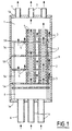
- FIG. 1 schematically illustrates a reaction chamber 1 of a chemical vapor infiltration plant.
- Room 1 has a shape general cylindrical with vertical axis.
- Annular fiber preforms 2 by example for the manufacture of composite aircraft brake discs carbon-carbon, are loaded into chamber 1 according to a configuration usual state of the art.
- the preforms 1 are arranged in several stacks which extend in the vertical longitudinal direction of chamber 1 (only two stacks are represented).
- the batteries are supported by a tool comprising trays lower loading 5a and intermediate 5b, provided with holes 5 for allow the passage of gases, and spacers 5c between the plates.
- the assembly rests on the bottom 1a of the chamber.
- a gas phase containing a carbon precursor such as propane mixed with methane or natural gas, is introduced into chamber 1.
- the gas phase is brought by several pipes 6 which lead to the part bottom of the room in roughly evenly distributed locations.
- the residual gases are extracted at the upper part of the chamber by lines 7.
- the gas phase passes through a preheating zone 8 containing perforated preheating plates, before reach the lower loading platform 5a.
- Preheating trays being located in the room, they are constantly close to the temperature prevailing therein and allow efficient preheating of the gas phase.
- Heating inside the chamber is produced by a susceptor graphite 9 forming an armature electromagnetically coupled with an inductor (not shown).
- the susceptor 9 delimits the internal volume of the axis chamber vertical with the bottom crossed by the pipes 6 and a cover 1b crossed by the pipes 7.
- the bottom and the cover are also made of graphite, as is the different trays and spacers contained in the room.
- the densification of the fibrous preforms 2 is ensured, in a good manner known per se, by deposition within them of pyrolytic carbon produced by decomposition of the precursor contained in the gas phase diffusing inside accessible internal porosity of the preforms.
- the gas phase circulates in the chamber 1 between the preheating zone 8 and the outlet conduits 7 passing to the interior and exterior of the stacks of substrates 2. In order to allow access to the gas phase on the faces of the preforms 2, these are, in each stack, kept apart from each other by means of spacers 3 which provide spaces 4 between the substrates.
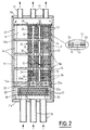
- the reaction chamber 11 has a cylindrical shape with vertical axis and is delimited by a graphite susceptor 19, a graphite bottom 11a closing the chamber at its bottom and a cover graphite 11b closing the chamber at its upper part.
- the infiltration installation comprises a inductor (not shown) which surrounds the susceptor 19.
- the inductor is coupled to the susceptor 19, forming an armature, in order to heat the chamber 11.
- the supply of the inductor is controlled so as to maintain at the desired value the temperature prevailing in chamber 11, measured by means of a sensor (not represented).
- the preforms 12 are carbon fiber preforms intended for be densified by a pyrolytic carbon matrix, for example preforms aircraft brake discs. They are made up of layers of carbon fibers superimposed linked together by needling. A method of making carbon fiber preforms made up of layers stacked flat and needled is described in particular in document FR-A-2 584 106.
- the gas phase containing one or more carbon precursors is introduced into chamber 11 via supply lines 16 leading to the lower end of the chamber through the bottom 11a.
- the gas phase giving pyrolytic carbon is for example constituted by propane, precursor carbon, and natural gas. Residual gases are extracted at the top of the chamber by means of evacuation pipes 17, through the cover 11b.
- the evacuation pipes are connected to a pumping device (not shown) allowing to establish the desired pressure inside the chamber.
- the gas phase entering the chamber 11 is preheated by passage through perforated preheating plates 20, spaced apart from one another others and from the bottom 11a by spacers 21.
- the preheating plates 20 and spacers 21 are made of graphite. By its passage through the plates 20, the phase gas is brought to a temperature close to that prevailing in chamber 11.
- the preheated gas phase then passes through a plateau diffuser 22 which rests on the bottom 11a via feet 23.
- the plate 22 presents passages 22a at regular intervals in order to distribute the phase almost uniform in gas throughout the section of the chamber 11.
- the preforms 12 are identical and arranged in vertical stacks 30 on circular support plates 15a, 15b. These have 15 holes and are kept spaced from each other by spacers 24.
- the support plates 15a, 15b and the spacers 24 are for example made of graphite.
- the support plate lower 15a rests on the diffuser plate 22 by means of shims 25 which keep spaced from the latter.
- a perforated upper circular plate 26 can be placed above the load in order to thermally homogenize the loading by forming a screen vis-à-vis the thermal radiation of preforms located at the top of the load.
- the plate 26 rests on the upper support plate by spacers 27.
- each stack 30 has several preforms 12 arranged one above the other according to the same vertical axis and extending in the interval between two plates.
- the preforms stacked on the different plates 15a, 15b are aligned vertically with the holes 15, the latter having a diameter equal to or slightly greater than the internal diameter of the preforms 12.
- the stacks 30 of aligned preforms vertically define a central passage in the form of a chimney 31 constituted by the central openings of the annular preforms 12 and the holes 15 in the trays. These passages 31 are closed at their upper part by screens full 32.
- the preheated gas phase from the diffuser plate 22 is channeled to the volume formed by the interior passages 31 of the stacks 30.
- the shims 25, arranged between the diffuser plate 22 and the support plate less than 15a, are rings with an internal diameter equal to or slightly greater than that of holes 15 and are aligned with them so that the gas phase is directed exclusively towards the passages 31.
- the diffuser plate 22 is provided with perforations 22a only with regard to the passages 31.
- Intermediate elements 33 of small thickness are arranged, in each stack, between the preforms 12 or, at least, between groups of preforms stacked. Similar intermediate elements are also arranged between the support plates and the first preforms which rest thereon, as well only between the last preforms of the stacks 30 and the screens 32. These elements spacers 33 provide leakage passages 34 of the gas phase between the inside and outside of the preforms, balancing the pressure between the passages 31 and the internal volume of the chamber 11, and allowing diffusion of the phase gas from the main planar faces of the preforms 12.
- phase gas from the preheating zone is channeled to the internal passages 31 batteries 30 and then circulates from the inside to the outside of each battery 30, in the volume 36 of the chamber external to the batteries 30, from where it is evacuated through the perforated tray 26 and outlet conduits 17.
- the circular passage section of these can be gradually reduced in the direction of circulation of the gas phase, bottom up.
- This restriction of the passage section can be obtained by inserting in each passage 31 a vertical central tooling element 35 of increasing section in the direction of flow of the gas flow.
- This element of tool 35 (only one is shown in Figure 2) in the form of "stalactite" is by example fixed under the screen 32 located at the upper part of the passage.
- a significant advantage of the process according to the invention is the reduction of the residence time of the gas phase in chamber 11, by comparison with a provision such as that of FIG. 1, for the same gas phase flow allowed, and constant renewal of the gas phase bathing the outer surfaces of the preforms is guaranteed.
- the residence time was measured in a reaction chamber of a industrial oven.
- the residence time measured between the intake ducts 16 and the top of the preform stacks, is 0.4 s with an arrangement as illustrated in Figure 2, while it is 1.8 s with the arrangement of Figure 1.
- This decrease in residence time due to the fact that the gas phase is channeled to a reduced volume constituted by the passages inside the piers, guarantees the consistency of the microstructure of the pyrocarbon deposited over the entire length of the stacks of preforms.
- the residence time can be greatly reduced with the process according to the invention, at constant residence time, the flow rate can be reduced in the same proportion. So if a sharp decrease in the time of stay is not useful for ensuring the consistency of the pyrocarbon microstructure deposited throughout the chamber, the flow rate of the gas phase can be reduced. The consumption of carbon precursor is then reduced, the size of the preheating zone can be reduced, without affecting the quality of preheating, thus increasing the useful volume of the reaction chamber, and the needs for pumping, to maintain the pressure in the chamber at the desired value, are reduced.
- the method according to the invention can be implemented with substrates porous annular other than those of FIG. 2, more generally with substrates having a shape of revolution with a central axial passage or opening.
- the porous substrates to be densified are fibrous preforms of diverging nozzles for propellants. It is by example of carbon fiber preforms intended to be densified by a pyrolytic carbon matrix.
- the reaction chamber 41 has a cylindrical shape with a vertical axis and is delimited by a graphite susceptor 49, a bottom 41a in graphite closing the chamber at the bottom and a cover in graphite 41b closing the chamber at its upper part.
- the susceptor 49 forms armature coupled to an inductor (not shown) surrounding the chamber.
- the gas phase containing one or more carbon precursors is introduced into the chamber 41 by supply lines 46 leading to the lower end of the chamber through the bottom 41a.
- the gas phase includes, for example, propane mixed with methane or natural gas.
- the residual gases are extracted at the top of the chamber by means of evacuation pipes 47, through the cover 41b.
- Evacuation pipes are connected to a pumping device (not shown) making it possible to establish the desired pressure inside the chamber.
- the gas phase entering chamber 41 is preheated in a preheating zone 48 by passage through preheating plates perforated 50 spaced from each other and from the bottom 41a by spacers 51.
- the preheating plates and the spacers 51 are for example made of graphite.
- the preheated gas phase then passes through a diffuser plate 52 having holes 52a and resting on the bottom 41a by means of feet.
- the preforms to be densified 42a, 42b, 42c, three in number example, are arranged so that their axes are substantially coincident with the vertical axis of the chamber 41, the diverging lines opening downwards.
- Their frustoconical shape, or in "egg cup” allows to arrange the preforms so that they are partially engaged with each other by forming a pile vertical, the tops of the preforms 42a, 42b being located inside the preforms 42b, 42c, respectively.
- the preforms are supported by means of horizontal plates respective, respectively a lower plate 45a, and two intermediate plates annulars 45b, 45c, kept spaced from each other by spacers 54.
- a circular upper plate rests on the upper preform 42a. He introduces a central opening 58 aligned with the vertical passage 51 formed by the alignment of the central channels of the preforms.
- the preheated gas phase from the diffuser plate 52 is channeled to a volume 66 located in the chamber 41 outside the preforms 42a, 42b, 42c.
- the preheated gas phase is channeled to holes calibrated 45 formed in a peripheral zone of the plate 45a, outside the zone where the downstream end of the preform 42a rests and also crosses holes calibrated 45 formed in the peripheral zones of the plates 45b, 45c, outside zones where the downstream ends of the preforms 42b, 42c rest.
- the tray lower 45a can be of annular shape, in order to be lightened, in which case a ring 53 is disposed between the diffuser plate 52 and the lower plate 45a so prevent access to the gas phase, towards passage 61 at the outlet of the preheating.
- the diffuser plate 52 is then only pierced in its zone peripheral.
- the intermediate support plates 45b, 45c have an opening central 67 whose wall may have a substantially frustoconical shape corresponding to the shape of the outer surface of the preforms they surround and the dimension of which is determined, as well as the height of the spacers 54, so that the plates 45b, 45c provide with the outer surfaces of the preforms 42a, 42b of predetermined reduced width intervals, for example one or a few tenths of a mm.
- a similar width interval is provided by means of spacers 64 between the top of the preform 42c and the plate higher 56.
- Additional tooling elements can be used such as annular seals 68 closing off the spaces between the outer edges of the plates supports 45a, 45b, 45c and the internal wall of the susceptor 49 and a frustoconical wall 69 which extends between the internal wall of the susceptor 49 and the upper plate 56, around the outer surface of the preform 42c in order to define a volume collapsed around it.
- the frustoconical wall 69 can be fixed under the plate higher 56.
- the support plates, spacers and other tool elements used in chamber 41 are for example graphite.
- the flow of the gas phase is done from the volume 66 outside the stack 60 towards the inside passage 61 where it is discharged through the pipes 47.
- the intervals between the preforms 42a, 42b and the intermediate support plates 45b, 45c, make it possible to balance the pressures between the inside and outside of the stack 60 and a continuous circulation of the gas phase in these intervals, so that the outer surfaces of the preforms 42a, 42b are constantly bathed in a gas phase renewed, to their summit.
- the interval between the top of the preform 42c and the upper plate 56 also allows pressure balancing and ensures the evacuation of the gas phase reaching the top of volume 66.
- the gas phase pipeline from the preheating zone to volume 66 outside the preforms, rather than to volume inside 61 is preferred to optimize the residence time.
- the volume outside the preforms is smaller than the interior volume and a greater reduction in residence time is achieved by directing the gas phase towards the smaller of these two volumes.
- the orifices 45 calibrated allow some control of flow flow, while the wall 69 contributes to reducing the volume 66, while leaving sufficient space around the preform 42c.
- the number of preforms can be different from three, depending on their dimensions and that of the infiltration chamber, and that it is not necessary that they are partially engaged in each other, the space between neighboring preforms can be closed, except for a width gap reduced by tool elements possibly supplementing the plates supports.
- the method according to the invention can be implemented with substrates not necessarily annular. It then suffices to arrange the substrates so as to divide the room into one or more volumes inside which the phase gas is admitted and one or more volumes of which the residual gas phase is evacuated after having passed between the substrates or having diffused through them.
- the substrates are arranged in one or more annular or hollow stacks having a interior passage delimited by the substrates.
- the substrates 70 have the shape of parallelepiped bars which are stacked in layers superimposed so as to form in each layer a closed polygon or almost closed, for example a triangle. In a pile, the bars 70 delimit thus an interior passage or volume 80 and an exterior volume 81. Spacers 71 are arranged between the bars 70 superimposed in order to hold them slightly spaced from each other.
- the substrates 70 are loaded into a chamber in a vertical stack (s) for example in a similar way to that illustrated in figure 2.
- the difference essential is to replace each annular substrate with several substrates arranged to obtain a polygonal shape.
- sharing the internal volume of the reaction chamber in two volumes, one in which the gas phase is admitted, and the other of which it is evacuated, can be achieved by combining the substrates and tool elements. This could in particular be so when substrates of shapes and / or different dimensions are loaded simultaneously.
- the invention is applicable to chemical vapor infiltration of materials other than carbon, in particular ceramics, in particular for the manufacture of parts in ceramic matrix composite material.
- gas phase supply and evacuation residual gases may be produced respectively at the upper part and at the lower part of the reaction chamber, that is to say with a flow of the gas phase in the chamber from top to bottom, without calling into question the principles of the invention.
Description
- la figure 1 illustre schématiquement un chargement d'une chambre de réaction d'une installation d'infiltration chimique en phase vapeur selon un procédé connu ;
- la figure 2 illustre schématiquement un exemple de mise en oeuvre du procédé selon l'invention pour la densification de préformes annulaires de disques de freins ;
- la figure 3 illustre schématiquement un autre exemple de mise en oeuvre du procédé selon l'invention pour la densification de préformes de divergents de tuyères de propulseurs ; et
- la figure 4 illustre schématiquement un autre chargement de substrats permettant la mise en oeuvre d'un procédé selon l'invention.
Claims (10)
- Procédé d'infiltration chimique en phase vapeur pour la densification de substrats poreux par un matériau déposé au sein de ceux-ci, le procédé comprenant : le chargement des substrats à densifier à l'intérieur d'une chambre de réaction d'un four d'infiltration, les substrats étant disposés en au moins une pile annulaire ou creuse qui s'étend dans une direction longitudinale de la chambre et qui délimite un passage intérieur avec des espaces ménagés entre des substrats ; l'admission, au voisinage d'une première extrémité longitudinale de la chambre de réaction, d'une phase gazeuse contenant au moins un précurseur du matériau à déposer; et l'évacuation de gaz résiduels à travers une sortie située au voisinage de l'extrémité longitudinale de la chambre de réaction opposée à la première,
ledit procédé étant caractérisé en ce que la phase gazeuse admise dans la chambre de réaction est canalisée vers l'un des deux volumes constitués par l'intérieur et l'extérieur de la ou des piles de substrats à son extrémité la plus proche de la première extrémité longitudinale de la chambre ; le volume dans lequel la phase gazeuse est canalisée est fermé à son extrémité la plus éloignée de la première extrémité longitudinale de la chambre ; et les espaces ménagés entre des substrats s'ouvrent à l'intérieur et à l'extérieur de la ou chaque pile de manière à équilibrer la pression entre l'intérieur et l'extérieur de la ou chaque pile; de sorte que la circulation de la phase gazeuse entre l'admission dans la chambre et l'évacuation hors de la chambre se fait de l'intérieur vers l'extérieur de la ou chaque pile, ou inversement, la phase gazeuse passant à travers les espaces entre substrats et diffusant au sein de ceux-ci. - Procédé selon la revendication 1 dans lequel la phase gazeuse admise dans la chambre est préchauffée par passage à travers une zone de préchauffage située à la première extrémité de la chambre,
caractérisé en ce que la canalisation de la phase gazeuse vers l'intérieur ou l'extérieur de la ou chaque pile est réalisée en sortie de la zone de préchauffage. - Procédé selon l'une quelconque des revendications 1 et 2, caractérisé en ce que la canalisation de la phase gazeuse admise est réalisée vers le plus petit des deux volumes constitués par l'intérieur et l'extérieur de la ou des piles de substrats.
- Procédé selon l'une quelconque des revendications 1 à 3, caractérisé en ce que l'on dispose, à l'intérieur de la ou chaque pile un élément de compensation ayant une section croissante dans le sens de l'écoulement de la phase gazeuse afin de compenser les fuites latérales à travers les substrats et entre ceux-ci par une réduction de la section de passage à l'intérieur de la pile de manière à maintenir une vitesse d'écoulement de la phase gazeuse sensiblement constante en direction longitudinale à l'intérieur de la pile.
- Procédé selon l'une quelconque des revendications 1 à 4 pour la densification de substrats ayant sensiblement une forme de révolution avec une ouverture centrale, caractérisé en ce que les substrats sont disposés en au moins une pile qui délimite un volume intérieur formé par les ouvertures centrales des substrats.
- Procédé selon la revendication 5 pour la densification de préformes annulaires pour des disques de frein, caractérisé en ce que l'on ménage entre les préformes de la ou chaque pile des espaces de moins de 5 mm de largeur.
- Procédé selon l'une quelconque des revendications 5 et 6, pour la densification de préformes annulaires pour de disques de frein, caractérisé en ce que l'on charge les préformes dans la chambre en plusieurs piles parallèles.
- Procédé selon la revendication 7, caractérisé en ce que la phase gazeuse admise dans la chambre est canalisée vers le volume intérieur des piles de préformes.
- Procédé selon la revendication 5 pour la densification de préformes de divergents de tuyères de propulseurs, caractérisé en ce que la phase gazeuse admise dans la chambre est canalisée vers le volume situé à l'extérieur des préformes.
- Procédé selon l'une quelconque des revendications 5 et 9, pour la densification de préformes de divergents de tuyères de propulseurs, caractérisé en ce que les préformes sont disposées les unes au-dessus des autres en faisant en sorte qu'une préforme soit partiellement engagée à l'intérieur d'une autre.
Applications Claiming Priority (3)
| Application Number | Priority Date | Filing Date | Title |
|---|---|---|---|
| FR9504586 | 1995-04-18 | ||
| FR9504586A FR2733254B1 (fr) | 1995-04-18 | 1995-04-18 | Procede d'infiltration chimique en phase vapeur pour la densification de substrats poreux disposes en piles annulaires |
| PCT/FR1996/000582 WO1996033295A1 (fr) | 1995-04-18 | 1996-04-17 | Procede d'infiltration chimique en phase vapeur pour la densification de substrats poreux disposes en piles annulaires |
Publications (2)
| Publication Number | Publication Date |
|---|---|
| EP0821744A1 EP0821744A1 (fr) | 1998-02-04 |
| EP0821744B1 true EP0821744B1 (fr) | 1999-08-04 |
Family
ID=9478184
Family Applications (1)
| Application Number | Title | Priority Date | Filing Date |
|---|---|---|---|
| EP96913599A Expired - Lifetime EP0821744B1 (fr) | 1995-04-18 | 1996-04-17 | Procede d'infiltration chimique en phase vapeur pour la densification de substrats poreux disposes en piles annulaires |
Country Status (9)
| Country | Link |
|---|---|
| US (1) | US5904957A (fr) |
| EP (1) | EP0821744B1 (fr) |
| JP (1) | JP3815796B2 (fr) |
| CA (1) | CA2218317C (fr) |
| DE (1) | DE69603593T2 (fr) |
| FR (1) | FR2733254B1 (fr) |
| RU (1) | RU2167217C2 (fr) |
| UA (1) | UA44309C2 (fr) |
| WO (1) | WO1996033295A1 (fr) |
Cited By (1)
| Publication number | Priority date | Publication date | Assignee | Title |
|---|---|---|---|---|
| EP1329534A2 (fr) * | 1998-10-23 | 2003-07-23 | Goodrich Corporation | Suzeptordeckel sowohl für Gasphaseninfiltration bzw. -Beschichtung als auch Wärmebehandlung |
Families Citing this family (67)
| Publication number | Priority date | Publication date | Assignee | Title |
|---|---|---|---|---|
| DE19607625C1 (de) * | 1996-02-29 | 1996-12-12 | Mtu Muenchen Gmbh | Vorrichtung und Verfahren zur Präparation und/oder Beschichtung der Oberflächen von Hohlbauteilen |
| FR2754813B1 (fr) * | 1996-10-18 | 1999-01-15 | Europ Propulsion | Densification de substrats poreux disposes en piles annulaires par infiltration chimique en phase vapeur a gradient de temperature |
| US6669988B2 (en) * | 2001-08-20 | 2003-12-30 | Goodrich Corporation | Hardware assembly for CVI/CVD processes |
| US7476419B2 (en) * | 1998-10-23 | 2009-01-13 | Goodrich Corporation | Method for measurement of weight during a CVI/CVD process |
| US6168827B1 (en) * | 1999-08-30 | 2001-01-02 | General Electric Company | Fiber coating method |
| CA2299225C (fr) * | 1999-09-06 | 2006-09-19 | Ishikawajima-Harima Heavy Industries Co., Ltd. | Methode et appareil pour la fabrication d'un element en composite a base de ceramique |
| FR2801304B1 (fr) * | 1999-11-24 | 2002-02-15 | Snecma | Procede de fabrication d'un bol en materiau composite thermostructural, notamment pour une installation de production de silicium monocristallin |
| FR2818291B1 (fr) * | 2000-12-19 | 2003-11-07 | Snecma Moteurs | Densification de substrats poreux creux par infiltration chimique en phase vapeur |
| FR2821859B1 (fr) * | 2001-03-06 | 2004-05-14 | Snecma Moteurs | Procede pour la densification par infiltration chimique en phase vapeur de substrats poreux ayant un passage central |
| FR2824084B1 (fr) | 2001-04-30 | 2003-08-01 | Messier Bugatti | Alimentation aiguilleteuse par bande spirale continue |
| US6793966B2 (en) | 2001-09-10 | 2004-09-21 | Howmet Research Corporation | Chemical vapor deposition apparatus and method |
| US6953605B2 (en) * | 2001-12-26 | 2005-10-11 | Messier-Bugatti | Method for densifying porous substrates by chemical vapour infiltration with preheated gas |
| FR2834713B1 (fr) * | 2002-01-15 | 2004-04-02 | Snecma Moteurs | Procede et installation pour la densification de substrats par infiltration chimique en phase vapeur |
| EP1452624B1 (fr) * | 2002-10-24 | 2008-06-11 | Goodrich Corporation | Procédé et dispositif de densification continu et discontinu par infiltration chimique en phase vapeur (CVI) |
| UA84862C2 (en) * | 2003-03-03 | 2008-12-10 | Месье-Бугатти | Substrate |
| US7335397B2 (en) * | 2004-02-16 | 2008-02-26 | Goodrich Corporation | Pressure gradient CVI/CVD apparatus and method |
| US7332195B2 (en) * | 2004-08-26 | 2008-02-19 | Honeywell International Inc. | Chemical vapor deposition method |
| FR2881145B1 (fr) * | 2005-01-24 | 2007-11-23 | Snecma Propulsion Solide Sa | Procede d'infiltration chimique en phase gazeuse pour la densification de substrats poreux par du carbone pyrolytique |
| FR2882064B1 (fr) * | 2005-02-17 | 2007-05-11 | Snecma Propulsion Solide Sa | Procede de densification de substrats poreux minces par infiltration chimique en phase vapeur et dispositif de chargement de tels substrats |
| US20060194059A1 (en) * | 2005-02-25 | 2006-08-31 | Honeywell International Inc. | Annular furnace spacers and method of using same |
| US20060194060A1 (en) * | 2005-02-25 | 2006-08-31 | Honeywell International | Furnace spacers for spacing preforms in a furnace |
| US7691443B2 (en) | 2005-05-31 | 2010-04-06 | Goodrich Corporation | Non-pressure gradient single cycle CVI/CVD apparatus and method |
| US8057855B1 (en) | 2005-05-31 | 2011-11-15 | Goodrich Corporation | Non-pressure gradient single cycle CVI/CVD apparatus and method |
| FR2886640B1 (fr) * | 2005-06-02 | 2007-08-24 | Snecma Propulsion Solide Sa | Procede et preforme pour la realisation de pieces en materiau composite par densification cvi et pieces obtenues |
| US20070014990A1 (en) * | 2005-07-14 | 2007-01-18 | Honeywell International Inc. | Support structure for radiative heat transfer |
| RU2445405C2 (ru) * | 2006-10-29 | 2012-03-20 | Мессье-Бугатти | Способ уплотнения пористых изделий |
| US7959973B2 (en) * | 2006-11-29 | 2011-06-14 | Honeywell International Inc. | Pressure swing CVI/CVD |
| FR2919309B1 (fr) * | 2007-07-25 | 2011-07-22 | Commissariat Energie Atomique | Procede et dispositif d'infiltration d'une structure en materiau poreux par depot chimique en phase vapeur. |
| IL198123A0 (en) | 2008-04-18 | 2009-12-24 | Snecma Propulsion Solide | A heat treatment oven with inductive heating |
| US10655219B1 (en) * | 2009-04-14 | 2020-05-19 | Goodrich Corporation | Containment structure for creating composite structures |
| US10689753B1 (en) * | 2009-04-21 | 2020-06-23 | Goodrich Corporation | System having a cooling element for densifying a substrate |
| FR2945529B1 (fr) * | 2009-05-13 | 2011-06-17 | Messier Bugatti | Piece a base de materiau composite c/c et procede pour sa fabrication. |
| FR2953826B1 (fr) | 2009-12-16 | 2019-10-11 | Safran Landing Systems | Procede de fabrication d'une piece de friction a base de materiau composite c/c |
| FR2967170B1 (fr) | 2010-11-10 | 2013-09-20 | Messier Bugatti | Procede de fabrication d'une piece de friction a base de materiau composite c/c |
| FR2980486B1 (fr) | 2011-09-28 | 2013-10-11 | Snecma Propulsion Solide | Dispositif de chargement pour la densification par infiltration chimique en phase vapeur en flux dirige de substrats poreux de forme tridimensionnelle |
| DE102012100176B4 (de) * | 2012-01-10 | 2016-11-17 | Cvt Gmbh & Co. Kg | Verfahren zur chemischen Gasphaseninfiltration von wenigstens einem refraktären Stoff |
| FR2993044B1 (fr) * | 2012-07-04 | 2014-08-08 | Herakles | Dispositif de chargement et installation pour la densification de preformes poreuses tronconiques et empilables |
| FR2993555B1 (fr) | 2012-07-19 | 2015-02-20 | Herakles | Installation d'infiltration chimique en phase vapeur a haute capacite de chargement |
| US11326255B2 (en) * | 2013-02-07 | 2022-05-10 | Uchicago Argonne, Llc | ALD reactor for coating porous substrates |
| FR3004732B1 (fr) * | 2013-04-18 | 2015-05-08 | Herakles | Outillage de maintien, chargement et installation pour la densification de preformes poreuses de revolution |
| US9852905B2 (en) * | 2014-01-16 | 2017-12-26 | Taiwan Semiconductor Manufacturing Company, Ltd. | Systems and methods for uniform gas flow in a deposition chamber |
| JP6020483B2 (ja) * | 2014-02-14 | 2016-11-02 | トヨタ自動車株式会社 | 表面処理装置と表面処理方法 |
| KR101589965B1 (ko) * | 2014-02-26 | 2016-02-05 | (주) 데크카본 | 밀도화 장비 |
| FR3018526B1 (fr) | 2014-03-14 | 2021-06-11 | Herakles | Installation de densification cvi comprenant une zone de prechauffage a forte capacite |
| US10648075B2 (en) * | 2015-03-23 | 2020-05-12 | Goodrich Corporation | Systems and methods for chemical vapor infiltration and densification of porous substrates |
| US10982319B2 (en) | 2015-08-21 | 2021-04-20 | Flisom Ag | Homogeneous linear evaporation source |
| TWI624554B (zh) * | 2015-08-21 | 2018-05-21 | 弗里松股份有限公司 | 蒸發源 |
| RU2607401C1 (ru) * | 2015-09-25 | 2017-01-10 | Олег Викторович Барзинский | Способ получения углерод-углеродого композиционного материала |
| US9963779B2 (en) | 2016-02-29 | 2018-05-08 | Goodrich Corporation | Methods for modifying pressure differential in a chemical vapor process |
| US10407769B2 (en) * | 2016-03-18 | 2019-09-10 | Goodrich Corporation | Method and apparatus for decreasing the radial temperature gradient in CVI/CVD furnaces |
| US10131985B2 (en) * | 2016-03-21 | 2018-11-20 | Goodrich Corporation | System and method for enhancing a diffusion limited CVI/CVD process |
| US10364491B2 (en) | 2016-11-02 | 2019-07-30 | Georgia Tech Research Corporation | Process to chemically modify polymeric materials by static, low-pressure infiltration of reactive gaseous molecules |
| FR3059679B1 (fr) * | 2016-12-07 | 2021-03-12 | Safran Ceram | Outillage de conformation et installation pour l'infiltration chimique en phase gazeuse de preformes fibreuses |
| US10480065B2 (en) * | 2017-09-19 | 2019-11-19 | Goodrich Corporation | Gas distribution for chemical vapor deposition/infiltration |
| FR3083229B1 (fr) * | 2018-06-27 | 2020-09-11 | Safran Ceram | Procede de densification par infiltration chimique en phase gazeuse de substrats annulaires poreux |
| FR3084892B1 (fr) | 2018-08-10 | 2020-11-06 | Safran Ceram | Procede de densification par infiltration chimique en phase gazeuse de substrats annulaire poreux |
| EP3647459A1 (fr) | 2018-10-31 | 2020-05-06 | Petroceramics S.p.A. | Procédé et ensemble par infiltration chimique en phase vapeur de composants poreux |
| IT201800009953A1 (it) | 2018-10-31 | 2020-05-01 | Petroceramics Spa | Metodo ed un assieme di infiltrazione e la deposizione rapida da fase vapore di componenti porosi |
| FR3095213B1 (fr) | 2019-04-19 | 2022-12-23 | Safran Ceram | Installation de densification CVI |
| US11111578B1 (en) | 2020-02-13 | 2021-09-07 | Uchicago Argonne, Llc | Atomic layer deposition of fluoride thin films |
| FR3119389B1 (fr) | 2021-01-29 | 2023-11-17 | Safran Landing Systems | Procede de sechage d’une ebauche impregnee et procede de fabrication et systeme et ensemble associes |
| WO2022233177A1 (fr) * | 2021-05-06 | 2022-11-10 | 隆基绿能科技股份有限公司 | Outil auxiliaire, dispositif de support de pièce préfabriquée et structure de chargement de four pour densification de corps préfabriqué |
| FR3129294A1 (fr) | 2021-11-25 | 2023-05-26 | Safran Landing Systems | Diffuseur pour diffuser un flux de gaz au sein d’une pile d’ébauches et ensembles associés |
| FR3129468A1 (fr) | 2021-11-25 | 2023-05-26 | Safran Landing Systems | Dispositif de sechage d’ebauches et systeme et ensemble et procede associes |
| FR3129954B1 (fr) | 2021-12-06 | 2023-12-15 | Safran Ceram | Installation d’infiltration chimique en phase gazeuse à double chambre de réaction |
| US11932941B1 (en) | 2021-12-29 | 2024-03-19 | Rolls-Royce High Temperature Composites, Inc. | Load assemblies for loading parts in a furnace |
| US11901169B2 (en) | 2022-02-14 | 2024-02-13 | Uchicago Argonne, Llc | Barrier coatings |
Family Cites Families (7)
| Publication number | Priority date | Publication date | Assignee | Title |
|---|---|---|---|---|
| JPS6011104B2 (ja) * | 1977-07-22 | 1985-03-23 | 工業技術院長 | 気相メツキ法 |
| FR2594119B1 (fr) * | 1986-02-10 | 1988-06-03 | Europ Propulsion | Installation pour l'infiltration chimique en phase vapeur d'un materiau refractaire autre que le carbone |
| DE3913132A1 (de) * | 1989-04-21 | 1990-12-20 | Hoechst Ag | Verfahren zum gleichmaessigen einleiten eines fluids und vorrichtung zur durchfuehrung des verfahrens |
| US5221354A (en) * | 1991-11-04 | 1993-06-22 | General Electric Company | Apparatus and method for gas phase coating of hollow articles |
| US5348774A (en) * | 1993-08-11 | 1994-09-20 | Alliedsignal Inc. | Method of rapidly densifying a porous structure |
| US5480678A (en) * | 1994-11-16 | 1996-01-02 | The B. F. Goodrich Company | Apparatus for use with CVI/CVD processes |
| ATE215518T1 (de) * | 1994-11-16 | 2002-04-15 | Goodrich Co B F | Vorrichtung zur druckfeld cvd/cvi, verfahren und produkt |
-
1995
- 1995-04-18 FR FR9504586A patent/FR2733254B1/fr not_active Expired - Fee Related
-
1996
- 1996-04-17 RU RU97118789/02A patent/RU2167217C2/ru not_active IP Right Cessation
- 1996-04-17 US US08/945,325 patent/US5904957A/en not_active Expired - Lifetime
- 1996-04-17 JP JP53151696A patent/JP3815796B2/ja not_active Expired - Lifetime
- 1996-04-17 DE DE69603593T patent/DE69603593T2/de not_active Expired - Lifetime
- 1996-04-17 UA UA97105081A patent/UA44309C2/uk unknown
- 1996-04-17 WO PCT/FR1996/000582 patent/WO1996033295A1/fr active IP Right Grant
- 1996-04-17 EP EP96913599A patent/EP0821744B1/fr not_active Expired - Lifetime
- 1996-04-17 CA CA002218317A patent/CA2218317C/fr not_active Expired - Fee Related
Cited By (1)
| Publication number | Priority date | Publication date | Assignee | Title |
|---|---|---|---|---|
| EP1329534A2 (fr) * | 1998-10-23 | 2003-07-23 | Goodrich Corporation | Suzeptordeckel sowohl für Gasphaseninfiltration bzw. -Beschichtung als auch Wärmebehandlung |
Also Published As
| Publication number | Publication date |
|---|---|
| DE69603593T2 (de) | 2000-02-24 |
| FR2733254A1 (fr) | 1996-10-25 |
| JP3815796B2 (ja) | 2006-08-30 |
| RU2167217C2 (ru) | 2001-05-20 |
| EP0821744A1 (fr) | 1998-02-04 |
| US5904957A (en) | 1999-05-18 |
| JPH11503795A (ja) | 1999-03-30 |
| UA44309C2 (uk) | 2002-02-15 |
| CA2218317A1 (fr) | 1996-10-24 |
| FR2733254B1 (fr) | 1997-07-18 |
| DE69603593D1 (de) | 1999-09-09 |
| WO1996033295A1 (fr) | 1996-10-24 |
| CA2218317C (fr) | 2002-01-08 |
Similar Documents
| Publication | Publication Date | Title |
|---|---|---|
| EP0821744B1 (fr) | Procede d'infiltration chimique en phase vapeur pour la densification de substrats poreux disposes en piles annulaires | |
| EP1370707B1 (fr) | Procede pour la densification par infiltration chimique en phase vapeur de substrats poreux ayant un passage central | |
| EP1466031B1 (fr) | Procede et installation pour la densification de substrats par infiltration chimique en phase vapeur | |
| EP1458902B1 (fr) | Procede et installation de densification de substrats poreux par infiltration chimique en phase gazeuse | |
| EP1851358B1 (fr) | Procede de densification de substrats poreux minces par infiltration chimique en phase vapeur et dispositif de chargement de tels substrats | |
| EP3117020B1 (fr) | Installation de densification cvi comprenant une zone de prechauffage a forte capacite. | |
| EP1217093B1 (fr) | Densification de substrats poreux creux par infiltration chimique en phase vapeur | |
| EP0946461B1 (fr) | Densification de substrats poreux disposes en piles annulaires par infiltration chimique en phase vapeur a gradient de temperature | |
| EP3833800B1 (fr) | Procédé de densification par infiltration chimique en phase gazeuse de substrats annulaire poreux | |
| EP2110458B1 (fr) | Four de traitement thermique avec chauffage inductif | |
| EP0820424B1 (fr) | Procede pour l'infiltration chimique en phase vapeur d'un materiau compose de carbone et de silicium et/ou bore | |
| WO2020212168A1 (fr) | Installation de densification cvi | |
| FR3083229A1 (fr) | Procede de densification par infiltration chimique en phase gazeuse de substrats annulaires poreux | |
| WO2023156723A1 (fr) | Instalation comprenant un outillage amovible pour l'infiltration en phase gazeuse | |
| WO2023094780A1 (fr) | Diffuseur pour diffuser un flux de gaz au sein d'une pile d'ebauches et ensembles associes | |
| FR3132717A1 (fr) | Outillage des plateaux multipiles pour un flux semi-forcé | |
| WO2020025879A1 (fr) | Procede de densification par infiltration chimique en phase gazeuse de substrats annulaires poreux |
Legal Events
| Date | Code | Title | Description |
|---|---|---|---|
| PUAI | Public reference made under article 153(3) epc to a published international application that has entered the european phase |
Free format text: ORIGINAL CODE: 0009012 |
|
| 17P | Request for examination filed |
Effective date: 19971019 |
|
| AK | Designated contracting states |
Kind code of ref document: A1 Designated state(s): DE FR GB SE |
|
| RAP1 | Party data changed (applicant data changed or rights of an application transferred) |
Owner name: SOCIETE NATIONALE D'ETUDE ET DE CONSTRUCTION DE MO |
|
| GRAG | Despatch of communication of intention to grant |
Free format text: ORIGINAL CODE: EPIDOS AGRA |
|
| 17Q | First examination report despatched |
Effective date: 19980706 |
|
| GRAG | Despatch of communication of intention to grant |
Free format text: ORIGINAL CODE: EPIDOS AGRA |
|
| GRAH | Despatch of communication of intention to grant a patent |
Free format text: ORIGINAL CODE: EPIDOS IGRA |
|
| GRAH | Despatch of communication of intention to grant a patent |
Free format text: ORIGINAL CODE: EPIDOS IGRA |
|
| GRAA | (expected) grant |
Free format text: ORIGINAL CODE: 0009210 |
|
| AK | Designated contracting states |
Kind code of ref document: B1 Designated state(s): DE FR GB SE |
|
| REF | Corresponds to: |
Ref document number: 69603593 Country of ref document: DE Date of ref document: 19990909 |
|
| GBT | Gb: translation of ep patent filed (gb section 77(6)(a)/1977) |
Effective date: 19991101 |
|
| PLBQ | Unpublished change to opponent data |
Free format text: ORIGINAL CODE: EPIDOS OPPO |
|
| PLBI | Opposition filed |
Free format text: ORIGINAL CODE: 0009260 |
|
| PLBF | Reply of patent proprietor to notice(s) of opposition |
Free format text: ORIGINAL CODE: EPIDOS OBSO |
|
| 26 | Opposition filed |
Opponent name: THE BFGOODRICH COMPANY Effective date: 20000503 |
|
| PLBF | Reply of patent proprietor to notice(s) of opposition |
Free format text: ORIGINAL CODE: EPIDOS OBSO |
|
| REG | Reference to a national code |
Ref country code: GB Ref legal event code: IF02 |
|
| REG | Reference to a national code |
Ref country code: FR Ref legal event code: TP Ref country code: FR Ref legal event code: CD |
|
| PLAB | Opposition data, opponent's data or that of the opponent's representative modified |
Free format text: ORIGINAL CODE: 0009299OPPO |
|
| R26 | Opposition filed (corrected) |
Opponent name: GOODRICH CORPORATION Effective date: 20000503 |
|
| PLBO | Opposition rejected |
Free format text: ORIGINAL CODE: EPIDOS REJO |
|
| PLBN | Opposition rejected |
Free format text: ORIGINAL CODE: 0009273 |
|
| STAA | Information on the status of an ep patent application or granted ep patent |
Free format text: STATUS: OPPOSITION REJECTED |
|
| 27O | Opposition rejected |
Effective date: 20021219 |
|
| REG | Reference to a national code |
Ref country code: FR Ref legal event code: TP Ref country code: FR Ref legal event code: CL Ref country code: FR Ref legal event code: CD Ref country code: FR Ref legal event code: CA |
|
| PLAB | Opposition data, opponent's data or that of the opponent's representative modified |
Free format text: ORIGINAL CODE: 0009299OPPO |
|
| R26 | Opposition filed (corrected) |
Opponent name: GOODRICH CORPORATION Effective date: 20000503 |
|
| REG | Reference to a national code |
Ref country code: DE Ref legal event code: R082 Ref document number: 69603593 Country of ref document: DE Representative=s name: CBDL PATENTANWAELTE, DE |
|
| REG | Reference to a national code |
Ref country code: DE Ref legal event code: R082 Ref document number: 69603593 Country of ref document: DE Representative=s name: CBDL PATENTANWAELTE, DE Effective date: 20130114 Ref country code: DE Ref legal event code: R081 Ref document number: 69603593 Country of ref document: DE Owner name: HERAKLES, FR Free format text: FORMER OWNER: SNECMA PROPULSION SOLIDE, LE HAILLAN, FR Effective date: 20130114 |
|
| REG | Reference to a national code |
Ref country code: FR Ref legal event code: TP Owner name: HERAKLES, FR Effective date: 20130513 |
|
| PGFP | Annual fee paid to national office [announced via postgrant information from national office to epo] |
Ref country code: SE Payment date: 20140326 Year of fee payment: 19 |
|
| PGFP | Annual fee paid to national office [announced via postgrant information from national office to epo] |
Ref country code: GB Payment date: 20140327 Year of fee payment: 19 |
|
| PGFP | Annual fee paid to national office [announced via postgrant information from national office to epo] |
Ref country code: DE Payment date: 20140321 Year of fee payment: 19 |
|
| REG | Reference to a national code |
Ref country code: FR Ref legal event code: PLFP Year of fee payment: 20 |
|
| PGFP | Annual fee paid to national office [announced via postgrant information from national office to epo] |
Ref country code: FR Payment date: 20150414 Year of fee payment: 20 |
|
| REG | Reference to a national code |
Ref country code: DE Ref legal event code: R119 Ref document number: 69603593 Country of ref document: DE |
|
| REG | Reference to a national code |
Ref country code: SE Ref legal event code: EUG |
|
| GBPC | Gb: european patent ceased through non-payment of renewal fee |
Effective date: 20150417 |
|
| PG25 | Lapsed in a contracting state [announced via postgrant information from national office to epo] |
Ref country code: GB Free format text: LAPSE BECAUSE OF NON-PAYMENT OF DUE FEES Effective date: 20150417 Ref country code: DE Free format text: LAPSE BECAUSE OF NON-PAYMENT OF DUE FEES Effective date: 20151103 |
|
| PG25 | Lapsed in a contracting state [announced via postgrant information from national office to epo] |
Ref country code: SE Free format text: LAPSE BECAUSE OF NON-PAYMENT OF DUE FEES Effective date: 20150418 |