DE69233343T2 - Wind turbine with variable speed - Google Patents
Wind turbine with variable speed Download PDFInfo
- Publication number
- DE69233343T2 DE69233343T2 DE69233343T DE69233343T DE69233343T2 DE 69233343 T2 DE69233343 T2 DE 69233343T2 DE 69233343 T DE69233343 T DE 69233343T DE 69233343 T DE69233343 T DE 69233343T DE 69233343 T2 DE69233343 T2 DE 69233343T2
- Authority
- DE
- Germany
- Prior art keywords
- stator
- generator
- rotor
- torque
- wind turbine
- Prior art date
- Legal status (The legal status is an assumption and is not a legal conclusion. Google has not performed a legal analysis and makes no representation as to the accuracy of the status listed.)
- Expired - Lifetime
Links
- 230000004907 flux Effects 0.000 claims description 61
- 239000013598 vector Substances 0.000 claims description 40
- 238000000034 method Methods 0.000 claims description 28
- 238000006243 chemical reaction Methods 0.000 claims description 24
- 230000001276 controlling effect Effects 0.000 claims description 11
- 230000000737 periodic effect Effects 0.000 claims description 9
- 238000004804 winding Methods 0.000 claims description 7
- 238000012544 monitoring process Methods 0.000 claims description 6
- 230000009466 transformation Effects 0.000 claims description 6
- 230000001105 regulatory effect Effects 0.000 claims description 3
- 230000001419 dependent effect Effects 0.000 claims description 2
- 238000005259 measurement Methods 0.000 claims 6
- 238000004891 communication Methods 0.000 claims 1
- 238000010586 diagram Methods 0.000 description 16
- 238000004364 calculation method Methods 0.000 description 11
- 238000004590 computer program Methods 0.000 description 6
- 230000005540 biological transmission Effects 0.000 description 4
- 230000005611 electricity Effects 0.000 description 4
- 230000009467 reduction Effects 0.000 description 4
- 241000555745 Sciuridae Species 0.000 description 3
- 239000003990 capacitor Substances 0.000 description 3
- 230000008878 coupling Effects 0.000 description 3
- 238000010168 coupling process Methods 0.000 description 3
- 238000005859 coupling reaction Methods 0.000 description 3
- BTCSSZJGUNDROE-UHFFFAOYSA-N gamma-aminobutyric acid Chemical compound NCCCC(O)=O BTCSSZJGUNDROE-UHFFFAOYSA-N 0.000 description 3
- 230000004044 response Effects 0.000 description 3
- 238000013459 approach Methods 0.000 description 2
- 230000000295 complement effect Effects 0.000 description 2
- 238000012937 correction Methods 0.000 description 2
- 238000011156 evaluation Methods 0.000 description 2
- 239000011159 matrix material Substances 0.000 description 2
- 230000003287 optical effect Effects 0.000 description 2
- 238000011084 recovery Methods 0.000 description 2
- 238000005070 sampling Methods 0.000 description 2
- 230000001360 synchronised effect Effects 0.000 description 2
- XUIMIQQOPSSXEZ-UHFFFAOYSA-N Silicon Chemical compound [Si] XUIMIQQOPSSXEZ-UHFFFAOYSA-N 0.000 description 1
- 230000009471 action Effects 0.000 description 1
- 230000033228 biological regulation Effects 0.000 description 1
- 230000008859 change Effects 0.000 description 1
- 238000010276 construction Methods 0.000 description 1
- 238000006880 cross-coupling reaction Methods 0.000 description 1
- 238000013461 design Methods 0.000 description 1
- 230000000694 effects Effects 0.000 description 1
- 230000008030 elimination Effects 0.000 description 1
- 238000003379 elimination reaction Methods 0.000 description 1
- 238000004146 energy storage Methods 0.000 description 1
- 238000005516 engineering process Methods 0.000 description 1
- 230000005669 field effect Effects 0.000 description 1
- 230000006698 induction Effects 0.000 description 1
- 230000010355 oscillation Effects 0.000 description 1
- 238000000819 phase cycle Methods 0.000 description 1
- 238000010248 power generation Methods 0.000 description 1
- 230000002265 prevention Effects 0.000 description 1
- 229910052710 silicon Inorganic materials 0.000 description 1
- 239000010703 silicon Substances 0.000 description 1
- 238000009987 spinning Methods 0.000 description 1
- 230000003068 static effect Effects 0.000 description 1
- 238000000844 transformation Methods 0.000 description 1
- 230000001131 transforming effect Effects 0.000 description 1
- 230000003313 weakening effect Effects 0.000 description 1
Classifications
-
- F—MECHANICAL ENGINEERING; LIGHTING; HEATING; WEAPONS; BLASTING
- F03—MACHINES OR ENGINES FOR LIQUIDS; WIND, SPRING, OR WEIGHT MOTORS; PRODUCING MECHANICAL POWER OR A REACTIVE PROPULSIVE THRUST, NOT OTHERWISE PROVIDED FOR
- F03D—WIND MOTORS
- F03D7/00—Controlling wind motors
- F03D7/02—Controlling wind motors the wind motors having rotation axis substantially parallel to the air flow entering the rotor
- F03D7/0272—Controlling wind motors the wind motors having rotation axis substantially parallel to the air flow entering the rotor by measures acting on the electrical generator
-
- F—MECHANICAL ENGINEERING; LIGHTING; HEATING; WEAPONS; BLASTING
- F03—MACHINES OR ENGINES FOR LIQUIDS; WIND, SPRING, OR WEIGHT MOTORS; PRODUCING MECHANICAL POWER OR A REACTIVE PROPULSIVE THRUST, NOT OTHERWISE PROVIDED FOR
- F03D—WIND MOTORS
- F03D7/00—Controlling wind motors
- F03D7/02—Controlling wind motors the wind motors having rotation axis substantially parallel to the air flow entering the rotor
- F03D7/0276—Controlling wind motors the wind motors having rotation axis substantially parallel to the air flow entering the rotor controlling rotor speed, e.g. variable speed
-
- F—MECHANICAL ENGINEERING; LIGHTING; HEATING; WEAPONS; BLASTING
- F03—MACHINES OR ENGINES FOR LIQUIDS; WIND, SPRING, OR WEIGHT MOTORS; PRODUCING MECHANICAL POWER OR A REACTIVE PROPULSIVE THRUST, NOT OTHERWISE PROVIDED FOR
- F03D—WIND MOTORS
- F03D7/00—Controlling wind motors
- F03D7/02—Controlling wind motors the wind motors having rotation axis substantially parallel to the air flow entering the rotor
- F03D7/04—Automatic control; Regulation
- F03D7/042—Automatic control; Regulation by means of an electrical or electronic controller
-
- F—MECHANICAL ENGINEERING; LIGHTING; HEATING; WEAPONS; BLASTING
- F03—MACHINES OR ENGINES FOR LIQUIDS; WIND, SPRING, OR WEIGHT MOTORS; PRODUCING MECHANICAL POWER OR A REACTIVE PROPULSIVE THRUST, NOT OTHERWISE PROVIDED FOR
- F03D—WIND MOTORS
- F03D9/00—Adaptations of wind motors for special use; Combinations of wind motors with apparatus driven thereby; Wind motors specially adapted for installation in particular locations
- F03D9/20—Wind motors characterised by the driven apparatus
- F03D9/25—Wind motors characterised by the driven apparatus the apparatus being an electrical generator
- F03D9/255—Wind motors characterised by the driven apparatus the apparatus being an electrical generator connected to electrical distribution networks; Arrangements therefor
-
- H—ELECTRICITY
- H02—GENERATION; CONVERSION OR DISTRIBUTION OF ELECTRIC POWER
- H02J—CIRCUIT ARRANGEMENTS OR SYSTEMS FOR SUPPLYING OR DISTRIBUTING ELECTRIC POWER; SYSTEMS FOR STORING ELECTRIC ENERGY
- H02J3/00—Circuit arrangements for ac mains or ac distribution networks
- H02J3/18—Arrangements for adjusting, eliminating or compensating reactive power in networks
- H02J3/1821—Arrangements for adjusting, eliminating or compensating reactive power in networks using shunt compensators
- H02J3/1835—Arrangements for adjusting, eliminating or compensating reactive power in networks using shunt compensators with stepless control
- H02J3/1842—Arrangements for adjusting, eliminating or compensating reactive power in networks using shunt compensators with stepless control wherein at least one reactive element is actively controlled by a bridge converter, e.g. active filters
-
- H—ELECTRICITY
- H02—GENERATION; CONVERSION OR DISTRIBUTION OF ELECTRIC POWER
- H02J—CIRCUIT ARRANGEMENTS OR SYSTEMS FOR SUPPLYING OR DISTRIBUTING ELECTRIC POWER; SYSTEMS FOR STORING ELECTRIC ENERGY
- H02J3/00—Circuit arrangements for ac mains or ac distribution networks
- H02J3/18—Arrangements for adjusting, eliminating or compensating reactive power in networks
- H02J3/1892—Arrangements for adjusting, eliminating or compensating reactive power in networks the arrangements being an integral part of the load, e.g. a motor, or of its control circuit
-
- H—ELECTRICITY
- H02—GENERATION; CONVERSION OR DISTRIBUTION OF ELECTRIC POWER
- H02J—CIRCUIT ARRANGEMENTS OR SYSTEMS FOR SUPPLYING OR DISTRIBUTING ELECTRIC POWER; SYSTEMS FOR STORING ELECTRIC ENERGY
- H02J3/00—Circuit arrangements for ac mains or ac distribution networks
- H02J3/38—Arrangements for parallely feeding a single network by two or more generators, converters or transformers
- H02J3/381—Dispersed generators
-
- H—ELECTRICITY
- H02—GENERATION; CONVERSION OR DISTRIBUTION OF ELECTRIC POWER
- H02P—CONTROL OR REGULATION OF ELECTRIC MOTORS, ELECTRIC GENERATORS OR DYNAMO-ELECTRIC CONVERTERS; CONTROLLING TRANSFORMERS, REACTORS OR CHOKE COILS
- H02P21/00—Arrangements or methods for the control of electric machines by vector control, e.g. by control of field orientation
- H02P21/06—Rotor flux based control involving the use of rotor position or rotor speed sensors
-
- H—ELECTRICITY
- H02—GENERATION; CONVERSION OR DISTRIBUTION OF ELECTRIC POWER
- H02P—CONTROL OR REGULATION OF ELECTRIC MOTORS, ELECTRIC GENERATORS OR DYNAMO-ELECTRIC CONVERTERS; CONTROLLING TRANSFORMERS, REACTORS OR CHOKE COILS
- H02P9/00—Arrangements for controlling electric generators for the purpose of obtaining a desired output
- H02P9/04—Control effected upon non-electric prime mover and dependent upon electric output value of the generator
-
- H—ELECTRICITY
- H02—GENERATION; CONVERSION OR DISTRIBUTION OF ELECTRIC POWER
- H02P—CONTROL OR REGULATION OF ELECTRIC MOTORS, ELECTRIC GENERATORS OR DYNAMO-ELECTRIC CONVERTERS; CONTROLLING TRANSFORMERS, REACTORS OR CHOKE COILS
- H02P9/00—Arrangements for controlling electric generators for the purpose of obtaining a desired output
- H02P9/42—Arrangements for controlling electric generators for the purpose of obtaining a desired output to obtain desired frequency without varying speed of the generator
-
- H—ELECTRICITY
- H02—GENERATION; CONVERSION OR DISTRIBUTION OF ELECTRIC POWER
- H02P—CONTROL OR REGULATION OF ELECTRIC MOTORS, ELECTRIC GENERATORS OR DYNAMO-ELECTRIC CONVERTERS; CONTROLLING TRANSFORMERS, REACTORS OR CHOKE COILS
- H02P9/00—Arrangements for controlling electric generators for the purpose of obtaining a desired output
- H02P9/48—Arrangements for obtaining a constant output value at varying speed of the generator, e.g. on vehicle
-
- F—MECHANICAL ENGINEERING; LIGHTING; HEATING; WEAPONS; BLASTING
- F05—INDEXING SCHEMES RELATING TO ENGINES OR PUMPS IN VARIOUS SUBCLASSES OF CLASSES F01-F04
- F05B—INDEXING SCHEME RELATING TO WIND, SPRING, WEIGHT, INERTIA OR LIKE MOTORS, TO MACHINES OR ENGINES FOR LIQUIDS COVERED BY SUBCLASSES F03B, F03D AND F03G
- F05B2220/00—Application
- F05B2220/70—Application in combination with
- F05B2220/706—Application in combination with an electrical generator
- F05B2220/7064—Application in combination with an electrical generator of the alternating current (A.C.) type
-
- F—MECHANICAL ENGINEERING; LIGHTING; HEATING; WEAPONS; BLASTING
- F05—INDEXING SCHEMES RELATING TO ENGINES OR PUMPS IN VARIOUS SUBCLASSES OF CLASSES F01-F04
- F05B—INDEXING SCHEME RELATING TO WIND, SPRING, WEIGHT, INERTIA OR LIKE MOTORS, TO MACHINES OR ENGINES FOR LIQUIDS COVERED BY SUBCLASSES F03B, F03D AND F03G
- F05B2270/00—Control
- F05B2270/10—Purpose of the control system
- F05B2270/1016—Purpose of the control system in variable speed operation
-
- F—MECHANICAL ENGINEERING; LIGHTING; HEATING; WEAPONS; BLASTING
- F05—INDEXING SCHEMES RELATING TO ENGINES OR PUMPS IN VARIOUS SUBCLASSES OF CLASSES F01-F04
- F05B—INDEXING SCHEME RELATING TO WIND, SPRING, WEIGHT, INERTIA OR LIKE MOTORS, TO MACHINES OR ENGINES FOR LIQUIDS COVERED BY SUBCLASSES F03B, F03D AND F03G
- F05B2270/00—Control
- F05B2270/10—Purpose of the control system
- F05B2270/103—Purpose of the control system to affect the output of the engine
- F05B2270/1032—Torque
-
- F—MECHANICAL ENGINEERING; LIGHTING; HEATING; WEAPONS; BLASTING
- F05—INDEXING SCHEMES RELATING TO ENGINES OR PUMPS IN VARIOUS SUBCLASSES OF CLASSES F01-F04
- F05B—INDEXING SCHEME RELATING TO WIND, SPRING, WEIGHT, INERTIA OR LIKE MOTORS, TO MACHINES OR ENGINES FOR LIQUIDS COVERED BY SUBCLASSES F03B, F03D AND F03G
- F05B2270/00—Control
- F05B2270/10—Purpose of the control system
- F05B2270/104—Purpose of the control system to match engine to driven device
-
- F—MECHANICAL ENGINEERING; LIGHTING; HEATING; WEAPONS; BLASTING
- F05—INDEXING SCHEMES RELATING TO ENGINES OR PUMPS IN VARIOUS SUBCLASSES OF CLASSES F01-F04
- F05B—INDEXING SCHEME RELATING TO WIND, SPRING, WEIGHT, INERTIA OR LIKE MOTORS, TO MACHINES OR ENGINES FOR LIQUIDS COVERED BY SUBCLASSES F03B, F03D AND F03G
- F05B2270/00—Control
- F05B2270/10—Purpose of the control system
- F05B2270/20—Purpose of the control system to optimise the performance of a machine
-
- F—MECHANICAL ENGINEERING; LIGHTING; HEATING; WEAPONS; BLASTING
- F05—INDEXING SCHEMES RELATING TO ENGINES OR PUMPS IN VARIOUS SUBCLASSES OF CLASSES F01-F04
- F05B—INDEXING SCHEME RELATING TO WIND, SPRING, WEIGHT, INERTIA OR LIKE MOTORS, TO MACHINES OR ENGINES FOR LIQUIDS COVERED BY SUBCLASSES F03B, F03D AND F03G
- F05B2270/00—Control
- F05B2270/30—Control parameters, e.g. input parameters
- F05B2270/327—Rotor or generator speeds
-
- F—MECHANICAL ENGINEERING; LIGHTING; HEATING; WEAPONS; BLASTING
- F05—INDEXING SCHEMES RELATING TO ENGINES OR PUMPS IN VARIOUS SUBCLASSES OF CLASSES F01-F04
- F05B—INDEXING SCHEME RELATING TO WIND, SPRING, WEIGHT, INERTIA OR LIKE MOTORS, TO MACHINES OR ENGINES FOR LIQUIDS COVERED BY SUBCLASSES F03B, F03D AND F03G
- F05B2270/00—Control
- F05B2270/30—Control parameters, e.g. input parameters
- F05B2270/328—Blade pitch angle
-
- F—MECHANICAL ENGINEERING; LIGHTING; HEATING; WEAPONS; BLASTING
- F05—INDEXING SCHEMES RELATING TO ENGINES OR PUMPS IN VARIOUS SUBCLASSES OF CLASSES F01-F04
- F05B—INDEXING SCHEME RELATING TO WIND, SPRING, WEIGHT, INERTIA OR LIKE MOTORS, TO MACHINES OR ENGINES FOR LIQUIDS COVERED BY SUBCLASSES F03B, F03D AND F03G
- F05B2270/00—Control
- F05B2270/30—Control parameters, e.g. input parameters
- F05B2270/335—Output power or torque
-
- H—ELECTRICITY
- H02—GENERATION; CONVERSION OR DISTRIBUTION OF ELECTRIC POWER
- H02J—CIRCUIT ARRANGEMENTS OR SYSTEMS FOR SUPPLYING OR DISTRIBUTING ELECTRIC POWER; SYSTEMS FOR STORING ELECTRIC ENERGY
- H02J2300/00—Systems for supplying or distributing electric power characterised by decentralized, dispersed, or local generation
- H02J2300/20—The dispersed energy generation being of renewable origin
- H02J2300/28—The renewable source being wind energy
-
- H—ELECTRICITY
- H02—GENERATION; CONVERSION OR DISTRIBUTION OF ELECTRIC POWER
- H02J—CIRCUIT ARRANGEMENTS OR SYSTEMS FOR SUPPLYING OR DISTRIBUTING ELECTRIC POWER; SYSTEMS FOR STORING ELECTRIC ENERGY
- H02J3/00—Circuit arrangements for ac mains or ac distribution networks
- H02J3/38—Arrangements for parallely feeding a single network by two or more generators, converters or transformers
- H02J3/40—Synchronising a generator for connection to a network or to another generator
-
- H—ELECTRICITY
- H02—GENERATION; CONVERSION OR DISTRIBUTION OF ELECTRIC POWER
- H02M—APPARATUS FOR CONVERSION BETWEEN AC AND AC, BETWEEN AC AND DC, OR BETWEEN DC AND DC, AND FOR USE WITH MAINS OR SIMILAR POWER SUPPLY SYSTEMS; CONVERSION OF DC OR AC INPUT POWER INTO SURGE OUTPUT POWER; CONTROL OR REGULATION THEREOF
- H02M7/00—Conversion of ac power input into dc power output; Conversion of dc power input into ac power output
- H02M7/42—Conversion of dc power input into ac power output without possibility of reversal
- H02M7/44—Conversion of dc power input into ac power output without possibility of reversal by static converters
- H02M7/48—Conversion of dc power input into ac power output without possibility of reversal by static converters using discharge tubes with control electrode or semiconductor devices with control electrode
- H02M7/53—Conversion of dc power input into ac power output without possibility of reversal by static converters using discharge tubes with control electrode or semiconductor devices with control electrode using devices of a triode or transistor type requiring continuous application of a control signal
- H02M7/537—Conversion of dc power input into ac power output without possibility of reversal by static converters using discharge tubes with control electrode or semiconductor devices with control electrode using devices of a triode or transistor type requiring continuous application of a control signal using semiconductor devices only, e.g. single switched pulse inverters
- H02M7/5387—Conversion of dc power input into ac power output without possibility of reversal by static converters using discharge tubes with control electrode or semiconductor devices with control electrode using devices of a triode or transistor type requiring continuous application of a control signal using semiconductor devices only, e.g. single switched pulse inverters in a bridge configuration
- H02M7/53871—Conversion of dc power input into ac power output without possibility of reversal by static converters using discharge tubes with control electrode or semiconductor devices with control electrode using devices of a triode or transistor type requiring continuous application of a control signal using semiconductor devices only, e.g. single switched pulse inverters in a bridge configuration with automatic control of output voltage or current
- H02M7/53875—Conversion of dc power input into ac power output without possibility of reversal by static converters using discharge tubes with control electrode or semiconductor devices with control electrode using devices of a triode or transistor type requiring continuous application of a control signal using semiconductor devices only, e.g. single switched pulse inverters in a bridge configuration with automatic control of output voltage or current with analogue control of three-phase output
- H02M7/53876—Conversion of dc power input into ac power output without possibility of reversal by static converters using discharge tubes with control electrode or semiconductor devices with control electrode using devices of a triode or transistor type requiring continuous application of a control signal using semiconductor devices only, e.g. single switched pulse inverters in a bridge configuration with automatic control of output voltage or current with analogue control of three-phase output based on synthesising a desired voltage vector via the selection of appropriate fundamental voltage vectors, and corresponding dwelling times
-
- H—ELECTRICITY
- H02—GENERATION; CONVERSION OR DISTRIBUTION OF ELECTRIC POWER
- H02P—CONTROL OR REGULATION OF ELECTRIC MOTORS, ELECTRIC GENERATORS OR DYNAMO-ELECTRIC CONVERTERS; CONTROLLING TRANSFORMERS, REACTORS OR CHOKE COILS
- H02P2101/00—Special adaptation of control arrangements for generators
- H02P2101/15—Special adaptation of control arrangements for generators for wind-driven turbines
-
- Y—GENERAL TAGGING OF NEW TECHNOLOGICAL DEVELOPMENTS; GENERAL TAGGING OF CROSS-SECTIONAL TECHNOLOGIES SPANNING OVER SEVERAL SECTIONS OF THE IPC; TECHNICAL SUBJECTS COVERED BY FORMER USPC CROSS-REFERENCE ART COLLECTIONS [XRACs] AND DIGESTS
- Y02—TECHNOLOGIES OR APPLICATIONS FOR MITIGATION OR ADAPTATION AGAINST CLIMATE CHANGE
- Y02E—REDUCTION OF GREENHOUSE GAS [GHG] EMISSIONS, RELATED TO ENERGY GENERATION, TRANSMISSION OR DISTRIBUTION
- Y02E10/00—Energy generation through renewable energy sources
- Y02E10/50—Photovoltaic [PV] energy
- Y02E10/56—Power conversion systems, e.g. maximum power point trackers
-
- Y—GENERAL TAGGING OF NEW TECHNOLOGICAL DEVELOPMENTS; GENERAL TAGGING OF CROSS-SECTIONAL TECHNOLOGIES SPANNING OVER SEVERAL SECTIONS OF THE IPC; TECHNICAL SUBJECTS COVERED BY FORMER USPC CROSS-REFERENCE ART COLLECTIONS [XRACs] AND DIGESTS
- Y02—TECHNOLOGIES OR APPLICATIONS FOR MITIGATION OR ADAPTATION AGAINST CLIMATE CHANGE
- Y02E—REDUCTION OF GREENHOUSE GAS [GHG] EMISSIONS, RELATED TO ENERGY GENERATION, TRANSMISSION OR DISTRIBUTION
- Y02E10/00—Energy generation through renewable energy sources
- Y02E10/70—Wind energy
- Y02E10/72—Wind turbines with rotation axis in wind direction
-
- Y—GENERAL TAGGING OF NEW TECHNOLOGICAL DEVELOPMENTS; GENERAL TAGGING OF CROSS-SECTIONAL TECHNOLOGIES SPANNING OVER SEVERAL SECTIONS OF THE IPC; TECHNICAL SUBJECTS COVERED BY FORMER USPC CROSS-REFERENCE ART COLLECTIONS [XRACs] AND DIGESTS
- Y02—TECHNOLOGIES OR APPLICATIONS FOR MITIGATION OR ADAPTATION AGAINST CLIMATE CHANGE
- Y02E—REDUCTION OF GREENHOUSE GAS [GHG] EMISSIONS, RELATED TO ENERGY GENERATION, TRANSMISSION OR DISTRIBUTION
- Y02E10/00—Energy generation through renewable energy sources
- Y02E10/70—Wind energy
- Y02E10/76—Power conversion electric or electronic aspects
-
- Y—GENERAL TAGGING OF NEW TECHNOLOGICAL DEVELOPMENTS; GENERAL TAGGING OF CROSS-SECTIONAL TECHNOLOGIES SPANNING OVER SEVERAL SECTIONS OF THE IPC; TECHNICAL SUBJECTS COVERED BY FORMER USPC CROSS-REFERENCE ART COLLECTIONS [XRACs] AND DIGESTS
- Y02—TECHNOLOGIES OR APPLICATIONS FOR MITIGATION OR ADAPTATION AGAINST CLIMATE CHANGE
- Y02E—REDUCTION OF GREENHOUSE GAS [GHG] EMISSIONS, RELATED TO ENERGY GENERATION, TRANSMISSION OR DISTRIBUTION
- Y02E40/00—Technologies for an efficient electrical power generation, transmission or distribution
- Y02E40/20—Active power filtering [APF]
Landscapes
- Engineering & Computer Science (AREA)
- Power Engineering (AREA)
- Life Sciences & Earth Sciences (AREA)
- Sustainable Development (AREA)
- Sustainable Energy (AREA)
- Chemical & Material Sciences (AREA)
- Combustion & Propulsion (AREA)
- Mechanical Engineering (AREA)
- General Engineering & Computer Science (AREA)
- Control Of Eletrric Generators (AREA)
- Wind Motors (AREA)
Description
Hintergrund der ErfindungBackground of the invention
Gebiet der ErfindungField of the invention
Diese Erfindung betrifft allgemein Windturbinen, die mit variabler Geschwindigkeit unter wechselnden Windbedingungen arbeiten und betrifft genauer einen Leistungswandler für die Umwandlung von Windenergie in Wechselstrom bei einem kontrollierten Leistungsfaktor und für die Kontrolle der durch die Windturbine erzeugten Drehmomente.These This invention relates generally to variable speed wind turbines work under changing wind conditions and concerns more accurately a power converter for the conversion of wind energy into alternating current at a controlled PF and for the control of the torques generated by the wind turbine.
Beschreibung der einschlägigen Technikdescription the relevant technology
Windturbinen bieten eine primäre Quelle für Energie, die in Elektrizität umgewandelt und an Versorgungsenergieverteilernetze geliefert werden kann. Die Umwandlung von Windenergie in elektrische Energie wird in einer Windturbine durch das Betreiben eines elektrischen Generators, normalerweise eines Wechselstrom-Asynchrongenerators erreicht. Soll die durch eine Windturbine erzeugte elektrische Leistung an ein Versorgungsenergieverteilernetz geliefert werden, ist es notwendig, daß sie eine konstante Frequenz, z.B. 60 Hertz, aufweist, die auf die Frequenz der Versorgungsenergieleitung abgestimmt ist. Dies kann durch den Betrieb des Generators mit einer konstanten Umdrehungsgeschwindigkeit erfolgen, was es notwendig macht, daß sich die Windturbine mit einer konstanten Geschwindigkeit dreht, falls nicht eine Übertragung mit variabler Geschwindigkeit verwendet wird. Unglücklicherweise beschränkt der Betrieb einer Windturbine mit konstanter Geschwindigkeit ihre Energieumwandlungseffizienz aufgrund von variablen Windbedingungen. Für eine optimale Energierückgewinnung muß die Turbinenrotorgeschwindigkeit proportional zur Windgeschwindigkeit sein.wind turbines offer a primary Source for Energy in electricity converted and delivered to supply energy distribution networks can. The conversion of wind energy into electrical energy will in a wind turbine by operating an electric generator, normally achieved by an AC asynchronous generator. Should the electrical power generated by a wind turbine on Supply power distribution network, it is necessary to that she a constant frequency, e.g. 60 hertz, that has on the frequency the supply power line is tuned. This can be done by the Operation of the generator at a constant rotational speed done, which makes it necessary that the wind turbine with at a constant speed, if not a transmission is used with variable speed. Unfortunately limited the operation of a wind turbine with constant speed their Energy conversion efficiency due to variable wind conditions. For one optimal energy recovery must the Turbine rotor speed be proportional to the wind speed.
Windturbinen mit variabler Geschwindigkeit wurden als ein Weg zur Erhöhung der Energieumwandlungseffizienz von Windturbinen mit konstanter Geschwindigkeit vorgeschlagen. Durch das Wechseln der Rotorgeschwindigkeit bei unterschiedlichen Windbedingungen kann eine verbesserte Energierückgewinnung über einen Windgeschwindigkeitsbereich erreicht werden. Es ist ebenfalls bedeutend, daß die von Windböen verursachten mechanischen Spitzenbelastungen dadurch verringert werden können, daß das durch den Generator auf die Windturbine wirkende Drehmoment beschränkt wird und daß der Windturbine als Reaktion auf Windböen eine Geschwindigkeitszunahme ermöglicht wird. Die erhöhte kinetische Energie des Rotors aufgrund von Windböen dient als Kurzzeit-Energiespeicherungsmedium, um die Energieumwandlung weiter zu verbessern. Ein derartiger Betrieb benötigt jedoch ein reaktionsfähiges Drehmoment-Kontrollsystem.wind turbines variable speed were used as a way to increase the Energy conversion efficiency of wind turbines at constant speed proposed. By changing the rotor speed at different Wind conditions can improve energy recovery over a Wind speed range can be achieved. It's also important that the caused by wind gusts mechanical peak loads can be reduced by that the generator is limited to the wind turbine torque acting and that the Wind turbine in response to gusts of wind a speed increase allows becomes. The raised kinetic energy of the rotor due to wind gusts serves as a short-term energy storage medium, to further improve the energy conversion. Such a company needed however, a reactive one Torque control system.
Obwohl Windturbinen mit variabler Geschwindigkeit von der erhöhten Energieumwandlung und den verringerten Belastungen her gesehen vorteilhaft sind, ist das Stromerzeugungssystem komplizierter als jenes einer Windturbine mit konstanter Geschwindigkeit. Da ein Generator normalerweise durch vorbestimmte Getriebeübersetzungen mit einem Rotor mit variabler Geschwindigkeit gekoppelt ist, weist die durch den Generator erzeugte elektrische Leistung eine variable Frequenz auf. Dies macht eine Umwandlung von einem Wechselstromausgang des Generators mit variabler Frequenz zu einem Wechselstrom mit konstanter Frequenz zur Versorgung des Versorgungsenergieverteilernetzes erforderlich. Die Umwandlung kann entweder direkt durch einen Frequenzumwandler oder durch eine Zwischenumwandlung in Gleichstrom durch einen Gleichrichter und eine Rückumwandlung in Wechselstrom mit fixer Frequenz durch einen Inverter erfolgen.Even though Variable speed wind turbines from increased energy conversion and seen the reduced loads are advantageous, is the power generation system more complicated than that of a wind turbine at a constant speed. Because a generator is usually through predetermined gear ratios coupled to a variable speed rotor the electric power generated by the generator is a variable Frequency up. This makes a conversion from an AC output of the variable frequency generator to an alternating current with constant frequency to supply the supply energy distribution network required. The conversion can either be done directly by a frequency converter or by intermediate conversion into direct current through a rectifier and a reconversion in alternating current with fixed frequency by an inverter.
Ein Beispiel einer vorbekannten Windturbine mit variabler Geschwindigkeit ist in US-A-4,700,081 (Kos et al.) offenbart, wobei die Windturbine eine Geschwindigkeitsverhinderungslogik zur Vermeidung einer kritischen Turbinengeschwindigkeit, die übergroße Schwingungen erzeugen könnte, aufweist. Die Patentschrift offenbart weiterhin die Verwendung eines Frequenzwandlers zur Wandlung eines durch die Windturbine erzeugten Wechselstroms mit variabler Frequenz in einen Wechselstrom mit fester Frequenz zur Versorgung des Versorgungsnetzes. Weiterhin offenbaren PESC'86 17 th Annual IEEE Power Electronics Specialist Confererence, Seite 94 – 501, in einem Artikel von BE.T.OOI et al. „An integrated AC drive system using a controlled-current PWM rectifier/inverter link".One Example of a previously known wind turbine with variable speed is in US-A-4,700,081 (Kos et al.), The wind turbine having a velocity prevention logic to avoid a critical turbine speed, the oversized vibrations could produce having. The patent further discloses the use of a Frequency converter for converting a generated by the wind turbine AC with variable frequency into an AC with fixed Frequency for the supply of the supply network. Further reveal PESC'86 17 th Annual IEEE Power Electronics Specialist Confererence, page 94 - 501, in an article by BE.T.OOI et al. "An integrated AC drive system using a controlled-current PWM rectifier / inverter link ".
Dokument
D1 (
Wie aus Druckschrift D1 ersehen werden kann, basiert die Methode/Apparat von Druckschrift D1 auf einer Anordnung, in der die Rotor-Windungen des Generators G mit einem Wandler DU und die Stator-Windungen des Generators G mit einem Netz N verbunden sind.As from publication D1, the method / apparatus is based of document D1 on an arrangement in which the rotor windings of the generator G with a converter DU and the stator windings of Generator G are connected to a network N.
Die Methode gemäß Druckschrift D1 enthält die folgenden Schritte:The Method according to document D1 contains the following steps:
- a) die Stator-Windungen werden vom Versorgungsnetz abgenommen und entweder kurz geschlossen oder mit den Rotor-Windungen zusammengeschlossen (einschließlich einer Vertauschung der Phasensequenz);a) the stator windings are from the supply network taken off and either short closed or with the rotor windings joined together (including an exchange of the phase sequence);
- b) der Feldwinkel wird berechnet; undb) the field angle is calculated; and
- c) basierend auf einem vorbestimmten feld-orientierten Rotor Satzverktor (iL(F)) werden die Kontrollsignale (iL(L)*, uL(L)*) für den Wandler DU gebildet. Während des Startbetriebs des Generators wird der Generator als Motor betrieben.c) based on a predetermined field-oriented rotor Set-point vector (iL (F)) become the control signals (iL (L) *, uL (L) *) for the Transducer DU formed. While of the starting operation of the generator, the generator is operated as a motor.
Dokument D2 (EP-A-0 244 341) offenbart eine Methode zur Kontrolle einer Windturbine, die den Betrieb bei einer kritischen Geschwindigkeit, die anderenfalls exzessive Vibrationen verursachen würden, vermeidet. Die Lehre von Druckschrift D2 basiert auf der Tatsache, daß die von einem anströmenden Windstrom erhältliche kinetische Energie von der Größe der überstrichen Fläche, Dichte und der dritten Potenz der Windgeschwindigkeit abhängt. Es ist gezeigt worden, daß nicht mehr als 59% der Energie entnommen werden kann und die Fähigkeit einer jeden Windturbine , dieses Maximum zu erreichen, durch den Leistungskoeffizienten Cp gekennzeichnet ist. Der Koeffizient Cp hängt von den aerodynamischen Eigenschaften der jeweiligen Maschine ab, insbesondere dem Rotorblattspitzengeschwindigkeitsverhältnis, das als das Verhältnis der tangentialen Geschwindigkeit der Rotorblattspitze zur Geschwindigkeit des anströmenden Windes definiert ist. Wenn dieses Verhältnis als Maschinen Spitzenkoeffizient dadurch erhalten werden kann, daß man die Rotorgeschwindigkeit der Windgeschwindigkeit folgen läßt, so wird die Turbine hocheffizient.document D2 (EP-A-0 244 341) discloses a method of controlling a wind turbine, which operate at a critical speed, otherwise excessive vibrations would be avoided. The teaching from document D2 is based on the fact that by an oncoming wind available kinetic energy of the size of the overlined Area, Density and the third power of the wind speed depends. It has not been shown More than 59% of the energy can be taken and the ability every wind turbine to reach that maximum through the Power coefficient Cp is marked. The coefficient Cp depends on the aerodynamic properties of the respective machine from, in particular the rotor blade tip speed ratio, which is referred to as the ratio of tangential speed of the rotor blade tip to the speed of the oncoming Wind is defined. If this ratio as machines peak coefficient can be obtained by taking the rotor speed the wind speed follows, so will the turbine is highly efficient.
Um das Geschwindigkeitsverhältnis an dem Punkt zu halten, bei dem der Leistungskoeffizient maximiert ist, offenbart Druckschrift D2 ein Windturbinendesign für variable Geschwindigkeiten. Dabei hat ein Wechselstromgenerator einen Generatorrotor-Schaft, der an der Hochgeschwindigkeitsseite eines Getriebegehäuses befestigt ist. Der Turbinenrotor Drehmoment Qs treibt den Generatorrotor über das Getriebegehäuse an. Der Generator stellt einen Luftspalt-Drehmoment QE bereit, der dem über das Getriebe übertragenen Drehmoment des Eingangsturbinenrotors entgegenwirkt. Der Wechselstromgenerator stellt eine variable Wechselstromfrequenz für die Leitung zum Wandler bereit, welche die variable Wechselstromfrequenz in eine feste Wechselstromfrequenz für die Leitung zum Versorgungsnetz wandelt. Eine Kontrolleinheit für die Windturbine für variable Geschwindigkeit reagiert auf die gemessene Geschwindigkeit und Leistungssignale und stellt weiterhin einen Drehmomentsignalbefehl für die Leitung zum Frequenzwandler bereit. Die Kontrolleinheit für die Windturbine für variable Geschwindigkeit enthält eine Liste, die eine funktionale Beziehung zwischen den gemessenen Leistungssignalwerten und entsprechenden Generatorgeschwindigkeits-Referenzbefehlsignalwerten enthält. Auf diesen Informationen basierend bestimmt die Kontrolleinheit für die Windturbine für variable Geschwindigkeit im wesentlichen, wie groß der Generator Luftspalt-Drehmoment sein soll, um eine maximale Effizienz zu erreichen.In order to maintain the speed ratio at the point where the power coefficient is maximized, document D2 discloses a variable speed wind turbine design. In this case, an alternator has a generator rotor shaft which is fixed to the high-speed side of a transmission housing. The turbine rotor torque Q s drives the generator rotor via the gear housing. The generator provides an air gap torque Q E which counteracts the input turbine rotor torque transmitted through the transmission. The alternator provides a variable AC frequency for the line to the converter that converts the variable AC frequency into a fixed AC frequency for the line to the utility grid. A variable speed wind turbine control unit is responsive to the measured speed and power signals and further provides a torque signal command for the line to the frequency converter. The Variable Speed Wind Turbine Control Unit contains a list containing a functional relationship between the measured power signal values and corresponding generator speed reference command signal values. Based on this information, the variable speed wind turbine control unit essentially determines how large the generator should be for air gap torque to achieve maximum efficiency.
Der Strategie des variablen Geschwindigkeitbetriebs folgend ergeben sich jedoch gewisse Geschwindigkeiten innerhalb des Betriebsbereiches, bei der Systemresonanzen passieren. Druckschrift D2 stellt daher eine Methode zur Vermeidung von kritischen Geschwindigkeiten, die unerwünschte Vibrationen in der Windturbine erzeugen, bereit. Die Methode gemäß Druckschrift D2 berücksichtigt dabei sowohl den Wunsch, die Geschwindigkeitsrate mit maximale Effizienz zu erhalten, als auch den Wunsch, die Rate, bei der der Geschwindigkeitsbefehl einer kritischen Geschwindigkeit entspricht, zu vermeiden.Of the Strategy of variable speed operation following result However, if certain speeds are within the operating range, at the system resonances happen. Document D2 therefore provides a Method of avoiding critical speeds, the unwanted vibrations in the wind turbine, ready. The method according to the publication D2 taken into account doing both the desire, the speed with maximum efficiency to receive, as well as the desire, the rate at which the speed command a critical speed corresponds to avoid.
Keine der Druckschriften D1 und D2 offenbaren, weder individuell noch in Kombination, die Verwendung von Mitteln zur Drehmomentsteuerung, um ein Drehmoment-Referenzsignal zu bestimmen, das von Mitteln zur Generatorsteuerung verwendet wird, um die aktiven Schalter des Leistungswandlers der Windturbine mit variabler Geschwindigkeit mittels Mitteln zur Feldorientierung, die den gewünschten Strom in Feldkoordinaten bestimmen, und mittels Mitteln zur Schaltersteuerung zu steuern.None Publications D1 and D2 disclose, neither individually nor in combination, the use of torque control means, to determine a torque reference signal from means for Generator control is used to control the active switch of the power converter the wind turbine with variable speed by means of Field orientation, the desired Determine current in field coordinates, and means for switch control to control.
Zusammenfassung der ErfindungSummary the invention
Die Erfindung ist definiert durch die Merkmale der unabhängigen Ansprüche. Bevorzugte Ausführungsformen sind in den abhängigen Ansprüchen definiert.The invention is defined by the features of the independent claims. Preferred Ausfüh Forms of expression are defined in the dependent claims.
Kurze Beschreibung der ZeichnungenShort description the drawings
Ausführliche Beschreibung der ErfindungFull Description of the invention
Die
bevorzugte Ausfuhrung der vorliegenden Erfindung ist eine Windturbine
mit variabler Geschwindigkeit mit einem Leistungswandler, der Energie
mit konstanter Frequenz und hoher Qualitat bei einem einstellbaren
Leistungsfaktor an ein Versorgungsnetz liefert. Wie in
In dieser Ausführung wird zwei Generatoren, die sich beide stets drehen, wann immer sich der Turbinenrotor dreht, der Vorzug vor einem Generator gegeben, um unter Verwendung von leicht erhältlichen Generatoren eine Hochkapazitatswindtur bine zu schaffen. Die Erfindung kann natürlich in einer Windturbine mit nur einem Generator oder mehr als zwei Generatoren ausgeführt werden.In this version will have two generators, both of which always turn whenever the turbine rotor rotates, given the preference in front of a generator, to create a high capacity wind turbine using readily available generators to accomplish. The invention of course in a wind turbine with only one generator or more than two generators.
Jeder
der Generatoren
Die
Drehmomentsteuervorrichtung
Allgemein
gesagt, beinhaltet der Leistungswandler für jeden Generator einen Wirkgleichrichter,
eine Gleichstromspannungsverbindung, einen Inverter, Filter und
zugehörige
Kontrollen. Beide Leistungswandler sind identisch, und nur einer
wird erklärt.
Genauer beinhaltet der Wirkgleichrichter, wie in
Die
Schalteinrichtungen
Die
Generatorkontrolleinheit
Die
Gleichstromspannungsverbindung
Der
von den aktiven Schaltereinrichtungen
Die
Inverterkontrolleinheit
Der
Kontrollaufbau der Windturbine ist in
Die Kontrolle der Generatorströme und -spannungen in Form von Feldkoordinaten ist ein Schlüsselelement der vorliegenden Erfindung. Das elektrische Drehmoment einer Wechselstrom-Asynchronmaschine kann in Form der Stator- und Rotorströme ausgedrückt werden, doch ein solcher Ausdruck ist in einem Drehmomentkontrollsystem schwierig zu verwenden, da die Rotorströme eines Käfigläufergenerators nicht direkt gemessen werden können. Eine Feldausrichtungskontrolle beseitigt diese Schwierigkeit.The Control of generator currents and stresses in the form of field coordinates is a key element of the present invention. The electrical torque of an AC induction machine can in the form of the stator and rotor currents expressed but such an expression is in a torque control system difficult to use because the rotor currents of a squirrel cage generator are not directly measured can be. A field alignment check eliminates this difficulty.
Es
ist wichtig, zu verstehen, daß der
Rotorfluß einer
Asynchronmaschine zu jedem Zeitpunkt durch einen radialen Vektor λr mit einer Größe λr und einem Winkel θs dargestellt
werden kann. Das Feldausrichtungsprinzip bestimmt den Statorstrom
in Form eines sich drehenden d,q-Koordinatensystems, wobei eine
direkte Achse (d) mit dem momentanen Rotorflußvektor λr
bei einem Winkel θs
ausgerichtet ist und eine Querachse (q) senkrecht zum Rotorflußvektor
liegt. Dies ist in
Das
d,q-Koordinatensystem isoliert oder entkoppelt einen Strom, der
das Rotorflußfeld
isd auf der direkten Achse erzeugt, von
einem Strom, der das Drehmoment iq auf der
Querachse erzeugt. Die Definition der Generatorströme in Feldausrichtungskoordinaten
erlaubt es der Generatorkontrolleinheit
Die
Kontrolle des Generators auf diese Weise erfordert eine Umformung
zwischen stationären
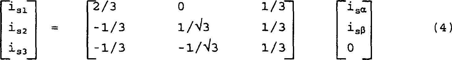
Statorkoordinaten und sich drehenden Feldkoordinaten. Die Statorströme in einem
ausgeglichenen Dreiphasenkoordinatensystem, wie sie durch die Ströme auf den
drei Statorenergieabnehmern

Die Zweiphasenstatorströme isα und isβ können durch die folgende Umwandlung als eine Funktion des Rotorflußwinkels θs in die Feldkoordinatenströme isd und isq umgeformt werden.The two-phase stator currents i sα and i sβ can be converted into the field coordinate currents i sd and i sq by the following conversion as a function of the rotor flux angle θ s .
![]()
![]()
Die Umwandlung von Feldkoordinaten in Zweiphasenkoordinaten wird durch die Umkehrung von Gleichung (2) erreicht, was zu folgendem führt:The Transformation of field coordinates into two-phase coordinates is performed by achieves the inverse of equation (2), resulting in the following:
![]()
![]()
Die Umwandlung von Zweiphasen- zu ausgeglichenen Dreiphasenkoordinaten wird durch Umkehrung von Gleichung (1) erreicht:The Conversion of two-phase to balanced three-phase coordinates is achieved by reversing equation (1):
Darstellungen
des Statorstromvektors im sich drehenden d,q-Feldkoordinatensystem, im stationären Zweiphasen-α,β-Koordinatensystem
und in stationären
ausgeglichenen Dreiphasenkoordinatensystem sind in
Der
Aufbau der Generatorkontrolleinheit
Praktisch
beinhaltet die Generatorkontrolleinheit
Der
Feldausrichtungsumwandler
Der
gewünschte
Rotorfluß λ* r wird durch die folgende Gleichung bestimmt: 
λ•* r = Zeitableitung des gewünschten Rotorflusses
Rr = Rotorwiderstand
Lo =
Gegeninduktivität
Lr = Rotoreigeninduktivität.The desired rotor flux λ * r is determined by the following equation:
λ • * r = time derivative of the desired rotor flux
R r = rotor resistance
L o = mutual inductance
L r = rotor self-inductance.
Im
Normalfall kann die Gleichung (5) durch die folgende Rekursivgleichung
dargestellt werden: 
λ* r(k–1) = λ* r bei Zeit k–1
i* sd(k–1) =
i* sd bei Zeit k
Δt = Abtastzeitperiode
zwischen Zeit k–1
und Zeit k.Normally, equation (5) can be represented by the following recursive equation:
λ * r (k-1) = λ * r at time k-1
i * sd (k-1) = i * sd at time k
Δt = sampling time period between time k-1 and time k.
Wenn
i* sd konstant ist,
ist die Zeitableitung λ•* r = 0, so daß sich die Gleichung (6) auf 
P = Anzahl der Generatorpole
isq = Querachsenstrom.If i * sd is constant, the time derivative λ • * r = 0, so that the equation (6) on
P = number of generator poles
i sq = cross axis current.
Die
Lösung
der Gleichung (8) für
isq liefert den folgenden Ausdruck für den gewünschten
drehmomenterzeugenden Querachsenstrom als eine Funktion des Drehmomentbezugswertes,
der durch die Drehmomentsteuervorrichtung 
Wurden
erst der gewünschte
Rotorkraftfluß λ* r und der gewünschte Querachsenstrom i* sq bestimmt, kann
der gewünschte
Rotorflußwinkel θ* s zu einem bestimmten
Zeitpunkt gefunden werden. Dies wird durch Lösung der folgenden Gleichungen
erreicht: 
ω* s = gewünschte Rotorflußgeschwindigkeit
ωr = tatsächliche
Rotorgeschwindigkeit
θ* s = gewünschter
momentaner Rotorfluß winkel.Once the desired rotor flux λ * r and the desired transverse axis current i * sq have been determined, the desired rotor flux angle θ * s can be found at a particular point in time. This is achieved by solving the following equations:
ω * s = desired rotor flux velocity
ω r = actual rotor speed
θ * s = desired instantaneous rotor flux angle.
Die Maschinenschlupfgeschwindigkeit ω* s1 wird unter Verwendung von Gleichung (10) aus den berechneten Werten des gewünschten Rotorflusses λ* r und des gewünschten Querachsenstroms i* sq erhalten. Die gemessene Rotorgeschwindigkeit ωr wird dann zur Maschinenschlupfgeschwindigkeit ω* s1 hinzugefügt, um gemäß Gleichung (11) die gewünschte Rotorflußgeschwindigkeit ω* s zu erhalten. Die gewünschte Rotorflußgeschwindigkeit ω* s wird dann Modulo 2π integriert, um den gewünschten augenblicklichen Rotorflußwinkel θ* s zu erhalten.The engine slip velocity ω * s1 is obtained using equation (10) from the calculated values of the desired rotor flux λ * r and the desired transverse axis current i * sq . The measured rotor speed ω r is then added to the machine slip speed ω * s1 to obtain the desired rotor flux velocity ω * s according to equation (11). The desired rotor flux velocity ω * s is then integrated modulo 2π to obtain the desired instantaneous rotor flux angle θ * s .
Die
berechneten werte für
die gewünschten
feldausgerichteten Ströme
i* sd und i* sq den Rotorfluß λ* r, die Rotorflußgeschwindigkeit ω* s und den Rotorflußwinkel θ* s sind für die Strom-
und Spannungsregler
Als
Reaktion auf die durch den Feldausrichtungsumwandler
Ein
einfaches Verfahren der Stromkontrolle, ein Deltamodulator-Stromregler,
ist in
Die
Umformung der gewünschten
Ströme
von Drehfeldkoordinaten in stationäre Zweiphasen-α,β-Koordinaten
wird durch Gleichung (3) erreicht, die auf nachstehendes aufgelöst wird:
Die gewünschten Statorströme werden dann unter Verwendung von Gleichung (4) in Dreiphasenkoordinaten umgeformt.The desired stator then become three-phase coordinates using equation (4) reshaped.
Nach
der Umwandlung der gewünschten
Statorströme
von Feldkoordinaten in Dreiphasenkoordinaten vergleicht der Deltamodulator-Stromregler
dann unter Verwendung von Vergleichs- und Halteeinrichtungen
Ein
anderes Verfahren der Stromkontrolle, eines, das einen Verzerrungsindex
auf ein Mindestmaß verringert,
ist in
Die
Verringerung des Verzerrungsindex J auf ein Mindestmaß umfaßt die Bestimmung,
welcher von acht möglichen
Schalterzuständen
der Gleichrichterschalter tatsächliche
Statorströme
erzeugt, deren Wert am nächsten.
zu den gewünschten
Statorströmen
liegt. Ein Weg, um dieses zu erreichen, wird in 
i s = Statorstromvektor.Minimizing the distortion index J involves determining which of eight possible switch states of the rectifier switches produces actual stator currents, the next value thereof. to the desired stator currents. One way to accomplish this is in
i s = stator current vector.
Die Auswertung der Ableitung über ein diskretes Zeitintervall Δt ergibt für die projizierten Ströme:The Evaluation of the derivative over a discrete time interval Δt gives for the projected streams:

Die projizierten Statorströme können so durch Auswertung der Gleichung (18) unter Verwendung des Spannungsvektors, der sich aus diesem Schalterzustand ergeben würde, erhalten werden.The projected stator currents can by evaluating equation (18) using the voltage vector, could result from this switch state, are obtained.
Nachdem
die projizierten Statorströme
erhalten wurden, kann der Verzerrungsindex J durch Gleichung (15)
oder (16) für
jeden möglichen
Schalterzustand berechnet werden. Der Schalterzustand, der den geringsten
Wert für
J ergibt, ist der Ausgang an den Selektor
Während das
oben beschriebene Verfahren einen Schalterzustand definiert, der
den Verzerrungsindex auf ein Mindestmaß verringert, ist ein anderes äquivalentes
Verfahren aufgrund seiner verringerten Gesamtberechnungen vorzuziehen.
Das alternative Verfahren der Berechnung des Schalterzustandes,
der den Verzerrungsindex auf ein Mindestmaß verringert, ist in
v* sβ = gewünschte β-Achsen-Spannung
vsα =
tatsächliche α-Achsen-Spannung
vsβ =
tatsächliche β-Achsen-Spannung.While the method described above defines a switch state that minimizes the distortion index, another equivalent method is preferable because of its reduced overall calculations. The alternative method of calculating the switch state, which reduces the distortion index to a minimum, is in FIG
v * sβ = desired β-axis voltage
v sα = actual α-axis voltage
v sβ = actual β-axis voltage.
Es kann gezeigt werden, daß die Verringerung der Spannungsdifferenzen der Gleichungen (19) und (20) auf ein Mindest maß äquivalent zu einer Verringerung der Stromdifferenzen der Gleichungen (15) und (16) auf ein Mindestmaß ist, da die Verzerrungsindizes nur um konstante oder proportionale Faktoren abweichen. Aufgrund dieser Äquivalenz kontrolliert eine Verringerung des durch die Gleichungen (19) und (20) definierten Verzerrungsindex auf ein Mindestmaß die Statorströme, selbst wenn die gewünschten Ströme zur Auswertung des Verzerrungsindex in gewünschte Spannungen umgewandelt sind.It can be shown that the Reduction of the voltage differences of equations (19) and (20) to a minimum equivalent to a reduction of the current differences of the equations (15) and (16) is to a minimum, because the distortion indices are just about constant or proportional factors differ. Because of this equivalence controls a reduction of the by the equations (19) and (20) defined distortion index to a minimum the stator currents, even if the desired streams converted to desired voltages for evaluation of the distortion index are.
Wie
in 

Anstelle
des Lösens
von Gleichung (19) oder (20) für
jenen möglichen
Schalterzustand werden als nächstes
die gewünschten α- und β-Achsenspannungen
v* sα und v* sβ mit
der begrenzten Anzahl von Spannungsvektoren, die sich aus den acht
möglichen
Schalterzuständen
ergeben könnten,
verglichen. Diese in

Da die Zustände 0 und 7 dieselbe Nullspannung definieren, gibt es sieben mögliche Statorspannungen, die sich aus den acht möglichen Schalterstellungen der aktiven Schaltereinrichtungen des Gleichrichters ergeben könnten.There the conditions 0 and 7 define the same zero voltage, there are seven possible stator voltages, made up of the eight possible ones Switch positions of the active switching devices of the rectifier result could.
Die
Verringerung des Verzerrungsindex auf ein Mindestmaß wird erreicht,
indem herausgefunden wird, welcher Statorspannungsvektor am nächsten am
durch v* sα und
v* sβ definierten gewünschten
Spannungsvektor liegt. Graphisch kann der α,β-Koordinatenraum in sieben Bereiche
geteilt werden, einen Innenkreis
Für die Bestimmung
des am nächsten
liegenden Spannungsvektors wird herausgefunden, in welchen Bereich
der gewünschte
Spannungsvektor fällt.
Dazu wird die Größe des gewünschten
Spannungsvektors zuerst mit vdc/2 verglichen,
um zu bestimmen, ob der gewünschte
Spannungsvektor in den Innenkreis
Übersteigt
die Größenordnung
des gewünschten
Spannungsvektors vdc/2, so werden als nächstes die Vorzeichen
von v* sα und
v* sβ untersucht, um zu bestimmen,
in welchen Quadranten der Spannungsvektor fällt. Ist das Vorzeichen von
v* sα positiv, so sind die
Zustände
1, 2 oder 6 Anwärter,
ist es negativ, die Zustände
3, 4 oder 5. Sind z.B. sowohl v* sα und
v* sβ positiv, ist der am nächsten liegende
Spannungsvektor entweder Zustand 1 oder Zustand 2. Sind v* sα und v* sβ positiv,
so liegt Zustand 1 am nächsten,
wenn v* sα > √3v* sβ ist, ansonsten liegt
Zustand 2 am nächsten.
Dies ist so, weil eine Trennungslinie

Das
Auswählen
zwischen den Zustanden 3 und 4, 4 und 5 und 1 und 6 in den anderen
Quadranten erfolgt auf dieselbe Weise. Ist einmal der am nächsten liegende
Spannungsvektor gefunden, wird, der diesem Spannungsvektor zugehörige Schalterzustand
an den Selektor
Um
wieder auf
Bei
höheren
Geschwindigkeiten jedoch, wo die elektromotorische Kraft sich der
Spannung der Gleichstromspannungsverbindung annähert, können die Statorspannungen nicht
länger
ignoriert werden. In diesem Betriebsbereich zieht der Spannungsregler
Der
Selektor
Wie
der Stromregler
Die
Statorspannungen in Feldkoordinaten sind durch die folgenden Gleichungen
definiert: 
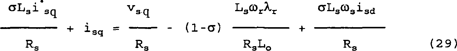
Ls = Statorinduktivität
Rs = Statorwiderstand.The stator voltages in field coordinates are defined by the following equations:
L s = stator inductance
R s = stator resistance.
Die letzten beiden Glieder auf den rechten Seiten der Gleichungen (28) und (29) sind Kopplungsglieder, für die ein Ausgleich erforderlich ist, um eine Kreuzkopplung zwi- schen den direkten und den Querachsen zu beseitigen. Das Ziel ist, v* sd als eine Funktion von i* sd und i* sq als eine Funktion von i* sq zu erzeugen. Eine Beseitigung der Kreuzkopplungsglieder erlaubt es v* sd, den Rotorfluß und v* sq, das Drehmoment zu kontrollieren.The last two terms on the right-hand side of equations (28) and (29) are coupling elements that require compensation to eliminate crosstalk between the direct and transverse axes. The goal is to generate v * sd as a function of i * sd and i * sq as a function of i * sq . Elimination of the cross coupling members allows v * sd to control the rotor flux and v * sq to control the torque.
Der
Arbeitsvorgang des Spannungsreglers
Der Wert von v* sq wird dann durch Addition eines Entkopplungsfaktors, der aus den beiden Spannungskopplungsgliedern auf der rechten Seite der Gleichung (29) besteht, ausgeglichen, was zu v* sq wie folgt führtThe value of v * sq is then equalized by adding a decoupling factor consisting of the two voltage coupling elements on the right side of equation (29), resulting in v * sq as follows

Gleichermaßen wird
die gewünschte
Spannung auf der direkten Achse, v* sd, erzeugt, indem zuerst der durch die Gegeninduktivität geteilte
Rotorfluß, λ* r/Lo, vom gewünschten
Direktachsenstrom i* sd abgezogen
wird. Das Ergebnis wird dann in einen anderen PI-Regler

Sind
die gewünschten
Feldkoordinatenspannungen v* sd und
v* sq erst einmal
erzeugt, werden sie durch die Gleichungen (3) und (4) in Dreiphasenstatorspannungen
umgeformt, was zu v* s1,
v* s2 und v* s3 führt . Diese Bezugsspannungen
werden durch eine Dreiecksträgerwelle
moduliert, um die PWM-Kommutationssignale D1, D1, D2, D2,
D3 und D3 zu erzeugen,
die zum Selektor
Wendet
man sich nun der Inverterseite des Windturbinensystems zu, so sind
die Einzelheiten der Inverterkontrolleinheit
Die Inverterkontrolleinheit kontrolliert die Inverterschaltmatrix, um mit einem regulierbaren Leistungsfaktor und geringem Gesamtklirrfaktor (THD) an das Versorgungsenergieverteilernetz zu liefern. Der Inverter und seine Kontrolleinheit können Blindleistung liefern oder aufnehmen, wie es bei der Regulierung des Phasenunterschieds zwischen der Ausgangsspannung und dem Strom notwendig ist. Ein geringer Gesamtklirrfaktor wird auf dieselbe Weise wie im Stromregler der Generatorkontrolleinheit durch periodische Verringerung eines Verzerrungsindex auf ein Mindestmaß erreicht. Zusätzlich kontrolliert die Inverterkontrolleinheit auch die Spannung der Gleichstromspannungsverbindung, um sie bei einem gewünschten Wert zu halten.The Inverter control unit controls the inverter switching matrix to with an adjustable power factor and low total harmonic distortion (THD) to the supply energy distribution network. The inverter and his control unit can Provide or absorb reactive power, as in regulation the phase difference between the output voltage and the current necessary is. A low total harmonic distortion is on the same As in the current controller of the generator control unit by periodic Reduction of a distortion index to a minimum. additionally the inverter control unit also controls the voltage of the DC voltage connection, to look for you at a desired Value.
Wie
in
Der
Multiplikationsfaktor Iref wird wie folgt
berechnet. Die gemessene Gleichstromverbindungsspannung vdc wird von einem gewünschten Wert der Gleichstromverbindungsspannung
v* dc abgezogen,
um eine Abweichung zu erzeugen, die dann in einen PI-Regler
Die
drehende Umwandlung der Bezugswellenform kann entweder in Dreiphasenkoordinaten
oder in Zweiphasenkoordinaten durchgeführt werden. In Dreiphasenkoordinaten
wird die Musterwellenform, die um einen Winkel ϕ gedreht
ist, wie folgt berechnet: 
Diese
Werte können
unter Verwendung von Gleichung (1) in das Zweiphasen-α,β-Koordinatensystem umgeformt
werden. Das Ergebnis ist vtα und vtβ. Die
Musterwerte vtα und
vtβ,
die sich aus der drehenden Umwandlung ergeben, werden dann mit dem
Wert von Iref multipliziert, um die gewünschten
Zweiphasenausgangsströme
i* oα und i* oβ zu
erzeugen. Die gewünschten
Ausgangsströme
werden in einen Stromregler
Der
Stromregler 
i* oα(k+1) und i* oβ(k+1)
die gewünschten
Ausgangsströme
bei einer Zeit = k+1 in α,β-Koordinaten
sind;
ioα und
ioβ die
gemessen Ausgangsströme
in α,β-Koordinaten sind;
voα und
voβ die
gemessenen Ausgangsspannungen in α,β-Koordinaten
sind; und
Δt
die Abtastperiode ist.The current regulator
i * oα (k + 1) and i * oβ (k + 1) are the desired output currents at a time = k + 1 in α, β coordinates;
i oα and i oβ are the measured output currents in α, β coordinates;
v oα and v oβ are the measured output voltages in α, β coordinates; and
Δt is the sampling period.
Die
gewünschten
Ausgangsspannungen voα und voβ werden
dann mit den sieben verfügbaren
Spannungsvektoren verglichen und der dem nächsten Spannungsvektor zugehörige Schalterzustand
ausgewählt und
an die Inverterschalter ausgegeben. Die Bestimmung des nächsten Spannungsvektors
erfolgt auf dieselbe weise wie oben unter Bezugnahme auf den Generatorstromregler
von
Ein
Computerprogramm lenkt den Betrieb des Digitalsignalprozessors der
Inverterkontrolleinheit, um die oben beschriebenen Berechnungen
auszuführen.
Wie in
Unter
erneuter Bezugnahme auf
Die Leistungsfaktorkorrektureinrichtung der Inverterkontrolleinheit kann durch Betrieb in einer statischen VAR-Betriebsart sogar dann verwendet werden, wenn die Windturbine nicht arbeitet. Dazu setzt der Leistungsfaktorregler den Leistungsfaktorwinkel ϕ gleich 90°. Nachdem die Gleichstromverbindung durch das Versorgungsnetz über den Inverter aufgeladen wurde, arbeitet die Inverterkontrolleinheit wie oben beschrieben, um den Ausgangsstrom zur Führung der Spannung bei 90° zu drehen. Dies liefert Blindleistung an das Versorgungsnetz, um Blindlasten, die Leistung vom Versorgungsnetz abziehen, entgegenzuwirken.The power factor correction means of the inverter control unit can be used by operating in a static VAR mode even when the wind turbine is not operating. To do this, the power factor controller sets the power factor angle φ equal to 90 °. After the DC connection is charged through the supply network via the inverter, the inverter control unit operates as described above to turn the output current to drive the voltage at 90 °. This provides reactive power to the utility grid to counteract reactive loads that drain power from the utility grid.
Aus der obigen Beschreibung wird deutlich, daß die hierin offenbarte Erfindung eine neue und vorteilhafte Windturbine mit variabler Geschwindigkeit schafft. Die vorhergehende Besprechung offenbart und beschreibt nur beispielhafte Verfahren und Ausführungen der vorliegenden Erfindung. Es versteht sich für Fachleute von selbst, daß die Erfindung in anderen bestimmten Formen ausgeführt werden kann, ohne von den wesentlichen Merkmalen davon abzuweichen. Zum Beispiel können manche Gesichtspunkte des Stromreglers auf verschiedenste Arten ausgeführt werden, die den offenbarten gleichwertig sind, was Hysteresekontrolle oder erzwungene Schwingungen mit Dreiecksschnittpunkt beinhaltet. Der Generator muß kein Dreiphasen-Käfigläufergenerator sein, son dern kann jedweder Mehrphasengenerator sein, was einen Synchrongenerator beinhaltet. Bestimmte Gesichtspunkte der Generatorkontrolle können anstelle der hier offenbarten geschlossenen Schleife mit offener Schleife ausgeführt werden. Der Energieumwandler könnte eine Gleichstromstromverbindung aufweisen oder ein Zykloumformer anstelle einer Gleichstromspannungsverbindung sein. Außerdem könnte der Drehmomentmonitor das Drehmoment mit einem Übertragungssystem direkt messen, anstelle das Drehmoment von den gemessenen Statorströmen abzuleiten. Demgemäß soll die Offenbarung der vorliegenden Erfindung den Umfang der Erfindung, der in den nachfolgenden Ansprüchen aufgezeigt wird, veranschaulichen, aber nicht beschränken.Out It will be apparent from the foregoing description that the invention disclosed herein a new and advantageous wind turbine with variable speed creates. The previous discussion discloses and describes only exemplary methods and embodiments of the present invention. It goes without saying Professionals by themselves that the Invention can be carried out in other specific forms without departing from the essential Deviate from it. For example, some aspects of the current controller are carried out in various ways, which disclosed the equivalent to what hysteresis control or forced oscillations includes with triangle intersection. The generator does not need a three phase squirrel cage generator son, can be any polyphase generator, what a Synchronous generator includes. Certain aspects of generator control can instead of the closed loop disclosed herein Loop executed become. The energy converter could have a DC power connection or a cycloconverter instead of a DC voltage connection. In addition, the Torque monitor directly measure the torque with a transmission system, instead of deriving the torque from the measured stator currents. Accordingly, the Disclosure of the present invention the scope of the invention, in the following claims is illustrated, illustrated but not limited.
Claims (35)
Applications Claiming Priority (2)
| Application Number | Priority Date | Filing Date | Title |
|---|---|---|---|
| US07649567 US5083039B1 (en) | 1991-02-01 | 1991-02-01 | Variable speed wind turbine |
| US649567 | 2003-08-27 |
Publications (2)
| Publication Number | Publication Date |
|---|---|
| DE69233343D1 DE69233343D1 (en) | 2004-05-13 |
| DE69233343T2 true DE69233343T2 (en) | 2005-03-17 |
Family
ID=24605356
Family Applications (3)
| Application Number | Title | Priority Date | Filing Date |
|---|---|---|---|
| DE9219171U Expired - Lifetime DE9219171U1 (en) | 1991-02-01 | 1992-01-31 | Variable speed wind turbine |
| DE69233343T Expired - Lifetime DE69233343T2 (en) | 1991-02-01 | 1992-01-31 | Wind turbine with variable speed |
| DE69228053T Revoked DE69228053T2 (en) | 1991-02-01 | 1992-01-31 | WIND TURBINE WITH VARIABLE SPEED |
Family Applications Before (1)
| Application Number | Title | Priority Date | Filing Date |
|---|---|---|---|
| DE9219171U Expired - Lifetime DE9219171U1 (en) | 1991-02-01 | 1992-01-31 | Variable speed wind turbine |
Family Applications After (1)
| Application Number | Title | Priority Date | Filing Date |
|---|---|---|---|
| DE69228053T Revoked DE69228053T2 (en) | 1991-02-01 | 1992-01-31 | WIND TURBINE WITH VARIABLE SPEED |
Country Status (9)
| Country | Link |
|---|---|
| US (2) | US5083039B1 (en) |
| EP (3) | EP0884833B1 (en) |
| JP (1) | JP3435474B2 (en) |
| AU (1) | AU1554292A (en) |
| CA (1) | CA2100672C (en) |
| DE (3) | DE9219171U1 (en) |
| DK (2) | DK0884833T3 (en) |
| ES (2) | ES2219807T3 (en) |
| WO (1) | WO1992014298A1 (en) |
Families Citing this family (473)
| Publication number | Priority date | Publication date | Assignee | Title |
|---|---|---|---|---|
| US5483435A (en) * | 1989-05-15 | 1996-01-09 | Kabushiki Kaisha Toshiba | Power generation system having induction generator and controlled bridge rectifier |
| US5083039B1 (en) * | 1991-02-01 | 1999-11-16 | Zond Energy Systems Inc | Variable speed wind turbine |
| US5155375A (en) * | 1991-09-19 | 1992-10-13 | U.S. Windpower, Inc. | Speed control system for a variable speed wind turbine |
| WO1993011604A1 (en) * | 1991-11-27 | 1993-06-10 | U.S. Windpower, Inc. | Variable speed wind turbine with reduced power fluctuation and a static var mode of operation |
| WO1994004819A1 (en) * | 1992-08-18 | 1994-03-03 | Four Winds Energy Corporation | Wind turbine particularly suited for high-wind conditions |
| US5289042A (en) * | 1992-12-11 | 1994-02-22 | Edward Lis | Wind operated generator |
| JPH06261454A (en) * | 1993-03-09 | 1994-09-16 | Hitachi Ltd | Starting equipment for power generating facilities |
| EP0652633B1 (en) * | 1993-11-09 | 1999-10-13 | Kabushiki Kaisha Toshiba | Power conversion system and control device therefor |
| US5663631A (en) * | 1994-07-19 | 1997-09-02 | Nippondenso Co., Ltd. | Generator with circuitry for controlling power generation based on rotational speed |
| JPH0835712A (en) * | 1994-07-26 | 1996-02-06 | Fujitsu General Ltd | Controller for air conditioner |
| US5900722A (en) * | 1994-09-14 | 1999-05-04 | Coleman Powermate, Inc. | Multimode power converter |
| FR2725852B1 (en) * | 1994-10-14 | 1997-01-03 | Europ Gas Turbines Sa | ELECTRIC POWER GENERATOR PROVIDED WITH FREQUENCY ADAPTATION DEVICES |
| DE69530828T2 (en) * | 1994-12-16 | 2004-01-22 | Delphi Technologies, Inc., Troy | Torque and output control of an internal combustion engine |
| US5663600A (en) * | 1995-03-03 | 1997-09-02 | General Electric Company | Variable speed wind turbine with radially oriented gear drive |
| GB9508051D0 (en) * | 1995-04-20 | 1995-06-07 | Switched Reluctance Drives Ltd | Compensation for input voltage variation in an electric motor drive |
| JP3675014B2 (en) * | 1995-06-08 | 2005-07-27 | 株式会社デンソー | Inverter control device |
| WO1997004521A1 (en) * | 1995-07-18 | 1997-02-06 | Midwest Research Institute | A variable speed wind turbine generator system with zero-sequence filter |
| GB2304208B (en) * | 1995-08-07 | 1999-06-23 | Baylis Generators Ltd | Generator |
| US5726560A (en) * | 1995-09-01 | 1998-03-10 | Barber-Colman Company | Switched reluctance generator |
| JPH0984400A (en) * | 1995-09-14 | 1997-03-28 | Fanuc Ltd | Method for controlling current of servomotor |
| US5899411A (en) * | 1996-01-22 | 1999-05-04 | Sundstrand Corporation | Aircraft electrical system providing emergency power and electric starting of propulsion engines |
| DE19635960C2 (en) * | 1996-09-05 | 2003-04-10 | Aerodyn Eng Gmbh | Method for connecting a wind turbine to the grid |
| US6177735B1 (en) | 1996-10-30 | 2001-01-23 | Jamie C. Chapman | Integrated rotor-generator |
| DK174291B1 (en) * | 1997-06-26 | 2002-11-18 | Mita Teknik As | Method for connecting an asynchronous generator to an AC power supply and an electrical coupling for use in this method |
| US6600240B2 (en) * | 1997-08-08 | 2003-07-29 | General Electric Company | Variable speed wind turbine generator |
| AU774980B2 (en) * | 1997-08-08 | 2004-07-15 | General Electric Company | Variable speed wind turbine generator |
| AU2004220762B2 (en) * | 1997-08-08 | 2007-11-22 | General Electric Company | Variable speed wind turbine generator |
| US6137187A (en) * | 1997-08-08 | 2000-10-24 | Zond Energy Systems, Inc. | Variable speed wind turbine generator |
| US6420795B1 (en) * | 1998-08-08 | 2002-07-16 | Zond Energy Systems, Inc. | Variable speed wind turbine generator |
| IES78624B2 (en) * | 1997-10-07 | 1998-02-25 | Gineadoiri Gaoithe Teicneolaio | A wind energy system |
| DE19756777B4 (en) * | 1997-12-19 | 2005-07-21 | Wobben, Aloys, Dipl.-Ing. | Method for operating a wind energy plant and wind energy plant |
| US6300689B1 (en) * | 1998-05-04 | 2001-10-09 | Ocean Power Technologies, Inc | Electric power generating system |
| NL1009543C2 (en) * | 1998-07-02 | 2000-01-07 | Lagerwey Windturbine B V | Device for converting wind energy into electrical energy. |
| US6128204A (en) * | 1998-08-26 | 2000-10-03 | Northrop Grumman Corporation | Line power unit for micropower generation |
| US6072302A (en) | 1998-08-26 | 2000-06-06 | Northrop Grumman Corporation | Integrated control system and method for controlling mode, synchronization, power factor, and utility outage ride-through for micropower generation systems |
| DE19844050A1 (en) * | 1998-09-25 | 2000-03-30 | Abb Daimler Benz Transp | Open and closed loop control method for electrical drive involving induction motor with voltage measured at output of sine wave filter in which complex vector is assigned in rotating reference system |
| US6617705B1 (en) * | 1998-10-28 | 2003-09-09 | Ocean Power Technologies, Inc. | Protection arrangement for natural energy power generation systems |
| US6448669B1 (en) | 1998-12-01 | 2002-09-10 | Dillyn M. Elder | Water power generation system |
| US6191496B1 (en) | 1998-12-01 | 2001-02-20 | Dillyn M. Elder | Wind turbine system |
| JP3578930B2 (en) * | 1999-01-13 | 2004-10-20 | 本田技研工業株式会社 | Generators and generator equipment |
| DE10020635A1 (en) | 1999-09-13 | 2001-03-15 | Aloys Wobben | Process for controlling reactive power and device for generating electrical energy in an electrical network |
| EP1224721B1 (en) * | 1999-09-13 | 2005-09-28 | Aloys Wobben | Method for controlling the reactive power and device for generating electrical energy in an electrical network |
| DK199901436A (en) * | 1999-10-07 | 2001-04-08 | Vestas Wind System As | Wind turbine |
| US6362540B1 (en) | 1999-10-20 | 2002-03-26 | Pinnacle West Capital Corporation | Expandable hybrid electric generator and method therefor |
| DE19953238A1 (en) * | 1999-11-04 | 2001-05-17 | Gunther Duensing | Electrical power supply method involves parallel mode with isolated network coupled to public network via protective device that is opened if public network fails to select isolated mode |
| GB9928843D0 (en) * | 1999-12-06 | 2000-02-02 | Lucas Industries Ltd | Switched reluctance generator and a method of controlling such a generator |
| FR2804254B1 (en) * | 2000-01-26 | 2002-05-31 | Air Liquide | IMPROVED METHOD FOR PROVIDING ELECTRIC POWER TO THE NETWORK USING AN AC GENERATOR ASSOCIATED WITH A TURBINE |
| ES2333199T3 (en) * | 2000-01-28 | 2010-02-18 | Cummins Generator Technologies Limited | AC POWER GENERATOR SYSTEM. |
| DE20001864U1 (en) * | 2000-02-03 | 2000-04-20 | Siemens AG, 80333 München | Wind turbine group with at least two wind turbines |
| JP3352662B2 (en) * | 2000-02-03 | 2002-12-03 | 関西電力株式会社 | Power system stabilizing apparatus and power system stabilizing method using secondary battery system |
| EP1126163A1 (en) * | 2000-02-16 | 2001-08-22 | Turbowinds N.V./S.A. | Blade pitch angle control device for wind turbine |
| DE10011393A1 (en) * | 2000-03-09 | 2001-09-13 | Tacke Windenergie Gmbh | Control system for a wind turbine |
| DE10011929B4 (en) * | 2000-03-11 | 2004-07-01 | Wobben, Aloys, Dipl.-Ing. | synchronous generator |
| DE10016912C1 (en) * | 2000-04-05 | 2001-12-13 | Aerodyn Eng Gmbh | Operation of offshore wind turbines dependent on the natural frequency of the tower |
| SE0001611L (en) * | 2000-05-03 | 2001-11-04 | Abb Ab | Power plant and method of operation thereof |
| DE10022974C2 (en) * | 2000-05-11 | 2003-10-23 | Aloys Wobben | Method for operating a wind energy plant and wind energy plant |
| EP1284045A1 (en) * | 2000-05-23 | 2003-02-19 | Vestas Wind System A/S | Variable speed wind turbine having a matrix converter |
| ES2165324B2 (en) * | 2000-06-02 | 2004-01-16 | Internat Electronics S A | POWER AND CONTROL SYSTEM TO IMPROVE THE PERFORMANCE AND QUALITY OF ENERGY PRODUCED IN AEROGENERATORS. |
| US6518736B2 (en) * | 2000-06-26 | 2003-02-11 | Toyota Jidosha Kabushiki Kaisha | Mechanical power outputting apparatus and inverter apparatus |
| DE10033183C2 (en) * | 2000-07-07 | 2002-08-08 | Max Planck Gesellschaft | Method and device for processing and predicting flow parameters of turbulent media |
| US6653744B2 (en) * | 2000-08-01 | 2003-11-25 | Clipper Wind Technology, Inc. | Distributed generation drivetrain (DGD) controller for application to wind turbine and ocean current turbine generators |
| US6731019B2 (en) * | 2000-08-07 | 2004-05-04 | Ocean Power Technologies, Inc. | Apparatus and method for optimizing the power transfer produced by a wave energy converter (WEC) |
| DE10040273A1 (en) * | 2000-08-14 | 2002-02-28 | Aloys Wobben | Wind turbine |
| US20020024828A1 (en) * | 2000-08-31 | 2002-02-28 | Hidetake Hayashi | Inverter suitable for use with portable AC power supply unit |
| US6239997B1 (en) | 2000-09-01 | 2001-05-29 | Ford Motor Company | System for connecting and synchronizing a supplemental power source to a power grid |
| US20020036430A1 (en) * | 2000-09-28 | 2002-03-28 | Welches Richard S. | Local area grid for distributed power |
| US6608397B2 (en) * | 2000-11-09 | 2003-08-19 | Ntn Corporation | Wind driven electrical power generating apparatus |
| DE10059018C2 (en) * | 2000-11-28 | 2002-10-24 | Aloys Wobben | Wind turbine or wind farm consisting of a large number of wind turbines |
| DE10063654B4 (en) * | 2000-12-20 | 2008-07-17 | Nucellsys Gmbh | Method and arrangement for generating accelerator position-dependent current values for the power control of one or more drives in a mobile device with a fuel cell for the power supply |
| US20020084655A1 (en) * | 2000-12-29 | 2002-07-04 | Abb Research Ltd. | System, method and computer program product for enhancing commercial value of electrical power produced from a renewable energy power production facility |
| WO2002065611A1 (en) * | 2001-02-16 | 2002-08-22 | Yanmar Co., Ltd. | Power system having generator driven by engine |
| FR2821391B1 (en) * | 2001-02-23 | 2003-06-27 | Jeumont Ind | METHOD AND DEVICE FOR CONTROLLING AN ELECTRIC POWER GENERATION INSTALLATION COMPRISING A WIND TURBINE |
| JP3873634B2 (en) * | 2001-02-28 | 2007-01-24 | 株式会社日立製作所 | Wind power generation system |
| DE10109553B4 (en) * | 2001-02-28 | 2006-03-30 | Wobben, Aloys, Dipl.-Ing. | Air density dependent power control |
| DE10117212A1 (en) * | 2001-04-06 | 2002-10-10 | Dewind Ag | Method for operating a wind turbine |
| BR0209005A (en) * | 2001-04-20 | 2004-08-10 | Aloys Wobben | Process for operating a wind power installation, and, wind power installation |
| DE10119624A1 (en) * | 2001-04-20 | 2002-11-21 | Aloys Wobben | Operating wind energy plant involves regulating power delivered from generator to electrical load, especially of electrical network, depending on current delivered to the load |
| DE10136974A1 (en) * | 2001-04-24 | 2002-11-21 | Aloys Wobben | Method for operating a wind turbine |
| US6670721B2 (en) * | 2001-07-10 | 2003-12-30 | Abb Ab | System, method, rotating machine and computer program product for enhancing electric power produced by renewable facilities |
| DE10134883A1 (en) * | 2001-07-18 | 2003-01-30 | Abb Research Ltd | Method and device for speed-adjustable power electronic control of a gearless wind turbine |
| US6492801B1 (en) | 2001-08-21 | 2002-12-10 | Southern Company Services, Inc. | Method, apparatus, and system for real time reactive power output monitoring and predicting |
| US6661113B1 (en) | 2001-08-31 | 2003-12-09 | Walter E. Bonin | Power generator |
| EP3032685A1 (en) * | 2001-09-28 | 2016-06-15 | Wobben Properties GmbH | Method for operating a wind farm |
| US6703718B2 (en) * | 2001-10-12 | 2004-03-09 | David Gregory Calley | Wind turbine controller |
| US6836028B2 (en) * | 2001-10-29 | 2004-12-28 | Frontier Engineer Products | Segmented arc generator |
| DE10153644C2 (en) * | 2001-10-31 | 2003-11-20 | Aloys Wobben | Wind turbine with contactless energy transfer to the rotor |
| GB0128590D0 (en) * | 2001-11-29 | 2002-01-23 | Engineering Business Ltd | Electricity generators |
| GB0128662D0 (en) * | 2001-11-30 | 2002-01-23 | Rolls Royce Plc | Improvements in or relating to generator arrangements |
| US7773614B1 (en) * | 2001-12-05 | 2010-08-10 | Adaptix, Inc. | Wireless communication subsystem with a digital interface |
| US20040080165A1 (en) * | 2001-12-31 | 2004-04-29 | Capstone Turbine Corporation | Turbogenerator/motor controller with ancillary energy storage/discharge |
| JP4023171B2 (en) * | 2002-02-05 | 2007-12-19 | トヨタ自動車株式会社 | LOAD DRIVE DEVICE, CHARGE CONTROL METHOD FOR POWER STORAGE DEVICE IN LOAD DRIVE DEVICE, AND COMPUTER-READABLE RECORDING MEDIUM CONTAINING PROGRAM FOR CAUSING COMPUTER TO EXECUTE CHARGE CONTROL |
| US7015595B2 (en) * | 2002-02-11 | 2006-03-21 | Vestas Wind Systems A/S | Variable speed wind turbine having a passive grid side rectifier with scalar power control and dependent pitch control |
| JP3970083B2 (en) * | 2002-04-23 | 2007-09-05 | 住友電気工業株式会社 | Operation method of redox flow battery system |
| JPWO2003092110A1 (en) * | 2002-04-23 | 2005-09-02 | 住友電気工業株式会社 | Redox flow battery system design method |
| US6919650B2 (en) * | 2002-05-31 | 2005-07-19 | Ballard Power Systems Corporation | Hybrid synchronization phase angle generation method |
| US7071579B2 (en) * | 2002-06-07 | 2006-07-04 | Global Energyconcepts,Llc | Wind farm electrical system |
| DE10232423A1 (en) * | 2002-07-17 | 2004-01-29 | Ge Wind Energy Gmbh | Method for operating a wind energy installation and wind energy installation for executing such a method |
| JP4135420B2 (en) * | 2002-07-19 | 2008-08-20 | 株式会社明電舎 | Wind power generator output power smoothing control device |
| US20050269822A1 (en) * | 2002-07-24 | 2005-12-08 | Shiro Kinpara | Wind power generator and method for consturcting wind power generator |
| ATE490591T1 (en) * | 2002-09-10 | 2010-12-15 | Dewind Co | OPERATING METHOD FOR WIND TURBINE WITH OVERSYNCHRONOUS CASCADE |
| US6787259B2 (en) * | 2002-09-12 | 2004-09-07 | Metallic Power, Inc. | Secondary power source for use in a back-up power system |
| AU2002368205A1 (en) * | 2002-09-13 | 2004-04-30 | Abb Ab | Wind power fed network |
| US6879053B1 (en) * | 2002-10-22 | 2005-04-12 | Youtility, Inc. | Transformerless, load adaptive speed controller |
| AU2003282994A1 (en) * | 2002-10-22 | 2004-05-13 | Youtility, Inc. | Hybrid variable speed generator/uninterruptible power supply power converter |
| WO2004040748A1 (en) * | 2002-11-01 | 2004-05-13 | Vestas Wind Systems A/S | Circuit arrangement for use in a variable speed wind turbine system comprising a double-fed induction generator and a back-to-back converter |
| JP4168252B2 (en) * | 2002-12-27 | 2008-10-22 | 株式会社安川電機 | Power generation system and control method thereof |
| DE10300174B3 (en) * | 2003-01-08 | 2004-12-23 | Nordex Energy Gmbh | Wind turbine with at least two components and a data network |
| US6984897B2 (en) * | 2003-01-23 | 2006-01-10 | Spellman High Voltage Electronics Corporation | Electro-mechanical energy conversion system having a permanent magnet machine with stator, resonant transfer link and energy converter controls |
| US6921985B2 (en) * | 2003-01-24 | 2005-07-26 | General Electric Company | Low voltage ride through for wind turbine generators |
| SE524670C2 (en) * | 2003-01-30 | 2004-09-14 | Abb Ab | A power balancing device and method |
| US6888262B2 (en) * | 2003-02-03 | 2005-05-03 | General Electric Company | Method and apparatus for wind turbine rotor load control |
| US7004724B2 (en) * | 2003-02-03 | 2006-02-28 | General Electric Company | Method and apparatus for wind turbine rotor load control based on shaft radial displacement |
| US7322794B2 (en) * | 2003-02-03 | 2008-01-29 | General Electric Company | Method and apparatus for condition-based monitoring of wind turbine components |
| US7160083B2 (en) * | 2003-02-03 | 2007-01-09 | General Electric Company | Method and apparatus for wind turbine rotor load control |
| WO2004083630A2 (en) * | 2003-03-21 | 2004-09-30 | Vestas Wind Systems A/S | Methods of moving the rotating means of a wind turbine during transportation or stand still, method of controlling the moving of the rotating means, nacelle, auxiliary device, control and monitoring system and use hereof |
| WO2004088815A1 (en) * | 2003-03-31 | 2004-10-14 | Mayekawa Mfg. Co., Ltd. | Coal energy utilization system by superconducting power transmission |
| EP1467094B2 (en) * | 2003-04-08 | 2017-03-01 | GE Energy Power Conversion GmbH | A wind turbine for producing electrical power and a method of operating the same |
| US6940185B2 (en) * | 2003-04-10 | 2005-09-06 | Advantek Llc | Advanced aerodynamic control system for a high output wind turbine |
| US7042110B2 (en) * | 2003-05-07 | 2006-05-09 | Clipper Windpower Technology, Inc. | Variable speed distributed drive train wind turbine system |
| FI115874B (en) * | 2003-05-27 | 2005-07-29 | Abb Oy | A method for adjusting a double-feed machine |
| DE10327344A1 (en) * | 2003-06-16 | 2005-01-27 | Repower Systems Ag | Wind turbine |
| DE10330473A1 (en) * | 2003-07-05 | 2005-01-27 | Alstom Technology Ltd | Frequency converter for high-speed generators |
| DE10336068B4 (en) * | 2003-08-06 | 2006-04-06 | Siemens Ag | Method for the controlled imprinting of a stator current and a torque setpoint for a converter-fed induction machine |
| DE10338127C5 (en) * | 2003-08-15 | 2015-08-06 | Senvion Se | Wind turbine with a rotor |
| US6924565B2 (en) * | 2003-08-18 | 2005-08-02 | General Electric Company | Continuous reactive power support for wind turbine generators |
| US8560476B2 (en) * | 2003-08-26 | 2013-10-15 | The Trustees Of Columbia University In The City Of New York | Martingale control of production for optimal profitability of oil and gas fields |
| DE10341504A1 (en) * | 2003-09-03 | 2005-06-09 | Repower Systems Ag | Method for operating a wind turbine, wind turbine and method for providing control power with wind turbines |
| US7119452B2 (en) * | 2003-09-03 | 2006-10-10 | General Electric Company | Voltage control for wind generators |
| EP1665494B2 (en) | 2003-09-03 | 2023-06-28 | Siemens Gamesa Renewable Energy Service GmbH | Method for operating or controlling a wind turbine and method for providing primary control power by means of wind turbines |
| US6981839B2 (en) * | 2004-03-09 | 2006-01-03 | Leon Fan | Wind powered turbine in a tunnel |
| CN100379113C (en) * | 2003-09-11 | 2008-04-02 | 上海交通大学 | Integrated method for realizing parallel operation power generation and power network reactive power compensation simultaneously |
| DE10344392A1 (en) * | 2003-09-25 | 2005-06-02 | Repower Systems Ag | Wind turbine with a reactive power module for grid support and method |
| JP4269941B2 (en) * | 2004-01-08 | 2009-05-27 | 株式会社日立製作所 | Wind power generator and control method thereof |
| JP4155196B2 (en) * | 2004-01-13 | 2008-09-24 | 株式会社日立製作所 | Rotating electrical machine control device and power generation system |
| US8277964B2 (en) | 2004-01-15 | 2012-10-02 | Jd Holding Inc. | System and method for optimizing efficiency and power output from a vanadium redox battery energy storage system |
| US7265456B2 (en) * | 2004-01-15 | 2007-09-04 | Vrb Bower Systems Inc. | Power generation system incorporating a vanadium redox battery and a direct current wind turbine generator |
| KR20070026362A (en) * | 2004-02-27 | 2007-03-08 | 미츠비시 쥬고교 가부시키가이샤 | Wind turbine generator, active vibration damping method for the same, and wind turbine tower |
| US7605487B2 (en) * | 2004-03-12 | 2009-10-20 | General Electric Company | Method for operating a frequency converter of a generator and wind energy turbine having a generator operated according to the method |
| DE102004013131A1 (en) * | 2004-03-17 | 2005-10-06 | Siemens Ag | Wind turbine |
| ITMI20040778A1 (en) * | 2004-04-21 | 2004-07-21 | Trimmer S A | DOUBLE USER WIND GENERATOR |
| US7038330B2 (en) * | 2004-04-23 | 2006-05-02 | Rwe Piller Gmbh | Protection for wind power station |
| US7148652B2 (en) * | 2004-04-30 | 2006-12-12 | Ace-Tronics Company, Inc. | Method and apparatus for determining and handling brake failures in open loop variable frequency drive motors |
| US7248946B2 (en) * | 2004-05-11 | 2007-07-24 | Advanced Energy Conversion, Llc | Inverter control methodology for distributed generation sources connected to a utility grid |
| DE102004024563B4 (en) * | 2004-05-18 | 2008-01-10 | Nordex Energy Gmbh | Method for generating emergency power for a wind turbine with an auxiliary generator |
| EP1781945A2 (en) * | 2004-06-23 | 2007-05-09 | Energy & Engine Technology Corporation | Method and system for power generation |
| US7095129B2 (en) * | 2004-06-30 | 2006-08-22 | General Electric Company | Methods and apparatus for rotor load control in wind turbines |
| US7175389B2 (en) * | 2004-06-30 | 2007-02-13 | General Electric Company | Methods and apparatus for reducing peak wind turbine loads |
| JP3918837B2 (en) | 2004-08-06 | 2007-05-23 | 株式会社日立製作所 | Wind power generator |
| FI118027B (en) | 2004-08-11 | 2007-05-31 | Abb Oy | Method in connection with a wind turbine |
| US7081696B2 (en) * | 2004-08-12 | 2006-07-25 | Exro Technologies Inc. | Polyphasic multi-coil generator |
| FI119579B (en) * | 2004-08-13 | 2008-12-31 | Abb Oy | Method in Voltage Intermediate Drive and Frequency Converter |
| KR101070906B1 (en) * | 2004-10-01 | 2011-10-06 | 설승기 | Distributed power generation system and control method for the same |
| US7980825B2 (en) * | 2005-10-18 | 2011-07-19 | Robert A. Vanderhye | Savonius rotor blade construction particularly for a three bladed savonius rotor |
| JP4449775B2 (en) * | 2005-02-17 | 2010-04-14 | 株式会社日立製作所 | Secondary excitation power converter |
| US7215035B2 (en) * | 2005-02-22 | 2007-05-08 | Xantrex Technology, Inc. | Method and apparatus for converting wind generated electricity to constant frequency electricity for a utility grid |
| US7126236B2 (en) * | 2005-03-15 | 2006-10-24 | General Electric Company | Methods and apparatus for pitch control power conversion |
| KR100704482B1 (en) * | 2005-04-01 | 2007-04-09 | 엘지전자 주식회사 | A switched reluctance generator with enhanced generating efficiency at low and high speed |
| US7314346B2 (en) * | 2005-11-03 | 2008-01-01 | Vanderhye Robert A | Three bladed Savonius rotor |
| ES2428390T3 (en) * | 2005-05-13 | 2013-11-07 | Siemens Aktiengesellschaft | Power control system of a wind farm |
| GB0510066D0 (en) | 2005-05-17 | 2005-06-22 | Goodrich Control Sys Ltd | A controller for a permanent magnet generator and a generator in combination with such a controller |
| US8649911B2 (en) * | 2005-06-03 | 2014-02-11 | General Electric Company | System and method for operating a wind farm under high wind speed conditions |
| US9306473B2 (en) * | 2005-07-01 | 2016-04-05 | Vestas Wind Systems A/S | Variable rotor speed wind turbine, wind park, method of transmitting electric power and method of servicing or inspecting a variable rotor speed wind turbine |
| US7573160B2 (en) * | 2005-07-20 | 2009-08-11 | General Electric Company | Methods and apparatus for controlling windfarms and windfarms controlled thereby |
| US7476985B2 (en) * | 2005-07-22 | 2009-01-13 | Gamesa Innovation & Technology, S.L. | Method of operating a wind turbine |
| JP4561518B2 (en) * | 2005-07-27 | 2010-10-13 | 株式会社日立製作所 | A power generation apparatus using an AC excitation synchronous generator and a control method thereof. |
| US7239036B2 (en) * | 2005-07-29 | 2007-07-03 | General Electric Company | System and method for power control in wind turbines |
| ES2416288T3 (en) * | 2005-08-12 | 2013-07-31 | General Electric Company | Wind turbine for overvoltage protection |
| US8462889B2 (en) | 2005-10-04 | 2013-06-11 | Hypres, Inc. | Oversampling digital receiver for radio-frequency signals |
| US7923965B2 (en) * | 2005-10-10 | 2011-04-12 | General Electric Company | Methods for coupling an energy storage system to a variable energy supply system |
| US7233079B1 (en) * | 2005-10-18 | 2007-06-19 | Willard Cooper | Renewable energy electric power generating system |
| JP4575272B2 (en) | 2005-10-27 | 2010-11-04 | 株式会社日立製作所 | Distributed power system and system stabilization method |
| US20070100506A1 (en) * | 2005-10-31 | 2007-05-03 | Ralph Teichmann | System and method for controlling power flow of electric power generation system |
| US7511385B2 (en) * | 2005-11-11 | 2009-03-31 | Converteam Ltd | Power converters |
| GB0523087D0 (en) * | 2005-11-11 | 2005-12-21 | Alstom Power Conversion Ltd | Power converters |
| US7345373B2 (en) * | 2005-11-29 | 2008-03-18 | General Electric Company | System and method for utility and wind turbine control |
| US7446435B2 (en) | 2005-11-30 | 2008-11-04 | General Electric Company | Power converter system and method |
| US7319307B2 (en) * | 2005-12-16 | 2008-01-15 | General Electric Company | Power balancing of multiple synchronized generators |
| CN101600882A (en) * | 2006-01-20 | 2009-12-09 | 西南风力公司 | The stall controller of wind turbine and the control gear of trigger condition |
| US7423412B2 (en) * | 2006-01-31 | 2008-09-09 | General Electric Company | Method, apparatus and computer program product for injecting current |
| US7649274B2 (en) * | 2006-02-09 | 2010-01-19 | Windera Power Systems, Inc. | Turbine with constant voltage and frequency output |
| US7352075B2 (en) * | 2006-03-06 | 2008-04-01 | General Electric Company | Methods and apparatus for controlling rotational speed of a rotor |
| EP1835293B1 (en) * | 2006-03-15 | 2010-06-30 | Siemens Aktiengesellschaft | Wind turbine and method of determining at least one rotation parameter of a wind turbine rotor |
| US7508089B2 (en) * | 2006-03-16 | 2009-03-24 | International Components Corporation | Over speed control circuit for a wind turbine generator which maximizes the power exported from the generator over time |
| US7816801B2 (en) | 2006-03-16 | 2010-10-19 | International Components Corporation, Inc. | Speed sensing circuit for a wind turbine generator |
| US7425771B2 (en) * | 2006-03-17 | 2008-09-16 | Ingeteam S.A. | Variable speed wind turbine having an exciter machine and a power converter not connected to the grid |
| CN101401294B (en) * | 2006-03-17 | 2013-04-17 | 英捷电力技术有限公司 | Variable speed wind turbine having an exciter machine and a power converter not connected to the grid |
| US7355294B2 (en) * | 2006-05-22 | 2008-04-08 | General Electric Company | Method and system for wind turbine blade movement |
| US7919879B2 (en) * | 2006-05-31 | 2011-04-05 | Wisconsin Alumni Research Foundation | Power conditioning architecture for a wind turbine |
| US7218012B1 (en) * | 2006-05-31 | 2007-05-15 | General Electric Company | Emergency pitch drive power supply |
| US7586216B2 (en) * | 2006-06-02 | 2009-09-08 | General Electric Company | Redundant electrical brake and protection system for electric generators |
| CN102647058A (en) | 2006-06-08 | 2012-08-22 | Exro技术公司 | Power equipment |
| US7312537B1 (en) * | 2006-06-19 | 2007-12-25 | General Electric Company | Methods and apparatus for supplying and/or absorbing reactive power |
| JP2008011607A (en) * | 2006-06-28 | 2008-01-17 | Hitachi Ltd | Speed-variable wind turbine power generation system |
| ES2693433T3 (en) * | 2006-07-06 | 2018-12-11 | Acciona Windpower, S.A. | Systems, procedures and devices for a wind turbine controller |
| DE102006040970B4 (en) * | 2006-08-19 | 2009-01-22 | Nordex Energy Gmbh | Method for operating a wind energy plant |
| US7417332B2 (en) * | 2006-08-24 | 2008-08-26 | General Electric Company | Method and apparatus of monitoring a machine |
| US7617741B1 (en) * | 2006-09-19 | 2009-11-17 | Robert Vanderhye | Wind turbine testing |
| EP1914872A1 (en) | 2006-10-17 | 2008-04-23 | Siemens Aktiengesellschaft | Wind farm |
| DK1914419T3 (en) * | 2006-10-19 | 2015-12-21 | Siemens Ag | Wind energy installation and method for controlling the output power from a wind power installation |
| US7629705B2 (en) | 2006-10-20 | 2009-12-08 | General Electric Company | Method and apparatus for operating electrical machines |
| US20080112807A1 (en) | 2006-10-23 | 2008-05-15 | Ulrich Uphues | Methods and apparatus for operating a wind turbine |
| US7710081B2 (en) | 2006-10-27 | 2010-05-04 | Direct Drive Systems, Inc. | Electromechanical energy conversion systems |
| US7417333B2 (en) * | 2006-11-02 | 2008-08-26 | General Electric Company | Methods and apparatus for controlling current in an electrical machine |
| US7642666B2 (en) * | 2006-11-02 | 2010-01-05 | Hitachi, Ltd. | Wind power generation apparatus, wind power generation system and power system control apparatus |
| DE102006051546A1 (en) * | 2006-11-02 | 2008-05-08 | Nordex Energy Gmbh | Method for operating a wind turbine with a double-fed asynchronous generator and wind turbine with a double-fed asynchronous generator |
| FI119086B (en) * | 2006-11-06 | 2008-07-15 | Abb Oy | Method and arrangement for a wind turbine |
| ES2432171T3 (en) * | 2006-11-08 | 2013-12-02 | Vestas Wind Systems A/S | Procedure to control a group of wind turbines connected to a distribution network and group of wind turbines |
| US7569943B2 (en) * | 2006-11-21 | 2009-08-04 | Parker-Hannifin Corporation | Variable speed wind turbine drive and control system |
| GB0625121D0 (en) * | 2006-12-18 | 2007-01-24 | Gendrive Ltd | Electrical energy converter |
| DE102006060323A1 (en) * | 2006-12-20 | 2008-06-26 | Nordex Energy Gmbh | Method for operating wind energy plant, involves transmitting driving torque to generator over power train, where generator provides predetermined generator torque acting opposite driving torque |
| EP2123908A4 (en) * | 2006-12-22 | 2012-03-14 | Wind To Power System S L | Asynchronous generator with double supply |
| EP2128440A4 (en) * | 2006-12-28 | 2012-03-14 | Wind To Power System S L | Asynchronous generator with control of the voltage applied to the stator |
| US7622815B2 (en) * | 2006-12-29 | 2009-11-24 | Ingeteam Energy, S.A. | Low voltage ride through system for a variable speed wind turbine having an exciter machine and a power converter not connected to the grid |
| GB2446432A (en) * | 2007-02-07 | 2008-08-13 | Semplice Energy Ltd | A generator connection arrangement |
| FI119898B (en) * | 2007-02-14 | 2009-04-30 | Konecranes Oyj | The generator assembly |
| AU2008231405A1 (en) | 2007-03-27 | 2008-10-02 | Variable Wind Solutions Ltd. | System and method for generating an alternating current output signal |
| US8368236B2 (en) | 2007-03-27 | 2013-02-05 | Rahamim Ben-David | System and method for generating an alternating current output signal |
| DE102007018888A1 (en) | 2007-04-19 | 2008-10-30 | Repower Systems Ag | Wind energy plant with reactive power specification |
| EP2140137B1 (en) * | 2007-04-30 | 2013-04-10 | Vestas Wind Systems A/S | Variable speed wind turbine with doubly-fed induction generator compensated for varying rotor speed |
| US20090211260A1 (en) * | 2007-05-03 | 2009-08-27 | Brayton Energy, Llc | Multi-Spool Intercooled Recuperated Gas Turbine |
| GB2449119B (en) * | 2007-05-11 | 2012-02-29 | Converteam Technology Ltd | Power converters |
| US8513911B2 (en) * | 2007-05-11 | 2013-08-20 | Converteam Technology Ltd. | Power converters |
| GB2449427B (en) | 2007-05-19 | 2012-09-26 | Converteam Technology Ltd | Control methods for the synchronisation and phase shift of the pulse width modulation (PWM) strategy of power converters |
| WO2008145778A1 (en) | 2007-06-01 | 2008-12-04 | Acciona Windpower, S.A. | Wind turbine control system and method |
| DE102007026995C5 (en) * | 2007-06-07 | 2017-03-30 | Senvion Gmbh | Speed search |
| US7525211B2 (en) * | 2007-06-19 | 2009-04-28 | Marvin Russell H | Control system for twin turbine wind power generating system |
| EP2017953A2 (en) | 2007-07-16 | 2009-01-21 | Gamesa Innovation & Technology, S.L. | Variable speed drive system |
| GB0714777D0 (en) * | 2007-07-30 | 2007-09-12 | Orbital 2 Ltd | Improvements in and relating to electrical power generation from fluid flow |
| US7683568B2 (en) * | 2007-09-28 | 2010-03-23 | Rockwell Automation Technologies, Inc. | Motor drive using flux adjustment to control power factor |
| US7847526B2 (en) * | 2007-09-28 | 2010-12-07 | General Electric Company | System and method for controlling torque ripples in synchronous machines |
| WO2009045218A1 (en) | 2007-10-04 | 2009-04-09 | Donovan John J | A video surveillance, storage, and alerting system having network management, hierarchical data storage, video tip processing, and vehicle plate analysis |
| US8013738B2 (en) | 2007-10-04 | 2011-09-06 | Kd Secure, Llc | Hierarchical storage manager (HSM) for intelligent storage of large volumes of data |
| US8183707B2 (en) * | 2007-10-30 | 2012-05-22 | General Electric Company | Method of controlling a wind energy system and wind speed sensor free wind energy system |
| US7884492B2 (en) * | 2007-11-13 | 2011-02-08 | General Electric Company | Methods and systems for wind turbine generators |
| CN102027668B (en) * | 2007-11-30 | 2014-12-10 | 艾利肯获取有限公司 | Multiphase grid synchronized regulated current source inverter systems |
| US8362632B2 (en) * | 2007-11-30 | 2013-01-29 | Vestas Wind Systems A/S | Wind turbine, a method for controlling a wind turbine and use thereof |
| US8987939B2 (en) | 2007-11-30 | 2015-03-24 | Caterpillar Inc. | Hybrid power system with variable speed genset |
| WO2009068035A2 (en) * | 2007-11-30 | 2009-06-04 | Vestas Wind Systems A/S | A wind turbine, a method for controlling a wind turbine and use thereof |
| CA2696844A1 (en) * | 2007-12-14 | 2009-06-25 | Mitsubishi Heavy Industries, Ltd. | Wind-power generation system and operation control method therefor |
| WO2009081205A2 (en) * | 2007-12-20 | 2009-07-02 | Enecsys Limited | Grid synchronisation |
| US7966103B2 (en) * | 2007-12-28 | 2011-06-21 | Vestas Wind Systems A/S | Apparatus and method for operating a wind turbine under low utility grid voltage conditions |
| EP2227856B2 (en) † | 2007-12-28 | 2015-10-14 | Vestas Wind Systems A/S | Apparatus and method for controlling the reactive power from a cluster of wind turbines connected to a utility grid |
| US8805595B2 (en) * | 2008-01-17 | 2014-08-12 | General Electric Company | Wind turbine arranged for independent operation of its components and related method and computer program |
| DE102008007448A1 (en) * | 2008-02-01 | 2009-08-13 | Woodward Seg Gmbh & Co. Kg | Method for operating a wind energy plant |
| US8076802B2 (en) * | 2008-02-12 | 2011-12-13 | Enphase Energy, Inc. | Method and apparatus for distributed VAr compensation |
| DE102008011139A1 (en) * | 2008-02-26 | 2009-08-27 | Nordex Energy Gmbh | Controller for a blade pitch of at least one rotor blade of a wind turbine |
| ATE480033T1 (en) * | 2008-02-27 | 2010-09-15 | Abb Schweiz Ag | ENERGY SYSTEM COMPRISING A WIND OR HYDROPOWER TURBINE |
| US20100308586A1 (en) * | 2008-02-29 | 2010-12-09 | Efficient Drivetrains, Inc | Wind Turbine Systems Using Continuously Variable Transmissions and Controls |
| US7952232B2 (en) * | 2008-03-13 | 2011-05-31 | General Electric Company | Wind turbine energy storage and frequency control |
| US8004100B2 (en) * | 2008-03-14 | 2011-08-23 | General Electric Company | Model based wind turbine drive train vibration damper |
| ES2327486B1 (en) * | 2008-03-14 | 2010-07-14 | Ingeteam Energy, S.A. | METHOD OF OPERATION OF A WIND TURBINE TO GUARANTEE PRIMARY OR SECONDARY REGULATION IN AN ELECTRICAL NETWORK. |
| WO2009117741A1 (en) * | 2008-03-21 | 2009-09-24 | The Trustees Of Columbia University In The City Of New York | Decision support control centers |
| WO2009117742A1 (en) * | 2008-03-21 | 2009-09-24 | The Trustees Of Columbia University In The City Of New York | Methods and systems of determining the effectiveness of capital improvement projects |
| DE102008017715A1 (en) * | 2008-04-02 | 2009-10-15 | Nordex Energy Gmbh | Method for operating a wind turbine with a double-fed asynchronous machine and wind turbine with a double-fed asynchronous machine |
| US7944184B2 (en) * | 2008-04-07 | 2011-05-17 | Korea Electric Power Corporation | Static compensator apparatus for HVDC system |
| JP4759587B2 (en) | 2008-04-15 | 2011-08-31 | 株式会社日立エンジニアリング・アンド・サービス | Wind farm |
| US8311679B2 (en) * | 2008-04-21 | 2012-11-13 | Paluszek Michael A | Matrix converters for wind energy conversion systems |
| US20090273192A1 (en) * | 2008-04-30 | 2009-11-05 | Guven Mustafa K | Doubly fed axial flux induction generator |
| US20090295231A1 (en) * | 2008-05-30 | 2009-12-03 | Gaffney Shawn J | Intelligent Power Collection Network |
| ES2333393B1 (en) * | 2008-06-06 | 2011-01-07 | Accioona Windpower, S.A | SYSTEM AND METHOD OF CONTROL OF AN AEROGENERATOR. |
| ES2345645B1 (en) | 2008-06-09 | 2011-07-13 | GAMESA INNOVATION & TECHNOLOGY, S.L. | INSTALLATION OF WIND ENERGY AND PROCEDURE OF MODIFICATION OF THE SHOVEL PASSAGE IN A WIND ENERGY INSTALLATION. |
| US8125095B2 (en) * | 2008-06-18 | 2012-02-28 | Duffey Christopher K | Variable speed synchronous generator |
| CA2728742A1 (en) * | 2008-06-19 | 2009-12-23 | Tennant Company | Hand-held spray bottle electrolysis cell and dc-dc converter |
| DE102008028809B3 (en) * | 2008-06-19 | 2010-04-01 | Repower Systems Ag | Control circuit and method for inverters of wind turbines |
| WO2009153614A2 (en) * | 2008-06-20 | 2009-12-23 | Clipper Windpower Technology, Inc. | Means and method of wind turbine control for maximum power acquisition |
| WO2010010477A1 (en) * | 2008-07-22 | 2010-01-28 | Vestas Wind Systems A/S | Method of controlling a variable speed wind turbine |
| US8350432B2 (en) | 2008-07-28 | 2013-01-08 | Direct Drive Systems, Inc. | Electric machine |
| US8030791B2 (en) | 2008-07-31 | 2011-10-04 | Rockwell Automation Technologies, Inc. | Current source converter-based wind energy system |
| WO2010014073A1 (en) * | 2008-08-01 | 2010-02-04 | Petra Solar Inc. | System and method for utility pole distributed solar power generation |
| EP2312153A1 (en) * | 2008-08-14 | 2011-04-20 | Mitsubishi Heavy Industries, Ltd. | Wind turbine generator |
| EP2159910A1 (en) | 2008-08-29 | 2010-03-03 | Vestas Wind Systems A/S | Direct power and stator flux vector control of a generator for wind energy conversion system |
| WO2010023285A1 (en) * | 2008-08-29 | 2010-03-04 | Vestas Wind Systems A/S | A method and a controlling arrangement for controlling an ac generator |
| US7679208B1 (en) * | 2008-09-18 | 2010-03-16 | Samsung Heavy Ind. Co., Ltd. | Apparatus and system for pitch angle control of wind turbine |
| DE102008042352A1 (en) * | 2008-09-25 | 2010-04-08 | Robert Bosch Gmbh | Control of a synchronous rectifier |
| WO2010048961A1 (en) | 2008-10-28 | 2010-05-06 | Technical University Of Denmark | System and method for connecting a converter to a utility grid |
| EP2352917B1 (en) * | 2008-11-18 | 2013-10-09 | Vestas Wind Systems A/S | A method for controlling operation of a wind turbine |
| US8573937B2 (en) * | 2008-11-21 | 2013-11-05 | Xzeres Corp. | System for providing dynamic pitch control in a wind turbine |
| US8274169B2 (en) * | 2008-11-25 | 2012-09-25 | Schopf William K | Wind powered generator for a vehicle |
| US8352091B2 (en) | 2009-01-02 | 2013-01-08 | International Business Machines Corporation | Distributed grid-interactive photovoltaic-based power dispatching |
| JP5010619B2 (en) * | 2009-01-06 | 2012-08-29 | 三菱重工業株式会社 | Wind power generator and control method of wind power generator |
| CN101904084B (en) * | 2009-01-07 | 2013-03-13 | 三菱重工业株式会社 | Wind power generation device and method for controlling output thereof |
| WO2010079234A1 (en) * | 2009-01-12 | 2010-07-15 | Vestas Wind Systems A/S | Reconfigurable power converter module |
| TWM357517U (en) * | 2009-01-14 | 2009-05-21 | Sunyen Co Ltd | Wind-powered electric generator |
| US20100183443A1 (en) * | 2009-01-16 | 2010-07-22 | Steve Thorne | Integrated wind turbine and solar energy collector |
| EP2391818B1 (en) * | 2009-01-30 | 2013-03-27 | DeWind Co. | Adaptive voltage control for wind turbines |
| US8008797B2 (en) * | 2009-02-13 | 2011-08-30 | Bernard Joseph Simon | System for converting wind power to electrcial power with transmission |
| FR2942360B1 (en) * | 2009-02-18 | 2011-06-03 | Converteam Technology Ltd | ELECTRONIC POWER CONVERTER |
| WO2010096783A1 (en) | 2009-02-20 | 2010-08-26 | The Trustees Of Columbia University In The City Of New York | Dynamic contingency avoidance and mitigation system |
| EP2400151A4 (en) * | 2009-02-20 | 2014-01-22 | Mitsubishi Heavy Ind Ltd | Wind driven generator and method of controlling the same |
| WO2010103304A1 (en) * | 2009-03-10 | 2010-09-16 | C-Power Limited | Generator power conditioning |
| US7936078B2 (en) * | 2009-03-11 | 2011-05-03 | Pavlak Alexander J | Variable speed wind turbine having a constant speed generator |
| WO2010114771A1 (en) * | 2009-03-30 | 2010-10-07 | Emmeskay, Inc. | Continuously variable transmission ratio device with optimized primary path power flow |
| AU2010247851B2 (en) * | 2009-05-12 | 2014-07-24 | Icr Turbine Engine Corporation | Gas turbine energy storage and conversion system |
| WO2010138906A1 (en) * | 2009-05-28 | 2010-12-02 | The Trustees Of Columbia University In The City Of Newyork | Capital asset planning system |
| US20100306014A1 (en) * | 2009-06-01 | 2010-12-02 | Consolidated Edison Company | Utility service component reliability and management |
| US8725625B2 (en) | 2009-05-28 | 2014-05-13 | The Trustees Of Columbia University In The City Of New York | Capital asset planning system |
| KR101148298B1 (en) * | 2009-06-05 | 2012-05-21 | 미츠비시 쥬고교 가부시키가이샤 | System stabilizing method, and wind power generation system |
| US8655495B2 (en) * | 2009-06-24 | 2014-02-18 | Vestas Wind Systems A/S | Current control of a wind park |
| US8301311B2 (en) * | 2009-07-06 | 2012-10-30 | Siemens Aktiengesellschaft | Frequency-responsive wind turbine output control |
| US8219256B2 (en) * | 2009-07-14 | 2012-07-10 | Siemens Aktiengesellschaft | Bang-bang controller and control method for variable speed wind turbines during abnormal frequency conditions |
| US9151269B2 (en) | 2009-07-20 | 2015-10-06 | Differential Dynamics Corporation | Run-of-the-river or ocean current turbine |
| JP5550283B2 (en) * | 2009-08-06 | 2014-07-16 | 三菱重工業株式会社 | Wind turbine generator, wind turbine generator control method, wind turbine generator system, and wind turbine generator system control method |
| US7750490B2 (en) * | 2009-08-28 | 2010-07-06 | General Electric Company | Method and system for extracting inertial energy from a wind turbine |
| US8587160B2 (en) * | 2009-09-04 | 2013-11-19 | Rockwell Automation Technologies, Inc. | Grid fault ride-through for current source converter-based wind energy conversion systems |
| US8328514B2 (en) * | 2009-09-11 | 2012-12-11 | General Electric Company | System and methods for determining a monitor set point limit for a wind turbine |
| EP2476180B1 (en) | 2009-09-12 | 2016-08-03 | Fenix International, Inc. | Method and apparatus for charging a battery |
| CN102640378B (en) | 2009-09-15 | 2015-11-25 | 西安大略大学 | Distributed generator inverter is as the application of STATCOM |
| US11784496B2 (en) | 2009-09-15 | 2023-10-10 | Rajiv Kumar Varma | Utilization of distributed generator inverters as STATCOM |
| ES2669026T3 (en) * | 2009-09-18 | 2018-05-23 | Vestas Wind Systems A/S | A method for controlling a wind turbine generator and apparatus for controlling the electrical power generated by a wind turbine generator |
| US20100277869A1 (en) * | 2009-09-24 | 2010-11-04 | General Electric Company | Systems, Methods, and Apparatus for Cooling a Power Conversion System |
| ES2595374T3 (en) * | 2009-09-24 | 2016-12-29 | Vestas Wind Systems A/S | Method to control a power converter in a wind turbine generator |
| US8227929B2 (en) * | 2009-09-25 | 2012-07-24 | General Electric Company | Multi-use energy storage for renewable sources |
| US8860236B2 (en) * | 2009-10-19 | 2014-10-14 | Uwm Research Foundation, Inc. | Wind energy power conversion system reducing gearbox stress and improving power stability |
| US8167533B2 (en) * | 2009-10-29 | 2012-05-01 | The Green Electric Company | Wind energy system |
| IT1397013B1 (en) * | 2009-11-03 | 2012-12-20 | Trevi Energy S P A | CONTROL SYSTEM OF WIND POWER PLANT WITH AIRCONDITIONER EQUIPPED WITH MODULAR DIRECT CURRENT CONVERTERS. |
| US9478987B2 (en) * | 2009-11-10 | 2016-10-25 | Siemens Aktiengesellschaft | Power oscillation damping employing a full or partial conversion wind turbine |
| ES2392226B1 (en) * | 2009-12-16 | 2013-10-10 | Gamesa Innovation & Technology, S.L. | METHODS OF AIRCRAFT CONTROL TO IMPROVE ENERGY PRODUCTION RECOVERING ENERGY LOSSES. |
| JP5320311B2 (en) * | 2010-01-18 | 2013-10-23 | 三菱重工業株式会社 | Variable speed generator and control method thereof |
| ES2753821T3 (en) * | 2010-01-28 | 2020-04-14 | Siemens Ag | Current controller device and vector control method to control power conversion |
| WO2011106511A1 (en) | 2010-02-24 | 2011-09-01 | The Trustees Of Columbia University In The City Of New York | Metric monitoring and financial validation system for tracking performance of improvement to an infrastructure |
| US8866334B2 (en) * | 2010-03-02 | 2014-10-21 | Icr Turbine Engine Corporation | Dispatchable power from a renewable energy facility |
| US20110158787A1 (en) | 2010-03-15 | 2011-06-30 | Thacker Ii Andrew Carlton | Wind turbine |
| US8698341B2 (en) * | 2010-05-02 | 2014-04-15 | Iqwind Ltd. | Wind turbine with discretely variable diameter gear box |
| US8525503B2 (en) | 2010-05-07 | 2013-09-03 | Xandex, Inc. | Hybrid rectifier |
| GB2480620A (en) * | 2010-05-25 | 2011-11-30 | Energy2Trade Oy | Reactive Power Management |
| DE102010022043A1 (en) * | 2010-05-26 | 2011-12-01 | Siemens Aktiengesellschaft | Energy storage in the field of electrical energy transmission and distribution |
| US8432052B2 (en) * | 2010-05-27 | 2013-04-30 | Rockwell Automation Technologies, Inc. | Wind power converter system with grid side reactive power control |
| CA2732251A1 (en) * | 2010-05-28 | 2011-11-28 | Mitsubishi Heavy Industries, Ltd. | Monitoring and control apparatus and method and wind power plant equipped with the same |
| WO2011161692A2 (en) | 2010-06-21 | 2011-12-29 | Raghunathan V R | Reactive power management for wind turbine applications |
| US8013461B2 (en) * | 2010-06-22 | 2011-09-06 | General Electric Company | Power conversion system and method for a rotary power generation system |
| EP2403111B1 (en) | 2010-06-29 | 2017-05-17 | Siemens Aktiengesellschaft | Generator, wind turbine, method of assembling a generator and use of a generator in a wind turbine |
| JP5386444B2 (en) * | 2010-06-30 | 2014-01-15 | 株式会社日立製作所 | Storage battery control device, storage battery control method, and storage battery specification determination method |
| US8984895B2 (en) | 2010-07-09 | 2015-03-24 | Icr Turbine Engine Corporation | Metallic ceramic spool for a gas turbine engine |
| EP2593844A4 (en) | 2010-07-16 | 2017-05-31 | The Trustees of Columbia University in the City of New York | Machine learning for power grids |
| US10378506B2 (en) | 2010-07-20 | 2019-08-13 | Differential Dynamics Corporation | Commutator-less and brush-less direct current generator and applications for generating power to an electric power system |
| US9912209B2 (en) | 2010-07-20 | 2018-03-06 | Differential Dynamics Corporation | Renewable energy marine hydrokinetic or wind turbine |
| US9476401B2 (en) | 2010-07-20 | 2016-10-25 | Differential Dynamics Corporation | Marine hydrokinetic turbine |
| CN101915209B (en) * | 2010-07-26 | 2012-05-30 | 三一重工股份有限公司 | Wind generating set and variable-pitch control system thereof |
| US7939970B1 (en) * | 2010-07-26 | 2011-05-10 | General Electric Company | Variable frequency wind plant |
| US8688281B2 (en) * | 2010-08-31 | 2014-04-01 | Vestas Wind Systems A/S | Optimization of energy storage device usage in wind energy applications |
| WO2012031297A2 (en) | 2010-09-03 | 2012-03-08 | Icr Turbine Engine Corporation | Gas turbine engine configurations |
| EP2621071A4 (en) * | 2010-09-22 | 2017-05-17 | Toshiba Mitsubishi-Electric Industrial Systems Corporation | Power conversion device |
| EP2434138B1 (en) * | 2010-09-27 | 2016-08-10 | GE Energy Power Conversion Technology Limited | Power control methods |
| EP3573208A1 (en) * | 2010-10-04 | 2019-11-27 | City University of Hong Kong | A power control circuit and method for stabilizing a power supply |
| US9774198B2 (en) * | 2010-11-08 | 2017-09-26 | Brandon Culver | Wind and solar powered heat trace with homeostatic control |
| US8174150B2 (en) * | 2010-12-13 | 2012-05-08 | General Electric Company | System and method for control of a grid connected power generating system |
| EP2466737A3 (en) * | 2010-12-17 | 2016-04-27 | Vestas Wind Systems A/S | A wind turbine generator |
| US8709629B2 (en) | 2010-12-22 | 2014-04-29 | Jd Holding Inc. | Systems and methods for redox flow battery scalable modular reactant storage |
| EP2477301A1 (en) * | 2011-01-12 | 2012-07-18 | VENPOWER GmbH | Assembly for feeding electrical energy into an energy supply network |
| ES2698397T3 (en) * | 2011-02-01 | 2019-02-04 | Siemens Ag | Active de-synchronization of switching converters |
| DE102011000459B4 (en) * | 2011-02-02 | 2017-11-02 | Universität Kassel | Method for supplying reactive current with a converter and converter arrangement and energy supply system |
| FR2971648B1 (en) | 2011-02-16 | 2016-10-14 | Moteurs Leroy-Somer | VARIABLE-RATE OPERATING ASSEMBLY HAVING SYNCHRONOUS ROTOR-ROLLER ALTERNATOR AND CONVERTER |
| DE102011012695A1 (en) | 2011-03-01 | 2012-09-06 | Adensis Gmbh | Geographically influenced reactive power management |
| US10012701B2 (en) * | 2011-03-15 | 2018-07-03 | Vestas Wind Systems A/S | Accurate estimation of the capacity and state of charge of an energy storage system used in wind farms |
| US8569994B2 (en) * | 2011-03-15 | 2013-10-29 | General Electric Company | Charging device, system, and method of supplying power to at least one load |
| US9051873B2 (en) | 2011-05-20 | 2015-06-09 | Icr Turbine Engine Corporation | Ceramic-to-metal turbine shaft attachment |
| EP2528184B1 (en) * | 2011-05-25 | 2014-09-10 | Siemens Aktiengesellschaft | Method and apparatus for controlling a DC-transmission link |
| US8558405B2 (en) | 2011-05-26 | 2013-10-15 | Siemens Aktiengesellschaft | Method and system for operating and controlling a wind turbine to prevent excitation of subsynchronous oscillations within the wind turbine |
| DE102011105854B4 (en) * | 2011-06-03 | 2013-04-11 | Nordex Energy Gmbh | Method for operating a wind energy plant in the event of a grid fault and such a wind turbine |
| DK2532889T3 (en) * | 2011-06-06 | 2014-11-24 | Alstom Renewable Technologies | The wind turbine and method of operation of the wind turbine |
| GB201110719D0 (en) * | 2011-06-24 | 2011-08-10 | Rolls Royce Plc | Electrical system architecture and electrical power generation system |
| ITMI20111180A1 (en) | 2011-06-28 | 2012-12-29 | Wilic Sarl | WIND POWER PLANT FOR THE GENERATION OF ELECTRICITY |
| US8786262B2 (en) * | 2011-07-25 | 2014-07-22 | Rolls-Royce Corporation | Systems and methods for synchronous power generation |
| WO2013026583A1 (en) | 2011-08-22 | 2013-02-28 | Siemens Aktiengesellschaft | Method for controlling a dc-ac converter of a wind turbine |
| US8185331B2 (en) * | 2011-09-02 | 2012-05-22 | Onsemble LLC | Systems, methods and apparatus for indexing and predicting wind power output from virtual wind farms |
| US8693227B2 (en) | 2011-09-19 | 2014-04-08 | Drs Power & Control Technologies, Inc. | Inverter control when feeding high impedance loads |
| US10103661B2 (en) | 2011-09-28 | 2018-10-16 | Vestas Wind Systems A/S | Wind power plant and a method for operating thereof |
| US10141594B2 (en) | 2011-10-07 | 2018-11-27 | Vrb Energy Inc. | Systems and methods for assembling redox flow battery reactor cells |
| US8693220B2 (en) * | 2011-10-26 | 2014-04-08 | General Electric Company | System for improved wind turbine generator performance |
| US8816625B2 (en) | 2011-10-27 | 2014-08-26 | Rockwell Automation Technologies, Inc. | Integrated regenerative AC drive with solid state precharging |
| JP5887841B2 (en) * | 2011-11-02 | 2016-03-16 | ソニー株式会社 | Control system |
| ES2407955B1 (en) * | 2011-12-12 | 2014-05-08 | Acciona Windpower, S.A. | AEROGENERATOR CONTROL PROCEDURE |
| EP2605357A1 (en) | 2011-12-15 | 2013-06-19 | Siemens Aktiengesellschaft | Control of reactive power output from a wind park |
| EP2605356A1 (en) * | 2011-12-15 | 2013-06-19 | Siemens Aktiengesellschaft | Method and controller for stably operating a wind turbine in different strength of grid |
| US9853454B2 (en) | 2011-12-20 | 2017-12-26 | Jd Holding Inc. | Vanadium redox battery energy storage system |
| US20130181449A1 (en) * | 2012-01-12 | 2013-07-18 | Clipper Windpower, Llc | System and Method for Controlling a Variable Speed Ratio Friction Wheel Drive Train on a Wind Turbine |
| EP2621070A1 (en) * | 2012-01-26 | 2013-07-31 | Siemens Aktiengesellschaft | Method and arrangement for operating a wind turbine converter |
| US8848400B2 (en) | 2012-02-15 | 2014-09-30 | General Electric Company | System and method for reactive power regulation |
| CN103312184B (en) * | 2012-03-09 | 2015-09-16 | 台达电子工业股份有限公司 | A kind of power circuit, converter structure and wind generator system thereof |
| ES2391015A1 (en) * | 2012-04-11 | 2012-11-20 | Econverter Energia E Innovacion S.L | Autosincronizador (Machine-translation by Google Translate, not legally binding) |
| JP5626256B2 (en) * | 2012-04-12 | 2014-11-19 | 株式会社安川電機 | Power generator |
| AU2012377681B2 (en) * | 2012-04-16 | 2015-12-10 | Mitsubishi Electric Corporation | Heat pump device, air conditioner, and cooling machine |
| CN102646993B (en) * | 2012-04-25 | 2014-07-30 | 东方电气新能源设备(杭州)有限公司 | Low-voltage ride through (LVRT) system of wind generation set and method of the system |
| CN102661243B (en) * | 2012-05-08 | 2014-04-23 | 中国电力科学研究院 | Forecast correction pitch variation control method for doubly-fed induction wind power generator set |
| EP2856598B1 (en) * | 2012-06-01 | 2023-07-19 | The University of Hong Kong | Input ac voltage control bi-directional power converters |
| DK2672624T3 (en) * | 2012-06-05 | 2014-12-01 | Siemens Ag | Power regulator and generator system |
| US10094288B2 (en) | 2012-07-24 | 2018-10-09 | Icr Turbine Engine Corporation | Ceramic-to-metal turbine volute attachment for a gas turbine engine |
| US8704393B2 (en) | 2012-08-09 | 2014-04-22 | General Electric Company | System and method for controlling speed and torque of a wind turbine during post-rated wind speed conditions |
| US9371821B2 (en) | 2012-08-31 | 2016-06-21 | General Electric Company | Voltage control for wind turbine generators |
| US10508710B2 (en) | 2012-11-05 | 2019-12-17 | Bc New Energy (Tianjin) Co., Ltd. | Cooled flywheel apparatus having a stationary cooling member to cool a flywheel annular drive shaft |
| TR201808959T4 (en) * | 2012-11-23 | 2018-07-23 | Moog Unna Gmbh | Transducer system and wind or water turbine. |
| US9312698B2 (en) | 2012-12-19 | 2016-04-12 | Robert Bosch Gmbh | System and method for energy distribution |
| US9438041B2 (en) | 2012-12-19 | 2016-09-06 | Bosch Energy Storage Solutions Llc | System and method for energy distribution |
| US9490724B2 (en) * | 2013-01-07 | 2016-11-08 | Aeg Power Solutions Bv | Methods for controlling electrical inverters and electrical inverters and systems using the same |
| CA2898139A1 (en) * | 2013-01-14 | 2014-07-17 | The Governors Of The University Of Alberta | Grid-connected induction machine with controllable power factor |
| GB2511490B (en) * | 2013-02-06 | 2016-02-03 | Control Tech Ltd | Electrical Generator |
| US9490626B2 (en) | 2013-02-14 | 2016-11-08 | Aeg Power Solutions Bv | Methods for anti-islanding in distributed-source electrical power generation and distribution systems and electrical systems and apparatus using same |
| US8941961B2 (en) | 2013-03-14 | 2015-01-27 | Boulder Wind Power, Inc. | Methods and apparatus for protection in a multi-phase machine |
| US10374447B2 (en) * | 2013-03-14 | 2019-08-06 | Infineon Technologies Austria Ag | Power converter circuit including at least one battery |
| KR102015927B1 (en) * | 2013-03-15 | 2019-08-29 | 두산중공업 주식회사 | Output fluctuate compensation controller and wind power generating system including the same |
| CN103161670B (en) * | 2013-03-26 | 2015-05-13 | 北京金风科创风电设备有限公司 | Output control system and output control method of wind power plant |
| DK177863B1 (en) * | 2013-03-27 | 2014-10-13 | Electronic As Kk | Intelligent gate drive unit |
| US9083274B2 (en) | 2013-04-08 | 2015-07-14 | Rockwell Automation Technologies, Inc. | Power stage precharging and dynamic braking apparatus for multilevel inverter |
| US8853876B1 (en) * | 2013-04-26 | 2014-10-07 | General Electric Company | Switching-based control for a power converter |
| ITRM20130272A1 (en) * | 2013-05-08 | 2014-11-09 | Consiglio Nazionale Ricerche | METHOD AND RELATIVE SYSTEM FOR THE CONVERSION OF MECHANICAL ENERGY, COMING FROM A GENERATOR CONTROLLED BY A TURBINE, IN ELECTRICITY. |
| US20140365269A1 (en) * | 2013-06-10 | 2014-12-11 | Internationl Business Machines Corporation | Failure prediction based preventative maintenance planning on asset network system |
| US9041327B2 (en) | 2013-06-12 | 2015-05-26 | Rockwell Automation Technologies, Inc. | Method and apparatus for overvoltage protection and reverse motor speed control for motor drive power loss events |
| US9347429B2 (en) | 2013-06-20 | 2016-05-24 | Siemens Aktiengesellschaft | Reactive power control during loss of communication |
| FR3009460B1 (en) * | 2013-07-31 | 2017-07-14 | Schneider Toshiba Inverter Europe Sas | CONTROL METHOD IMPLEMENTED IN A SPEED DRIVE |
| CN104348342B (en) * | 2013-08-02 | 2019-05-31 | 通用电气公司 | Electrical conversion systems and method |
| AU2013398322B2 (en) * | 2013-08-21 | 2018-08-30 | Schneider Electric It Corporation | Apparatus and method for providing a power interface |
| JP6211353B2 (en) * | 2013-09-03 | 2017-10-11 | Ntn株式会社 | Electric vehicle control device |
| EP2851558B1 (en) * | 2013-09-18 | 2017-07-19 | Siemens Aktiengesellschaft | Method of controlling a wind turbine |
| US9362859B2 (en) * | 2013-09-25 | 2016-06-07 | General Electric Company | System and method for controlling switching elements within a single-phase bridge circuit |
| EP2868919A1 (en) * | 2013-11-05 | 2015-05-06 | Openhydro IP Limited | Turbulence protection system and method for turbine generators |
| EP2868913B1 (en) * | 2013-11-05 | 2017-10-04 | Openhydro IP Limited | Turbulence compensation system and method for turbine generators |
| KR101491933B1 (en) * | 2013-11-19 | 2015-02-09 | 엘에스산전 주식회사 | Apparatus for controlling paralleled inverter |
| JP6301240B2 (en) * | 2014-02-07 | 2018-03-28 | 本田技研工業株式会社 | Battery charger for vehicle |
| WO2015123650A1 (en) * | 2014-02-14 | 2015-08-20 | The Powerwise Group, Inc. | Meter/voltage regulator with volt-ampere reactive control positioned at customer site |
| CN103956950A (en) * | 2014-05-06 | 2014-07-30 | 福建省唐力纵横科技发展有限公司 | Fixed-frequency voltage stabilizer and control method thereof |
| CN105990846B (en) * | 2014-09-05 | 2018-10-09 | 台达电子工业股份有限公司 | Wind electric converter device and converter device |
| US9768706B2 (en) * | 2014-09-05 | 2017-09-19 | Delta Electronics, Inc. | Wind power converter device and converter device |
| CN107076120B (en) * | 2014-10-16 | 2019-10-22 | 英捷电力技术有限公司 | External member and method for wind power station |
| US9787210B2 (en) | 2015-01-14 | 2017-10-10 | Rockwell Automation Technologies, Inc. | Precharging apparatus and power converter |
| WO2016167816A1 (en) | 2015-04-11 | 2016-10-20 | Siemens Aktiengesellschaft | Dynamic wind turbine energy storage device |
| CN108093667B (en) * | 2015-05-05 | 2020-02-21 | Abb瑞士股份有限公司 | Hybrid control method for an electrical converter |
| KR20160148216A (en) * | 2015-06-16 | 2016-12-26 | 현대자동차주식회사 | Device for ripple controlling alternator and method for ripple controlling using the same |
| US10364795B2 (en) * | 2015-07-03 | 2019-07-30 | Darell Allen Williams | Wind turbine for use in high winds |
| DK3116087T3 (en) * | 2015-07-07 | 2019-09-09 | Siemens Gamesa Renewable Energy As | Wind turbine connected to a supply network via an HVDC power connection through a network bridge controller with power and voltage control |
| EP3116086B1 (en) * | 2015-07-07 | 2019-05-22 | Siemens Gamesa Renewable Energy A/S | Operating a wind turbine being connected to a utility grid both via a hvdc power connection and via an umbilical ac cable with a network bridge controller performing a power and a voltage control |
| US9705440B2 (en) * | 2015-07-16 | 2017-07-11 | Hamilton Sundstrand Corporation | Fault tolerant electric power generating system |
| CN104935015B (en) * | 2015-07-23 | 2016-12-21 | 国家电网公司 | Energy-storage system based on virtual synchronous inversion control |
| CN104989602B (en) * | 2015-07-28 | 2017-11-03 | 太原理工大学 | A kind of wind-driven generator status remote monitoring device |
| US10670116B2 (en) | 2015-08-28 | 2020-06-02 | Differential Dynamics Corporation | Control apparatus and method for variable renewable energy |
| US10063089B2 (en) * | 2015-12-11 | 2018-08-28 | National Chung-Shan Institute Of Science & Technology | Wind power charging circuit with three-phase, single-stage and bridgeless framework |
| US10447169B2 (en) | 2016-01-20 | 2019-10-15 | General Electric Company | Independent power factor and frequency control of electrical power generator |
| DK3225837T3 (en) * | 2016-03-30 | 2022-10-31 | Siemens Gamesa Renewable Energy As | METHOD AND DEVICE FOR CONTINUOUS CALIBRATION OF A WIND DIRECTION MEASUREMENT |
| CN107276378B (en) * | 2016-04-08 | 2019-03-15 | 台达电子企业管理(上海)有限公司 | Precharge control method |
| US20170317630A1 (en) * | 2016-04-29 | 2017-11-02 | Hamilton Sundstrand Corporation | PMG Based Variable Speed Constant Frequency Generating System |
| CN107231013B (en) * | 2016-05-24 | 2019-01-15 | 华为技术有限公司 | A kind of method of charging, terminal, charger and system |
| EP3309955A1 (en) * | 2016-10-11 | 2018-04-18 | Siemens Aktiengesellschaft | Operation of a converter for coupling an electrical machine designed for operation on ac voltage with ac voltage power |
| US10547179B2 (en) * | 2016-12-01 | 2020-01-28 | Calvin Cuong Cao | High efficiency electric power generation and charging system |
| US10707789B2 (en) | 2017-05-12 | 2020-07-07 | General Electric Company | Adaptive current damping module for improved power converter control in wind turbine systems |
| JP2020521418A (en) | 2017-05-23 | 2020-07-16 | ディーピーエム テクノロジーズ インク. | Variable coil connection system |
| US10756658B2 (en) * | 2017-07-06 | 2020-08-25 | General Electric Company | Allocating reactive power production for doubly fed induction generator wind turbine system |
| US10483886B2 (en) * | 2017-09-14 | 2019-11-19 | Hamilton Sundstrand Corportion | Modular electric power generating system with multistage axial flux generator |
| EP3724487B1 (en) * | 2017-12-15 | 2023-06-07 | Vestas Wind Systems A/S | Constant torque control of a wind turbine using an energy storage system |
| US11025052B2 (en) | 2018-01-22 | 2021-06-01 | Rockwell Automation Technologies, Inc. | SCR based AC precharge protection |
| RU2680642C1 (en) * | 2018-01-29 | 2019-02-25 | федеральное государственное бюджетное образовательное учреждение высшего образования "Ставропольский государственный аграрный университет" | Wind and sun plant of autonomous power supply |
| GB201808798D0 (en) * | 2018-05-30 | 2018-07-11 | Rolls Royce Plc | Angle determination for a generator |
| DE102018115114A1 (en) * | 2018-06-22 | 2019-12-24 | Wobben Properties Gmbh | Method for controlling a generator of a wind turbine |
| CN108879773B (en) * | 2018-07-19 | 2021-04-27 | 湖南大学 | Control method of six-phase wind driven generator direct-current grid-connected structure |
| US10947953B2 (en) * | 2018-08-20 | 2021-03-16 | Hydrospark, Inc. | Secondary electric power system and method |
| US10797511B2 (en) * | 2018-09-28 | 2020-10-06 | Johnson Controls Technology Company | Photovoltaic energy system with stationary energy storage control and power factor correction |
| US11300632B2 (en) | 2018-12-18 | 2022-04-12 | Eaton Intelligent Power Limited | Adjustable frequency drive systems and methods of employing power compensation |
| RU2705420C1 (en) * | 2019-03-18 | 2019-11-07 | Леонид Петрович Гаврилов | Multiphase emf generator with mechanical switching |
| EP3723272A1 (en) * | 2019-04-12 | 2020-10-14 | Siemens Gamesa Renewable Energy A/S | Controlling a wind turbine converter |
| CA3137550C (en) | 2019-04-23 | 2024-05-21 | Dpm Technologies Inc. | Fault tolerant rotating electric machine |
| US10581247B1 (en) * | 2019-05-06 | 2020-03-03 | General Electric Company | System and method for reactive power control of wind turbines in a wind farm supported with auxiliary reactive power compensation |
| US11146200B2 (en) * | 2020-03-10 | 2021-10-12 | The Boeing Company | Variable frequency independent speed motor control based on flux estimate |
| US11387652B2 (en) | 2020-03-19 | 2022-07-12 | General Electric Company | Systems and methods for enhanced reactive power management in a hybrid environment |
| EP3905472A1 (en) * | 2020-04-27 | 2021-11-03 | Siemens Gamesa Renewable Energy Innovation & Technology, S.L. | Wind turbine electrical power generating system |
| WO2021248103A1 (en) * | 2020-06-05 | 2021-12-09 | Accelerate Wind Llc | Wind direction system |
| EP3937331A1 (en) * | 2020-07-10 | 2022-01-12 | Vestas Wind Systems A/S | Voltage control on a wind turbine transformer with multiple windings |
| EP3954896A1 (en) * | 2020-08-14 | 2022-02-16 | Wobben Properties GmbH | Pendulum damping in wind turbines |
| US11486355B2 (en) * | 2020-12-31 | 2022-11-01 | General Electric Company | Method for operating doubly-fed wind turbine generator as a virtual synchronous machine to provide grid-forming control thereof |
| EP4027508A1 (en) * | 2021-01-11 | 2022-07-13 | Wobben Properties GmbH | Method for heating a generator of a wind turbine |
| CA3217299A1 (en) | 2021-05-04 | 2022-11-10 | Tung Nguyen | Battery control systems and methods |
| CA3159864A1 (en) | 2021-05-13 | 2022-11-13 | Exro Technologies Inc. | Method and apparatus to drive coils of a multiphase electric machine |
| CN114047093A (en) * | 2021-11-11 | 2022-02-15 | 四川泛华航空仪表电器有限公司 | Oil quantity measuring and converting circuit and working method thereof |
| WO2023147893A1 (en) | 2022-02-03 | 2023-08-10 | Jitbahadoer Sharma | Windmill |
| CN115059173A (en) * | 2022-06-27 | 2022-09-16 | 重庆市聚晟建筑设计有限责任公司 | Ecological energy-saving system for building |
| WO2024132553A1 (en) * | 2022-12-20 | 2024-06-27 | Continental Automotive Technologies GmbH | Method for calculating a rotor flux position of an electric motor, and control module |
Family Cites Families (17)
| Publication number | Priority date | Publication date | Assignee | Title |
|---|---|---|---|---|
| US4251736A (en) * | 1979-07-23 | 1981-02-17 | United Technologies Corporation | Method for controlling power flow between an electrochemical cell and a power grid |
| US4251735A (en) * | 1979-07-23 | 1981-02-17 | United Technologies Corporation | Dual speed control circuit for power flow through an inverter |
| JPS56125996A (en) * | 1980-03-06 | 1981-10-02 | Toshiba Corp | Control device for induction motor |
| US4490093A (en) * | 1981-07-13 | 1984-12-25 | U.S. Windpower, Inc. | Windpower system |
| US4525633A (en) * | 1982-09-28 | 1985-06-25 | Grumman Aerospace Corporation | Wind turbine maximum power tracking device |
| GB2133591B (en) * | 1982-12-10 | 1986-04-16 | Gen Electric Plc | Motor control circuit |
| US4426192A (en) * | 1983-02-07 | 1984-01-17 | U.S. Windpower, Inc. | Method and apparatus for controlling windmill blade pitch |
| US4703189A (en) * | 1985-11-18 | 1987-10-27 | United Technologies Corporation | Torque control for a variable speed wind turbine |
| US4695736A (en) * | 1985-11-18 | 1987-09-22 | United Technologies Corporation | Variable speed wind turbine |
| US4700081A (en) * | 1986-04-28 | 1987-10-13 | United Technologies Corporation | Speed avoidance logic for a variable speed wind turbine |
| EP0243937B1 (en) * | 1986-04-30 | 1991-05-29 | Hitachi, Ltd. | Variable-speed pumped-storage power generating system |
| US4903184A (en) * | 1987-06-23 | 1990-02-20 | Kabushiki Kaisha Toshiba | Reactive power controller |
| DE3727696C2 (en) * | 1987-08-19 | 1997-07-24 | Siemens Ag | Method and device for asynchronous motor start-up of an asynchronous generator |
| US4962339A (en) * | 1987-08-21 | 1990-10-09 | Westinghouse Electric Corp. | Pole-tying current control apparatus |
| US4891744A (en) * | 1987-11-20 | 1990-01-02 | Mitsubishi Denki Kaubshiki Kaisha | Power converter control circuit |
| US4994684A (en) * | 1989-01-30 | 1991-02-19 | The State Of Oregon Acting By And Through The State Board Of Higher Education On Behalf Of Oregon State University | Doubly fed generator variable speed generation control system |
| US5083039B1 (en) * | 1991-02-01 | 1999-11-16 | Zond Energy Systems Inc | Variable speed wind turbine |
-
1991
- 1991-02-01 US US07649567 patent/US5083039B1/en not_active Expired - Lifetime
- 1991-11-27 US US07/799,416 patent/US5225712A/en not_active Expired - Lifetime
-
1992
- 1992-01-31 CA CA002100672A patent/CA2100672C/en not_active Expired - Lifetime
- 1992-01-31 DK DK98111304T patent/DK0884833T3/en active
- 1992-01-31 DE DE9219171U patent/DE9219171U1/en not_active Expired - Lifetime
- 1992-01-31 JP JP50780292A patent/JP3435474B2/en not_active Expired - Lifetime
- 1992-01-31 EP EP98111304A patent/EP0884833B1/en not_active Revoked
- 1992-01-31 EP EP04006943A patent/EP1432115A3/en not_active Withdrawn
- 1992-01-31 ES ES98111304T patent/ES2219807T3/en not_active Expired - Lifetime
- 1992-01-31 EP EP92908256A patent/EP0569556B1/en not_active Revoked
- 1992-01-31 WO PCT/US1992/000822 patent/WO1992014298A1/en active IP Right Grant
- 1992-01-31 ES ES92908256T patent/ES2127216T3/en not_active Expired - Lifetime
- 1992-01-31 DE DE69233343T patent/DE69233343T2/en not_active Expired - Lifetime
- 1992-01-31 DE DE69228053T patent/DE69228053T2/en not_active Revoked
- 1992-01-31 AU AU15542/92A patent/AU1554292A/en not_active Abandoned
- 1992-01-31 DK DK92908256T patent/DK0569556T3/en active
Also Published As
| Publication number | Publication date |
|---|---|
| US5225712A (en) | 1993-07-06 |
| EP0569556A1 (en) | 1993-11-18 |
| EP0884833A1 (en) | 1998-12-16 |
| JPH06505618A (en) | 1994-06-23 |
| ES2127216T3 (en) | 1999-04-16 |
| EP1432115A2 (en) | 2004-06-23 |
| EP0569556B1 (en) | 1998-12-30 |
| EP0884833B1 (en) | 2004-04-07 |
| EP0569556A4 (en) | 1994-03-30 |
| DE69228053T2 (en) | 1999-05-27 |
| ES2219807T3 (en) | 2004-12-01 |
| CA2100672A1 (en) | 1992-08-02 |
| CA2100672C (en) | 2001-12-11 |
| DE69233343D1 (en) | 2004-05-13 |
| US5083039A (en) | 1992-01-21 |
| AU1554292A (en) | 1992-09-07 |
| DK0884833T3 (en) | 2004-07-26 |
| DE69228053D1 (en) | 1999-02-11 |
| EP1432115A3 (en) | 2006-04-26 |
| DK0569556T3 (en) | 1999-08-30 |
| JP3435474B2 (en) | 2003-08-11 |
| DE9219171U1 (en) | 1998-11-19 |
| WO1992014298A1 (en) | 1992-08-20 |
| US5083039B1 (en) | 1999-11-16 |
Similar Documents
| Publication | Publication Date | Title |
|---|---|---|
| DE69233343T2 (en) | Wind turbine with variable speed | |
| EP2070174B1 (en) | Conditioning device for energy supply networks | |
| DE19946428B4 (en) | Device and method for generating brake torque in an AC drive | |
| CN101310434B (en) | Power converters | |
| DE60021744T3 (en) | WIND TURBINE | |
| US7692321B2 (en) | Power converters | |
| Nian et al. | Direct resonant control strategy for torque ripple mitigation of DFIG connected to DC link through diode rectifier on stator | |
| EP3644497B1 (en) | Method and device for virtual inertia control for power stations with double-fed asynchronous machine | |
| DE112014007062T5 (en) | DRIVE AND CONTROL DEVICE FOR MULTILING MOTOR | |
| CH697550B1 (en) | Method for controlling a frequency converter. | |
| DE3715830C2 (en) | ||
| DE69327264T2 (en) | Automatic motor torque and flow controller for battery powered vehicles | |
| EP3136581A1 (en) | Modular multilevel converter and method for operating same | |
| EP0437669B1 (en) | Method and circuit for the direct control of the current output of an inverter, supplying a predetermined number of rotating field machines | |
| DE102017119743A1 (en) | Method for controlling a multiphase, externally excited synchronous generator of a wind energy plant | |
| Setiawan et al. | Investigation of symmetrical optimum PI controller based on plant and feedback linearization in grid-tie inverter systems | |
| DE19827261C1 (en) | Power fluctuation compensation method for generator e.g. of wind-power station | |
| Liutanakul et al. | DC-link capacitor reduction of a controlled rectifier supplying N inverter-motor drive systems by compensating the load variations | |
| Yassin et al. | Low voltage ride-through technique for pmsg wind turbine systems using interval type-2 fuzzy logic control | |
| WO2022013200A1 (en) | Generation unit having integrated power electronics for meeting feed-in demands of public electricity grids | |
| DE102016224374A1 (en) | Method and arrangement for controlling an at least 6-phase PSM machine | |
| Rink et al. | On implementation of primary frequency control in MMC-HVDC transmission systems | |
| DE112018005734T5 (en) | Engine control device and engine control method | |
| DE112018003835T5 (en) | Engine control device and engine control method | |
| Stumpf et al. | Control of power flow between the wind generator and network |
Legal Events
| Date | Code | Title | Description |
|---|---|---|---|
| 8363 | Opposition against the patent |