JP3873634B2 - Wind power generation system - Google Patents
Wind power generation system Download PDFInfo
- Publication number
- JP3873634B2 JP3873634B2 JP2001053426A JP2001053426A JP3873634B2 JP 3873634 B2 JP3873634 B2 JP 3873634B2 JP 2001053426 A JP2001053426 A JP 2001053426A JP 2001053426 A JP2001053426 A JP 2001053426A JP 3873634 B2 JP3873634 B2 JP 3873634B2
- Authority
- JP
- Japan
- Prior art keywords
- field magnet
- power generation
- generation system
- wind power
- rotor
- Prior art date
- Legal status (The legal status is an assumption and is not a legal conclusion. Google has not performed a legal analysis and makes no representation as to the accuracy of the status listed.)
- Expired - Fee Related
Links
- 238000010248 power generation Methods 0.000 title claims description 39
- 230000007246 mechanism Effects 0.000 claims description 20
- 238000006073 displacement reaction Methods 0.000 claims description 15
- 238000004804 winding Methods 0.000 claims description 15
- XEEYBQQBJWHFJM-UHFFFAOYSA-N Iron Chemical compound [Fe] XEEYBQQBJWHFJM-UHFFFAOYSA-N 0.000 claims description 7
- 239000002131 composite material Substances 0.000 claims description 3
- 230000009471 action Effects 0.000 claims description 2
- 229910052742 iron Inorganic materials 0.000 claims description 2
- 239000000696 magnetic material Substances 0.000 claims description 2
- 230000002093 peripheral effect Effects 0.000 claims 2
- 230000004907 flux Effects 0.000 description 18
- 230000001360 synchronised effect Effects 0.000 description 14
- 230000000694 effects Effects 0.000 description 8
- 230000003313 weakening effect Effects 0.000 description 8
- 238000000034 method Methods 0.000 description 7
- 238000006243 chemical reaction Methods 0.000 description 4
- 238000010586 diagram Methods 0.000 description 4
- 238000001816 cooling Methods 0.000 description 3
- 230000005284 excitation Effects 0.000 description 3
- 230000005281 excited state Effects 0.000 description 3
- 238000005516 engineering process Methods 0.000 description 2
- 230000020169 heat generation Effects 0.000 description 2
- 101100282111 Caenorhabditis elegans gap-2 gene Proteins 0.000 description 1
- 101100121125 Drosophila melanogaster RasGAP1 gene Proteins 0.000 description 1
- 230000004323 axial length Effects 0.000 description 1
- 230000008859 change Effects 0.000 description 1
- 239000004020 conductor Substances 0.000 description 1
- 238000001514 detection method Methods 0.000 description 1
- 230000003993 interaction Effects 0.000 description 1
- 238000005259 measurement Methods 0.000 description 1
- 230000009467 reduction Effects 0.000 description 1
- 239000003507 refrigerant Substances 0.000 description 1
- 230000007480 spreading Effects 0.000 description 1
Images


Classifications
-
- H—ELECTRICITY
- H02—GENERATION; CONVERSION OR DISTRIBUTION OF ELECTRIC POWER
- H02K—DYNAMO-ELECTRIC MACHINES
- H02K21/00—Synchronous motors having permanent magnets; Synchronous generators having permanent magnets
- H02K21/02—Details
- H02K21/021—Means for mechanical adjustment of the excitation flux
- H02K21/028—Means for mechanical adjustment of the excitation flux by modifying the magnetic circuit within the field or the armature, e.g. by using shunts, by adjusting the magnets position, by vectorial combination of field or armature sections
- H02K21/029—Vectorial combination of the fluxes generated by a plurality of field sections or of the voltages induced in a plurality of armature sections
-
- F—MECHANICAL ENGINEERING; LIGHTING; HEATING; WEAPONS; BLASTING
- F03—MACHINES OR ENGINES FOR LIQUIDS; WIND, SPRING, OR WEIGHT MOTORS; PRODUCING MECHANICAL POWER OR A REACTIVE PROPULSIVE THRUST, NOT OTHERWISE PROVIDED FOR
- F03D—WIND MOTORS
- F03D7/00—Controlling wind motors
- F03D7/02—Controlling wind motors the wind motors having rotation axis substantially parallel to the air flow entering the rotor
- F03D7/0272—Controlling wind motors the wind motors having rotation axis substantially parallel to the air flow entering the rotor by measures acting on the electrical generator
-
- F—MECHANICAL ENGINEERING; LIGHTING; HEATING; WEAPONS; BLASTING
- F03—MACHINES OR ENGINES FOR LIQUIDS; WIND, SPRING, OR WEIGHT MOTORS; PRODUCING MECHANICAL POWER OR A REACTIVE PROPULSIVE THRUST, NOT OTHERWISE PROVIDED FOR
- F03D—WIND MOTORS
- F03D80/00—Details, components or accessories not provided for in groups F03D1/00 - F03D17/00
- F03D80/80—Arrangement of components within nacelles or towers
- F03D80/82—Arrangement of components within nacelles or towers of electrical components
-
- F—MECHANICAL ENGINEERING; LIGHTING; HEATING; WEAPONS; BLASTING
- F03—MACHINES OR ENGINES FOR LIQUIDS; WIND, SPRING, OR WEIGHT MOTORS; PRODUCING MECHANICAL POWER OR A REACTIVE PROPULSIVE THRUST, NOT OTHERWISE PROVIDED FOR
- F03D—WIND MOTORS
- F03D9/00—Adaptations of wind motors for special use; Combinations of wind motors with apparatus driven thereby; Wind motors specially adapted for installation in particular locations
- F03D9/20—Wind motors characterised by the driven apparatus
- F03D9/25—Wind motors characterised by the driven apparatus the apparatus being an electrical generator
-
- H—ELECTRICITY
- H02—GENERATION; CONVERSION OR DISTRIBUTION OF ELECTRIC POWER
- H02K—DYNAMO-ELECTRIC MACHINES
- H02K21/00—Synchronous motors having permanent magnets; Synchronous generators having permanent magnets
- H02K21/02—Details
- H02K21/021—Means for mechanical adjustment of the excitation flux
- H02K21/022—Means for mechanical adjustment of the excitation flux by modifying the relative position between field and armature, e.g. between rotor and stator
- H02K21/023—Means for mechanical adjustment of the excitation flux by modifying the relative position between field and armature, e.g. between rotor and stator by varying the amount of superposition, i.e. the overlap, of field and armature
- H02K21/024—Radial air gap machines
-
- F—MECHANICAL ENGINEERING; LIGHTING; HEATING; WEAPONS; BLASTING
- F05—INDEXING SCHEMES RELATING TO ENGINES OR PUMPS IN VARIOUS SUBCLASSES OF CLASSES F01-F04
- F05B—INDEXING SCHEME RELATING TO WIND, SPRING, WEIGHT, INERTIA OR LIKE MOTORS, TO MACHINES OR ENGINES FOR LIQUIDS COVERED BY SUBCLASSES F03B, F03D AND F03G
- F05B2220/00—Application
- F05B2220/70—Application in combination with
- F05B2220/706—Application in combination with an electrical generator
- F05B2220/7064—Application in combination with an electrical generator of the alternating current (A.C.) type
- F05B2220/70642—Application in combination with an electrical generator of the alternating current (A.C.) type of the synchronous type
-
- F—MECHANICAL ENGINEERING; LIGHTING; HEATING; WEAPONS; BLASTING
- F05—INDEXING SCHEMES RELATING TO ENGINES OR PUMPS IN VARIOUS SUBCLASSES OF CLASSES F01-F04
- F05B—INDEXING SCHEME RELATING TO WIND, SPRING, WEIGHT, INERTIA OR LIKE MOTORS, TO MACHINES OR ENGINES FOR LIQUIDS COVERED BY SUBCLASSES F03B, F03D AND F03G
- F05B2220/00—Application
- F05B2220/70—Application in combination with
- F05B2220/706—Application in combination with an electrical generator
- F05B2220/7068—Application in combination with an electrical generator equipped with permanent magnets
-
- F—MECHANICAL ENGINEERING; LIGHTING; HEATING; WEAPONS; BLASTING
- F05—INDEXING SCHEMES RELATING TO ENGINES OR PUMPS IN VARIOUS SUBCLASSES OF CLASSES F01-F04
- F05B—INDEXING SCHEME RELATING TO WIND, SPRING, WEIGHT, INERTIA OR LIKE MOTORS, TO MACHINES OR ENGINES FOR LIQUIDS COVERED BY SUBCLASSES F03B, F03D AND F03G
- F05B2270/00—Control
- F05B2270/10—Purpose of the control system
- F05B2270/20—Purpose of the control system to optimise the performance of a machine
-
- H—ELECTRICITY
- H02—GENERATION; CONVERSION OR DISTRIBUTION OF ELECTRIC POWER
- H02K—DYNAMO-ELECTRIC MACHINES
- H02K7/00—Arrangements for handling mechanical energy structurally associated with dynamo-electric machines, e.g. structural association with mechanical driving motors or auxiliary dynamo-electric machines
- H02K7/18—Structural association of electric generators with mechanical driving motors, e.g. with turbines
- H02K7/1807—Rotary generators
- H02K7/1823—Rotary generators structurally associated with turbines or similar engines
- H02K7/183—Rotary generators structurally associated with turbines or similar engines wherein the turbine is a wind turbine
- H02K7/1838—Generators mounted in a nacelle or similar structure of a horizontal axis wind turbine
-
- Y—GENERAL TAGGING OF NEW TECHNOLOGICAL DEVELOPMENTS; GENERAL TAGGING OF CROSS-SECTIONAL TECHNOLOGIES SPANNING OVER SEVERAL SECTIONS OF THE IPC; TECHNICAL SUBJECTS COVERED BY FORMER USPC CROSS-REFERENCE ART COLLECTIONS [XRACs] AND DIGESTS
- Y02—TECHNOLOGIES OR APPLICATIONS FOR MITIGATION OR ADAPTATION AGAINST CLIMATE CHANGE
- Y02E—REDUCTION OF GREENHOUSE GAS [GHG] EMISSIONS, RELATED TO ENERGY GENERATION, TRANSMISSION OR DISTRIBUTION
- Y02E10/00—Energy generation through renewable energy sources
- Y02E10/70—Wind energy
- Y02E10/72—Wind turbines with rotation axis in wind direction
Description
【0001】
【発明の属する技術分野】
本発明は永久磁石を界磁に用いた発電機に係り、特に風力発電システムの発電機およびその制御方法に関し、発電機の回転子が第1界磁用磁石と第2界磁用磁石から構成され、トルク方向に応じて第1界磁用磁石と第2界磁用磁石の磁極中心位置を変化し、かつ回転数に応じて有効磁束量の変化が可能な発電機およびその制御方法に関する。
【0002】
【従来の技術】
従来技術による永久磁石界磁形発電機において、誘導起電力Eは回転子に配置されている永久磁石が発生する一定磁束Φと発電機の回転角速度ωによって決定される。つまり、発電機の回転角速度ω(回転数)が上昇すると、発電機の誘導起電力は比例して上昇する。
【0003】
よって、低速領域で高トルクが得られるが、回転数の可変範囲が狭いために高速領域の運転は困難であった。そこで、弱め界磁制御技術により高速運転領域を広げることが考えられる。
【0004】
また、風力発電システムの発電機は広い速度範囲で所定の出力を確保するためにギア機構やピッチモータ等を備えて、さまざまな風速条件に対応できるようにした。発電機の各相巻線を主軸の回転速度に応じて巻線切り換え装置を用いて、低速用巻線と高速用巻線に切り換えて駆動するようにしているものもある。
【0005】
【発明が解決しようとする課題】
従来技術で述べた弱め界磁制御技術により高速運転領域を広げることは、弱め界磁電流による発熱や効率低下などにより限界がある。
【0006】
各相巻線を主軸の回転速度に応じて巻線切り換え装置を用いた場合は、発電機本体からのリード線の数が多く、さらに巻線切り換え制御装置とその構造が複雑になる問題点などがある。
【0007】
構造が複雑になると、その分風力発電システムのナセル部の重量が増加し、タワーの構造を強化するなどの必要が生じる。
【0008】
【課題を解決するための手段】
本発明は、風力発電システムにおいて、翼が装着された主軸と、この主軸と結合された発電機と、この発電機に電気的に接続されたインバータと、このインバータを制御するコントローラと、風の状態に応じて翼のピッチを制御する手段と、翼の回転を停止させるブレーキと、風の状態を検知する風速風向計とを有し、発電機は、一次巻線及び固定子磁極を有する固定子と、固定子磁極に対向する界磁用磁石及びシャフトを有するものであって、界磁用磁石が、回転方向に順次異なった極性の磁極が並んでいる第1の界磁用磁石と、この第1の界磁用磁石に対して相対回転が可能で、回転後方に順次異なった磁性の磁極が並んでいる第2の界磁用磁石とを含み構成された回転子と、第1の界磁用磁石と第2の界磁用磁石との間の磁気作用力と回転子に発生するトルク方向との釣合いに応じて、第1の界磁用磁石に対して第2の界磁用磁石を軸方向及び回転方向に変位させる変位機構とを備えており、変位機構は、風の状態による翼の回転方向に応じて、第1の界磁用磁石と第2の界磁用磁石との間の磁気作用力と回転子に発生する回転トルクの方向との釣合いにより第1の界磁用磁石と第2の界磁用磁石の同磁極中心を並ばせる変位機能と、回転子の発生する回転トルクの方向が反対になることにより第1の界磁用磁石と第2の界磁用磁石の同磁極中心位置をずらす変位機能とを備えていることを特徴とする。
【0009】
【発明の実施の形態】
以下に本発明の実施形態について説明する。
【0010】
図1は本実施例の永久磁石形同期発電機を配置した風力発電システムの概略を示したものである。
【0011】
図1はタワー72の上部には翼70と発電機2と、風速風向計71が設けられ、前記発電機からは制御ケーブル73とパワーケーブル74を通して、変電設備ハウス80に連結され、電力は送電線78に送られるようになっている。
【0012】
前記変電設備ハウス80と発電機2が設けられているタワー72の間に制御盤75を設け、開閉器や各種ケーブルの中間接続端子などが内装されている。
【0013】
また、前記変電設備ハウス80には変圧器81とインバータ82と、前記インバータを制御するコントローラ84等が設けられ、風力発電機の発電電力が系統へ送られる。インバータ82では、電圧変動や出力変動の対策を行う機能も持つ。
【0014】
図2は前記タワー72上部の構成要素の概略を示す。
【0015】
図2において、各翼70は主軸85に装着され、前記主軸と発電機2が結合された構造である。
【0016】
また、前記翼70のピッチを制御する手段として、翼の数に合わせて複数個のピッチモータ89が設けられ、前記風速風向計71から検知された風の方向に合わせてタワー上部を回転させるヨーギア88が設けられている。主軸85と発電機2の間にはブレーキ87が設けられ、非常時や前記風速風向計71から検知された風速が一定速度以上になると、翼70を風に対して直角になるように制御して回転を停止させる。更に、主軸と発電機間には増速機86を設けて、前記発電機の回転速度を増速して発電機の小型化を狙う方式もあれば、前記増速機86無し(ギアレス)のダイレクト方式もある。ギヤレスダイレクト方式はギアによる騒音がなく保守も容易である。勿論、本発明の発電機2は二つの方式にも適用可能である。
【0017】
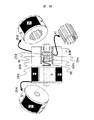
図3は図1の発電機の回転子同磁極中心がずれた場合の概略を示す。
【0018】
図3において、固定子鉄心10には電機子巻線11がスロット内に巻装されており、内部に冷媒が流れる冷却路12をもったハウジング13に結合されている。
【0019】
永久磁石埋め込み型回転子20はシャフト22に固定した第1回転子20Aとシャフト22と分離した第2回転子20Bからなる。勿論、永久磁石埋め込み型回転子のみならず、表面磁石型回転子でも良い。
【0020】
第1回転子20Aには、永久磁石21Aが回転方向に順次異なった極性の磁極が並んでいる。同じく、第2回転子20Bには、永久磁石21Bが回転方向に順次異なった極性の磁極が並んでいる。第1と第2回転子の2つの回転子を同一軸上に配置した界磁用磁石は固定子磁極に対向している。
【0021】
第2回転子20Bの内径側はナット部23Bとなり、それに当たるシャフトにはボルトのネジ部23Aとなり、お互いにネジの機能を持たせて接続すると、第2回転子20Bはシャフトに対して回転しながら軸方向に可変可能とする。
【0022】
また、第2回転子20Bが固定子の中心から所定の変位以上はみ出さないように前記第2回転子20Bの側面から離れたところにはストッパー24を設ける。さらに、サーボ機構であるストッパー駆動用アクチュエータ25を設けて、前記ストッパー24をシャフトと平行に左右に可変可能にすれば、第1界磁用磁石と第2界磁用磁石の磁極中心のずれる値を変えることが出来る。結果的には、電機子巻線11がスロット内に巻装されている固定子に対して、第1界磁用磁石と第2界磁用磁石からなる全体の有効磁束量を制御可能である。
【0023】
上記のようにすることで、トルクの方向に応じて永久磁石の有効磁束量を変化することについて述べる。
【0024】
基本的に固定子には電機子巻線と回転子には永久磁石を用いる発電機において、回転子の回転方向が反対になれば、トルク方向も反対になる。同じく、同じ電動機と働く時、回転子の回転方向が反対になれば、トルク方向も反対になる。
【0025】
また、電動機として働く時と、発電機として働く時の回転子の回転方向が同じであれば、電動機として働く時と、発電機として働く時の回転子が受けるトルクの方向は反対になる。
【0026】
上記に説明した回転方向とトルク方向による基本理論を本発明の実施形態に係る発電機に適用すると以下の通りでる。
【0027】
本発明の発電機が風力の広い範囲で高効率発電を行う一つの実施例として、二つに分割された回転子は以下の状態で運転されれば良い。風が弱い低速回転領域においては、図4に示すように、第1回転子20Aと第2回転子20Bの同磁極の中心が揃えるようにして、固定子磁極と対向する永久磁石による有効磁束量を多くし、高出力特性が得られるようにする。
【0028】
次に、風が強い高速回転領域においては、図5に示すようにシャフト22に対して第2回転子20Bはボルトのネジ部からナット部が外れるように第1回転子20Aと第2回転子20Bの間の間隔が広がりながら同磁極の中心がずれて、固定子磁極と対向する永久磁石による有効磁束量を少なくすることになり、言い換えると弱め界磁効果があり、高回転領域において定出力特性が得られる。
【0029】
第1回転子20Aと第2回転子20Bの間の間隔が広がりながら同磁極の中心がずれて、固定子磁極と対向する永久磁石による有効磁束量が少ない状態の概略を図5に示す。
【0030】
図4と図5にはボルトの頭部61,ボルトのネジ部60とナット部62に対応して書いたのがあるが、ボルトの頭部61は第1回転子20A,ナット部62は第2回転子20Bに相当するものである。ボルトのネジ部60(図3内の23Aに相当する)が同じ方向に回転するとすれば、ナット部62にかかるトルクの方向によって該ナット部62は締まったり外れたりするように、第2回転子20Bも回転子のトルク方向によって同じ働きをする。
【0031】
また、正回転と逆回転の時はトルクの方向が反対になり、正回転の時には図4に示す状態ならば、逆回転の場合には図5の状態になる。
【0032】
勿論、第2回転子20Bの内径側はナット部23Bとなり、それに当たるシャフトにはボルトのネジ部23Aとなり、お互いにネジの機能を持たせて接続するが、ネジの方向を反対にすれば(例えば右ネジから左ネジ)図4と図5の状態が反対になるが、同様に同じ効果が得られる。
【0033】
例えば、風が弱い時、正回転の低速回転領域においては、図4に示すように、第1回転子20Aと第2回転子20Bの同磁極の中心が揃えるようにしたネジの組合せにすれば、固定子磁極と対向する永久磁石による有効磁束量が多くなり、高出力特性が得られる。
【0034】
次に、風が強い時、前記翼70のピッチ制御を行い逆回転になれば、高速回転領域になっても、図5に示すようにシャフト22に対して第2回転子20Bはボルトのネジ部からナット部が外れるように第1回転子20Aと第2回転子20Bの間の間隔が広がりながら同磁極の中心がずれて、固定子磁極と対向する永久磁石による有効磁束量が少なくなり、言い換えると弱め界磁効果があり、高回転領域において高出力特性が得られる。
【0035】
本発明の発電機による誘導起電力の作用について説明する。
【0036】
図6に永久磁石形同期発電機の回転角速度に対する有効磁束,誘導起電力,端子電圧の特性を示す。
【0037】
永久磁石形同期発電機の誘導起電力Eは回転子に配置されている永久磁石が発生する一定磁束Φと発電機の回転角速度ωによって決定される。つまり図6(a)に示す様に、回転子に配置されている永久磁石が発生する一定磁束Φ1が一定ならば、回転角速度ω(回転数)が上昇すると、発電機の誘導起電力E1は比例して上昇する。しかし、電源系統システムの端子電圧とインバータの容量などからインバータの出力電圧は制限があり、定常運転状態の発電機が発生する誘導起電力も制限がある。そのため永久磁石形同期発電機では、ある回転数以上の領域では永久磁石が発生する磁束を減らす、いわゆる弱め界磁制御を行わなくてはならない。
【0038】
誘導起電力が回転角速度に比例して上昇するため、弱め界磁制御の電流も大きくしなければならない故に、1次導体であるコイルに大電流を流す必要があり、おのずとコイルの発生する熱が増大する。そのため、高回転領域における発電機としての効率の低下,冷却能力を超えた発熱による永久磁石の減磁等が起こりうる可能性がある。
【0039】
例えば、図6(a)に示す様に、回転子に配置されている永久磁石が発生する磁束Φ1がある回転角速度ω1(回転数)のポイントで磁束Φ2に変わると、発電機の誘導起電力E1から誘導起電力E2特性に変化することで誘導起電力の最大値を制限することが可能である。
【0040】
図6(b)は同様に回転角速度ω(回転数)に応じてより細かく磁束Φが変われば、誘導起電力Eも一定に保つことが可能であることの概略を示す。
【0041】
図6に示した特性を得る手段の実施例の一つとして、前記第1界磁用磁石はシャフトに固定し、前記第2界磁用磁石はシャフトと分離すると共に、シャフトにはボルトのネジ部と第2界磁用磁石の内側にはナット部になりお互いにネジの機能を持たせて接続し、第2界磁用磁石の側面から離れたところにはストッパーを設け、ストッパーを回転速度に応じてシャフトと平行に可変可能なサーボ機構を持たせた発電機を用いることで可能である。
【0042】
図6に主軸発電機の制御回路の構成図を示す。
【0043】
図6は図1の発電機2の制御ブロック図を示したものである。
【0044】
まず、制御盤(図1内84、若しくは75)から設定された情報,前記風速風向計71からの情報、および永久磁石形同期発電機2の回転数を基に、運転判断部101が永久磁石形同期発電機2の運転動作を判断して電流指令値を出力する。運転判断部101から出力された電流指令値は、現在の永久磁石形同期発電機2の電流値との差分に対して非干渉制御等を行っている電流制御ブロック102に入力する。
【0045】
電流制御ブロック102からの出力は回転座標変換部103で3相の交流に変換され、インバータ104を介して永久磁石形同期発電機2を制御する。また、永久磁石形同期発電機2の各相の電流(少なくとも2相の電流)および回転数を検出し、各相の電流は2軸変換ブロック105で、2軸電流に変換し、電流指令値にフィードバックしている。また、回転数,磁極位置らは検出器106で検出され、磁極位置変換部107と速度変換部108らを通して各制御ブロックにフィードバックされる。
【0046】
尚、図7における実施例では、発電機2の位置・速度センサ、ならびに発電機の電流センサがある場合のものを示したが、これらの一部のセンサを排除し、センサレスにより発電機2タイプの制御構成のものでも、同様に実施可能である。
【0047】
また、本発明の実施の形態の永久磁石形同期発電機は、運転状況に応じて第1回転子と第2回転子の同磁極中心を一致させるようにしたり、ずらしたりすることができるので、前記第1界磁用磁石と第2界磁用磁石の合成磁極位置のずれに応じて前記インバータを制御するコントローラによる電流の進角を補正する機能を持つ。
【0048】
電流の進角を補正する実施例について述べる。
【0049】
前記第1界磁用磁石はシャフトに固定し、前記第2界磁用磁石はシャフトと分離すると共に、シャフトにはボルトのネジ部と第2界磁用磁石の内側にはナット部になりお互いにネジの機能を持たせて接続して運転すると、第2界磁用磁石は回転しながら軸方向に左右に移動する。
【0050】
運転状況に応じて第1回転子と第2回転子の同磁極中心を一致させたり、ずらしたりする場合の回転角と軸方向変位量の関係を図15に示す。
【0051】
図15において、第2回転子の回転角θと軸方向変位量ΔLは比例関係であり、変位測定器64を用いて軸方向変位量ΔLを測定し、制御回路の位置検出回路(図7内106)にフィードバックされ第1界磁用磁石と第2界磁用磁石の合成磁極位置のずれ角に換算した値として、電流の進角を補正する最適制御に用いる。
【0052】
図8は本発明の他の実施形態をなす発電機を示す。
【0053】
前記第1回転子20Aはシャフト22に固定し、前記第2回転子20Bはシャフト22と分離すると共に、シャフトの一部にはボルトのネジ部23Aと第2界磁用磁石の内側にスリーブ41を固定し、かつスリーブ41の内側にナット部
23Bを固定したものを一体化すれば、シャフト22に対して第2回転子20Bはボルトのネジ部からナット部が外れるように、第1回転子20Aと第2回転子20Bの間の間隔が広がりながら回転する。
【0054】
第2界磁用磁石の内側とシャフト22間にはわずかな遊びがあることで、回転と共に第2界磁用磁石の内側とシャフト22間に鎖交磁束の変化が生じると、電食等の障害があるが、前記スリーブ41は鉄より電気抵抗率が高い非磁性体を用いることで、第2界磁用磁石の内側とシャフト22間には磁気的にも、電気的にも絶縁を行う効果がある。
【0055】
前記第2界磁用磁石と前記シャフト間には回転運動と往復運動及び複合運動を案内出来るようにスリーブ41の内側に支持機構40A,40Bを備えた。
【0056】
第2回転子20Bはシャフトの一部にボルトのネジ部23Aとお互いにネジの機能を持たせて接続され、第2界磁用磁石の側面から離れたところには可変可能なストッパー24を設ける。ストッパー24とシャフト間、ストッパーと第2回転子20Bの側面間には回転運動と往復運動及び複合運動を案内出来るように支持機構42,47を設ける。支持機構42はスラスト軸受の機能を持ち、支持機構47はラジアル軸受でありながら回転運動と往復運動及び複合運動を案内する機能を持つ。
【0057】
さらに、ばね48を設けることで、支持機構42はスラスト軸受としてその機能が向上する効果がある。
【0058】
ストッパー24はシャフトと平行に可変可能なサーボ機構の一例として、電磁クラッチについて述べる。
【0059】
電磁クラッチの構成は、ヨーク44にコイル46が巻かれて、ストッパー24は可動鉄心の機能を兼用することで良い。ヨーク44とコイル46は発電機のフレーム49、若しくはハウジングの一部に(図に示せず)固定し、ヨーク44とストッパー24の間にばね45を備えて励磁遮断時の復帰装置の機能を持つ。発電機のフレーム49とシャフト22の間には軸受50で支える。
【0060】
図8はコイル46に無励磁状態の概略であり、図9はコイル46に励磁状態の概略を示す。
【0061】
コイル46を励磁することでヨーク44は強力な電磁石となり、可動鉄心の機能を兼用するストッパー24を吸引する。
【0062】
コイル46を励磁してストッパー24を吸引する時には、シャフト22に対して第2回転子20Bはボルトのネジ部からナット部が外れるように第1回転子
20Aと第2回転子20Bの間の間隔が広がりながら回転するようにトルクを加えれば、コイル46に流す電流の負担が少なくして済む。
【0063】
ここに示した電磁クラッチはストッパー24をシャフトと平行に可変可能なサーボ機構の一例であり、油圧アクチュエータ,回転機とボールネジなどによる直線駆動装置,リニアモータなどを用いることで、より細かなストッパーの位置決めが可能である。
【0064】
図10は第2回転子20Bの内側に固定されるスリーブ41の一例を示す。
【0065】
それらの固定方法の一つとして、第2回転子20Bとスリーブ41からなる2つの部品の接する面のお互いに凸凹を設けて固定した。また、シャフト22に固定した第1回転子20Aとシャフト22と分離した第2回転子20Bの内側違いの概略を示す。
【0066】
図11は本発明の他の実施例を示す。
【0067】
前記第1界磁用磁石と前記第2界磁用磁石が接する前記第1界磁用磁石側面に凹部53を設け、前記第2界磁用磁石には前記スリーブの機能を兼ねた突起部
54を設けた構造である。突起部54はスリーブ41と一体ものでも良いし、第2回転子20Bと一体ものでも良い。よって、スリーブ41の十分なスペースが確保出来、ばね48,支持機構40A,40B,ナット部23Bらを有効に配置することで、第2回転子20Bの軸長積厚が薄い発電機に有効な手法の一つである。
【0068】
図12は本発明の他の実施例を示す。
【0069】
図12に示す基本構成要素は図8と同じであるが、電磁クラッチに相当する一部を変更した一例である。図12はコイル46が励磁状態であり、励磁遮断時はばね45によりヨーク44とストッパー24は切り離れる。また、第2回転子
20Bにトルクが加わるボルトのネジ部23Aとナット部23Bの相互作用によるネジの機能により推力が得られる特性を持つ。よって、ネジとトルクの相互関係でストッパー24を押し出す推力が加われば、コイル46の励磁を遮断するとストッパー24はヨーク44と切り離れる。ヨーク44はアーム52を介してフレーム49、若しくはハウジングの一部に(図に示せず)固定される。
【0070】
図12に示す電磁クラッチは、図8,図9の説明と同じくストッパー24をシャフトと平行に可変可能なサーボ機構の一例であり、油圧アクチュエータ,回転機とボールネジなどによる直線駆動装置,リニアモータなどを用いることで、より細かなストッパー24の位置決めが可能である。
【0071】
勿論、各図に示した各々の構成要素は様々な方法で組合わせることが可能であり、用途に合わせて加えたり、取り外すことは言うまでもない。
【0072】
図13は本発明の他の実施例を示す。
【0073】
本発明の発電機の特徴として、第1回転子20Aはシャフト22に対してしっかり固定されているのに対して、第2回転子20Bはシャフト22に対して自由度を持つことになる。従って、第2回転子20Bとシャフト22間にはわずかな機械的な寸法の遊びがあり、大きなトルクや遠心力などが加わると偏心することもあり得る。よって、第1界磁用磁石を有する第1回転子20Aと前記固定子間のエアギャップGap1より第2界磁用磁石を有する第2回転子20Bと前記固定子間のエアギャップGap2の方が大きくしたことで、偏心による第2回転子20Bと前記固定子との機械的な接続を省く効果がある。
【0074】
ストッパー24と第2回転子20Bの間、第1回転子20Aとに第2回転子
20Bの間には、ばね48,ばね51を複数個設けることで、第2回転子20Bの急激な変動を押さえたり、トルク方向による動きを補助する効果がある。
【0075】
図14は本発明の他の実施形態をなす発電機を示す。
【0076】
前記図2に示した第2回転子のネジ部23をなくし、回転角θ分可変できる機構を設けたことを特徴とする永久磁石形同期発電機である。
【0077】
前記図2に示した第2回転子のネジ部分の代わりに、シャフト22に歯車のように凹凸を設けて、第2回転子20Bの内径側にはシャフトが挿入できるように凸凹を設ける。ただし、シャフト22を第2回転子20Bの内径側に挿入したときには、かみ合う歯の幅より溝の幅を大きくして所定の回転角θ分可変できるようにする。さらに、かみ合う歯と溝の間にはスプリング26とダンパー27を設けることで、急な衝突を和らげる効果がある。
【0078】
以上の本発明の説明では、4極機を対象に述べたが、6極機、又は、8極機以上に適用出来る事は言うまでもない。一例として、図16には本発明を8極機に適用した場合の永久磁石形同期発電機の回転子概略図を示す。また、回転子においては埋め込み磁石形でも、表面磁石形でも適用出来る事は言うまでもない。
【0079】
【発明の効果】
本発明の永久磁石形同期発電機は第1界磁用磁石と第2界磁用磁石に分割した回転子を同一軸上に配置したトルクの方向により第1と第2の界磁用磁石の磁極中心を変化させるという構成により、固定子磁極と対向する永久磁石による有効磁束量を可変出来るという効果がある。
【0080】
特に、風力発電システムの主軸発電機の弱め界磁が簡単に出来、広範囲可変速制御には大きな効果がある。発電機構造が簡単になることにより、発電機が軽量になるため、タワーの構造が簡単になるという効果がある。
【図面の簡単な説明】
【図1】本実施例の永久磁石形同期発電機を配置した風力発電システムの概略を示す。
【図2】図1の風力発電システムタワー上部の概略を示す。
【図3】図1の発電機の回転子同磁極中心がずれた場合概略を示す(その1)。
【図4】図1の発電機の回転子同磁極中心が揃った場合概略を示す。
【図5】図1の発電機の回転子同磁極中心がずれた場合概略を示す(その2)。
【図6】図1の発電機の回転角速度に対する諸特性を示す。
【図7】図1の発電機の制御ブロック図を示す。
【図8】本発明の他の実施形態をなす発電機を示す(アクチュエータOFF状態)。
【図9】本発明の他の実施形態をなす発電機を示す(アクチュエータON状態)。
【図10】本発明の他の実施形態をなす発電機の回転子の内側を示す。
【図11】本発明の他の実施形態をなす発電機の回転子の内側を示す。
【図12】本発明の他の実施形態をなす発電機を示す(アクチュエータON状態)。
【図13】本発明の他の実施形態をなす発電機の回転子概略図を示す(Gapの差を付ける)。
【図14】本発明の他の実施形態をなす発電機の回転子の概略図を示す。
【図15】本発明の他の実施形態をなす発電機の軸方向変位測定の概略図を示す。
【図16】本発明の他の実施形態をなす発電機の回転子概略図を示す(8極機に適用した場合)。
【符号の説明】
2…発電機、10…固定子鉄心、11…電機子巻線、12…冷却路、13…ハウジング、20…回転子、20A…第1回転子、20B…第2回転子、21…永久磁石、21A…第1回転子永久磁石、21B…第2回転子永久磁石、22…シャフト、23…ネジ、24…ストッパー、25…ストッパー駆動用アクチュエータ、26…ばね、27…ダンパー、101…運転判断部、102…電流制御、103…回転座標変換部、104…インバータ、105…2軸変換部。[0001]
BACKGROUND OF THE INVENTION
The present invention relates to a generator using a permanent magnet as a field, and more particularly to a generator of a wind power generation system and a control method therefor, and the rotor of the generator is composed of a first field magnet and a second field magnet. The present invention also relates to a generator capable of changing the magnetic pole center position of a first field magnet and a second field magnet in accordance with the torque direction and changing the effective magnetic flux amount in accordance with the rotational speed, and a control method thereof.
[0002]
[Prior art]
In the permanent magnet field generator according to the prior art, the induced electromotive force E is determined by a constant magnetic flux Φ generated by a permanent magnet disposed in the rotor and the rotational angular velocity ω of the generator. That is, when the rotational angular velocity ω (rotational speed) of the generator increases, the induced electromotive force of the generator increases in proportion.
[0003]
Therefore, high torque can be obtained in the low speed region, but operation in the high speed region is difficult because the variable range of the rotational speed is narrow. In view of this, it is conceivable to expand the high-speed operation range by field weakening control technology.
[0004]
In addition, the generator of the wind power generation system is equipped with a gear mechanism, a pitch motor, etc. in order to ensure a predetermined output in a wide speed range so that it can cope with various wind speed conditions. In some cases, each phase winding of the generator is switched to a low-speed winding and a high-speed winding by using a winding switching device according to the rotational speed of the main shaft.
[0005]
[Problems to be solved by the invention]
Extending the high-speed operation range by the field weakening control technology described in the prior art has a limit due to heat generation due to field weakening current and reduction in efficiency.
[0006]
When a winding switching device is used for each phase winding according to the rotation speed of the main shaft, the number of lead wires from the generator body is large, and the winding switching control device and its structure are complicated. There is.
[0007]
When the structure becomes complicated, the weight of the nacelle part of the wind power generation system increases accordingly, and the structure of the tower needs to be strengthened.
[0008]
[Means for Solving the Problems]
In the wind power generation system, the present invention relates to a main shaft on which blades are mounted, a generator coupled to the main shaft, an inverter electrically connected to the generator, a controller for controlling the inverter, The generator has a means for controlling the pitch of the blades according to the state, a brake for stopping the rotation of the blades, and an anemometer for detecting the state of the wind, and the generator has a primary winding and a stator pole. And a first field magnet having field magnets and shafts facing the stator magnetic poles, wherein the field magnets are arranged with magnetic poles of different polarities sequentially in the rotation direction; A rotor configured to include a second field magnet that is capable of relative rotation with respect to the first field magnet and that has different magnetic poles sequentially arranged behind the rotation; Magnetic acting force between the field magnet and the second field magnet A displacement mechanism for displacing the second field magnet in the axial direction and the rotational direction with respect to the first field magnet in accordance with the balance with the torque direction generated in the trochanter. Depending on the rotation direction of the wing due to the wind condition, the balance between the magnetic force between the first field magnet and the second field magnet and the direction of the rotational torque generated in the rotor The displacement function for aligning the same magnetic pole centers of the first field magnet and the second field magnet and the direction of the rotational torque generated by the rotor are reversed, so that the first field magnet and the second field magnet And a displacement function for shifting the center position of the magnetic poles of the field magnets.
[0009]
DETAILED DESCRIPTION OF THE INVENTION
Embodiments of the present invention will be described below.
[0010]
FIG. 1 shows an outline of a wind power generation system in which a permanent magnet type synchronous generator of this embodiment is arranged.
[0011]
In FIG. 1, a
[0012]
A
[0013]
The
[0014]
FIG. 2 schematically shows components at the top of the
[0015]
In FIG. 2, each
[0016]
Further, as means for controlling the pitch of the
[0017]
FIG. 3 shows an outline when the magnetic pole center of the rotor of the generator of FIG. 1 is shifted.
[0018]
In FIG. 3, an armature winding 11 is wound around a
[0019]
The permanent magnet embedded
[0020]
In the
[0021]
The inner diameter side of the
[0022]
Further, a
[0023]
It will be described that the effective magnetic flux amount of the permanent magnet is changed in accordance with the direction of the torque as described above.
[0024]
Basically, in a generator using an armature winding as a stator and a permanent magnet as a rotor, if the direction of rotation of the rotor is reversed, the direction of torque is also reversed. Similarly, when working with the same motor, if the rotation direction of the rotor is reversed, the torque direction is also reversed.
[0025]
Also, if the direction of rotation of the rotor when working as an electric motor is the same as that when acting as a generator, the direction of torque received by the rotor when working as an electric motor is opposite to that when acting as a generator.
[0026]
The basic theory based on the rotation direction and the torque direction described above is applied to the generator according to the embodiment of the present invention as follows.
[0027]
As an embodiment in which the generator of the present invention performs high-efficiency power generation in a wide range of wind power, the rotor divided into two may be operated in the following state. In the low-speed rotation region where the wind is weak, as shown in FIG. 4, the effective magnetic flux amount by the permanent magnet facing the stator magnetic pole so that the centers of the same magnetic poles of the
[0028]
Next, in a high-speed rotation region where wind is strong, as shown in FIG. 5, the
[0029]
FIG. 5 shows an outline of a state in which the center of the magnetic pole is shifted while the interval between the
[0030]
FIGS. 4 and 5 show the
[0031]
Further, the direction of torque is opposite during forward rotation and reverse rotation, and the state shown in FIG. 4 is obtained during forward rotation, and the state shown in FIG. 5 is obtained during reverse rotation.
[0032]
Of course, the inner diameter side of the
[0033]
For example, when the wind is weak, a combination of screws in which the centers of the same magnetic poles of the
[0034]
Next, when the wind is strong and the pitch of the
[0035]
The effect | action of the induced electromotive force by the generator of this invention is demonstrated.
[0036]
Fig. 6 shows the characteristics of the effective magnetic flux, induced electromotive force, and terminal voltage with respect to the rotational angular velocity of the permanent magnet type synchronous generator.
[0037]
The induced electromotive force E of the permanent magnet type synchronous generator is determined by the constant magnetic flux Φ generated by the permanent magnet arranged on the rotor and the rotational angular velocity ω of the generator. That is, as shown in FIG. 6A, if the constant magnetic flux Φ1 generated by the permanent magnet arranged on the rotor is constant, the induced electromotive force E1 of the generator is increased when the rotational angular velocity ω (number of rotations) is increased. Rise proportionally. However, the output voltage of the inverter is limited due to the terminal voltage of the power system and the capacity of the inverter, and the induced electromotive force generated by the generator in the steady operation state is also limited. Therefore, in the permanent magnet type synchronous generator, so-called field weakening control that reduces the magnetic flux generated by the permanent magnet in a region of a certain number of rotations or more must be performed.
[0038]
Since the induced electromotive force increases in proportion to the rotational angular velocity, it is necessary to increase the current of the field weakening control. Therefore, it is necessary to flow a large current through the coil as the primary conductor, which naturally increases the heat generated by the coil. . For this reason, there is a possibility that the efficiency of the generator as a generator in the high rotation region may be reduced, the permanent magnet may be demagnetized due to heat generation exceeding the cooling capacity, and the like.
[0039]
For example, as shown in FIG. 6 (a), when the magnetic flux Φ1 generated by the permanent magnet arranged in the rotor is changed to the magnetic flux Φ2 at a certain rotational angular velocity ω1 (rotational speed), the induced electromotive force of the generator It is possible to limit the maximum value of the induced electromotive force by changing from E1 to the induced electromotive force E2 characteristic.
[0040]
Similarly, FIG. 6B schematically shows that the induced electromotive force E can be kept constant if the magnetic flux Φ changes more finely according to the rotational angular velocity ω (rotation speed).
[0041]
As one example of means for obtaining the characteristics shown in FIG. 6, the first field magnet is fixed to the shaft, the second field magnet is separated from the shaft, and the shaft is screwed with a bolt. The nut and the inner part of the second field magnet are connected to each other with a screw function, and a stopper is provided at a position away from the side surface of the second field magnet. This is possible by using a generator having a servo mechanism that can be changed in parallel with the shaft.
[0042]
FIG. 6 shows a configuration diagram of a control circuit of the main shaft generator.
[0043]
FIG. 6 shows a control block diagram of the
[0044]
First, based on information set from the control panel (84 or 75 in FIG. 1), information from the wind speed and
[0045]
The output from the
[0046]
In the embodiment in FIG. 7, the position / speed sensor of the
[0047]
In addition, the permanent magnet type synchronous generator according to the embodiment of the present invention can match or shift the same magnetic pole center of the first rotor and the second rotor according to the operating condition. The controller has a function of correcting the advance angle of the current by the controller that controls the inverter in accordance with the deviation of the combined magnetic pole position of the first field magnet and the second field magnet.
[0048]
An embodiment for correcting the advance angle of the current will be described.
[0049]
The first field magnet is fixed to the shaft, and the second field magnet is separated from the shaft. The shaft has a screw portion of a bolt and a nut portion inside the second field magnet. When operating with a screw function, the second field magnet moves to the left and right in the axial direction while rotating.
[0050]
FIG. 15 shows the relationship between the rotation angle and the amount of axial displacement when the same magnetic pole centers of the first rotor and the second rotor are made to coincide or shift according to the operating conditions.
[0051]
In FIG. 15, the rotation angle θ of the second rotor and the axial displacement amount ΔL are proportional to each other, and the
[0052]
FIG. 8 shows a generator according to another embodiment of the present invention.
[0053]
The
[0054]
If there is a slight play between the inside of the second field magnet and the
[0055]
Between the second field magnet and the shaft,
[0056]
The
[0057]
Further, the provision of the
[0058]
As an example of a servo mechanism in which the
[0059]
The electromagnetic clutch may be configured such that the
[0060]
8 shows an outline of the
[0061]
By exciting the
[0062]
When exciting the
[0063]
The electromagnetic clutch shown here is an example of a servo mechanism in which the
[0064]
FIG. 10 shows an example of the
[0065]
As one of those fixing methods, the surfaces where the two parts including the
[0066]
FIG. 11 shows another embodiment of the present invention.
[0067]
A
[0068]
FIG. 12 shows another embodiment of the present invention.
[0069]
The basic components shown in FIG. 12 are the same as those shown in FIG. 8, but a part corresponding to the electromagnetic clutch is changed. In FIG. 12, the
[0070]
The electromagnetic clutch shown in FIG. 12 is an example of a servo mechanism in which the
[0071]
Of course, each component shown in each figure can be combined in various ways, and it goes without saying that it is added or removed according to the application.
[0072]
FIG. 13 shows another embodiment of the present invention.
[0073]
As a feature of the generator of the present invention, the
[0074]
By providing a plurality of
[0075]
FIG. 14 shows a generator according to another embodiment of the present invention.
[0076]
2. A permanent magnet type synchronous generator characterized in that the screw portion 23 of the second rotor shown in FIG.
[0077]
Instead of the screw portion of the second rotor shown in FIG. 2, the
[0078]
In the above description of the present invention, a 4-pole machine has been described, but it goes without saying that it can be applied to a 6-pole machine or an 8-pole machine or more. As an example, FIG. 16 shows a schematic view of a rotor of a permanent magnet type synchronous generator when the present invention is applied to an octupole machine. Further, it goes without saying that the rotor can be applied to either an embedded magnet type or a surface magnet type.
[0079]
【The invention's effect】
The permanent magnet type synchronous generator according to the present invention includes a rotor divided into a first field magnet and a second field magnet on the same axis. The configuration in which the magnetic pole center is changed has an effect that the effective magnetic flux amount by the permanent magnet facing the stator magnetic pole can be varied.
[0080]
In particular, the field weakening of the main shaft generator of the wind power generation system can be easily achieved, which is very effective for wide-range variable speed control. Since the generator structure is simplified, the generator is lighter, and thus the structure of the tower is simplified.
[Brief description of the drawings]
FIG. 1 shows an outline of a wind power generation system in which a permanent magnet type synchronous generator according to the present embodiment is arranged.
2 shows a schematic of the upper part of the wind power generation system tower of FIG.
FIG. 3 shows an outline of the case where the rotor magnetic pole center of the generator of FIG.
4 shows an outline when the magnetic pole centers of the rotor of the generator of FIG. 1 are aligned.
FIG. 5 shows an outline of the case where the center of the rotor of the generator of FIG.
FIG. 6 shows various characteristics with respect to the rotational angular velocity of the generator of FIG.
7 shows a control block diagram of the generator of FIG. 1. FIG.
FIG. 8 shows a generator according to another embodiment of the present invention (actuator OFF state).
FIG. 9 shows a generator according to another embodiment of the present invention (actuator ON state).
FIG. 10 shows an inner side of a rotor of a generator according to another embodiment of the present invention.
FIG. 11 shows the inside of a rotor of a generator that constitutes another embodiment of the present invention.
FIG. 12 shows a generator according to another embodiment of the present invention (actuator ON state).
FIG. 13 is a schematic view of a rotor of a generator that constitutes another embodiment of the present invention (with a gap difference).
FIG. 14 is a schematic view of a generator rotor according to another embodiment of the present invention.
FIG. 15 shows a schematic diagram of axial displacement measurement of a generator according to another embodiment of the present invention.
FIG. 16 is a schematic view of a rotor of a generator that constitutes another embodiment of the present invention (when applied to an 8-pole machine).
[Explanation of symbols]
DESCRIPTION OF
Claims (15)
該主軸と結合された発電機と、
該発電機に電気的に接続されたインバータと、
該インバータを制御するコントローラと、
風の状態に応じて前記翼のピッチを制御する手段と、
前記翼の回転を停止させるブレーキと、
風の状態を検知する風速風向計とを有し、
前記発電機は、
一次巻線及び固定子磁極を有する固定子と、
前記固定子磁極に対向する界磁用磁石及びシャフトを有するものであって、前記界磁用磁石が、回転方向に順次異なった極性の磁極が並んでいる第1の界磁用磁石と、この第1の界磁用磁石に対して相対回転が可能で、回転後方に順次異なった磁性の磁極が並んでいる第2の界磁用磁石とを含み構成された回転子と、
前記第1の界磁用磁石と前記第2の界磁用磁石との間の磁気作用力と前記回転子に発生するトルク方向との釣合いに応じて、前記第1の界磁用磁石に対して前記第2の界磁用磁石を軸方向及び回転方向に変位させる変位機構とを備えており、
前記変位機構は、風の状態による前記翼の回転方向に応じて、前記第1の界磁用磁石と前記第2の界磁用磁石との間の磁気作用力と前記回転子に発生する回転トルクの方向との釣合いにより前記第1の界磁用磁石と前記第2の界磁用磁石の同磁極中心を並ばせる変位機能と、前記回転子の発生する回転トルクの方向が反対になることにより前記第1の界磁用磁石と前記第2の界磁用磁石の同磁極中心位置をずらす変位機能とを備えている
ことを特徴とする風力発電システム。A spindle with wings attached,
A generator coupled to the main shaft;
An inverter electrically connected to the generator;
A controller for controlling the inverter;
Means for controlling the pitch of the wings according to wind conditions;
A brake for stopping the rotation of the wing;
An anemometer that detects the wind condition,
The generator is
A stator having a primary winding and a stator pole;
A field magnet and a shaft facing the stator magnetic pole, wherein the field magnet includes a first field magnet in which magnetic poles of different polarities are sequentially arranged in a rotation direction; A rotor configured to include a second field magnet that is capable of relative rotation with respect to the first field magnet and in which different magnetic poles are sequentially arranged behind the rotation;
Depending on the balance between the magnetic acting force between the first field magnet and the second field magnet and the direction of the torque generated in the rotor, the first field magnet And a displacement mechanism for displacing the second field magnet in the axial direction and the rotational direction,
The displacement mechanism is configured to generate a magnetic action force between the first field magnet and the second field magnet and a rotation generated in the rotor according to a rotation direction of the wing according to a wind state. The displacement function for aligning the magnetic pole centers of the first field magnet and the second field magnet and the direction of the rotational torque generated by the rotor are reversed by the balance with the direction of the torque. A wind power generation system comprising: a displacement function for shifting the magnetic pole center positions of the first field magnet and the second field magnet.
前記変位機構は、
前記翼が正回転している場合、前記第1の界磁用磁石と前記第2の界磁用磁石の同磁極中心を並ばせ、
前記翼が逆回転している場合、前記第1の界磁用磁石と前記第2の界磁用磁石の同磁極中心位置をずらす
ことを特徴とする風力発電システム。The wind power generation system according to claim 1,
The displacement mechanism is
When the blades are rotating forward, the same magnetic pole centers of the first field magnet and the second field magnet are aligned,
A wind power generation system characterized in that, when the blades are rotating in reverse, the same magnetic pole center positions of the first field magnet and the second field magnet are shifted.
前記第1の界磁用磁石は前記シャフトに対して固定されており、
前記第2の界磁用磁石は前記シャフトに対して可動自在に設けられており、
前記第2の界磁用磁石と前記シャフトは、前記シャフトにもたせたボルト機能及び前記第2の界磁用磁石にもたせたナット機能の関係からなるねじ機能によってお互いに接続されている
ことを特徴とする風力発電システム。The wind power generation system according to claim 1,
The first field magnet is fixed to the shaft;
The second field magnet is provided movably with respect to the shaft,
The second field magnet and the shaft are connected to each other by a screw function including a bolt function applied to the shaft and a nut function applied to the second field magnet. Wind power generation system.
前記第2の界磁用磁石の側面には、前記第2の界磁用磁石の所定以上の変位を防止するためのストッパーが設けられており、
前記ストッパーは前記シャフトに対して平行に可変する
ことを特徴とする風力発電システム。In the wind power generation system according to claim 3,
A stopper is provided on a side surface of the second field magnet to prevent displacement of the second field magnet more than a predetermined amount.
The wind power generation system characterized in that the stopper is variable in parallel to the shaft.
前記ストッパーは、回転速度に応じて前記シャフトと平行にサーボ機構によって可変させられる
ことを特徴とする風力発電システム。The wind power generation system according to claim 4,
The wind power generation system according to claim 1, wherein the stopper is variable by a servo mechanism in parallel with the shaft according to a rotational speed.
前記コントローラは、前記第1の界磁用磁石と前記第2の界磁用磁石との合成磁極位置のずれに応じて、前記巻線に供給される電流の進角を制御する
ことを特徴とする風力発電システム。The wind power generation system according to claim 1,
The controller controls an advance angle of a current supplied to the winding in accordance with a deviation of a composite magnetic pole position between the first field magnet and the second field magnet. Wind power generation system.
前記コントローラは、前記第1の界磁用磁石と前記第2の界磁用磁石との合成磁極位置のずれ角に応じて、前記巻線に供給される電流の進角を制御する
ことを特徴とする風力発電システム。The wind power generation system according to claim 1,
The controller controls an advance angle of a current supplied to the winding in accordance with a deviation angle of a composite magnetic pole position between the first field magnet and the second field magnet. Wind power generation system.
前記第2の界磁用磁石と前記シャフトとの間には、回転運動と往復運動及び複合運動を案内するための支持機構が複数設けられている
ことを特徴とする風力発電システム。In the wind power generation system according to claim 3,
A wind power generation system, wherein a plurality of support mechanisms are provided between the second field magnet and the shaft to guide rotational motion, reciprocal motion, and combined motion.
前記第2の界磁用磁石の前後には、前記第2の界磁用磁石の回転運動と往復運動及び複合運動を案内するばねが設けられている
ことを特徴とする風力発電システム。In the wind power generation system according to claim 3,
The wind power generation system according to claim 1, wherein a spring for guiding the rotational motion, the reciprocating motion, and the combined motion of the second field magnet is provided before and after the second field magnet.
前記第2の界磁用磁石と前記シャフトとの間には、それらの間を電気的及び磁気的に絶縁するためのスリーブが設けられており、
前記スリーブは前記第2の界磁用磁石の内周側に固定されている
ことを特徴とする風力発電システム。In the wind power generation system according to claim 3,
Between the second field magnet and the shaft, a sleeve for electrically and magnetically insulating between them is provided,
The wind power generation system according to claim 1, wherein the sleeve is fixed to an inner peripheral side of the second field magnet.
前記スリーブは、鉄よりも電気抵抗率が高い非磁性体である
ことを特徴とする風力発電システム。The wind power generation system according to claim 10,
The wind power generation system according to claim 1, wherein the sleeve is a non-magnetic material having a higher electrical resistivity than iron.
前記第1の界磁用磁石の側面で前記第2の界磁用磁石と接する側面には凹部が設けられており、
前記第2の界磁用磁石の側面で前記第1の界磁用磁石と接する側の側面には突起部が設けられており、
前記突起部は、前記第2の界磁用磁石と前記シャフトとの間を電気的及び磁気的に絶縁するためのスリーブを兼ねている
ことを特徴とする風力発電システム。In the wind power generation system according to claim 3,
A concave portion is provided on a side surface of the first field magnet that is in contact with the second field magnet.
A protrusion is provided on a side surface of the second field magnet that is in contact with the first field magnet.
The wind power generation system according to claim 1, wherein the projecting portion also serves as a sleeve for electrically and magnetically insulating between the second field magnet and the shaft.
前記ストッパーは、前記第2の界磁用磁石と前記シャフトに対して回転運動と往復運動及び複合運動を案内する支持機構を備えている
ことを特徴とする風力発電システム。The wind power generation system according to claim 4,
The wind power generation system according to claim 1, wherein the stopper includes a support mechanism that guides the rotational motion, the reciprocating motion, and the combined motion with respect to the second field magnet and the shaft.
前記第2の界磁用磁石を有する回転子と前記固定子との間のエアギャップは、前記第1の界磁用磁石を有する回転子と前記固定子との間のエアギャップよりも大きい
ことを特徴とする風力発電システム。In the wind power generation system according to claim 3,
The air gap between the rotor having the second field magnet and the stator is larger than the air gap between the rotor having the first field magnet and the stator. Wind power generation system characterized by
前記ストッパーと前記サーボ機構は前記第2の界磁用磁石の内周側に設けられていることを特徴とする風力発電システム。The wind power generation system characterized in that the stopper and the servo mechanism are provided on the inner peripheral side of the second field magnet.
Priority Applications (3)
| Application Number | Priority Date | Filing Date | Title |
|---|---|---|---|
| JP2001053426A JP3873634B2 (en) | 2001-02-28 | 2001-02-28 | Wind power generation system |
| US09/951,966 US6541877B2 (en) | 2001-02-28 | 2001-09-14 | Wind power generation system |
| EP02003283A EP1237263A3 (en) | 2001-02-28 | 2002-02-22 | Wind power generation system |
Applications Claiming Priority (1)
| Application Number | Priority Date | Filing Date | Title |
|---|---|---|---|
| JP2001053426A JP3873634B2 (en) | 2001-02-28 | 2001-02-28 | Wind power generation system |
Publications (3)
| Publication Number | Publication Date |
|---|---|
| JP2002262489A JP2002262489A (en) | 2002-09-13 |
| JP2002262489A5 JP2002262489A5 (en) | 2005-10-06 |
| JP3873634B2 true JP3873634B2 (en) | 2007-01-24 |
Family
ID=18913892
Family Applications (1)
| Application Number | Title | Priority Date | Filing Date |
|---|---|---|---|
| JP2001053426A Expired - Fee Related JP3873634B2 (en) | 2001-02-28 | 2001-02-28 | Wind power generation system |
Country Status (3)
| Country | Link |
|---|---|
| US (1) | US6541877B2 (en) |
| EP (1) | EP1237263A3 (en) |
| JP (1) | JP3873634B2 (en) |
Families Citing this family (61)
| Publication number | Priority date | Publication date | Assignee | Title |
|---|---|---|---|---|
| EP0470630B1 (en) * | 1990-08-10 | 1996-02-07 | Matsushita Electric Industrial Co., Ltd. | Controlling apparatus of steering angle of rear wheels of four-wheel steering vehicle |
| CA2350745C (en) | 1998-11-26 | 2003-11-11 | Aloys Wobben | Azimuthal driving system for wind turbines |
| AU2001267415B2 (en) * | 2000-05-12 | 2005-06-02 | Aloys Wobben | Azimuth drive for wind energy plants |
| US6608397B2 (en) * | 2000-11-09 | 2003-08-19 | Ntn Corporation | Wind driven electrical power generating apparatus |
| JP3879413B2 (en) * | 2001-02-28 | 2007-02-14 | 株式会社日立製作所 | Conveying system and rotating electric machine |
| JP3879412B2 (en) * | 2001-02-28 | 2007-02-14 | 株式会社日立製作所 | Power generation system |
| JP3861610B2 (en) * | 2001-02-28 | 2006-12-20 | 株式会社日立製作所 | Machine Tools |
| DE10127102B4 (en) * | 2001-06-02 | 2013-04-04 | Aloys Wobben | Wind turbine |
| US7773614B1 (en) * | 2001-12-05 | 2010-08-10 | Adaptix, Inc. | Wireless communication subsystem with a digital interface |
| JP3937966B2 (en) * | 2002-07-31 | 2007-06-27 | 株式会社日立製作所 | Rotating electric machine and automobile equipped with it |
| US20040075279A1 (en) * | 2002-10-18 | 2004-04-22 | Breth Newton Roi | Wind powered electric generator |
| US7431567B1 (en) * | 2003-05-30 | 2008-10-07 | Northern Power Systems Inc. | Wind turbine having a direct-drive drivetrain |
| US6946767B2 (en) * | 2003-06-18 | 2005-09-20 | John Reardon | Alternating current generator |
| WO2005028860A1 (en) * | 2003-09-22 | 2005-03-31 | Daiwa House Industry Co., Ltd. | Wind power generating mechanism |
| JP4921173B2 (en) * | 2003-09-30 | 2012-04-25 | ボストン サイエンティフィック リミテッド | Hemostatic clip deployment device and hemostatic clip assembly |
| US7269072B2 (en) * | 2003-12-16 | 2007-09-11 | Micron Technology, Inc. | NROM memory cell, memory array, related devices and methods |
| US7075192B2 (en) * | 2004-04-19 | 2006-07-11 | Northern Power Systems, Inc. | Direct drive wind turbine |
| US7608965B2 (en) * | 2005-09-01 | 2009-10-27 | Wisconsin Alumni Research Foundation | Field controlled axial flux permanent magnet electrical machine |
| JP4817008B2 (en) * | 2005-12-06 | 2011-11-16 | 西芝電機株式会社 | Automatic voltage regulator for synchronous generator or brushless synchronous generator |
| US7508089B2 (en) * | 2006-03-16 | 2009-03-24 | International Components Corporation | Over speed control circuit for a wind turbine generator which maximizes the power exported from the generator over time |
| US7816801B2 (en) | 2006-03-16 | 2010-10-19 | International Components Corporation, Inc. | Speed sensing circuit for a wind turbine generator |
| US7821217B2 (en) | 2006-05-22 | 2010-10-26 | Black & Decker Inc. | Electronically commutated motor and control system employing phase angle control of phase current |
| JP2009126404A (en) * | 2007-11-26 | 2009-06-11 | Hitachi Ltd | Hybrid vehicle |
| DE102008031615A1 (en) * | 2008-07-07 | 2010-01-14 | Voith Patent Gmbh | Underwater power plant and method for its assembly |
| US20110278975A1 (en) * | 2009-01-12 | 2011-11-17 | Redemptive Technologies Limited | Decreased drag high efficiency electric generator |
| US8823241B2 (en) | 2009-01-16 | 2014-09-02 | Boulder Wind Power, Inc. | Segmented stator for an axial field device |
| TWI496936B (en) * | 2009-04-20 | 2015-08-21 | Jiangsu Zhongneng Polysilicon Technology Dev Co Ltd | Processes and an apparatus for manufacturing high purity polysilicon |
| US7863766B2 (en) * | 2009-06-30 | 2011-01-04 | Teco-Westinghouse Motor Company | Power converter for use with wind generator |
| EP2333933B1 (en) * | 2009-12-08 | 2016-03-23 | Siemens Aktiengesellschaft | Arrangement to compensate a non-uniform air gap of an electric machine |
| US8536725B2 (en) * | 2010-02-27 | 2013-09-17 | Mehboob Lakhani | Compact wind and water turbine systems |
| US9154024B2 (en) | 2010-06-02 | 2015-10-06 | Boulder Wind Power, Inc. | Systems and methods for improved direct drive generators |
| US8288982B2 (en) | 2010-12-10 | 2012-10-16 | Current Motor Company, Inc. | Permanent magnet motor with field weakening |
| ITMI20110377A1 (en) * | 2011-03-10 | 2012-09-11 | Wilic Sarl | ROTARY ELECTRIC MACHINE FOR AEROGENERATOR |
| WO2012141932A2 (en) | 2011-04-13 | 2012-10-18 | Smith James S | Flux focusing arrangement for permanent magnets, methods of fabricating such arrangements, and machines including such arrangements |
| JP5722183B2 (en) * | 2011-09-29 | 2015-05-20 | 本田技研工業株式会社 | Electric motor |
| AR083135A1 (en) * | 2011-10-05 | 2013-02-06 | Ind Metalurgicas Pescarmona S A I C Y F | SYNCHRONIC WIND GENERATOR |
| CN102644553B (en) * | 2012-04-25 | 2013-08-28 | 浙江海洋学院 | Ocean wind power generation device based on stepless speed change |
| US8339019B1 (en) | 2012-07-30 | 2012-12-25 | Boulder Wind Power, Inc. | Structure for an electromagnetic machine having compression and tension members |
| US8716913B2 (en) | 2012-08-07 | 2014-05-06 | Boulder Wind Power, Inc. | Devices and methods for magnetic pole and back iron retention in electromagnetic machines |
| ITVR20120178A1 (en) * | 2012-09-04 | 2014-03-05 | Penta Systems S R L | TURBINE AND SUPER-POWER CONTROL SYSTEM OF ITS TURBINE |
| US8736133B1 (en) | 2013-03-14 | 2014-05-27 | Boulder Wind Power, Inc. | Methods and apparatus for overlapping windings |
| JP2015031221A (en) * | 2013-08-05 | 2015-02-16 | 株式会社ジェイテクト | Wind power generation device and rotation transmission device used in the same |
| US9991771B2 (en) * | 2013-11-05 | 2018-06-05 | The University Of Maryland, Baltimore County | Active control system for a variable electromotive-force generator with applications to wind turbines, ships, and hybrid vehicles |
| CN103633792B (en) * | 2013-11-27 | 2017-01-18 | 北京金风科创风电设备有限公司 | Magnet automatic assembly device for wind generating set |
| DE102014206342A1 (en) * | 2014-04-02 | 2015-10-08 | Volkswagen Aktiengesellschaft | Rotor for an electric machine with field weakening device and electric machine |
| GB2526428A (en) * | 2014-04-15 | 2015-11-25 | Whoosh 2013 Ltd | Power generating Apparatus |
| US9899886B2 (en) | 2014-04-29 | 2018-02-20 | Boulder Wind Power, Inc. | Devices and methods for magnetic flux return optimization in electromagnetic machines |
| US10177620B2 (en) | 2014-05-05 | 2019-01-08 | Boulder Wind Power, Inc. | Methods and apparatus for segmenting a machine |
| CN104993655B (en) * | 2015-06-30 | 2018-04-27 | 新疆金风科技股份有限公司 | Alinco assembled system |
| JP6893306B2 (en) * | 2015-10-20 | 2021-06-23 | リニア ラブズ リミテッド ライアビリティ カンパニー | Circumferential magnetic flux electromechanical machine equipped with a magnetic field weakening mechanism and how to use it |
| WO2017078542A1 (en) * | 2015-11-06 | 2017-05-11 | Ateltech As | Scalable electric generator |
| NO341230B1 (en) * | 2015-11-06 | 2017-09-18 | Ateltech As | Scalable electric motor disc stack with multipole stator |
| CN107585176A (en) * | 2016-07-08 | 2018-01-16 | 北京汽车股份有限公司 | Electricity generation system for train |
| US11005313B2 (en) * | 2016-11-21 | 2021-05-11 | Unison Industries, Llc | Skewed rotor designs for hybrid homopolar electrical machines |
| DE102017107897A1 (en) | 2017-04-12 | 2018-10-18 | Wobben Properties Gmbh | Method for cooling a gearless wind turbine |
| US11139708B2 (en) * | 2019-06-20 | 2021-10-05 | Yuan-Kwei Tzeng | Device for use in generating electric power and braking, kit and brake unit of same |
| IT202000015625A1 (en) * | 2020-06-29 | 2021-12-29 | He Powergreen S R L | “Hydrokinetic Turbine” |
| DE102020117257A1 (en) | 2020-07-01 | 2022-01-05 | Schaeffler Technologies AG & Co. KG | Rotor for a synchronous machine and synchronous machine with such a rotor |
| DE102021101904B3 (en) * | 2021-01-28 | 2022-05-12 | Schaeffler Technologies AG & Co. KG | Electrical machine with a mechanical field weakening module |
| EP4064555A1 (en) | 2021-03-25 | 2022-09-28 | Wobben Properties GmbH | Wind turbine and method for controlling a wind turbine |
| CN113217284B (en) * | 2021-05-17 | 2022-07-22 | 广州赛特新能源科技发展有限公司 | Direct-drive breeze wind driven generator system |
Family Cites Families (10)
| Publication number | Priority date | Publication date | Assignee | Title |
|---|---|---|---|---|
| DE2106057A1 (en) | 1971-02-09 | 1972-09-14 | Bosch Gmbh Robert | Alternator |
| DE2231590A1 (en) | 1972-06-28 | 1974-01-10 | Bosch Gmbh Robert | PERMANENT MAGNET GENERATOR |
| GB2225616A (en) * | 1988-11-30 | 1990-06-06 | Wind Energy Group Limited | Power generating system including gearing allowing constant generator torque |
| US5083039B1 (en) * | 1991-02-01 | 1999-11-16 | Zond Energy Systems Inc | Variable speed wind turbine |
| US5821710A (en) | 1996-09-30 | 1998-10-13 | Hitachi Metals, Ltd. | Brushless motor having permanent magnets |
| FR2760492B1 (en) | 1997-03-10 | 2001-11-09 | Jeumont Ind | ELECTRIC POWER GENERATION SYSTEM ASSOCIATED WITH A WIND TURBINE |
| US6600240B2 (en) * | 1997-08-08 | 2003-07-29 | General Electric Company | Variable speed wind turbine generator |
| US6420795B1 (en) * | 1998-08-08 | 2002-07-16 | Zond Energy Systems, Inc. | Variable speed wind turbine generator |
| US6608397B2 (en) * | 2000-11-09 | 2003-08-19 | Ntn Corporation | Wind driven electrical power generating apparatus |
| US20020084655A1 (en) * | 2000-12-29 | 2002-07-04 | Abb Research Ltd. | System, method and computer program product for enhancing commercial value of electrical power produced from a renewable energy power production facility |
-
2001
- 2001-02-28 JP JP2001053426A patent/JP3873634B2/en not_active Expired - Fee Related
- 2001-09-14 US US09/951,966 patent/US6541877B2/en not_active Expired - Fee Related
-
2002
- 2002-02-22 EP EP02003283A patent/EP1237263A3/en not_active Withdrawn
Also Published As
| Publication number | Publication date |
|---|---|
| EP1237263A3 (en) | 2002-09-25 |
| EP1237263A2 (en) | 2002-09-04 |
| JP2002262489A (en) | 2002-09-13 |
| US20020117861A1 (en) | 2002-08-29 |
| US6541877B2 (en) | 2003-04-01 |
Similar Documents
| Publication | Publication Date | Title |
|---|---|---|
| JP3873634B2 (en) | Wind power generation system | |
| JP3879413B2 (en) | Conveying system and rotating electric machine | |
| JP3861610B2 (en) | Machine Tools | |
| JP3879412B2 (en) | Power generation system | |
| JP2002262489A5 (en) | ||
| JP3879415B2 (en) | Washing machine | |
| US7019413B2 (en) | System having an electric device which functions both as an electric motor for driving machines and as a generator to generate electrical power, and having a power source for driving the electric device | |
| EP1237258B1 (en) | Rotational electric machine and a vehicle loaded therewith | |
| EP1814212B1 (en) | Vehicle drive system and vehicle comprising it | |
| JP3879414B2 (en) | Air conditioner | |
| EP2429063A1 (en) | Ac elelctric machine with claw poles | |
| JPH08214519A (en) | Both-saliency motor-generator using permanent magnet | |
| JP4629469B2 (en) | Magnet synchronous rotating electric machine | |
| JP4732930B2 (en) | Synchronous machine | |
| JP2012019642A (en) | Wind turbine generator system | |
| CN107579639B (en) | High-temperature-resistant permanent magnet servo motor | |
| CN116317423B (en) | Bearingless asynchronous motor transmission system and control method thereof | |
| Durairaju et al. | An alternative PM machine configuration suitable for low speed and beyond—rated speed applications | |
| KR100245228B1 (en) | Magnetic circuit of rotator for generating mechanical and electric power | |
| CN117458814A (en) | Double-fed motor and electromagnetic torque converter |
Legal Events
| Date | Code | Title | Description |
|---|---|---|---|
| A621 | Written request for application examination |
Free format text: JAPANESE INTERMEDIATE CODE: A621 Effective date: 20041220 |
|
| A521 | Written amendment |
Free format text: JAPANESE INTERMEDIATE CODE: A523 Effective date: 20050519 |
|
| RD01 | Notification of change of attorney |
Free format text: JAPANESE INTERMEDIATE CODE: A7421 Effective date: 20060418 |
|
| A977 | Report on retrieval |
Free format text: JAPANESE INTERMEDIATE CODE: A971007 Effective date: 20060822 |
|
| TRDD | Decision of grant or rejection written | ||
| A01 | Written decision to grant a patent or to grant a registration (utility model) |
Free format text: JAPANESE INTERMEDIATE CODE: A01 Effective date: 20061003 |
|
| A61 | First payment of annual fees (during grant procedure) |
Free format text: JAPANESE INTERMEDIATE CODE: A61 Effective date: 20061016 |
|
| LAPS | Cancellation because of no payment of annual fees |