JP4921173B2 - Hemostatic clip deployment device and hemostatic clip assembly - Google Patents
Hemostatic clip deployment device and hemostatic clip assembly Download PDFInfo
- Publication number
- JP4921173B2 JP4921173B2 JP2006534166A JP2006534166A JP4921173B2 JP 4921173 B2 JP4921173 B2 JP 4921173B2 JP 2006534166 A JP2006534166 A JP 2006534166A JP 2006534166 A JP2006534166 A JP 2006534166A JP 4921173 B2 JP4921173 B2 JP 4921173B2
- Authority
- JP
- Japan
- Prior art keywords
- clip
- capsule
- yoke
- tension
- control wire
- Prior art date
- Legal status (The legal status is an assumption and is not a legal conclusion. Google has not performed a legal analysis and makes no representation as to the accuracy of the status listed.)
- Active
Links
- 230000002439 hemostatic effect Effects 0.000 title claims description 35
- 239000002775 capsule Substances 0.000 claims description 113
- 238000000926 separation method Methods 0.000 claims description 26
- 238000009434 installation Methods 0.000 claims 1
- 230000033001 locomotion Effects 0.000 description 16
- 239000000463 material Substances 0.000 description 13
- 206010052428 Wound Diseases 0.000 description 10
- 208000027418 Wounds and injury Diseases 0.000 description 10
- 229910001220 stainless steel Inorganic materials 0.000 description 8
- 239000010935 stainless steel Substances 0.000 description 8
- 230000000740 bleeding effect Effects 0.000 description 7
- 230000007246 mechanism Effects 0.000 description 7
- 238000000034 method Methods 0.000 description 7
- 238000005452 bending Methods 0.000 description 5
- 229920000642 polymer Polymers 0.000 description 5
- 238000001356 surgical procedure Methods 0.000 description 5
- 239000000560 biocompatible material Substances 0.000 description 4
- -1 for example Substances 0.000 description 4
- 229910052751 metal Inorganic materials 0.000 description 4
- 239000002184 metal Substances 0.000 description 4
- 230000006378 damage Effects 0.000 description 3
- 230000006870 function Effects 0.000 description 3
- 238000003780 insertion Methods 0.000 description 3
- 230000037431 insertion Effects 0.000 description 3
- 239000004743 Polypropylene Substances 0.000 description 2
- 239000004809 Teflon Substances 0.000 description 2
- 229920006362 Teflon® Polymers 0.000 description 2
- RTAQQCXQSZGOHL-UHFFFAOYSA-N Titanium Chemical compound [Ti] RTAQQCXQSZGOHL-UHFFFAOYSA-N 0.000 description 2
- 229920004738 ULTEM® Polymers 0.000 description 2
- 230000008859 change Effects 0.000 description 2
- 230000008878 coupling Effects 0.000 description 2
- 238000010168 coupling process Methods 0.000 description 2
- 238000005859 coupling reaction Methods 0.000 description 2
- 238000013461 design Methods 0.000 description 2
- 230000002496 gastric effect Effects 0.000 description 2
- 229920001903 high density polyethylene Polymers 0.000 description 2
- 239000004700 high-density polyethylene Substances 0.000 description 2
- 208000014674 injury Diseases 0.000 description 2
- 230000003993 interaction Effects 0.000 description 2
- 239000000314 lubricant Substances 0.000 description 2
- 238000012986 modification Methods 0.000 description 2
- 230000004048 modification Effects 0.000 description 2
- 229910001000 nickel titanium Inorganic materials 0.000 description 2
- HLXZNVUGXRDIFK-UHFFFAOYSA-N nickel titanium Chemical compound [Ti].[Ti].[Ti].[Ti].[Ti].[Ti].[Ti].[Ti].[Ti].[Ti].[Ti].[Ni].[Ni].[Ni].[Ni].[Ni].[Ni].[Ni].[Ni].[Ni].[Ni].[Ni].[Ni].[Ni].[Ni] HLXZNVUGXRDIFK-UHFFFAOYSA-N 0.000 description 2
- 229920001155 polypropylene Polymers 0.000 description 2
- 230000001681 protective effect Effects 0.000 description 2
- 230000035807 sensation Effects 0.000 description 2
- 239000010936 titanium Substances 0.000 description 2
- 230000008733 trauma Effects 0.000 description 2
- 230000002792 vascular Effects 0.000 description 2
- 229910001200 Ferrotitanium Inorganic materials 0.000 description 1
- 239000004696 Poly ether ether ketone Substances 0.000 description 1
- 239000000853 adhesive Substances 0.000 description 1
- 230000001070 adhesive effect Effects 0.000 description 1
- 230000000712 assembly Effects 0.000 description 1
- 238000000429 assembly Methods 0.000 description 1
- 230000009286 beneficial effect Effects 0.000 description 1
- JUPQTSLXMOCDHR-UHFFFAOYSA-N benzene-1,4-diol;bis(4-fluorophenyl)methanone Chemical compound OC1=CC=C(O)C=C1.C1=CC(F)=CC=C1C(=O)C1=CC=C(F)C=C1 JUPQTSLXMOCDHR-UHFFFAOYSA-N 0.000 description 1
- 210000000013 bile duct Anatomy 0.000 description 1
- 229920000249 biocompatible polymer Polymers 0.000 description 1
- 230000005540 biological transmission Effects 0.000 description 1
- 238000001574 biopsy Methods 0.000 description 1
- 230000006835 compression Effects 0.000 description 1
- 238000007906 compression Methods 0.000 description 1
- 239000012141 concentrate Substances 0.000 description 1
- 238000012790 confirmation Methods 0.000 description 1
- 238000010276 construction Methods 0.000 description 1
- 238000007796 conventional method Methods 0.000 description 1
- 230000000994 depressogenic effect Effects 0.000 description 1
- 238000011161 development Methods 0.000 description 1
- 201000010099 disease Diseases 0.000 description 1
- 208000037265 diseases, disorders, signs and symptoms Diseases 0.000 description 1
- 239000013013 elastic material Substances 0.000 description 1
- 238000001861 endoscopic biopsy Methods 0.000 description 1
- 238000002674 endoscopic surgery Methods 0.000 description 1
- 238000001839 endoscopy Methods 0.000 description 1
- 238000001125 extrusion Methods 0.000 description 1
- 239000002783 friction material Substances 0.000 description 1
- 210000001035 gastrointestinal tract Anatomy 0.000 description 1
- 230000035876 healing Effects 0.000 description 1
- 238000002347 injection Methods 0.000 description 1
- 239000007924 injection Substances 0.000 description 1
- 238000001746 injection moulding Methods 0.000 description 1
- 230000003902 lesion Effects 0.000 description 1
- 230000014759 maintenance of location Effects 0.000 description 1
- 238000004519 manufacturing process Methods 0.000 description 1
- 230000013011 mating Effects 0.000 description 1
- 239000000178 monomer Substances 0.000 description 1
- 239000004033 plastic Substances 0.000 description 1
- 229920003023 plastic Polymers 0.000 description 1
- 229920002530 polyetherether ketone Polymers 0.000 description 1
- 229920001296 polysiloxane Polymers 0.000 description 1
- 238000003825 pressing Methods 0.000 description 1
- 230000002685 pulmonary effect Effects 0.000 description 1
- 230000004044 response Effects 0.000 description 1
- 238000004904 shortening Methods 0.000 description 1
- 229920001187 thermosetting polymer Polymers 0.000 description 1
- 230000000451 tissue damage Effects 0.000 description 1
- 231100000827 tissue damage Toxicity 0.000 description 1
- 229910052719 titanium Inorganic materials 0.000 description 1
Images


Classifications
-
- A—HUMAN NECESSITIES
- A61—MEDICAL OR VETERINARY SCIENCE; HYGIENE
- A61B—DIAGNOSIS; SURGERY; IDENTIFICATION
- A61B17/00—Surgical instruments, devices or methods, e.g. tourniquets
- A61B17/068—Surgical staplers, e.g. containing multiple staples or clamps
- A61B17/0682—Surgical staplers, e.g. containing multiple staples or clamps for applying U-shaped staples or clamps, e.g. without a forming anvil
-
- A—HUMAN NECESSITIES
- A61—MEDICAL OR VETERINARY SCIENCE; HYGIENE
- A61B—DIAGNOSIS; SURGERY; IDENTIFICATION
- A61B17/00—Surgical instruments, devices or methods, e.g. tourniquets
- A61B17/08—Wound clamps or clips, i.e. not or only partly penetrating the tissue ; Devices for bringing together the edges of a wound
- A61B17/083—Clips, e.g. resilient
-
- A—HUMAN NECESSITIES
- A61—MEDICAL OR VETERINARY SCIENCE; HYGIENE
- A61B—DIAGNOSIS; SURGERY; IDENTIFICATION
- A61B17/00—Surgical instruments, devices or methods, e.g. tourniquets
- A61B17/12—Surgical instruments, devices or methods, e.g. tourniquets for ligaturing or otherwise compressing tubular parts of the body, e.g. blood vessels, umbilical cord
- A61B17/122—Clamps or clips, e.g. for the umbilical cord
-
- A—HUMAN NECESSITIES
- A61—MEDICAL OR VETERINARY SCIENCE; HYGIENE
- A61B—DIAGNOSIS; SURGERY; IDENTIFICATION
- A61B17/00—Surgical instruments, devices or methods, e.g. tourniquets
- A61B17/12—Surgical instruments, devices or methods, e.g. tourniquets for ligaturing or otherwise compressing tubular parts of the body, e.g. blood vessels, umbilical cord
- A61B17/128—Surgical instruments, devices or methods, e.g. tourniquets for ligaturing or otherwise compressing tubular parts of the body, e.g. blood vessels, umbilical cord for applying or removing clamps or clips
- A61B17/1285—Surgical instruments, devices or methods, e.g. tourniquets for ligaturing or otherwise compressing tubular parts of the body, e.g. blood vessels, umbilical cord for applying or removing clamps or clips for minimally invasive surgery
-
- A—HUMAN NECESSITIES
- A61—MEDICAL OR VETERINARY SCIENCE; HYGIENE
- A61B—DIAGNOSIS; SURGERY; IDENTIFICATION
- A61B34/00—Computer-aided surgery; Manipulators or robots specially adapted for use in surgery
- A61B34/70—Manipulators specially adapted for use in surgery
- A61B34/71—Manipulators operated by drive cable mechanisms
-
- A—HUMAN NECESSITIES
- A61—MEDICAL OR VETERINARY SCIENCE; HYGIENE
- A61B—DIAGNOSIS; SURGERY; IDENTIFICATION
- A61B34/00—Computer-aided surgery; Manipulators or robots specially adapted for use in surgery
- A61B34/70—Manipulators specially adapted for use in surgery
- A61B34/76—Manipulators having means for providing feel, e.g. force or tactile feedback
-
- A—HUMAN NECESSITIES
- A61—MEDICAL OR VETERINARY SCIENCE; HYGIENE
- A61B—DIAGNOSIS; SURGERY; IDENTIFICATION
- A61B17/00—Surgical instruments, devices or methods, e.g. tourniquets
- A61B17/12—Surgical instruments, devices or methods, e.g. tourniquets for ligaturing or otherwise compressing tubular parts of the body, e.g. blood vessels, umbilical cord
- A61B17/122—Clamps or clips, e.g. for the umbilical cord
- A61B17/1227—Spring clips
-
- A—HUMAN NECESSITIES
- A61—MEDICAL OR VETERINARY SCIENCE; HYGIENE
- A61B—DIAGNOSIS; SURGERY; IDENTIFICATION
- A61B17/00—Surgical instruments, devices or methods, e.g. tourniquets
- A61B17/00234—Surgical instruments, devices or methods, e.g. tourniquets for minimally invasive surgery
- A61B2017/00292—Surgical instruments, devices or methods, e.g. tourniquets for minimally invasive surgery mounted on or guided by flexible, e.g. catheter-like, means
- A61B2017/003—Steerable
-
- A—HUMAN NECESSITIES
- A61—MEDICAL OR VETERINARY SCIENCE; HYGIENE
- A61B—DIAGNOSIS; SURGERY; IDENTIFICATION
- A61B17/00—Surgical instruments, devices or methods, e.g. tourniquets
- A61B2017/00831—Material properties
- A61B2017/0084—Material properties low friction
- A61B2017/00845—Material properties low friction of moving parts with respect to each other
-
- A—HUMAN NECESSITIES
- A61—MEDICAL OR VETERINARY SCIENCE; HYGIENE
- A61B—DIAGNOSIS; SURGERY; IDENTIFICATION
- A61B17/00—Surgical instruments, devices or methods, e.g. tourniquets
- A61B2017/00831—Material properties
- A61B2017/0084—Material properties low friction
- A61B2017/00849—Material properties low friction with respect to tissue, e.g. hollow organs
-
- A—HUMAN NECESSITIES
- A61—MEDICAL OR VETERINARY SCIENCE; HYGIENE
- A61B—DIAGNOSIS; SURGERY; IDENTIFICATION
- A61B17/00—Surgical instruments, devices or methods, e.g. tourniquets
- A61B17/12—Surgical instruments, devices or methods, e.g. tourniquets for ligaturing or otherwise compressing tubular parts of the body, e.g. blood vessels, umbilical cord
- A61B2017/12004—Surgical instruments, devices or methods, e.g. tourniquets for ligaturing or otherwise compressing tubular parts of the body, e.g. blood vessels, umbilical cord for haemostasis, for prevention of bleeding
-
- A—HUMAN NECESSITIES
- A61—MEDICAL OR VETERINARY SCIENCE; HYGIENE
- A61B—DIAGNOSIS; SURGERY; IDENTIFICATION
- A61B17/00—Surgical instruments, devices or methods, e.g. tourniquets
- A61B17/28—Surgical forceps
- A61B17/29—Forceps for use in minimally invasive surgery
- A61B17/2909—Handles
- A61B2017/2912—Handles transmission of forces to actuating rod or piston
- A61B2017/2919—Handles transmission of forces to actuating rod or piston details of linkages or pivot points
- A61B2017/292—Handles transmission of forces to actuating rod or piston details of linkages or pivot points connection of actuating rod to handle, e.g. ball end in recess
-
- A—HUMAN NECESSITIES
- A61—MEDICAL OR VETERINARY SCIENCE; HYGIENE
- A61B—DIAGNOSIS; SURGERY; IDENTIFICATION
- A61B34/00—Computer-aided surgery; Manipulators or robots specially adapted for use in surgery
- A61B34/70—Manipulators specially adapted for use in surgery
- A61B34/71—Manipulators operated by drive cable mechanisms
- A61B2034/715—Cable tensioning mechanisms for removing slack
-
- A—HUMAN NECESSITIES
- A61—MEDICAL OR VETERINARY SCIENCE; HYGIENE
- A61B—DIAGNOSIS; SURGERY; IDENTIFICATION
- A61B90/00—Instruments, implements or accessories specially adapted for surgery or diagnosis and not covered by any of the groups A61B1/00 - A61B50/00, e.g. for luxation treatment or for protecting wound edges
- A61B90/03—Automatic limiting or abutting means, e.g. for safety
- A61B2090/033—Abutting means, stops, e.g. abutting on tissue or skin
- A61B2090/034—Abutting means, stops, e.g. abutting on tissue or skin abutting on parts of the device itself
-
- A—HUMAN NECESSITIES
- A61—MEDICAL OR VETERINARY SCIENCE; HYGIENE
- A61B—DIAGNOSIS; SURGERY; IDENTIFICATION
- A61B90/00—Instruments, implements or accessories specially adapted for surgery or diagnosis and not covered by any of the groups A61B1/00 - A61B50/00, e.g. for luxation treatment or for protecting wound edges
- A61B90/03—Automatic limiting or abutting means, e.g. for safety
- A61B2090/037—Automatic limiting or abutting means, e.g. for safety with a frangible part, e.g. by reduced diameter
-
- A—HUMAN NECESSITIES
- A61—MEDICAL OR VETERINARY SCIENCE; HYGIENE
- A61B—DIAGNOSIS; SURGERY; IDENTIFICATION
- A61B90/00—Instruments, implements or accessories specially adapted for surgery or diagnosis and not covered by any of the groups A61B1/00 - A61B50/00, e.g. for luxation treatment or for protecting wound edges
- A61B90/03—Automatic limiting or abutting means, e.g. for safety
- A61B2090/038—Automatic limiting or abutting means, e.g. for safety during shipment
Description
この発明は経内視鏡的に張力部材を解除するクリップに関する。 The present invention relates to a clip for releasing a tension member transendoscopically.
胃腸(GI)系、胆管系、脈管系、および他の体管腔の病変を治療する内視鏡的手術は、ますます一般的になってきている。
創傷部の縁を互いにクランプすることによって内部出血を止める止血クリップを展開するために、止血クリッピング器具を内視鏡を通して挿入してきた。遠位端に取り付けられているクリップを備えたそのようなクリッピング器具は、出血位置へと内視鏡を通して挿入することができる。次いでクリップを出血部位上の位置にくるよう遠隔的に操作し、創傷部上でクランプし、器具から取り外す。
Endoscopic surgery to treat lesions in the gastrointestinal (GI) system, bile duct system, vascular system, and other body lumens is becoming increasingly common.
A hemostatic clipping instrument has been inserted through an endoscope to deploy a hemostatic clip that stops internal bleeding by clamping the wound edges together. Such a clipping instrument with a clip attached to the distal end can be inserted through the endoscope into the bleeding position. The clip is then remotely manipulated to be in position on the bleeding site, clamped on the wound, and removed from the instrument.
内視鏡操作者が面している1つの課題は、効果的に出血を止めるために止血クリップを創傷部上に適切に配置することである。クリップが不適切に展開されると、出血を止めるために追加のクリップが必要になることがあり、手術の必要時間および複雑性が増し、追加の医療用デバイスを患者の体内に留置することになる。またデバイス操作者は、展開操作中に、展開されたクリップの状態を確認することも重要である。例えば、器具を内視鏡から抜去する前に、操作者は、組織上でクランプされているクリップが器具から解除されないことがないように、展開されたクリップがすべて、完全に展開され器具から完全に解除されているという明白な指示を得るべきである。 One challenge facing endoscopy operators is to properly place a hemostatic clip on the wound site to effectively stop bleeding. If the clip is deployed improperly, additional clips may be required to stop bleeding, increasing the time and complexity of surgery and placing additional medical devices in the patient's body. Become. It is also important for the device operator to check the state of the deployed clip during the deployment operation. For example, before removing the instrument from the endoscope, the operator may ensure that all deployed clips are fully deployed and completely removed from the instrument so that clips clamped on the tissue are not released from the instrument. You should get an explicit indication that it has been lifted.
1態様では、本発明は、カプセルおよびカプセル内部に摺動可能に装着されたクリップを含み、クリップをカプセル内部で近位側に引き込むとクリップのアームが互いに閉位置へと引き寄せられ、クリップをカプセル内部の所定の位置まで引き込むとアームの少なくとも1つの当接面がカプセルの対応面に接触するようになっており、クリップ・アームに連結され、クリップ・アームを開形状、組織を受ける形状に向かって付勢する張力部材、およびカプセル内部で摺動可能に受けられ、張力部材に解除可能に連結され、デリバリー・デバイスに連結されたクリップ・アセンブリを維持するようにデリバリー・デバイスの制御要素の球コネクタを受ける球空洞部を含むヨークと組み合わさって、クリップが閉じていることを示す第1の使用者フィードバックを生成し、制御要素がヨークをデリバリー・デバイスから切り離し、第2の使用者フィードバックを生成するように脆弱であり、ヨークを張力部材から解除することによって第3の使用者フィードバックを生成する、デリバリー・デバイスに装着するための止血クリップ・アセンブリを対象とする。 In one aspect, the present invention includes a capsule and a clip slidably mounted within the capsule, and when the clip is retracted proximally within the capsule, the arms of the clip are pulled toward each other to close the clip. When retracted to a predetermined position inside the arm, at least one abutment surface of the arm comes into contact with the corresponding surface of the capsule, and is connected to the clip arm so that the clip arm is in an open shape and a shape for receiving tissue. Urging tension member and a ball of the control element of the delivery device to maintain a clip assembly slidably received within the capsule and releasably coupled to the tension member and coupled to the delivery device A first user, in combination with a yoke including a spherical cavity for receiving a connector, indicating that the clip is closed Generating feedback, the control element is vulnerable to disconnect the yoke from the delivery device and generate a second user feedback, generating a third user feedback by releasing the yoke from the tension member; Intended for a hemostatic clip assembly for attachment to a delivery device.
止血クリップは、手術中に形成された切開部ならびに組織への他の外傷により生じた創傷部からの出血を止めるために、日常的に使用されている。最も単純な形態では、これらのクリップは、創傷部を囲む組織を把持し創傷縁部を互いに引き寄せることによって創傷部の自然治癒過程を可能にする。内視鏡的止血クリップは、外科手術および/または疾病等による組織の損傷によって生じた体内出血を止めるために使用される。クリップを患者体内の所望の位置へと導き組織上の適切な場所に配置し展開するために、専用の内視鏡的止血クリッピング・デバイスを使用する。次いで、クリップを患者の体内に留置してクリッピング・デバイスを抜去する。 Hemostatic clips are routinely used to stop bleeding from wounds caused by incisions made during surgery as well as other trauma to the tissue. In its simplest form, these clips allow for the natural healing process of the wound by grasping the tissue surrounding the wound and pulling the wound edges together. Endoscopic hemostatic clips are used to stop internal bleeding caused by tissue damage due to surgery and / or disease. A dedicated endoscopic hemostatic clipping device is used to guide the clip to the desired location within the patient and place and deploy it to the appropriate location on the tissue. The clip is then placed in the patient's body and the clipping device is removed.
内視鏡的止血クリッピング・デバイスは、例えば胃腸管、肺系、脈管系の内部または他の管腔および導管内部などの、患者体内の深部の患部組織に到達するように設計されている。これらの部分を治療する手術の間、治療する組織にアクセスしそれを可視化するために、一般的には内視鏡を使用する。例えば、クリッピング・デバイスは内視鏡の作業ルーメンを通して導入することができる。このような「経内視鏡的な」内視鏡的止血クリッピング・デバイスの設計および構造には、いくつかの問題がある。内視鏡的クリッピング・デバイスは内視鏡のルーメンに嵌合するよう十分に小さくなければならず、同時に止血クリップの確実な配置および作動が可能であるように設計されていなければならない。止血クリップが組織上の定位置に適切にロックされたか、かつデバイス自体を内視鏡を通して抜去する前にデバイスから解除されたかについて操作者が迷うことのないように、好ましくは操作者へのフィードバックも実行される。 Endoscopic hemostatic clipping devices are designed to reach deep diseased tissue within a patient, such as, for example, inside the gastrointestinal tract, pulmonary system, vascular system, or other lumens and conduits. During surgery to treat these parts, an endoscope is typically used to access and visualize the tissue to be treated. For example, a clipping device can be introduced through the working lumen of an endoscope. There are several problems with the design and construction of such “transendoscopic” endoscopic hemostatic clipping devices. The endoscopic clipping device must be small enough to fit into the lumen of the endoscope and at the same time be designed to allow reliable placement and operation of the hemostatic clip. Feedback to the operator, preferably so that the operator will not be confused as to whether the hemostatic clip has been properly locked in place on the tissue and released from the device before removing the device itself through the endoscope Is also executed.
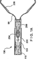
図1は本発明の例示的実施形態による経内視鏡止血クリッピング・デバイスの側面図である。このデバイスは内視鏡のルーメンを通して止血クリップを挿入し、クリップを創傷部上に配置し、患部組織上でクランプし、かつ展開するために使用する手動操作式器具である。器具はさらに、定位置でクランプした後に止血クリップを解除し、内視鏡を通して抜去されるように設計されている。例示的なデバイスの操作および構造をより詳細に説明するために、3つの主要な構成部品に分類することができる。図に示すように、止血クリッピング・デバイス100は、ハンドル・アセンブリ102、シャフト部104、およびクリップ・アセンブリ106を含む。クリップ・アセンブリ106は図1Aでより明確に示されている。
FIG. 1 is a side view of a transendoscopic hemostatic clipping device according to an exemplary embodiment of the present invention. This device is a manually operated instrument used to insert a hemostatic clip through the lumen of the endoscope, place the clip on the wound, clamp it on the affected tissue, and deploy. The instrument is further designed to release the hemostatic clip after being clamped in place and removed through the endoscope. To describe the operation and structure of an exemplary device in more detail, it can be classified into three main components. As shown, the
ハンドル・アセンブリ102は、クリップを展開しクランプする機械的作動力を供給する構成部品を形成する。この実施形態では、デバイス100は手動操作式である(すなわち、使用者が必要な力を手で加えることによって止血クリップに関するすべての機能を実行する)。ハンドル・アセンブリ102は、一般に内視鏡的生検デバイスまたは同様の用途で使用されるタイプの、従来のハンドル・アセンブリと同様の方法で製造することができる。ハンドル・アセンブリ102によって使用者は、シャフト部104を通りデバイス100の遠位端のクリップ・アセンブリ106へと延びる、制御ワイヤ118または他の力伝達部材を動かすことが可能になる。ハンドル・アセンブリ102は、使用者がデバイスを安定させデバイスに力を加えるために把持することのできるハンドル本体108を含む。使用者がワイヤ118を所望通りに容易に引き寄せまたは押し出すことができるように、摺動スプール110が制御ワイヤ118に連結されている。
The
図1および2を参照すると、摺動スプール110は、ハンドル・アセンブリ102内部でその位置を維持するスロット116に沿って摺動することができるように、ハンドル本体108に設置されている。摺動スプール110は制御ワイヤ118に連結されているので、使用者は、ハンドル本体108を把持し摺動スプール110をスロット116に沿って動かすことによって、制御ワイヤ118を操作することができる。摺動スプール110、ひいては制御ワイヤ118を所望の位置に向かって付勢するように、戻しばね112をハンドル本体108内部に設けることができる。本実施形態では、摺動スプール110は近位側位置へと付勢されている。ハンドル・アセンブリ102もまた、制御ワイヤ118を受けシャフト部104をハンドル・アセンブリ102に取り付ける連結部114を含むことができる。
With reference to FIGS. 1 and 2, the
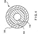
シャフト部104は、ハンドル・アセンブリ102をクリップ・アセンブリ106に機械的に連結し、クリップ・アセンブリ106とともに内視鏡のルーメン内部に挿入されるように設計されている。図3および4に示すように、シャフト部104は、トルクをデバイス100の近位端から遠位端へと伝達し、シャフト部104に構造的強度をもたらすように設計された外側の可撓性コイル130を含む。コイル130は生検デバイスで使用さ
れる従来のコイルとすることができ、例えば単一巻回されたワイヤを含むことができる。巻回されたワイヤは円形、正方形、または矩形の交差部を含むことができ、例えばステンレス鋼などの生体適合性材料から作ることができる。既知の製造方法に従って、シャフト部104上に追加の保護的および低摩擦性外層を含むこともできる。
The
制御ワイヤ118はハンドル・アセンブリ102に加えられた機械的な力をクリップ・アセンブリ106に伝達する。制御ワイヤ118は、摺動スプール110などハンドル102の可動部分に、既知の方法を使用して取り付けられた近位端を有する。アセンブリの構造的一体性を維持するために、ステンレス鋼または他の高降伏の生体適合性材料を使用して制御ワイヤ118を製造することができる。張力下で、制御ワイヤ118が伸長しないようにすることも重要であるが、それはワイヤが伸長すると、ハンドル102が所望の操作を実行するためにより長い距離を移動しなければならないからである。図5に示すように制御ワイヤ118の遠位端は、後述するように制御ワイヤ118をクリップ・アセンブリ106の適切な要素に連結するために使用される球140で終端している。この実施形態では、制御ワイヤ118の直径は、その近位端から遠位側先細部144の近位端まで、ほぼ一定である。球140の直径は、ヨーク204に取り付けやすくするために制御ワイヤ118の直径よりも大きくすることができる。制御ワイヤ118はヨーク204から摺動スプール110まで、デバイス100の長さにわたって延びることができ、デバイス100を通して長手方向に摺動することができる。制御ワイヤ118は、例えばステンレス鋼や他の生体適合性金属から作ることができる。
The
制御ワイヤ118はまた、ハンドル・アセンブリ102を通して所定の張力が加えられると切り離されるように設計された、より小径の部分142を含むことができる。制御ワイヤ118の本体とより小径の部分142の間に先細部144を使用して、応力が集中することがあり破断点をより予測不可能なものにすることのある段や他の不連続部を設けずに移行することができる。後段でさらに詳述するが、より小径の部分142の1つの目的は、クリップを適切に展開した後で止血クリップを止血クリッピング・デバイス100から解除しやすくすることである。より小径の部分142の、制御ワイヤ118に沿った位置はデバイス100の特定の要件を考慮に入れて変化させることができることを、当業者には容易に理解するであろう。
The
図3および4に示すように、シャフト部104の構造に内側シース132を使用することができる。内側シース132は、制御ワイヤ118の外径とシャフト部104の内径の間に低摩擦の軸受面を提供する。内側シース132は、例えばTeflon(商標)、HDPEまたはポリプロピレンなどの低摩擦材料から形成することができる。例示的な1実施形態では、内側シース132はシャフト部104内部で摺動可能であり、制御ワイヤ118は内側シース132内部で摺動可能であり、複数軸受面の低摩擦システムを形成している。さらに摩擦を軽減するために、シャフト部104の長さに沿って内側シース132の内面および外面に生体適合性の潤滑剤を塗布することができる。この目的のために、例えばシリコーン潤滑剤を使用することができる。
As shown in FIGS. 3 and 4, an
図1および2に示すように、シャフト部104の設計には摺動可能なオーバーシース150を含むことができる。オーバーシース150は、止血クリッピング・デバイス100が内視鏡のルーメンを通過する間、金属クリップ・アセンブリ106および金属コイル130から内視鏡のルーメン内側を保護するように設計されている。クリッピング・デバイス100、より具体的にはクリップ・アセンブリ106が内視鏡を通過した後、オーバーシース150を引き寄せ、クリッピング・デバイス100の遠位部分を露出させることができる。オーバーシース150は、クリップ・アセンブリ106を選択的に覆うまたは露出させるように、例えばクリッピング・デバイス100の遠位部分上で摺動可能な単一管腔のプラスチック押出成形要素として形成することができる。1実施形態では、オーバー
シース150は、例えばTeflon(商標)、HDPE、ポリプロピレンなどの低摩擦ポリマー、または同様の材料から形成することができる。
As shown in FIGS. 1 and 2, the design of the
オーバーシース150は、把持部152および細長い本体154を含むことができる。把持部152は、使用者がオーバーシース150をクリッピング・デバイス100のシャフト上で簡単に摺動できるようにするハンドルとして設計されている。例示的な1実施形態では、把持部152は使用者に優れた把持面を提供するようにゴム様材料から作られる。例えば、TPEなどの射出成形可能なポリマーを使用して把持部152を製造することができる。細長い本体154はクリッピング・デバイス100のシャフトを取り囲むほぼ円筒形の外殻として形成することができる。細長い本体154は、当業者であれば理解できるであろう従来の方法を使用して、把持部152に取り付けることができる。
The
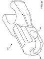
図6および7に示すように、例示的な把持部152はクリッピング・デバイス100のシャフトを受けるために使用することのできる中心中空チャネル160を含む。中心中空チャネル160は細長い本体154と位置合わせされ、クリッピング・デバイス100のシャフトを収容する連続的なチャネルを形成する。把持部152の材料は、中心中空チャネル160とクリッピング・デバイス100のシャフトの間で接着剤または機械的締結デバイスを使用せずに締まり嵌めが可能であるように、高い摩擦係数を有することができる。1実施形態では、クリッピング・デバイス100のシャフトとオーバーシース150アセンブリの間に追加的な摩擦をもたらすように、中心中空チャネル160の内径に摩擦ボス158を設けることができる。摩擦ボス158は例えばオーバーシース150の内径から延びる突起として形成することができ、様々な太く短いまたは細長い形状とすることができる。これら2つの構成部品間の摩擦量は、望んでいない相対動作が起こらないようにすると同時に使用者が必要なときにオーバーシース150を近位側および遠位側に比較的簡単に摺動することができるように、均衡をとることができる。
As shown in FIGS. 6 and 7, the
クリッピング・デバイス100を内視鏡に挿入する間、オーバーシース150が遠位端から摺動して離れないように、クリッピング・デバイス100にシース止め156を設けることができる。図2および8の例示的な実施形態に示すように、オーバーシース150が引き寄せられクリップ・アセンブリ106が露出されることを防ぐために、シース止め156は把持部152が近位側に摺動することを物理的に阻止する。シース止め156は、外科手術中に操作者が手を伸ばし操作することができる、シャフト部104の近位端付近の定位置に、簡単にスナップ嵌めするように設計されている。クリップ・アセンブリ106が内視鏡に挿入され、患者の体内の所望の位置に到達すると、使用者が把持部152を近位側に動かしてクリップ・アセンブリ106を露出させるように、シース止め156をシャフト部104から取り外すことができる。
A
シース止め156とシャフト部104の間の連結は、例えばシャフト部104上でスナップ嵌めするように設計された、向かい合うフィンガー162、164の対を含むことができる。フィンガー162、164は、それらの間にシャフト部104の本体を確実にかつ解除可能に保持するように協働する。フィンガー162、164はそれぞれ、ガイド部170、172、シャフト・チャネル部166、168、およびブロック部174、176を含む。シース止め156の細長い本体154上への挿入は、シャフト部104の本体をガイド部170、172間に押し付け、フィンガー162、164を拡げ、シャフト104をフィンガー162、164間にさらに挿入することによって実現される。ガイド部170、172およびブロック部174、176は、シャフト部104のチャネル部166、168への挿入が、シャフト部104を反対方向に動かすことよりも少ない労力しか必要としない形状である。
The connection between the
シャフト部104をチャネル部166、168内に配置した後、フィンガー162、1
64はスナップ式に非伸展位置に戻り、それらの間の定位置にシャフト部104を保持する。シース止め156をシャフト部104から引き離すことによってシャフト部104を取り外す。ブロック部174、176の形状によって、シャフト部104の取り外しには、中に挿入するときよりも大きな力を加える必要がある。フィンガー162、164の過度の伸展によって引き起こされることのある、デバイスへの損傷を防ぐために、シャフト部104が把持部161の方へ動くことを制限するように、止め具180をシース止め156に設けることもできる。シース止め156は、ポリマーなどの弾性材料から形成することができ、射出成形によって製造することができる。
After placing the
64 snaps back to the non-extension position and holds the
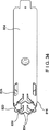
クリップ・アセンブリ106はクリッピング・デバイス100の遠位端に配設されており、制御ワイヤ118を近位側および遠位側に動かすことを、止血クリップ90の展開および解除に必要な動作に変換する機構を含む。図9、10および11はそれぞれ、クリップを折畳み形状で有するクリップ・アセンブリ106を含むクリッピング・デバイス100の遠位側の側面図、頂面図および斜視図を示す。この形状は、例えば、クリッピング・デバイス100を発送し、クリッピング・デバイス100を内視鏡のルーメンを通して挿入するために使用する。クリップ・アセンブリ106の構成部品のいくつかは、クリップ・アセンブリ106に構造的外殻をもたらすカプセル200、開位置と閉位置の間で動くクリップ・アーム208、コイル130に取り付けられたブシュ202、および制御ワイヤ球140と張力部材206を連結するヨーク204を含む。
例示的な実施形態に示すように、カプセル200の近位端はブシュ202の遠位端上を摺動する。カプセル200とブシュ202の間で機械的一体性が一時的に維持されるように、ブシュ202内にロックされるように設計されたカプセル・タブ212によって、2つの例示的な構成部品の間でロック構成がもたらされる。カプセル200内部には、制御ワイヤ118によって加えられた力をクリップ・アーム208に伝達するヨーク204および張力部材206が収容されている。制御ワイヤ118の遠位端に形成された球140は、ヨーク204の近位端に形成された受けソケット210と対合する。後述するように、2つの構成部品が互いに解除可能に連結されるように張力部材206から延びる雄型C字形断面214が、ヨーク204に形成された対応する雌型C字形断面216内で受けられる。閉形状のクリップ・アーム208は、アームが開かないようにカプセル200内部に一部が収容されている半径部分300を含む。各クリップ・アーム208は張力部材206上を延び、アーム208の動きをさらに制御するためにヨーク張出し部254の下を摺動する近位端252を含む。
As shown in the exemplary embodiment, the proximal end of
図12および13は、クリップ・アーム208が完全開位置にある、開形状のクリップ・アセンブリ106の例示的な1実施形態の頂面図および斜視図を示す。開形状は、制御ワイヤ118の球140がヨーク204および張力部材206を含むアセンブリをカプセル200内部で遠位側に押し出すように、図1に示す摺動スプール110を遠位側に動かすときに得られる。後述するように、クリップ・アーム208の遠位端は開位置に向かって付勢されており、カプセル200によって制限されないときはいつでもこの位置に復帰する。例示的な実施形態では、クリップ・アーム208が、図14および15に示す、カプセル200の遠位端から延びる折り曲げられた遠位側折り曲げタブ220に乗るとき、クリップ・アーム208が最大に開く。この実施形態では、タブ220はカム面を形成し、クリップ・アーム208はタブ220によって撓むカム従動子として作用する。さらに折り曲げタブ220は、カプセル200内に保持するために張力部材206に遠位側止め具を提供することもできる。したがって、摺動スプール110を遠位側に動かすことによって使用者はクリップ・アーム208を開き、それらの間に組織を把持する準備をする。
12 and 13 show a top and perspective view of an exemplary embodiment of the open-shaped
使用者が摺動スプール110を近位側に動かすと、カプセル200内部のアセンブリもまた近位側に動き、クリップ・アーム208がカプセル200内部で引き寄せられる。ク
リップ・アーム208がカプセル200内部で近位側に動くと、クリップ止めショルダー(CSS)222がカプセル200の遠位部、例えば折り曲げタブ220に接触する。CSS222とカプセル200のこの相互作用によって、使用者は、摺動スプール110の動きへの抵抗が増加する形で第1の触覚フィードバックを得ることができる。このフィードバックは、操作者に、ハンドル制御をさらに動かすことによって止血クリップ90がクリップ・アセンブリ106から展開されるという明白な指示を与える。次いで操作者は、クリップ90の現在の位置が許容可能かどうかを判断することができる。位置が許容可能であれば、操作者は、ヨーク204を張力部材206から分離するように近位側の圧力を増加させながら、摺動スプール110を動かし続けることによってクリップ90を完全に展開することができる。そうでない場合、操作者は摺動スプール110を遠位側に動かしてクリップ・アーム208を再び開くことができ、それをカプセル200から外へ延ばし、クリップ90を配置し直し、上述のステップを繰り返してクリップ90をより適切な位置で閉じることができる。
As the user moves the sliding
使用者が、クリッピング・デバイス100は正しく配置されていると判断したとき、クリップ・アセンブリ106から止血クリップ90を展開し続けるように摺動スプール110の近位側圧力を増加させることができる。図16および17はそれぞれ、この状態におけるクリッピング・デバイス100の頂面図および側面図を示す。摺動スプール110の近位側張力が増加すると、制御ケーブル118がヨーク204を張力部材206から離れるよう近位側に引き寄せる。張力部材206は、CSS222と折り曲げタブ220の相互作用によって近位側に動かないようになっているクリップ・アーム208に堅固に取り付けられている。ヨーク204に十分な引っ張り力が加えられる場合、張力部材206の雄型C字形断面214は降伏しヨーク204の雌型C字形断面216との一体性を失う。このことは、例示的な実施形態では、張力部材206がヨーク204の材料よりも低い降伏強度を持つ材料で形成されているために起こる。
When the user determines that the
張力部材206をヨーク204から切り離すために必要な力は、使用者が知覚することが可能な所望のフィードバックを得られるように調整することができる。張力部材206をヨーク204から自由になるよう切り離すのに必要な最小限の力は、止血クリップ90が早期に展開することを防ぐように、使用者が触覚フィードバックを感じることができるように選択することができ、最大限の力は、雄型C字形断面214と雌型C字形断面216が互いに分離する前に摺動スプール110とクリップ・アーム208の間の連結の他の構成要素が離れないように選択することができる。例示的な1実施形態では、2つの構成要素を分離するのに必要な張力は、約17.7929ニュートン(4ポンド重)から53.3787ニュートン(12ポンド重)の範囲とすることができる。この範囲はデバイスのサイズおよび特定の用途に応じて変えることができる。雄型および雌型C字形断面214、216の境界面でこの力を得るためには、デバイス内部での摩擦によって長い可撓性シャフトに沿って損失が生じる可能性があるので、使用者はより大きな力を摺動スプール110に加える。
The force required to disconnect the
張力部材206の雄型C字形断面214が降伏するとき、例示的なデバイス100内部でほぼ同時にいくつかの事象が起こる。より具体的には、ヨーク204はカプセル200に当接しているCSS222によって近位側に動くことを制限されなくなる。したがって、ヨーク204は遠位側ブシュ・ショルダー250に対して休止するまで近位側に移動する。張力部材206は、すでにヨーク204に連結されていないので、この動きによる影響を受けない。クリップ・アーム208の近位端252は通常はデバイス100の中心線から離れるように付勢されており、もはやヨーク張出し部254によって制限されない。したがって、クリップ・ラッチ302は開放されてカプセル200のラッチ窓304に係合し、それによりカプセル‐クリップ・アーム組合せの展開後の一体性を維持する。カプセル200の例示的な1実施形態の詳細が図14、15に、クリップ・アーム208の詳
細が図18、19および20に示されている。
When the male C-shaped
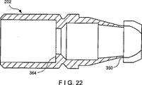
ヨーク204が近位側に動いてブシュ202に当接すると、カプセル・タブ306はヨーク204のカム面によってカプセル200の中心線から離れるよう屈曲する。その結果カプセル・タブ306は、図21、22にブシュ202の側面図および斜視図を示すように、対応するブシュのアンダーカット350にもはや係合しない。カプセル200および(シャフト部104に堅固に連結されている)ブシュ202はもはや連結されていないので、クリップ・アセンブリ106は、制御ワイヤ118の球140との連結によってのみ、シャフト部104から解除されないようになっている。詳細は後述するが、カプセルの様々な例示的な実施形態では、カプセル・タブ306を様々な構造に置き換えることができる。
As the
ヨーク204をブシュ202の遠位側ブシュ・ショルダー250に対して動かすことによってさらに、ワイヤ止め具360の遠位端(図12、16に示す)が近位側ブシュ・ショルダー364(図22に示す)付近に置かれるようになる。ワイヤ止め具360の遠位端に置かれたフレア状のフィンガー362は、図23により良く示すように、ブシュ202の中心内径を通過しながら圧縮されるが、近位側ブシュ・ショルダー364を通り過ぎた後、通常付勢されている開位置に戻る(図23に示す)。したがって、摺動スプール110をさらに遠位側に動かすことはできない。というのは、そのような動きは、ワイヤ止め具360のフィンガー362を近位側ブシュ・ショルダー364と係合させるからである。この特徴により、クリップ・アセンブリ106は、後述するように、球140が制御ワイヤ118から離れる前にブシュ202から離れて押し出されないようになっている。
Further, by moving the
ワイヤ止め具360は、従来の方法で制御ワイヤ118に取り付けられた第1のスロット状およびフレア状の端部を備えた管を含む。図23に示すように、スロットによってデバイスに可撓性がもたらされ、そのためブシュ202の中心管腔を簡単に通ることができる。スロットによってフレア状のフィンガー362が形成され、近位側ブシュ・ショルダー364に係合する。ワイヤ止め具360は生体適合性でありフィンガー362がブシュ202を通過した後に再度開くように十分な弾性を有する材料から作られる。例えば、本用途にはステンレス鋼を使用することができる。別の例示的な実施形態では、詳細は後述するが、ワイヤ止め具360をデバイスから省略することもできる。
The
上述の本発明の例示的な実施形態の1つの特徴は、使用者が、クリップ・アセンブリ106を展開し解除するとき触覚および聴覚フィードバックを受け取ることである。張力部材206をヨーク204から分離すると、ハンドル・アセンブリ102を保持している間に知覚可能な小さなクリック音および触感が生じる。したがって、摺動スプール110の軸方向位置の変更は、動きに対する抵抗の変化によって、動きの開始と停止によるクリック音および感覚によって、強化される。その結果、使用者は常にクリップ・アセンブリ106の状態を意識し、止血クリップ90が不正確な位置で不注意によって展開される可能性がより低く抑えられる。デバイスの操作に影響せずに、デバイスにおける雄型および雌型コネクタの順序を逆にするまたは変更することができることは、当業者には明らかであろう。
One feature of the exemplary embodiment of the invention described above is that the user receives tactile and auditory feedback when the
クリッピング・デバイス100の残りの部分を内視鏡から取り外す前に、クリップ・アセンブリ106が展開されていることを確認することは、使用者にとって有益であろう。止血クリップ90が一部しか展開されていないときに手術部位からクリッピング・デバイス100を取り外すと、治療する組織に損傷をもたらす恐れがある。したがって、ヨーク204を張力部材206から分離することによって生じる聴覚および触覚フィードバックを強化するために、大きな触覚フィードバックを組み込むことができる。図24は、クリップ・アセンブリ106がクリッピング・デバイス100の残りの部分から分離されてい
る状態を示す。上述の実施形態によれば、この第2の使用者フィードバックは、制御ワイヤ118を、所定の張力が加えられると端部球140から分離するように設計することによって得られる。言い換えると、制御ワイヤ118の球140は、あらかじめ設定された張力が加えられると降伏し制御ワイヤ118の本体から分離するように、機械的にプログラムされている。より小径の部分142のサイズは、プログラムされた降伏張力に達したときに使用者が摺動スプール110を近位側に動かし続けると、球140が先細部分144から脱着され、操作者に大きな触覚フィードバックを与えるように、選択することができる。
It may be beneficial for the user to ensure that the
球140が脱着されると、摺動スプール110はハンドル108の近位端で底面をあらわし、ハンドル・アセンブリ102の全ストロークが届くようになる。より小径の部分142を降伏させ球140を解除させるのに必要な張力は、値の範囲に応じて変えることができる。しかし、最良の結果を得るためには、雄型C字形断面214をヨーク204から分離するのに必要な張力よりも大きい力とするべきである。この条件が満たされない場合、クリップ・アセンブリ106が患者の組織上の定位置にロックされているがクリッピング・デバイス100から解除することはできないという状況が起きる可能性がある。この状況は避けるべきであることは明らかである。例示的な1実施形態では、球140を制御ワイヤ118の本体から分離するのに必要な張力は、制御ワイヤ118の遠位端で約44.482210ニュートン(10ポンド重)から88.9644ニュートン(20ポンド重)の範囲内である。上述したように、細長い可撓性シャフトに沿った損失があるので、使用者はこれよりかなり大きな力をハンドル本体102に加える必要がある場合がある。
When the
球140が制御ワイヤ118の残りの部分から分離されると、使用者はクリッピング・デバイス100の残りの部分を内視鏡から引き抜くことができる。このことが行われるとき、ヨーク204は、ばねおよびカプセル200の様々な部品、例えばカプセル・タブ306などの摩擦力によって、カプセル200内部に維持される。クリッピング・デバイス100を引き抜くときに内視鏡を損傷しないように、使用者はクリッピング・デバイス100を引き抜く前に、オーバーシース150をシャフト部104の残りの部分全体にわたって遠位側に動かすことができる。オーバーシース150がデバイス100の遠位端から不注意で摺動することがないように、オーバーシース把持部152の近位側のシャフト部104上に、シース止め156を配置することもできる。
Once the
クリッピング・デバイス100のいくつかの構成部品のより詳細な説明を以下に述べる。クリップ・アーム208の詳細を図18、19および20に示す。張力部材206の側面図および頂面図を図25、26に示す。ヨーク204の頂面図および側面図をそれぞれ図27および28に示す。クリップ・アーム208は、ニチノール、チタンまたはステンレス鋼などの生体適合性材料から形成することができる。400シリーズのステンレスまたは17−7PHなどの材料を使用することによって最大のばね特性を得ることができる。図に示すように、滴形のキー溝400が、張力部材206に形成された対応する滴形のキー溝402と対合するように、クリップ・アーム208に形成されている。この特徴により、これら2つの構成部品およびヨーク204の相対位置は、ほぼ一定に維持される。キー溝400の形状は様々とすることができる。例えば、キー溝400は卵形であっても楕円形であってもよい。クリップ・アーム208の中心部はばね部404を画成する。クリップ・アーム208の近位端252がヨーク204の張出し部254の下にあるとき、クリップ・アーム208は張力部材206上で枢動することができ、張力部材206はカプセル200によって制限されなくなったとき遠位端252を開形状に向かって付勢する。その結果、各クリップ・アーム208の近位端252は上向きに跳ね上がり、カプセル200のラッチ窓304に係合する。
A more detailed description of some components of the
クリップ・アーム208はまた、クリップに強度を追加しシステムの摩擦を軽減する半
径部分300を含む。半径部分300の半径はカプセル200の内径にほぼ一致し、カプセル200の内面を擦傷しないように滑らかな断面を有する。半径部分300とばね部404の間に与圧角度αが画成されている。与圧角度αは、2つの向かい合うクリップ・アーム208の間で、閉じているときそれらの遠位端に存在する干渉(与圧)の大きさを決定する。与圧角度αが大きいほど、クリップ・アーム208によってかかる係合力は大きくなる。しかし、この条件はまた、止血クリップ90が閉じているときに最大のシステム摩擦を生じる。クリップ・アーム208はまた、各遠位端に配設された噛合歯408も含む。例示的な実施形態では、アームが交換可能でありそれらと向き合うセットに滑らかに噛合するように、歯408は同一になっている。歯408は、約90度から135度の間であるノーズ角度βで配設されているが、他の適用例では上述の範囲よりも大きくまたは小さくすることもできる。
The
カプセル200の例示的な1実施形態を図14および15に示す。デバイスは、ブシュ202の対応する部品と対合して2つの構成部品を回転式に位置合わせするように設計された、整合キー溝500を含む。この例示的な実施形態では、カプセル・タブ306はブシュのアンダーカット350に係合するようにカプセル200の中心線に向かって屈曲することができる。係合は、ヨーク204が遠位側ブシュ・ショルダー内へ引き抜かれるまで、カプセル・アセンブリ200とクリッピング・デバイス100の残りの部分の間の一体性を維持する。カプセル張出し部502によって、展開されたクリップ・アーム208に追加のクランプ強度がもたらされる。これは、カプセル200の部分によって支持されない各クリップ・アーム208の部分の長さを短くすることによって達成される。カプセル張出し部502はクリップ・アーム208の平面にほぼ平行な平面上に延びているので、この特徴はクリップ・アーム208が捕捉することのできる組織の量には影響しない。
One exemplary embodiment of a
カプセル200の別の特徴は、クリップ・アセンブリ106の構成部品の位置合わせを助けるために使用することのできる、アセンブリ補助ポートを含む。屈曲補助具506は上述のように遠位側折り曲げタブ220が内向きに屈曲するとき、円滑な屈曲を容易にする。屈曲補助具506は、図に示すように、タブ220の折り曲げ線と位置合わせされた穴であるが、折り目、線状の刻み目、または他のタイプの応力集中装置とすることもできる。カプセル200は、どのような様々な生体適合性材料から形成することもできる。例えば、ステンレス鋼、チタンまたはニチノール、あるいはそれらのいずれかの組合せを使用することができる。カプセル200を形成するために、配置可能な要素を調節するために使用される高温での処置を用いて、PEEK(商標)またはUltem(商標)などの高強度ポリマーを使用することができる。
Another feature of the
本発明の別の例示的な実施形態を図30から33に示す。この実施形態では、クリップをデリバリー機構から解除することをさらに容易にするために、クリップ・カプセルおよび制御ワイヤ作動機構のいくつかの部品が変形されている。上述のように、クリップが患者の組織をクランプしているが展開機構から解除できないという状況を避けるために、クリップが展開後に制御ワイヤから完全に分離することを確認することは重要である。したがって、図30から33に示す例示的な実施形態は、クリップ・カプセルとブシュの間の機械的側面負荷を低減し、より円滑かつより確実なクリップの係合解除を容易にする、設計的特徴を組み込んでいる。 Another exemplary embodiment of the present invention is shown in FIGS. In this embodiment, several parts of the clip capsule and control wire actuation mechanism have been modified to make it easier to release the clip from the delivery mechanism. As noted above, it is important to ensure that the clip completely separates from the control wire after deployment to avoid the situation where the clip clamps the patient's tissue but cannot be released from the deployment mechanism. Accordingly, the exemplary embodiments shown in FIGS. 30-33 reduce the mechanical side load between the clip capsule and the bushing and facilitate the smoother and more reliable disengagement of the clip. Is incorporated.
より具体的には、例示的な本実施形態は、上述の実施形態のものより軸方向により短い、クリップ・カプセル804のインターフェース部816を組み込んでいる。例えば、インターフェース部816はこの実施形態では上述の実施形態のものより最大60%まで短くすることができる。インターフェース部816は、アセンブリに一時的に構造的強度を与えるように、ブシュ806に解除可能に連結するように適合されている。例示的な実施形態はまた、クリップ802およびカプセル804をブシュ806から分離するのを助け
るために使用することのできる制御ワイヤ810の別の遠位端も組み込んでいる。
More specifically, the present exemplary embodiment incorporates an
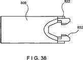
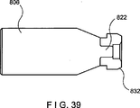
図34から37は、図30から33にも示す例示的な実施形態によるカプセル804をさらに詳細に示す。図38および39は、カプセル804と協働してクリップ802をデリバリー機構から円滑に解除するように適合された、対応するブシュ806を示す。本発明の例示的なカプセル804のいくつかの特徴は、上述の実施形態の特徴と同様であり、同じ機能を実行する。例えば、キー溝820は、ブシュ806の部品822と協働して2つの構成部品を回転式に位置合わせするように設計されている。ラッチ窓824もまた、上述したものと同じ機能を他の実施形態に対して実行し、クリップ802の近位端と協働する。
FIGS. 34-37 show the
本発明の実施形態の1つの特徴は、カプセル804をブシュ806に連結する様々な解除可能なロック機構を含む、より短縮されたインターフェース部816である。この実施形態では、「A字形」フレーム・タブ830がブシュのフック832と協働して、互いに取り付けられたカプセル804およびブシュ806を一時的に維持するように設計されている。図40から43は、ブシュ806に連結されているときのカプセル804の別の図を示す。デリバリー・デバイスのアセンブリ中、カプセル804をブシュ806上に動かし、次いで「A字形」フレーム・タブ830をブシュのフック832内へと屈曲することによって、2つの構成部品が取り付けられる。2つの構成部品を連結すると「A字形」フレーム・タブ830それぞれの内側遠位縁834が押し下げられ、ブシュのフック832の裏側でロックする。
One feature of embodiments of the present invention is a shortened
クリップ802を展開して組織をクランプし、次いで展開デバイス800から解除するとき、「A字形」フレーム・タブ830は、張力部材814が切り離された後でブシュ806のフック832から係合解除し、上述のように、ヨークのカム面が「A字形」フレーム・タブ830に係合する。解除シーケンスは、デバイスの前出の例示的な実施形態に関して上述したように、カプセル804内の内部構成部品が摺動スプール110およびハンドル108(図2)の動きに反応して動くことによって、実現される。
When the
クリップ・デリバリー・デバイス800の本実施形態に含まれる第2の特徴は、図30から33に示す制御ワイヤ810およびハイポ・チューブ900を含む。例示的な本実施形態では、ワイヤ止めは含まれておらず、制御ワイヤ810を使用して、クリップ802を展開した後でクリップ・デリバリー・デバイス800から離れるようにクリップ802を押し出すことができる。例えばより小径の部分904のプログラムされた破断(failure)によって、制御ワイヤ球902を制御ワイヤ810から分離した後で、制御ワイヤ810のこの追加的な機能を利用することができる。展開されたクリップ802を押し出すために制御ワイヤ810を使用することによって、クリップ802を患者の組織にクランプするとき、クリップ・デリバリー・デバイス800から完全に解除されるという、追加的な保証がもたらされる。
A second feature included in this embodiment of
本明細書に示す例示的な実施形態によれば、張力部材814を切り離した後で制御ワイヤ810を切断する前には、使用者がクリップ802を再度開こうと試みて制御ワイヤ810を遠位側に押す場合、クリップ802は制御ワイヤ810に連結されていながら組織に結合したままである。この時点で、クリップ・カプセル804の長手方向長さがより短いことによって、制御ワイヤ810を近位側に動かしてヨーク812をカプセル804の近位端から引き抜くことができる。次いで、ヨーク812の近位側の先細端をブシュ806の遠位側開口内へと引き寄せるように、ヨーク812を近位側に引き寄せながらブシュ806を遠位側に動かすことができる。ヨークは制御ワイヤ球902周りで回転していることがあるので、ヨーク812の近位側の先細端によって、ヨーク812がブシュ806と位置合わせし直すことが可能になる。ヨーク812をブシュ806と位置合わせし直し
た後、クリップ802を完全に解除するよう制御ワイヤ球902を制御ワイヤ810の近位部から分離するように、制御ワイヤ810をさらに近位側に引き寄せることができる。
In accordance with the exemplary embodiment shown herein, before disconnecting
クリップ解除デバイス800の例示的な実施形態の1つの操作方法を図30から33に示し、また図1および2も再び参照する。より小径の部分904が降伏し制御ワイヤ810が制御ワイヤ球902から分離した後、使用者は、制御ワイヤ810の(分離された)遠位端がクリップ802をクリップ・デリバリー・デバイス800から離れて遠位側に押し出すように、摺動スプール110をハンドル108に対して遠位側に前進させ、クリップ802がデリバリー・デバイス800から完全に分離されることをさらに保証する。次いで使用者はデリバリー・デバイス800を安全に取り外すことができる。
One method of operation of an exemplary embodiment of the
より小径の部分904が降伏した後、制御ワイヤ810の遠位端は粗面または鋭利であることがある。制御ワイヤ810の鋭利な端部による損傷の可能性を制限するために、保護シュラウド、例えばハイポ・チューブ900を制御ワイヤ810の遠位部の周りに配置する。例えばハイポ・チューブ900は制御ワイヤ810上で折り畳むことができ、カテーテルの内外で互いに長手方向に動くことができるようにしている。本発明の範囲から逸脱せずに、ハイポ・チューブ900を制御ワイヤ810に取り付ける他の方法を使用することもできることは、当業者には明らかであろう。制御ワイヤ810の鋭利な端部の周りに配置されたハイポ・チューブ900は、制御ワイヤ810を押し付けることのできる組織への外傷を最小限に抑えるための鈍い表面として作用する。さらに、ハイポ・チューブ90は、制御ワイヤ810を遠位側に動かして圧縮を受けるとき、より小径の部分がねじれに抵抗する際の助けとなるように、制御ワイヤ810のより小径の部分を硬化する。
After the
例示的な本実施形態では、制御ワイヤ810はクリップ・デリバリー・デバイス800に沿って長手方向に動くように開放される。したがって、デリバリー・デバイス800の様々な内部通路は、制御ワイヤ810の動きと干渉しないようなサイズとなっている。例えば、ブシュ・ショルダー906の内径は、ハイポ・チューブ900がブシュ・ショルダー906のリップを引っ掛けずに中を通過できるようになっている。この特徴によって、制御ワイヤ810を長手方向に動かすことおよびそれを使用して展開されたクリップ802を展開デバイス800から離れるよう長手方向に押すことがさらに容易になる。
In the exemplary embodiment,
したがって、上述のクリップ・デリバリー・デバイス800の例示的な実施形態は、クリップ802が標的組織上でクランプした後およびデリバリー・デバイス800を患者の体内から抜去する前に、クリップ802をより確実に円滑に分離することを促進する。より短い長手方向長さおよび「A字形」フレーム・ロッキング・タブを有するクリップ・カプセル804は、展開中に存在することのある側面負荷を低減し、標的組織をクランプすることによって確実な解除のさらなる確証を得た後で、クリップ802をデリバリー・デバイスから押し出すために制御ワイヤ810を使用することよって、カプセル804のブシュ806からの円滑な分離を促進することができる。
Thus, the exemplary embodiment of the
図25および26は張力部材206の別の詳細を示す。図に示すように滴形のキー溝402が、上述のように、クリップ・アーム208の滴形のキー溝400に係合するように設計されている。クリップ従動子平面508はクリップ・アーム208が開形状と閉形状の間で固定するように、支点を形成する形状である。張力部材206は、カプセル・アセンブリ106の遠位側の動きを止めるために、カプセル200の遠位側折り曲げタブ220に当接する遠位側止め面510を含む。一般に、カプセル200の内面に接触する張力部材206のすべての表面および縁は、好ましくはカプセル200の中で摺動的に嵌合するようにその内径とほぼ同様の半径を有する。張力部材206は生体適合性ポリマー、モノマーまたは熱硬化性物質で形成することができる。雄型C字形断面214の破断による解除は比較的脆性の材料を必要とし、また破断を伴わない降伏による解除はより軟性の材
料を必要とするので、張力部材206をヨーク204から解除するために選択される機構のタイプによって、使用する材料のタイプを決定することができる。
FIGS. 25 and 26 show another detail of the
ヨーク204の別の詳細を図27から29に示す。制御ワイヤ118がヨーク204に据え付けられているとき、不注意で制御ワイヤ・スロット600から外れることのないよう確実にすることが望ましい。したがって、本実施形態では、球空洞部602は球140が中を通るのに十分大きい直径を有し、球空洞部604は制御ワイヤ118が中を通るのには十分大きいが球140が中を通るのには十分でない大きさの直径を有する。例示的な実施形態に従って制御ワイヤ118をヨーク204に組み付けるために、ワイヤ140の近位端を球の底面が出るまで球空洞部602内に挿入し、次いで制御ワイヤ118が制御ワイヤ空洞部604内に据えられるまで回転し、それにより球140がさらに動くことを制限する。本実施形態によれば、ヨーク204はステンレス鋼などの生体適合性金属、またはUltem(商標)などの高強度ポリマーから作ることができる。
Additional details of the
本発明の実施形態によれば、クリッピング・デバイス100は様々な外科手術の要件に合わせるために規模を調整することができる。例示的な1実施形態では、クリッピング・デバイス100は、約0.2794センチメートル(0.110インチ)の直径の作業チャネルを有する内視鏡を通して嵌合するサイズにすることができる。例示的なブシュは、長さが約0.5588センチメートル(0.22インチ)、外径が約0.2159センチメートル(0.085インチ)とすることができる。カプセルの長さは約1.27センチメートル(0.5インチ)、外径は約0.2159センチメートル(0.085インチ)、厚さは0.00762センチメートル(0.003インチ)とすることができる。組み立てると、カプセル200およびブシュ202の剛性の長さは約1.5875センチメートル(0.625インチ)である。この長さは、長すぎるとアセンブリが可撓性の内視鏡の湾曲部を通過することができないので、重要である。例示的なクリッピング・デバイスでは、外側シースの内径は約0.2235センチメートル(0.088インチ)、外径は約0.2591センチメートル(0.102インチ)とすることができる。クリッピング・デバイスの全体的な長さは約406.4センチメートル(160インチ)、クリップ・アーム208の組織把持部の長さは約1.016センチメートル(0.4インチ)とすることができる。
In accordance with embodiments of the present invention,
本発明のいくつかの態様を以下に述べる。1態様では、本発明は、ハンドル・アセンブリ、ハンドル・アセンブリの遠位部に連結されたシャフト、シャフトの遠位部に解除可能に連結され、クリップ・アームおよびクリップ・アームと協働してクリップ・アセンブリの決定形状を示す第1の使用者フィードバックをもたらすカプセルを含むクリップ・アセンブリ、および球コネクタを備え、ハンドル・アセンブリから延び、シャフトに連結されたクリップ・アセンブリを維持するように球コネクタによってクリップ・アセンブリに連結された制御ワイヤを含む、止血クリップの展開のための装置を対象とし、クリップ・アセンブリがシャフトから分離されたことを示す第2の使用者フィードバックをもたらすように、球コネクタがクリップ・アセンブリから切り離し可能である。 Several aspects of the invention are described below. In one aspect, the present invention relates to a handle assembly, a shaft coupled to a distal portion of the handle assembly, a releasably coupled to a distal portion of the shaft, and a clip in cooperation with the clip arm and clip arm. A clip assembly including a capsule that provides a first user feedback indicative of the determined shape of the assembly, and a ball connector, extending from the handle assembly and maintained by the ball connector to maintain the clip assembly coupled to the shaft The ball connector is directed to an apparatus for deployment of a hemostatic clip that includes a control wire coupled to the clip assembly and provides a second user feedback indicating that the clip assembly has been separated from the shaft. It can be separated from the clip assembly.
装置は、シャフトおよびクリップ・アセンブリを覆う第1の位置とクリップ・アセンブリを露出する第2の位置の間で可動であるオーバーシースをさらに含む。オーバーシースは、オーバーシースが第2の位置へ動かないようにシャフト上で係合可能なオーバーシース止めを有する。 The apparatus further includes an oversheath that is movable between a first position that covers the shaft and clip assembly and a second position that exposes the clip assembly. The oversheath has an oversheath stop that is engageable on the shaft so that the oversheath does not move to the second position.
クリップ・アームは、制御ワイヤが近位側に動く間、第1の使用者フィードバックをもたらすように、カプセルの遠位端に係合する止めショルダーをさらに含む。決定形状は、制御ワイヤがそれを越えてさらに近位側に動くと制御ワイヤを反対に動かすことによってクリップ・アームが開位置に戻ることが不可能になる、制御ワイヤの位置を示す。 The clip arm further includes a stop shoulder that engages the distal end of the capsule to provide first user feedback while the control wire moves proximally. The determined shape indicates the position of the control wire where the clip arm cannot return to the open position by moving the control wire in the opposite direction as the control wire moves further proximally.
止血クリップの展開のための装置のカプセルは、球空洞部を含みカプセル内部で摺動可能であり、球空洞部に球コネクタを受けるヨーク、ヨークに解除可能に連結され、クリップ・アームに連結され、クリップ・アームを開形状に向かって付勢する張力部材をさらに含み、制御ワイヤが第1の使用者フィードバックがもたらされる位置を越えて近位側に動くと、張力部材がヨークから解除する。張力部材およびヨークは、雄型C字形断面部材および雌型C字形断面部材によって、互いに解除可能に連結されている。ヨークと張力部材の分離は、雄型C字形断面部材の破断および変形の一方によって起こる。 The capsule of the device for deployment of the hemostatic clip includes a spherical cavity and is slidable inside the capsule, the yoke receiving the spherical connector in the spherical cavity, releasably connected to the yoke, and connected to the clip arm , Further comprising a tension member that biases the clip arm toward the open shape, wherein the tension member releases from the yoke when the control wire moves proximally beyond the position where the first user feedback is provided. The tension member and the yoke are releasably connected to each other by a male C-shaped cross-section member and a female C-shaped cross-section member. Separation of the yoke and the tension member is caused by one of breaking and deformation of the male C-shaped cross-section member.
止血クリップの展開のための装置では、ヨークと張力部材の分離は、制御ワイヤ張力の張力が少なくとも所定の分離張力であるときに起こる。例えば、分離張力は少なくとも約17.7929ニュートン(4ポンド重)であり、あるいは約53.3786ニュートン(12ポンド重)未満とすることができる。ヨークと張力部材の分離は、張力部材およびクリップ・アームをカプセル内部で近位側に摺動することによって、クリップ・アームを閉形状にロックする。ヨークと張力部材の分離はまた、カプセルをシャフトのブシュから解除するようにヨークを近位側に動かすことを可能にする。ヨークを張力部材から分離する前に制御ワイヤを遠位側に動かすことによって、クリップ・アームが開形状へとカプセルから外へ遠位側に摺動する。 In the device for deployment of the hemostatic clip, separation of the yoke and the tension member occurs when the control wire tension tension is at least a predetermined separation tension. For example, the separation tension can be at least about 17.7929 Newtons (4 pounds weight) or less than about 53.3786 Newtons (12 pounds weight). Separation of the yoke and tension member locks the clip arm in a closed configuration by sliding the tension member and clip arm proximally within the capsule. The separation of the yoke and the tension member also allows the yoke to be moved proximally to release the capsule from the shaft bushing. By moving the control wire distally before separating the yoke from the tension member, the clip arm slides distally out of the capsule into the open configuration.
止血クリップの展開のための装置では、第1のフィードバックは触覚および聴覚フィードバックを含む。制御ワイヤは、球コネクタに隣接する、より小径の部分をさらに含み、より小径の部分は制御ワイヤの張力が所定の降伏張力に達すると降伏する。降伏張力は分離張力よりも大きく、約44.4822ニュートン(10ポンド重)と約88.9644ニュートン(20ポンド重)の間とすることができる。 In an apparatus for deployment of a hemostatic clip, the first feedback includes haptic and auditory feedback. The control wire further includes a smaller diameter portion adjacent to the ball connector that yields when the tension of the control wire reaches a predetermined yield tension. The yield tension is greater than the separation tension and can be between about 44.4822 Newtons (10 pounds weight) and about 88.9644 Newtons (20 pounds weight).
別の態様では、本発明は内視鏡を通して体内の部位に挿入可能なクリップ展開装置を対象とする。装置は近位端から遠位端へと延びる細長い部材、細長い部材の近位端からその遠位端へと延びる制御ワイヤ、細長い部材の遠位端に連結されたブシュ、およびブシュに解除可能に連結されたカプセルを含む。装置は、カプセル内部で遠位側開形状と近位側閉形状の間で摺動可能なクリップ・アーム、クリップ・アームとともに摺動可能であり、クリップ・アームを開形状に向かって付勢する張力部材、およびカプセル内部で摺動可能なヨークをさらに含み、ヨークの第1の端部が張力部材に解除可能に連結され、ヨークの第2の端部が制御ワイヤに連結され、制御ワイヤを遠位側に動かすことによってクリップ・アームが開形状へと摺動し、制御ワイヤを近位側に動かすことによってクリップ・アームが閉形状へと摺動する。 In another aspect, the present invention is directed to a clip deployment device that can be inserted through an endoscope into a body site. The device includes an elongated member extending from the proximal end to the distal end, a control wire extending from the proximal end of the elongated member to the distal end, a bushing coupled to the distal end of the elongated member, and releasable to the bushing Includes concatenated capsules. The device is slidable with a clip arm, clip arm slidable between a distal open shape and a proximal closed shape within the capsule, and biases the clip arm toward the open shape A tension member, and a yoke slidable within the capsule, wherein the first end of the yoke is releasably connected to the tension member, the second end of the yoke is connected to the control wire, and the control wire Moving the distal side slides the clip arm into the open shape, and moving the control wire proximally slides the clip arm into the closed shape.
上述した装置では、各クリップ・アームは半径部分を含み、カプセルは、クリップ・アームをカプセル内部で近位側に動かすと半径部分と協働してクリップ・アームを閉形状に維持する複数の張出し部を含む。各クリップ・アームはまた止めショルダーを含み、カプセルは、止めショルダーと協働して、クリップ・アームがカプセル内の選択された位置を通って近位側に動くことを示す第1の使用者フィードバックをもたらす、複数の遠位側折り曲げタブを含む。第1の使用者フィードバックは聴覚要素および触覚要素を含む。 In the apparatus described above, each clip arm includes a radius portion, and the capsule includes a plurality of overhangs that cooperate with the radius portion to maintain the clip arm in a closed shape as the clip arm is moved proximally within the capsule. Part. Each clip arm also includes a stop shoulder, and the capsule cooperates with the stop shoulder to provide first user feedback indicating that the clip arm moves proximally through a selected location within the capsule. Including a plurality of distal folding tabs. The first user feedback includes an auditory element and a tactile element.
制御ワイヤを、クリップ・アームが選択された位置に存在する点を越えて近位側に動かすことによって、ヨークの張力部材からの分離がもたらされる。ヨークを張力部材から分離することにより、クリップ・アームが開形状に戻ることが不可能になり、ヨークをさらに近位側に動かすことにより、カプセルをブシュから解除することが可能になる。 Moving the control wire proximally beyond the point where the clip arm is in the selected position provides separation from the tension member of the yoke. Separating the yoke from the tension member makes it impossible for the clip arm to return to the open shape, and moving the yoke further proximally allows the capsule to be released from the bushing.
上記の装置はさらに、ヨークと制御ワイヤの間にボール・ソケット型連結を含む。ボール・ソケット型連結は、制御ワイヤ上の張力が少なくとも所定の分離張力であるとき、制
御ワイヤの本体に脱着可能に連結された球を含み、球は、制御ワイヤの本体から分離するとき第2の使用者フィードバックをもたらす。
The apparatus further includes a ball and socket type connection between the yoke and the control wire. The ball and socket type connection includes a sphere removably connected to the body of the control wire when the tension on the control wire is at least a predetermined separation tension, the sphere being second when separated from the body of the control wire. Bring user feedback.
さらに別の態様では、本発明は、クリッピング・デバイスのシャフトを内視鏡の作業ルーメンを通して挿入するステップを含む止血クリッピングのための方法を対象としており、シャフトが複数のクリップ・アームを含むクリッピング・デバイスの遠位側クリッピング・アセンブリへと延び、制御ワイヤがシャフトを通りクリッピング・アセンブリからシャフトの近位端に連結されたハンドルへと延びる。方法はまた、制御ワイヤをシャフト内部で動かしてクリップ・アームを開形状と閉形状の間で動かすようにハンドル・アセンブリを操作するステップ、装置の決定形状を示す第1の使用者フィードバックを生成するステップ、およびクリッピング・アセンブリがシャフトから分離したことを示す第2の使用者フィードバックを生成するステップも含む。 In yet another aspect, the present invention is directed to a method for hemostatic clipping comprising the step of inserting a shaft of a clipping device through the working lumen of an endoscope, wherein the shaft comprises a plurality of clip arms. The device extends to the distal clipping assembly and a control wire extends through the shaft from the clipping assembly to a handle coupled to the proximal end of the shaft. The method also includes manipulating the handle assembly to move the control wire within the shaft to move the clip arm between an open shape and a closed shape, generating a first user feedback indicating the determined shape of the device. And generating a second user feedback indicating that the clipping assembly has separated from the shaft.
本発明による方法はさらに、シャフトおよびクリッピング・アセンブリを外側シースで覆うステップ、およびクリッピング・アセンブリを露出するように外側シースを近位側へ摺動するステップを含む。クリッピング・アセンブリはさらに、ヨークを摺動可能に収容するカプセル、およびクリップ・アームを開形状に向かって付勢する張力部材を含み、ヨークは制御ワイヤに連結され、張力部材に脱着可能に連結されている。 The method according to the invention further includes covering the shaft and clipping assembly with an outer sheath and sliding the outer sheath proximally to expose the clipping assembly. The clipping assembly further includes a capsule that slidably accommodates the yoke, and a tension member that biases the clip arm toward the open shape, the yoke being coupled to the control wire and removably coupled to the tension member. ing.
第1の使用者フィードバックを与えるステップは、クリップ・アームが近位側に動くことを止める抵抗力をもたらすステップ、およびハンドル・アセンブリの対応する動きに対する抵抗を増加するステップを含む。また、第1の使用者フィードバックの生成後に制御ワイヤに加えられる張力が少なくとも第1のあらかじめ選択された張力であるとき、ヨークを張力部材から分離するステップも含む。制御ワイヤに加えられる張力が少なくとも、第1のあらかじめ選択された張力よりも大きいものとすることのできる、第2のあらかじめ選択された張力であるとき、制御ワイヤのより小径の部分が降伏すると、第2の使用者フィードバックを生成する。 Providing first user feedback includes providing a resistance that stops the clip arm from moving proximally and increasing resistance to a corresponding movement of the handle assembly. Also included is separating the yoke from the tension member when the tension applied to the control wire after generation of the first user feedback is at least a first preselected tension. When the smaller diameter portion of the control wire yields when the tension applied to the control wire is at least a second preselected tension that can be greater than the first preselected tension, A second user feedback is generated.
以上、本発明を特定の例示的な実施形態を参照して説明した。特に形状、サイズ、材料および部品の配置の問題に関して、本発明の教示から逸脱せずに詳細での変更が可能であることを、当業者であれば理解するであろう。したがって、本発明の最も広い範囲から逸脱せずに様々な変形および変更を実施形態に行うことができる。したがって、明細書および図面は限定的な意味よりも例示的にとらえるべきである。 The present invention has been described above with reference to specific exemplary embodiments. Those skilled in the art will appreciate that changes in detail can be made without departing from the teachings of the present invention, particularly with respect to shape, size, material and component placement problems. Accordingly, various modifications and changes can be made to the embodiments without departing from the broadest scope of the invention. The specification and drawings are, accordingly, to be regarded in an illustrative rather than a restrictive sense.
本発明を特定の例示的な実施形態を参照して説明した。特に形状、サイズ、材料および部品の配置の問題に関して、本発明の教示から逸脱せずに詳細での変更が可能であることを、当業者であれば理解するであろう。例えば、ヨーク、張力部材およびブシュの様々な形状を使用することができ、クリップ・アームと制御ワイヤの様々な取付け法を採用することができる。したがって、添付の特許請求の範囲に述べられている本発明の最も広い範囲から逸脱せずに様々な変形および変更を実施形態に行うことができる。したがって、明細書および図面は限定的な意味よりも例示的にとらえるべきである。 The invention has been described with reference to specific exemplary embodiments. Those skilled in the art will appreciate that changes in detail can be made without departing from the teachings of the present invention, particularly with respect to shape, size, material and component placement problems. For example, various shapes of yokes, tension members and bushings can be used, and various attachment methods of clip arms and control wires can be employed. Accordingly, various modifications and changes can be made to the embodiments without departing from the broadest scope of the invention as set forth in the appended claims. The specification and drawings are, accordingly, to be regarded in an illustrative rather than a restrictive sense.
Claims (31)
同ハンドル・アセンブリの遠位部に連結されたシャフトと、
該シャフトの遠位部に解除可能に連結されたクリップ・アセンブリと、同クリップ・アセンブリは、2つのクリップ・アームと、同クリップ・アームと協働して該クリップ・アセンブリの決定形状を示す第1の使用者フィードバックをもたらすカプセルとを有することと、
球コネクタを含み、該シャフトに連結された該クリップ・アセンブリを維持するように、該ハンドル・アセンブリから延び、該球コネクタによって該クリップ・アセンブリに連結された制御ワイヤとからなり、該球コネクタは、該クリップ・アセンブリから分離可能であり、該クリップ・アセンブリの該シャフトからの分離を示す第2の使用者フィードバックをもたらす止血クリップの展開のための装置。A handle assembly;
A shaft coupled to the distal portion of the handle assembly;
A clip assembly releasably connected to a distal portion of the shaft, the clip assembly cooperating with the two clip arms and defining the shape of the clip assembly; Having a capsule that provides first user feedback;
A ball connector including a control wire extending from the handle assembly and connected to the clip assembly by the ball connector so as to maintain the clip assembly connected to the shaft. , can be separated from the clip assembly, apparatus for deployment of a hemostatic clip to bring the second user feedback indicating separation from the shaft of the clip assembly.
前記球コネクタを受ける球空洞部を含み、前記カプセル内部で摺動可能なヨークと、
該ヨークに解除可能に連結され、前記クリップ・アームに連結され、前記クリップ・アームを開形状に向かって付勢する張力部材とをさらに含み、第1の使用者フィードバックが得られる位置を越えて近位側に制御ワイヤが移動されると、該張力部材が該ヨークから解除する請求項1に記載の装置。The capsule is
A sphere cavity for receiving the sphere connector, and a yoke slidable within the capsule;
A tension member coupled releasably to the yoke, coupled to the clip arm, and biasing the clip arm toward an open shape, beyond a position where a first user feedback is obtained. The apparatus of claim 1, wherein the tension member releases from the yoke when the control wire is moved proximally.
クリップを該カプセル内へと近位側に引き寄せるとクリップのアームが閉位置へと互いに引き寄せられ、クリップを該カプセル内部で所定の位置へと引き寄せると少なくとも1つのアームの当接面が該カプセルの対応する表面に接触し、クリップが閉じたことを示す第1の使用者フィードバックがもたらされるように、該カプセル内部に摺動可能に設置されたクリップと、 Pulling the clip proximally into the capsule causes the arms of the clip to be pulled together into the closed position, and pulling the clip into place within the capsule causes the abutment surface of at least one arm to move toward the capsule. A clip slidably disposed within the capsule so as to contact a corresponding surface and provide first user feedback indicating that the clip is closed;
クリップ・アームに連結され、該クリップ・アームを開形状、組織を受ける形状に向かって付勢する張力部材と、 A tension member connected to the clip arm and biasing the clip arm toward an open shape, a shape to receive tissue;
該カプセル内部で摺動可能に受けられ、該張力部材に解除可能に連結され、デリバリー・デバイスに連結されたクリップ・アセンブリを維持するようにデリバリー・デバイスの制御要素の球コネクタを受ける球空洞部を含むヨークとからなり、該制御要素が該ヨークを該デリバリー・デバイスから切り離し、第2の使用者フィードバックをもたらすように脆弱であり、該ヨークを該張力部材から解除することによって第3の使用者フィードバックをもたらす、デリバリー・デバイスに設置するための止血クリップ・アセンブリ。 A spherical cavity that is slidably received within the capsule, releasably coupled to the tension member, and receiving a spherical connector of a control element of the delivery device to maintain a clip assembly coupled to the delivery device A third use by releasing the yoke from the tension member, the control element being fragile to disconnect the yoke from the delivery device and providing a second user feedback Hemostatic clip assembly for installation on a delivery device that provides feedback to the person.
Applications Claiming Priority (7)
| Application Number | Priority Date | Filing Date | Title |
|---|---|---|---|
| US10/674,512 | 2003-09-30 | ||
| US10/674,512 US7494461B2 (en) | 2003-09-30 | 2003-09-30 | Through the scope tension member release clip |
| US56841804P | 2004-05-05 | 2004-05-05 | |
| US60/568,418 | 2004-05-05 | ||
| PCT/US2004/032444 WO2005032381A2 (en) | 2003-09-30 | 2004-09-30 | Through the scope tension member release clip |
| US10/955,624 US7452327B2 (en) | 2003-09-30 | 2004-09-30 | Through the scope tension member release clip |
| US10/955,624 | 2004-09-30 |
Publications (2)
| Publication Number | Publication Date |
|---|---|
| JP2007507307A JP2007507307A (en) | 2007-03-29 |
| JP4921173B2 true JP4921173B2 (en) | 2012-04-25 |
Family
ID=34426925
Family Applications (1)
| Application Number | Title | Priority Date | Filing Date |
|---|---|---|---|
| JP2006534166A Active JP4921173B2 (en) | 2003-09-30 | 2004-09-30 | Hemostatic clip deployment device and hemostatic clip assembly |
Country Status (6)
| Country | Link |
|---|---|
| US (6) | US7452327B2 (en) |
| EP (3) | EP3443915B2 (en) |
| JP (1) | JP4921173B2 (en) |
| AU (1) | AU2004277994B2 (en) |
| CA (1) | CA2539979C (en) |
| WO (1) | WO2005032381A2 (en) |
Cited By (5)
| Publication number | Priority date | Publication date | Assignee | Title |
|---|---|---|---|---|
| US11013517B2 (en) | 2017-06-21 | 2021-05-25 | Fujifilm Corporation | Clip treatment tool |
| US11141167B2 (en) | 2017-06-21 | 2021-10-12 | Fujifilm Corporation | Clip treatment tool |
| US11141166B2 (en) | 2017-03-22 | 2021-10-12 | Fujifilm Corporation | Clip treatment tool |
| US11284904B2 (en) | 2017-06-21 | 2022-03-29 | Fujifilm Corporation | Clip treatment tool |
| US11589875B1 (en) | 2021-08-25 | 2023-02-28 | GastroLogic LLC | Endoscopic clip apparatus and methods |
Families Citing this family (238)
| Publication number | Priority date | Publication date | Assignee | Title |
|---|---|---|---|---|
| US6695867B2 (en) | 2002-02-21 | 2004-02-24 | Integrated Vascular Systems, Inc. | Plunger apparatus and methods for delivering a closure device |
| US8690910B2 (en) | 2000-12-07 | 2014-04-08 | Integrated Vascular Systems, Inc. | Closure device and methods for making and using them |
| US7094245B2 (en) * | 2001-10-05 | 2006-08-22 | Scimed Life Systems, Inc. | Device and method for through the scope endoscopic hemostatic clipping |
| US8398656B2 (en) | 2003-01-30 | 2013-03-19 | Integrated Vascular Systems, Inc. | Clip applier and methods of use |
| EP1608272B1 (en) | 2003-03-11 | 2017-01-25 | Covidien LP | Clip applying apparatus with angled jaw |
| US7494461B2 (en) * | 2003-09-30 | 2009-02-24 | Boston Scientific Scimed, Inc. | Through the scope tension member release clip |
| US9763668B2 (en) | 2004-10-08 | 2017-09-19 | Covidien Lp | Endoscopic surgical clip applier |
| ES2547214T3 (en) | 2004-10-08 | 2015-10-02 | Covidien Lp | An endoscopic clip or surgical clip applicator |
| US7819886B2 (en) | 2004-10-08 | 2010-10-26 | Tyco Healthcare Group Lp | Endoscopic surgical clip applier |
| US8920438B2 (en) | 2004-10-08 | 2014-12-30 | Covidien Lp | Apparatus for applying surgical clips |
| US8409222B2 (en) | 2004-10-08 | 2013-04-02 | Covidien Lp | Endoscopic surgical clip applier |
| JP4758173B2 (en) * | 2004-12-24 | 2011-08-24 | オリンパス株式会社 | Ligation device |
| US8313497B2 (en) | 2005-07-01 | 2012-11-20 | Abbott Laboratories | Clip applier and methods of use |
| US7866525B2 (en) * | 2006-10-06 | 2011-01-11 | Tyco Healthcare Group Lp | Surgical instrument having a plastic surface |
| EP2314232B1 (en) | 2006-10-17 | 2015-03-25 | Covidien LP | Apparatus for applying surgical clips |
| US7655004B2 (en) | 2007-02-15 | 2010-02-02 | Ethicon Endo-Surgery, Inc. | Electroporation ablation apparatus, system, and method |
| EP3189796B1 (en) | 2007-03-26 | 2019-09-25 | Covidien LP | Endoscopic surgical clip applier |
| CN102327136B (en) | 2007-04-11 | 2014-04-23 | 柯惠Lp公司 | Surgical clip applier |
| US8075572B2 (en) | 2007-04-26 | 2011-12-13 | Ethicon Endo-Surgery, Inc. | Surgical suturing apparatus |
| US8133242B1 (en) | 2007-04-27 | 2012-03-13 | Q-Tech Medical Incorporated | Image-guided extraluminal occlusion |
| US8162959B2 (en) * | 2007-05-03 | 2012-04-24 | Boston Scientific Scimed, Inc. | Single stage hemostasis clipping device |
| US8579897B2 (en) | 2007-11-21 | 2013-11-12 | Ethicon Endo-Surgery, Inc. | Bipolar forceps |
| US8262655B2 (en) | 2007-11-21 | 2012-09-11 | Ethicon Endo-Surgery, Inc. | Bipolar forceps |
| US8568410B2 (en) | 2007-08-31 | 2013-10-29 | Ethicon Endo-Surgery, Inc. | Electrical ablation surgical instruments |
| JP5006753B2 (en) * | 2007-10-17 | 2012-08-22 | Hoya株式会社 | Endoscopic clip device |
| US8480657B2 (en) | 2007-10-31 | 2013-07-09 | Ethicon Endo-Surgery, Inc. | Detachable distal overtube section and methods for forming a sealable opening in the wall of an organ |
| US20090112059A1 (en) | 2007-10-31 | 2009-04-30 | Nobis Rudolph H | Apparatus and methods for closing a gastrotomy |
| WO2009070743A1 (en) | 2007-11-26 | 2009-06-04 | Eastern Virginia Medical School | Magnaretractor system and method |
| US20090187198A1 (en) * | 2008-01-22 | 2009-07-23 | Barry Weitzner | Resolution Clip |
| US8262680B2 (en) | 2008-03-10 | 2012-09-11 | Ethicon Endo-Surgery, Inc. | Anastomotic device |
| US9282965B2 (en) | 2008-05-16 | 2016-03-15 | Abbott Laboratories | Apparatus and methods for engaging tissue |
| US8070759B2 (en) | 2008-05-30 | 2011-12-06 | Ethicon Endo-Surgery, Inc. | Surgical fastening device |
| US8114072B2 (en) | 2008-05-30 | 2012-02-14 | Ethicon Endo-Surgery, Inc. | Electrical ablation device |
| US8652150B2 (en) | 2008-05-30 | 2014-02-18 | Ethicon Endo-Surgery, Inc. | Multifunction surgical device |
| US8771260B2 (en) | 2008-05-30 | 2014-07-08 | Ethicon Endo-Surgery, Inc. | Actuating and articulating surgical device |
| US8317806B2 (en) | 2008-05-30 | 2012-11-27 | Ethicon Endo-Surgery, Inc. | Endoscopic suturing tension controlling and indication devices |
| US8679003B2 (en) | 2008-05-30 | 2014-03-25 | Ethicon Endo-Surgery, Inc. | Surgical device and endoscope including same |
| US8906035B2 (en) | 2008-06-04 | 2014-12-09 | Ethicon Endo-Surgery, Inc. | Endoscopic drop off bag |
| US8403926B2 (en) | 2008-06-05 | 2013-03-26 | Ethicon Endo-Surgery, Inc. | Manually articulating devices |
| EP2630923B1 (en) | 2008-06-19 | 2015-02-11 | Boston Scientific Scimed, Inc. | Hemostatic clipping devices |
| US8361112B2 (en) | 2008-06-27 | 2013-01-29 | Ethicon Endo-Surgery, Inc. | Surgical suture arrangement |
| US8888792B2 (en) | 2008-07-14 | 2014-11-18 | Ethicon Endo-Surgery, Inc. | Tissue apposition clip application devices and methods |
| US8262563B2 (en) | 2008-07-14 | 2012-09-11 | Ethicon Endo-Surgery, Inc. | Endoscopic translumenal articulatable steerable overtube |
| US8211125B2 (en) | 2008-08-15 | 2012-07-03 | Ethicon Endo-Surgery, Inc. | Sterile appliance delivery device for endoscopic procedures |
| US8056565B2 (en) | 2008-08-25 | 2011-11-15 | Tyco Healthcare Group Lp | Surgical clip applier and method of assembly |
| US8529563B2 (en) | 2008-08-25 | 2013-09-10 | Ethicon Endo-Surgery, Inc. | Electrical ablation devices |
| US8465502B2 (en) | 2008-08-25 | 2013-06-18 | Covidien Lp | Surgical clip applier and method of assembly |
| US20110208212A1 (en) | 2010-02-19 | 2011-08-25 | Zergiebel Earl M | Surgical clip applier |
| US8241204B2 (en) | 2008-08-29 | 2012-08-14 | Ethicon Endo-Surgery, Inc. | Articulating end cap |
| US8409223B2 (en) | 2008-08-29 | 2013-04-02 | Covidien Lp | Endoscopic surgical clip applier with clip retention |
| US8585717B2 (en) | 2008-08-29 | 2013-11-19 | Covidien Lp | Single stroke endoscopic surgical clip applier |
| US9358015B2 (en) | 2008-08-29 | 2016-06-07 | Covidien Lp | Endoscopic surgical clip applier with wedge plate |
| US8267944B2 (en) | 2008-08-29 | 2012-09-18 | Tyco Healthcare Group Lp | Endoscopic surgical clip applier with lock out |
| US8480689B2 (en) | 2008-09-02 | 2013-07-09 | Ethicon Endo-Surgery, Inc. | Suturing device |
| US8409200B2 (en) | 2008-09-03 | 2013-04-02 | Ethicon Endo-Surgery, Inc. | Surgical grasping device |
| US8114119B2 (en) | 2008-09-09 | 2012-02-14 | Ethicon Endo-Surgery, Inc. | Surgical grasping device |
| US8337394B2 (en) | 2008-10-01 | 2012-12-25 | Ethicon Endo-Surgery, Inc. | Overtube with expandable tip |
| US8157834B2 (en) | 2008-11-25 | 2012-04-17 | Ethicon Endo-Surgery, Inc. | Rotational coupling device for surgical instrument with flexible actuators |
| EP2373224A1 (en) * | 2008-12-09 | 2011-10-12 | Wilson-Cook Medical Inc. | Apparatus and methods for controlled release of tacking devices |
| US8172772B2 (en) | 2008-12-11 | 2012-05-08 | Ethicon Endo-Surgery, Inc. | Specimen retrieval device |
| US9486191B2 (en) | 2009-01-09 | 2016-11-08 | Abbott Vascular, Inc. | Closure devices |
| US8828031B2 (en) | 2009-01-12 | 2014-09-09 | Ethicon Endo-Surgery, Inc. | Apparatus for forming an anastomosis |
| US8361066B2 (en) | 2009-01-12 | 2013-01-29 | Ethicon Endo-Surgery, Inc. | Electrical ablation devices |
| US8252057B2 (en) | 2009-01-30 | 2012-08-28 | Ethicon Endo-Surgery, Inc. | Surgical access device |
| US9226772B2 (en) | 2009-01-30 | 2016-01-05 | Ethicon Endo-Surgery, Inc. | Surgical device |
| DE102009007205A1 (en) * | 2009-02-03 | 2010-08-05 | Aesculap Ag | Surgical instrument |
| CL2009000279A1 (en) * | 2009-02-06 | 2009-08-14 | Biotech Innovations Ltda | Remote guidance and traction system for mini-invasive surgery, comprising: at least one surgical and removable endopinza with hooking means and a portion of ferro-magnaetic material, a cylindrical introduction guide, a detachment mechanism, and at least a means of remote traction with magnet. |
| US8894669B2 (en) | 2009-05-12 | 2014-11-25 | Ethicon, Inc. | Surgical fasteners, applicator instruments, and methods for deploying surgical fasteners |
| EP2467069A1 (en) * | 2009-08-19 | 2012-06-27 | Boston Scientific Scimed, Inc. | Multifunctional core for two-piece hemostasis clip |
| US9005219B2 (en) | 2009-08-19 | 2015-04-14 | Boston Scientific Scimed, Inc. | Multifunctional core for two-piece hemostasis clip |
| US8734469B2 (en) | 2009-10-13 | 2014-05-27 | Covidien Lp | Suture clip applier |
| US20110098704A1 (en) | 2009-10-28 | 2011-04-28 | Ethicon Endo-Surgery, Inc. | Electrical ablation devices |
| US8608652B2 (en) | 2009-11-05 | 2013-12-17 | Ethicon Endo-Surgery, Inc. | Vaginal entry surgical devices, kit, system, and method |
| US9186136B2 (en) | 2009-12-09 | 2015-11-17 | Covidien Lp | Surgical clip applier |
| US8545486B2 (en) | 2009-12-15 | 2013-10-01 | Covidien Lp | Surgical clip applier |
| US8496574B2 (en) | 2009-12-17 | 2013-07-30 | Ethicon Endo-Surgery, Inc. | Selectively positionable camera for surgical guide tube assembly |
| US8353487B2 (en) | 2009-12-17 | 2013-01-15 | Ethicon Endo-Surgery, Inc. | User interface support devices for endoscopic surgical instruments |
| US9028483B2 (en) | 2009-12-18 | 2015-05-12 | Ethicon Endo-Surgery, Inc. | Surgical instrument comprising an electrode |
| US8506564B2 (en) | 2009-12-18 | 2013-08-13 | Ethicon Endo-Surgery, Inc. | Surgical instrument comprising an electrode |
| WO2011087723A1 (en) | 2009-12-22 | 2011-07-21 | Wilson-Cook Medical, Inc. | Medical devices with detachable pivotable jaws |
| US8545519B2 (en) | 2009-12-22 | 2013-10-01 | Cook Medical Technologies Llc | Medical devices with detachable pivotable jaws |
| US8939997B2 (en) | 2010-10-11 | 2015-01-27 | Cook Medical Technologies Llc | Medical devices with detachable pivotable jaws |
| US10010336B2 (en) | 2009-12-22 | 2018-07-03 | Cook Medical Technologies, Inc. | Medical devices with detachable pivotable jaws |
| US9005198B2 (en) | 2010-01-29 | 2015-04-14 | Ethicon Endo-Surgery, Inc. | Surgical instrument comprising an electrode |
| US8403945B2 (en) | 2010-02-25 | 2013-03-26 | Covidien Lp | Articulating endoscopic surgical clip applier |
| US8211121B1 (en) | 2010-03-06 | 2012-07-03 | Q-Tech Medical Incorporated | Methods and apparatus for image-guided extraluminal occlusion using clamping jaws |
| US9044240B2 (en) * | 2010-03-10 | 2015-06-02 | Boston Scientific Scimed, Inc. | Hemostasis clip |
| JP5486983B2 (en) * | 2010-03-29 | 2014-05-07 | 富士フイルム株式会社 | Ligation device |
| US8403946B2 (en) | 2010-07-28 | 2013-03-26 | Covidien Lp | Articulating clip applier cartridge |
| US8968337B2 (en) | 2010-07-28 | 2015-03-03 | Covidien Lp | Articulating clip applier |
| US9743933B2 (en) | 2010-09-14 | 2017-08-29 | Boston Scientific Scimed, Inc. | Release mechanism for hemostasis clip |
| CN103124530B (en) | 2010-09-22 | 2016-03-30 | 富士胶片株式会社 | Apparatus for ligating and the clip unit used in this apparatus for ligating |
| EP2627268B8 (en) | 2010-10-11 | 2017-07-26 | Cook Medical Technologies LLC | Medical devices with detachable pivotable jaws |
| AU2015200218B2 (en) * | 2010-10-11 | 2017-06-01 | Cook Medical Technologies Llc | Medical devices with detachable pivotable jaws |
| WO2012051188A2 (en) | 2010-10-11 | 2012-04-19 | Cook Medical Technologies Llc | Medical devices with detachable pivotable jaws |
| US9011464B2 (en) | 2010-11-02 | 2015-04-21 | Covidien Lp | Self-centering clip and jaw |
| AU2011343659B2 (en) | 2010-12-15 | 2015-01-15 | Cook Medical Technologies Llc | Medical devices with detachable pivotable jaws |
| US10092291B2 (en) | 2011-01-25 | 2018-10-09 | Ethicon Endo-Surgery, Inc. | Surgical instrument with selectively rigidizable features |
| US9186153B2 (en) | 2011-01-31 | 2015-11-17 | Covidien Lp | Locking cam driver and jaw assembly for clip applier |
| US9233241B2 (en) | 2011-02-28 | 2016-01-12 | Ethicon Endo-Surgery, Inc. | Electrical ablation devices and methods |
| US9254169B2 (en) | 2011-02-28 | 2016-02-09 | Ethicon Endo-Surgery, Inc. | Electrical ablation devices and methods |
| US9314620B2 (en) | 2011-02-28 | 2016-04-19 | Ethicon Endo-Surgery, Inc. | Electrical ablation devices and methods |
| US9049987B2 (en) | 2011-03-17 | 2015-06-09 | Ethicon Endo-Surgery, Inc. | Hand held surgical device for manipulating an internal magnet assembly within a patient |
| US8397972B2 (en) | 2011-03-18 | 2013-03-19 | Covidien Lp | Shipping wedge with lockout |
| US9775623B2 (en) | 2011-04-29 | 2017-10-03 | Covidien Lp | Surgical clip applier including clip relief feature |
| WO2013067662A1 (en) * | 2011-11-11 | 2013-05-16 | Zhu Jian | Clamping or ligating device |
| US20130131697A1 (en) | 2011-11-21 | 2013-05-23 | Covidien Lp | Surgical clip applier |
| US9364239B2 (en) | 2011-12-19 | 2016-06-14 | Covidien Lp | Jaw closure mechanism for a surgical clip applier |
| US8984720B2 (en) * | 2011-12-28 | 2015-03-24 | Pioneer Surgical Technology, Inc. | Tensioning instrument and method |
| US9364216B2 (en) | 2011-12-29 | 2016-06-14 | Covidien Lp | Surgical clip applier with integrated clip counter |
| US8986199B2 (en) | 2012-02-17 | 2015-03-24 | Ethicon Endo-Surgery, Inc. | Apparatus and methods for cleaning the lens of an endoscope |
| US9408610B2 (en) | 2012-05-04 | 2016-08-09 | Covidien Lp | Surgical clip applier with dissector |
| US9427255B2 (en) | 2012-05-14 | 2016-08-30 | Ethicon Endo-Surgery, Inc. | Apparatus for introducing a steerable camera assembly into a patient |
| US9532787B2 (en) | 2012-05-31 | 2017-01-03 | Covidien Lp | Endoscopic clip applier |
| US9078662B2 (en) | 2012-07-03 | 2015-07-14 | Ethicon Endo-Surgery, Inc. | Endoscopic cap electrode and method for using the same |
| US9545290B2 (en) | 2012-07-30 | 2017-01-17 | Ethicon Endo-Surgery, Inc. | Needle probe guide |
| US9572623B2 (en) | 2012-08-02 | 2017-02-21 | Ethicon Endo-Surgery, Inc. | Reusable electrode and disposable sheath |
| US10314649B2 (en) | 2012-08-02 | 2019-06-11 | Ethicon Endo-Surgery, Inc. | Flexible expandable electrode and method of intraluminal delivery of pulsed power |
| US9277957B2 (en) | 2012-08-15 | 2016-03-08 | Ethicon Endo-Surgery, Inc. | Electrosurgical devices and methods |
| US9561064B2 (en) | 2012-11-21 | 2017-02-07 | Pioneer Surgical Technology, Inc. | Bone plate system and method |
| US10765465B2 (en) | 2012-11-21 | 2020-09-08 | A&E Advanced Closure Systems, Llc | Tensioning instrument |
| US9364209B2 (en) | 2012-12-21 | 2016-06-14 | Abbott Cardiovascular Systems, Inc. | Articulating suturing device |
| US9113892B2 (en) | 2013-01-08 | 2015-08-25 | Covidien Lp | Surgical clip applier |
| US9968362B2 (en) | 2013-01-08 | 2018-05-15 | Covidien Lp | Surgical clip applier |
| US9750500B2 (en) | 2013-01-18 | 2017-09-05 | Covidien Lp | Surgical clip applier |
| US10098527B2 (en) | 2013-02-27 | 2018-10-16 | Ethidcon Endo-Surgery, Inc. | System for performing a minimally invasive surgical procedure |
| US8764769B1 (en) | 2013-03-12 | 2014-07-01 | Levita Magnetics International Corp. | Grasper with magnetically-controlled positioning |
| WO2014159023A1 (en) | 2013-03-14 | 2014-10-02 | Levita Magnetics International Corp. | Magnetic control assemblies and systems therefor |
| CN103315792B (en) * | 2013-06-29 | 2015-06-03 | 安瑞医疗器械(杭州)有限公司 | Clamping device and jaw part thereof |
| CA2918098A1 (en) * | 2013-08-20 | 2015-02-26 | Boston Scientific Scimed, Inc. | Braided hemostasis shaft for improved torsional response |
| US9775624B2 (en) | 2013-08-27 | 2017-10-03 | Covidien Lp | Surgical clip applier |
| US9999454B2 (en) | 2013-12-05 | 2018-06-19 | A&E Advanced Closure Systems, Llc | Bone plate system and method |
| WO2015112645A1 (en) | 2014-01-21 | 2015-07-30 | Levita Magnetics International Corp. | Laparoscopic graspers and systems therefor |
| WO2015157116A1 (en) * | 2014-04-08 | 2015-10-15 | Boston Scientific Scimed, Inc. | Endoscopic closure device |
| US10314635B2 (en) | 2014-05-28 | 2019-06-11 | A&E Advanced Closure Systems, Llc | Tensioning instruments |
| JP6572229B2 (en) * | 2014-10-24 | 2019-09-04 | 株式会社カネカ | Endoscopic clip device |
| US10702278B2 (en) | 2014-12-02 | 2020-07-07 | Covidien Lp | Laparoscopic surgical ligation clip applier |
| CN107205817B (en) * | 2014-12-04 | 2020-04-03 | 爱德华兹生命科学公司 | Percutaneous clamp for repairing heart valve |
| US9931124B2 (en) | 2015-01-07 | 2018-04-03 | Covidien Lp | Reposable clip applier |
| US10368876B2 (en) | 2015-01-15 | 2019-08-06 | Covidien Lp | Endoscopic reposable surgical clip applier |
| US10292712B2 (en) | 2015-01-28 | 2019-05-21 | Covidien Lp | Surgical clip applier with integrated cutter |
| US11123204B2 (en) | 2015-02-06 | 2021-09-21 | Boston Scientific Scimed, Inc. | Anti-migration stent |
| JP2018507089A (en) * | 2015-03-04 | 2018-03-15 | エンドギア エルエルシー | Endoscopic clip |
| US10159491B2 (en) | 2015-03-10 | 2018-12-25 | Covidien Lp | Endoscopic reposable surgical clip applier |
| ES2895900T3 (en) | 2015-04-13 | 2022-02-23 | Levita Magnetics Int Corp | Magnetically controlled location handle |
| EP3967244A1 (en) | 2015-04-13 | 2022-03-16 | Levita Magnetics International Corp. | Retractor devices |
| EP3302306B1 (en) | 2015-05-27 | 2020-07-22 | Coloplast A/S | Grasping tool |
| US20190231352A1 (en) * | 2015-10-23 | 2019-08-01 | Kaneka Corporation | Medical clip |
| JP6626197B2 (en) | 2015-11-03 | 2019-12-25 | コヴィディエン リミテッド パートナーシップ | Endoscopic surgical clip applier |
| AU2015414380B2 (en) | 2015-11-10 | 2020-10-15 | Covidien Lp | Endoscopic reposable surgical clip applier |
| CA2999906A1 (en) | 2015-11-10 | 2017-05-18 | Covidien Lp | Endoscopic reposable surgical clip applier |
| US10390831B2 (en) | 2015-11-10 | 2019-08-27 | Covidien Lp | Endoscopic reposable surgical clip applier |
| AU2016364950B2 (en) | 2015-12-03 | 2019-05-16 | Boston Scientific Scimed, Inc. | Electrocautery hemostasis clip |
| CN108472044B (en) | 2016-01-11 | 2021-04-16 | 柯惠有限合伙公司 | Operation clip applier with endoscope capable of being placed |
| WO2017124217A1 (en) | 2016-01-18 | 2017-07-27 | Covidien Lp | Endoscopic surgical clip applier |
| AU2017210022B2 (en) | 2016-01-22 | 2021-05-13 | A&E Advanced Closure Systems, Llc | Bone plate having a connector and a connector for a surgical loop |
| CA2958160A1 (en) | 2016-02-24 | 2017-08-24 | Covidien Lp | Endoscopic reposable surgical clip applier |
| WO2017156618A1 (en) | 2016-03-15 | 2017-09-21 | Titan Medical Inc. | Apparatus for removably receiving an end effector for performing surgical operations |
| EP4324410A3 (en) * | 2016-05-09 | 2024-04-17 | Boston Scientific Scimed, Inc. | Closure device with fixed jaw hook |
| US10485600B2 (en) | 2016-07-29 | 2019-11-26 | A&E Advanced Closure Systems, Llc | Surgical cable tensioner |
| US10806464B2 (en) | 2016-08-11 | 2020-10-20 | Covidien Lp | Endoscopic surgical clip applier and clip applying systems |
| JP2019524326A (en) | 2016-08-25 | 2019-09-05 | コヴィディエン リミテッド パートナーシップ | Endoscopic surgical clip applier and clip application system |
| WO2018057461A1 (en) | 2016-09-20 | 2018-03-29 | Boston Scientific Scimed, Inc. | Reloadable applicator for hemostatic clips |
| US10639044B2 (en) | 2016-10-31 | 2020-05-05 | Covidien Lp | Ligation clip module and clip applier |
| US10660651B2 (en) | 2016-10-31 | 2020-05-26 | Covidien Lp | Endoscopic reposable surgical clip applier |
| US10492795B2 (en) | 2016-11-01 | 2019-12-03 | Covidien Lp | Endoscopic surgical clip applier |
| US10426489B2 (en) | 2016-11-01 | 2019-10-01 | Covidien Lp | Endoscopic reposable surgical clip applier |
| US10610236B2 (en) | 2016-11-01 | 2020-04-07 | Covidien Lp | Endoscopic reposable surgical clip applier |
| AU2017353766B2 (en) * | 2016-11-03 | 2019-05-16 | Boston Scientific Scimed, Inc. | User actuated reloadable clip cartridge |
| JP6844227B2 (en) * | 2016-12-02 | 2021-03-17 | 日本ゼオン株式会社 | Suture device |
| CN110072477B (en) * | 2016-12-06 | 2022-09-20 | 波士顿科学国际有限公司 | Compression coupling for reloadable hemostatic clip device |
| US10709455B2 (en) | 2017-02-02 | 2020-07-14 | Covidien Lp | Endoscopic surgical clip applier |
| US10758244B2 (en) | 2017-02-06 | 2020-09-01 | Covidien Lp | Endoscopic surgical clip applier |
| AU2017397500A1 (en) | 2017-02-06 | 2019-07-11 | Covidien Lp | Surgical clip applier with user feedback feature |
| US10660725B2 (en) | 2017-02-14 | 2020-05-26 | Covidien Lp | Endoscopic surgical clip applier including counter assembly |
| US10603038B2 (en) | 2017-02-22 | 2020-03-31 | Covidien Lp | Surgical clip applier including inserts for jaw assembly |
| US10548602B2 (en) | 2017-02-23 | 2020-02-04 | Covidien Lp | Endoscopic surgical clip applier |
| US11583291B2 (en) | 2017-02-23 | 2023-02-21 | Covidien Lp | Endoscopic surgical clip applier |
| US11020137B2 (en) | 2017-03-20 | 2021-06-01 | Levita Magnetics International Corp. | Directable traction systems and methods |
| US10675043B2 (en) | 2017-05-04 | 2020-06-09 | Covidien Lp | Reposable multi-fire surgical clip applier |
| AU2017412462B2 (en) * | 2017-05-04 | 2021-03-25 | Hangzhou Ags Medtech Co., Ltd. | End portion execution instrument, end portion execution device, delivery device, and assembly box |
| US10722235B2 (en) | 2017-05-11 | 2020-07-28 | Covidien Lp | Spring-release surgical clip |
| CN110719756B (en) * | 2017-06-23 | 2023-02-17 | 日本瑞翁株式会社 | Suturing device |
| US10660723B2 (en) | 2017-06-30 | 2020-05-26 | Covidien Lp | Endoscopic reposable surgical clip applier |
| US10639032B2 (en) | 2017-06-30 | 2020-05-05 | Covidien Lp | Endoscopic surgical clip applier including counter assembly |
| US10675112B2 (en) | 2017-08-07 | 2020-06-09 | Covidien Lp | Endoscopic surgical clip applier including counter assembly |
| US10863992B2 (en) | 2017-08-08 | 2020-12-15 | Covidien Lp | Endoscopic surgical clip applier |
| US10932790B2 (en) | 2017-08-08 | 2021-03-02 | Covidien Lp | Geared actuation mechanism and surgical clip applier including the same |
| US10786262B2 (en) | 2017-08-09 | 2020-09-29 | Covidien Lp | Endoscopic reposable surgical clip applier |
| US10786263B2 (en) | 2017-08-15 | 2020-09-29 | Covidien Lp | Endoscopic reposable surgical clip applier |
| US10835341B2 (en) | 2017-09-12 | 2020-11-17 | Covidien Lp | Endoscopic surgical clip applier and handle assemblies for use therewith |
| US10835260B2 (en) | 2017-09-13 | 2020-11-17 | Covidien Lp | Endoscopic surgical clip applier and handle assemblies for use therewith |
| US10653429B2 (en) | 2017-09-13 | 2020-05-19 | Covidien Lp | Endoscopic surgical clip applier |
| US10758245B2 (en) | 2017-09-13 | 2020-09-01 | Covidien Lp | Clip counting mechanism for surgical clip applier |
| US10905434B2 (en) * | 2017-09-28 | 2021-02-02 | Boston Scientific Scimed, Inc. | Reloadable and rotatable clip |
| US10828036B2 (en) | 2017-11-03 | 2020-11-10 | Covidien Lp | Endoscopic surgical clip applier and handle assemblies for use therewith |
| US11376015B2 (en) | 2017-11-03 | 2022-07-05 | Covidien Lp | Endoscopic surgical clip applier and handle assemblies for use therewith |
| US10932791B2 (en) | 2017-11-03 | 2021-03-02 | Covidien Lp | Reposable multi-fire surgical clip applier |
| US11116513B2 (en) | 2017-11-03 | 2021-09-14 | Covidien Lp | Modular surgical clip cartridge |
| US10945734B2 (en) | 2017-11-03 | 2021-03-16 | Covidien Lp | Rotation knob assemblies and surgical instruments including the same |
| US10722236B2 (en) | 2017-12-12 | 2020-07-28 | Covidien Lp | Endoscopic reposable surgical clip applier |
| US10849630B2 (en) | 2017-12-13 | 2020-12-01 | Covidien Lp | Reposable multi-fire surgical clip applier |
| US10743887B2 (en) | 2017-12-13 | 2020-08-18 | Covidien Lp | Reposable multi-fire surgical clip applier |
| US10959737B2 (en) | 2017-12-13 | 2021-03-30 | Covidien Lp | Reposable multi-fire surgical clip applier |
| US11413050B2 (en) | 2018-01-05 | 2022-08-16 | Theragi, LLC | Surgical clip and deployment system |
| US11051827B2 (en) | 2018-01-16 | 2021-07-06 | Covidien Lp | Endoscopic surgical instrument and handle assemblies for use therewith |
| EP3745966A1 (en) * | 2018-01-29 | 2020-12-09 | Boston Scientific Scimed Inc. | Hemostasis clip |
| US10993721B2 (en) | 2018-04-25 | 2021-05-04 | Covidien Lp | Surgical clip applier |
| EP3820381B1 (en) | 2018-07-12 | 2022-09-21 | Davol Inc. | Surgical instrument with fastener preload lock-out |
| US10786273B2 (en) | 2018-07-13 | 2020-09-29 | Covidien Lp | Rotation knob assemblies for handle assemblies |
| US11259887B2 (en) | 2018-08-10 | 2022-03-01 | Covidien Lp | Feedback mechanisms for handle assemblies |
| US11344316B2 (en) | 2018-08-13 | 2022-05-31 | Covidien Lp | Elongated assemblies for surgical clip appliers and surgical clip appliers incorporating the same |
| US11033256B2 (en) | 2018-08-13 | 2021-06-15 | Covidien Lp | Linkage assembly for reusable surgical handle assemblies |
| US11278267B2 (en) | 2018-08-13 | 2022-03-22 | Covidien Lp | Latch assemblies and surgical instruments including the same |
| US11253267B2 (en) | 2018-08-13 | 2022-02-22 | Covidien Lp | Friction reduction mechanisms for handle assemblies |
| US11246601B2 (en) | 2018-08-13 | 2022-02-15 | Covidien Lp | Elongated assemblies for surgical clip appliers and surgical clip appliers incorporating the same |
| US11219463B2 (en) | 2018-08-13 | 2022-01-11 | Covidien Lp | Bilateral spring for surgical instruments and surgical instruments including the same |
| US11051828B2 (en) | 2018-08-13 | 2021-07-06 | Covidien Lp | Rotation knob assemblies and surgical instruments including same |
| US11147566B2 (en) | 2018-10-01 | 2021-10-19 | Covidien Lp | Endoscopic surgical clip applier |
| JP7209812B2 (en) | 2018-10-31 | 2023-01-20 | ボストン サイエンティフィック サイムド,インコーポレイテッド | CLIP DEVICE, SYSTEM, AND METHOD FOR ENGAGING TISSUE |
| CN113365565A (en) * | 2019-01-30 | 2021-09-07 | 奥林巴斯株式会社 | Clip box, medical apparatus, and method of mounting medical apparatus |
| US11524398B2 (en) | 2019-03-19 | 2022-12-13 | Covidien Lp | Gear drive mechanisms for surgical instruments |
| US11484314B2 (en) | 2019-06-18 | 2022-11-01 | Boston Scientific Scimed, Inc. | Hemostasis clip short system |
| EP3917414B1 (en) * | 2019-06-19 | 2023-07-26 | Boston Scientific Scimed, Inc. | Hemostasis clip reduced length deployment mechanism |
| CN110464410A (en) * | 2019-07-03 | 2019-11-19 | 安瑞医疗器械(杭州)有限公司 | The clamp apparatus and its clamping part that cooperation endoscope uses |
| KR20210135277A (en) | 2019-07-24 | 2021-11-12 | 보스톤 싸이엔티픽 싸이메드 인코포레이티드 | Non-Shedding Combination Method and System for Reloadable Hemostatic Clips |
| AU2020316063B2 (en) * | 2019-07-24 | 2022-12-15 | Boston Scientific Scimed, Inc. | Hemostasis clip two stage deployment mechanism to eliminate shed parts |
| WO2021021397A1 (en) * | 2019-07-29 | 2021-02-04 | Boston Scientific Scimed, Inc. | Tissue clipping device |
| JP7382096B2 (en) * | 2019-10-15 | 2023-11-16 | マイクロ インターベンショナル デバイシズ,インコーポレイティド | Systems and methods for minimally invasive annuloplasty |
| US11696753B2 (en) | 2019-11-05 | 2023-07-11 | Boston Scientific Scimed, Inc. | Suture cinching device with cutter |
| WO2021092088A1 (en) | 2019-11-05 | 2021-05-14 | Boston Scientific Scimed, Inc. | Endoscopic suture cinching and cutting device |
| US20210162189A1 (en) * | 2019-12-03 | 2021-06-03 | Boston Scientific Scimed, Inc. | Medical delivery device and method of use |
| US11779340B2 (en) | 2020-01-02 | 2023-10-10 | Covidien Lp | Ligation clip loading device |
| US11723669B2 (en) | 2020-01-08 | 2023-08-15 | Covidien Lp | Clip applier with clip cartridge interface |
| US20210330327A1 (en) * | 2020-04-23 | 2021-10-28 | Boston Scientific Scimed, Inc. | System, device and method for treating tissue |
| CN114795367A (en) * | 2021-01-27 | 2022-07-29 | 上海纽脉医疗科技有限公司 | Tissue clamping device and tissue repair equipment |
| US20240108356A1 (en) * | 2022-09-27 | 2024-04-04 | Boston Scientific Scimed, Inc. | Locking feature for hemostasis clip |
| DE102022125703A1 (en) * | 2022-10-05 | 2024-04-11 | Otto-von-Guericke-Universität Magdeburg, Körperschaft des öffentlichen Rechts | COUPLING STATION AND REMOTE MANIPULATION SYSTEM |
Citations (2)
| Publication number | Priority date | Publication date | Assignee | Title |
|---|---|---|---|---|
| US5156609A (en) * | 1989-12-26 | 1992-10-20 | Nakao Naomi L | Endoscopic stapling device and method |
| JP2002191609A (en) * | 2000-10-16 | 2002-07-09 | Olympus Optical Co Ltd | Clip apparatus for anatomy |
Family Cites Families (31)
| Publication number | Priority date | Publication date | Assignee | Title |
|---|---|---|---|---|
| US3882854A (en) * | 1973-08-23 | 1975-05-13 | Research Corp | Surgical clip and applicator |
| JPS5320957Y2 (en) | 1973-11-14 | 1978-06-01 | ||
| US4512345A (en) | 1982-09-30 | 1985-04-23 | United States Surgical Corporation | Surgical clip applying apparatus, and clips and clip train for use therein |
| JPS60103946A (en) | 1983-11-10 | 1985-06-08 | オリンパス光学工業株式会社 | Clip apparatus of body tissue |
| US4733664A (en) * | 1983-12-01 | 1988-03-29 | University Of New Mexico | Surgical clip, applier, and method |
| US4627444A (en) * | 1985-06-20 | 1986-12-09 | Regents Of The University Of Minnesota | Device for sampling tissues and fluids from bodily cavities |
| US5366459A (en) | 1987-05-14 | 1994-11-22 | Inbae Yoon | Surgical clip and clip application procedures |
| US5084057A (en) * | 1989-07-18 | 1992-01-28 | United States Surgical Corporation | Apparatus and method for applying surgical clips in laparoscopic or endoscopic procedures |
| US5049153A (en) * | 1989-12-26 | 1991-09-17 | Nakao Naomi L | Endoscopic stapling device and method |
| US5222961A (en) * | 1989-12-26 | 1993-06-29 | Naomi Nakao | Endoscopic stapling device and related staple |
| US5569274A (en) | 1993-02-22 | 1996-10-29 | Heartport, Inc. | Endoscopic vascular clamping system and method |
| US5496333A (en) | 1993-10-20 | 1996-03-05 | Applied Medical Resources Corporation | Laparoscopic surgical clamp |
| US5478350A (en) | 1994-07-14 | 1995-12-26 | Symbiosis Corporation | Rack and pinion actuator handle for endoscopic instruments |
| DE69534233T2 (en) | 1994-09-16 | 2005-10-27 | Ethicon Endo-Surgery, Inc., Cincinnati | DEVICES FOR DETERMINING AND MARKING TISSUE |
| US5766184A (en) | 1994-11-02 | 1998-06-16 | Olympus Optical Co., Ltd. | Endoscopic treatment tool |
| JP3776529B2 (en) | 1996-02-29 | 2006-05-17 | オリンパス株式会社 | Clip device |
| US6139563A (en) | 1997-09-25 | 2000-10-31 | Allegiance Corporation | Surgical device with malleable shaft |
| US5967997A (en) † | 1998-04-30 | 1999-10-19 | Symbiosis Corporation | Endoscopic surgical instrument with deflectable and rotatable distal end |
| JP2000287981A (en) | 1999-04-12 | 2000-10-17 | Masahide Omae | Indwelling clip in cavity in living body |
| US6454799B1 (en) * | 2000-04-06 | 2002-09-24 | Edwards Lifesciences Corporation | Minimally-invasive heart valves and methods of use |
| US6716226B2 (en) * | 2001-06-25 | 2004-04-06 | Inscope Development, Llc | Surgical clip |
| JP4097924B2 (en) | 2001-02-05 | 2008-06-11 | オリンパス株式会社 | Biological tissue clip device |
| JP3873634B2 (en) * | 2001-02-28 | 2007-01-24 | 株式会社日立製作所 | Wind power generation system |
| JP4059656B2 (en) | 2001-03-07 | 2008-03-12 | オリンパス株式会社 | Biological tissue clip device |
| JP4827304B2 (en) | 2001-03-14 | 2011-11-30 | オリンパス株式会社 | Biological tissue clip device |
| US6808491B2 (en) * | 2001-05-21 | 2004-10-26 | Syntheon, Llc | Methods and apparatus for on-endoscope instruments having end effectors and combinations of on-endoscope and through-endoscope instruments |
| US6991634B2 (en) * | 2001-05-23 | 2006-01-31 | Pentax Corporation | Clip device of endoscope |
| US7094245B2 (en) | 2001-10-05 | 2006-08-22 | Scimed Life Systems, Inc. | Device and method for through the scope endoscopic hemostatic clipping |
| CA2433040A1 (en) | 2001-10-24 | 2003-05-01 | John J. Damarati | Multiple hemoclip system for an endoscope |
| DE10334083A1 (en) | 2003-07-26 | 2005-02-24 | Carl Stahl Gmbh | Method and device for endoscopic application of closing medical clips |
| WO2005046489A1 (en) | 2003-11-07 | 2005-05-26 | Scimed Life Systems, Inc. | Endoscopic hemoscopic clipping apparatus |
-
2004
- 2004-09-30 AU AU2004277994A patent/AU2004277994B2/en active Active
- 2004-09-30 EP EP18194180.8A patent/EP3443915B2/en active Active
- 2004-09-30 JP JP2006534166A patent/JP4921173B2/en active Active
- 2004-09-30 EP EP21164155.0A patent/EP3878381A3/en active Pending
- 2004-09-30 US US10/955,624 patent/US7452327B2/en active Active
- 2004-09-30 CA CA2539979A patent/CA2539979C/en not_active Expired - Fee Related
- 2004-09-30 WO PCT/US2004/032444 patent/WO2005032381A2/en active Application Filing
- 2004-09-30 EP EP04789465.4A patent/EP1670365B1/en active Active
-
2008
- 2008-10-16 US US12/252,630 patent/US8083668B2/en active Active
-
2011
- 2011-12-16 US US13/328,171 patent/US8974371B2/en active Active
-
2015
- 2015-03-09 US US14/642,159 patent/US9370371B2/en not_active Expired - Lifetime
-
2016
- 2016-05-19 US US15/159,512 patent/US9980725B2/en not_active Expired - Lifetime
-
2018
- 2018-04-25 US US15/962,705 patent/US10952725B2/en active Active
Patent Citations (2)
| Publication number | Priority date | Publication date | Assignee | Title |
|---|---|---|---|---|
| US5156609A (en) * | 1989-12-26 | 1992-10-20 | Nakao Naomi L | Endoscopic stapling device and method |
| JP2002191609A (en) * | 2000-10-16 | 2002-07-09 | Olympus Optical Co Ltd | Clip apparatus for anatomy |
Cited By (5)
| Publication number | Priority date | Publication date | Assignee | Title |
|---|---|---|---|---|
| US11141166B2 (en) | 2017-03-22 | 2021-10-12 | Fujifilm Corporation | Clip treatment tool |
| US11013517B2 (en) | 2017-06-21 | 2021-05-25 | Fujifilm Corporation | Clip treatment tool |
| US11141167B2 (en) | 2017-06-21 | 2021-10-12 | Fujifilm Corporation | Clip treatment tool |
| US11284904B2 (en) | 2017-06-21 | 2022-03-29 | Fujifilm Corporation | Clip treatment tool |
| US11589875B1 (en) | 2021-08-25 | 2023-02-28 | GastroLogic LLC | Endoscopic clip apparatus and methods |
Also Published As
| Publication number | Publication date |
|---|---|
| EP1670365A2 (en) | 2006-06-21 |
| US8974371B2 (en) | 2015-03-10 |
| US7452327B2 (en) | 2008-11-18 |
| US20120109162A1 (en) | 2012-05-03 |
| US10952725B2 (en) | 2021-03-23 |
| US9370371B2 (en) | 2016-06-21 |
| EP3443915B1 (en) | 2021-03-24 |
| EP1670365B1 (en) | 2018-12-05 |
| US20050080440A1 (en) | 2005-04-14 |
| US20180235608A1 (en) | 2018-08-23 |
| AU2004277994A1 (en) | 2005-04-14 |
| US20090043316A1 (en) | 2009-02-12 |
| US9980725B2 (en) | 2018-05-29 |
| CA2539979A1 (en) | 2005-04-14 |
| US20160262748A1 (en) | 2016-09-15 |
| EP3443915A2 (en) | 2019-02-20 |
| JP2007507307A (en) | 2007-03-29 |
| EP3878381A3 (en) | 2021-11-10 |
| EP3443915B2 (en) | 2024-01-31 |
| CA2539979C (en) | 2011-11-29 |
| EP3443915A3 (en) | 2019-05-15 |
| US8083668B2 (en) | 2011-12-27 |
| EP3878381A2 (en) | 2021-09-15 |
| WO2005032381A3 (en) | 2005-06-30 |
| AU2004277994B2 (en) | 2010-04-01 |
| US20150173769A1 (en) | 2015-06-25 |
| WO2005032381A2 (en) | 2005-04-14 |
Similar Documents
| Publication | Publication Date | Title |
|---|---|---|
| JP4921173B2 (en) | Hemostatic clip deployment device and hemostatic clip assembly | |
| US20230104733A1 (en) | Through the scope tension member release clip | |
| US11172936B2 (en) | Endoscopic hemostatic clipping apparatus | |
| US10786254B2 (en) | Through the scope tension member release clip |
Legal Events
| Date | Code | Title | Description |
|---|---|---|---|
| A621 | Written request for application examination |
Free format text: JAPANESE INTERMEDIATE CODE: A621 Effective date: 20070831 |
|
| A131 | Notification of reasons for refusal |
Free format text: JAPANESE INTERMEDIATE CODE: A131 Effective date: 20100413 |
|
| A601 | Written request for extension of time |
Free format text: JAPANESE INTERMEDIATE CODE: A601 Effective date: 20100713 |
|
| A602 | Written permission of extension of time |
Free format text: JAPANESE INTERMEDIATE CODE: A602 Effective date: 20100721 |
|
| A521 | Request for written amendment filed |
Free format text: JAPANESE INTERMEDIATE CODE: A523 Effective date: 20101013 |
|
| A131 | Notification of reasons for refusal |
Free format text: JAPANESE INTERMEDIATE CODE: A131 Effective date: 20110510 |
|
| A521 | Request for written amendment filed |
Free format text: JAPANESE INTERMEDIATE CODE: A523 Effective date: 20110727 |
|
| TRDD | Decision of grant or rejection written | ||
| A01 | Written decision to grant a patent or to grant a registration (utility model) |
Free format text: JAPANESE INTERMEDIATE CODE: A01 Effective date: 20120104 |
|
| A01 | Written decision to grant a patent or to grant a registration (utility model) |
Free format text: JAPANESE INTERMEDIATE CODE: A01 |
|
| A61 | First payment of annual fees (during grant procedure) |
Free format text: JAPANESE INTERMEDIATE CODE: A61 Effective date: 20120202 |
|
| R150 | Certificate of patent or registration of utility model |
Ref document number: 4921173 Country of ref document: JP Free format text: JAPANESE INTERMEDIATE CODE: R150 Free format text: JAPANESE INTERMEDIATE CODE: R150 |
|
| FPAY | Renewal fee payment (event date is renewal date of database) |
Free format text: PAYMENT UNTIL: 20150210 Year of fee payment: 3 |
|
| R250 | Receipt of annual fees |
Free format text: JAPANESE INTERMEDIATE CODE: R250 |
|
| R250 | Receipt of annual fees |
Free format text: JAPANESE INTERMEDIATE CODE: R250 |
|
| R250 | Receipt of annual fees |
Free format text: JAPANESE INTERMEDIATE CODE: R250 |
|
| R250 | Receipt of annual fees |
Free format text: JAPANESE INTERMEDIATE CODE: R250 |
|
| R250 | Receipt of annual fees |
Free format text: JAPANESE INTERMEDIATE CODE: R250 |
|
| R250 | Receipt of annual fees |
Free format text: JAPANESE INTERMEDIATE CODE: R250 |
|
| R250 | Receipt of annual fees |
Free format text: JAPANESE INTERMEDIATE CODE: R250 |
|
| R250 | Receipt of annual fees |
Free format text: JAPANESE INTERMEDIATE CODE: R250 |
|
| R250 | Receipt of annual fees |
Free format text: JAPANESE INTERMEDIATE CODE: R250 |
|
| R250 | Receipt of annual fees |
Free format text: JAPANESE INTERMEDIATE CODE: R250 |
|
| S111 | Request for change of ownership or part of ownership |
Free format text: JAPANESE INTERMEDIATE CODE: R313113 |
|
| S531 | Written request for registration of change of domicile |
Free format text: JAPANESE INTERMEDIATE CODE: R313531 |
|
| R371 | Transfer withdrawn |
Free format text: JAPANESE INTERMEDIATE CODE: R371 |
|
| S111 | Request for change of ownership or part of ownership |
Free format text: JAPANESE INTERMEDIATE CODE: R313113 |
|
| S531 | Written request for registration of change of domicile |
Free format text: JAPANESE INTERMEDIATE CODE: R313531 |
|
| R350 | Written notification of registration of transfer |
Free format text: JAPANESE INTERMEDIATE CODE: R350 |