JP3861610B2 - Machine Tools - Google Patents
Machine Tools Download PDFInfo
- Publication number
- JP3861610B2 JP3861610B2 JP2001053428A JP2001053428A JP3861610B2 JP 3861610 B2 JP3861610 B2 JP 3861610B2 JP 2001053428 A JP2001053428 A JP 2001053428A JP 2001053428 A JP2001053428 A JP 2001053428A JP 3861610 B2 JP3861610 B2 JP 3861610B2
- Authority
- JP
- Japan
- Prior art keywords
- field magnet
- rotor
- machine tool
- shaft
- tool according
- Prior art date
- Legal status (The legal status is an assumption and is not a legal conclusion. Google has not performed a legal analysis and makes no representation as to the accuracy of the status listed.)
- Expired - Fee Related
Links
- 230000007246 mechanism Effects 0.000 claims description 26
- 230000033001 locomotion Effects 0.000 claims description 20
- 238000006073 displacement reaction Methods 0.000 claims description 16
- 238000004804 winding Methods 0.000 claims description 13
- 230000002093 peripheral effect Effects 0.000 claims description 9
- XEEYBQQBJWHFJM-UHFFFAOYSA-N Iron Chemical compound [Fe] XEEYBQQBJWHFJM-UHFFFAOYSA-N 0.000 claims description 7
- 239000002131 composite material Substances 0.000 claims description 7
- 238000000034 method Methods 0.000 claims description 4
- 230000009471 action Effects 0.000 claims description 3
- 229910052742 iron Inorganic materials 0.000 claims description 2
- 239000000696 magnetic material Substances 0.000 claims description 2
- 230000000747 cardiac effect Effects 0.000 claims 1
- 230000004907 flux Effects 0.000 description 18
- 230000001360 synchronised effect Effects 0.000 description 13
- 230000000694 effects Effects 0.000 description 9
- 238000010586 diagram Methods 0.000 description 5
- 238000006243 chemical reaction Methods 0.000 description 4
- 239000000463 material Substances 0.000 description 4
- 230000005284 excitation Effects 0.000 description 3
- 230000005281 excited state Effects 0.000 description 3
- 238000003754 machining Methods 0.000 description 3
- 229910045601 alloy Inorganic materials 0.000 description 2
- 239000000956 alloy Substances 0.000 description 2
- 230000004323 axial length Effects 0.000 description 2
- 238000001816 cooling Methods 0.000 description 2
- 229910001095 light aluminium alloy Inorganic materials 0.000 description 2
- 230000003313 weakening effect Effects 0.000 description 2
- 229910000838 Al alloy Inorganic materials 0.000 description 1
- 101100282111 Caenorhabditis elegans gap-2 gene Proteins 0.000 description 1
- 101100121125 Drosophila melanogaster RasGAP1 gene Proteins 0.000 description 1
- 230000005540 biological transmission Effects 0.000 description 1
- 230000008859 change Effects 0.000 description 1
- 150000001875 compounds Chemical class 0.000 description 1
- 239000004020 conductor Substances 0.000 description 1
- 239000000498 cooling water Substances 0.000 description 1
- 238000010292 electrical insulation Methods 0.000 description 1
- 230000020169 heat generation Effects 0.000 description 1
- 230000003993 interaction Effects 0.000 description 1
- 238000005259 measurement Methods 0.000 description 1
- 239000003507 refrigerant Substances 0.000 description 1
- 230000001172 regenerating effect Effects 0.000 description 1
Images


Classifications
-
- H—ELECTRICITY
- H02—GENERATION; CONVERSION OR DISTRIBUTION OF ELECTRIC POWER
- H02K—DYNAMO-ELECTRIC MACHINES
- H02K16/00—Machines with more than one rotor or stator
- H02K16/02—Machines with one stator and two or more rotors
-
- H—ELECTRICITY
- H02—GENERATION; CONVERSION OR DISTRIBUTION OF ELECTRIC POWER
- H02K—DYNAMO-ELECTRIC MACHINES
- H02K7/00—Arrangements for handling mechanical energy structurally associated with dynamo-electric machines, e.g. structural association with mechanical driving motors or auxiliary dynamo-electric machines
- H02K7/10—Structural association with clutches, brakes, gears, pulleys or mechanical starters
- H02K7/12—Structural association with clutches, brakes, gears, pulleys or mechanical starters with auxiliary limited movement of stators, rotors or core parts, e.g. rotors axially movable for the purpose of clutching or braking
Description
【0001】
【発明の属する技術分野】
本発明は永久磁石を界磁に用いた電動機に係り、特に工作機械の駆動,発電を行う電動機およびその制御方法に関する。
【0002】
【従来の技術】
従来技術による永久磁石電動機において、誘導起電力Eは回転子に配置されている永久磁石が発生する一定磁束Φと電動機の回転角速度ωによって決定される。つまり、電動機の回転角速度ω(回転数)が上昇すると、電動機の誘導起電力は比例して上昇する。
【0003】
よって、低速領域で高トルクが得られるが、回転数の上昇に伴い誘導起電力が上昇するため、インバータの出力電圧の制限を受け可変速範囲が狭いために高速領域の運転は困難であったが、弱め界磁制御により高速運転領域を広げる。
【0004】
また、工作機械の主軸電動機は広い速度範囲で所定の出力を確保するためにギア機構を備えて、さまざまな加工条件に対応できるようにした。最近では、主軸電動機の各相巻線を主軸の回転速度に応じて巻線切り換え装置を用いて、低速用巻線と高速用巻線に切り換えて駆動するようにしている。
【0005】
【発明が解決しようとする課題】
従来技術で述べた弱め界磁制御により高速運転領域を広げることは、永久磁石電動機においては、磁束弱め電流(電機子のd軸電流)により可能であるが、それによる発熱や効率低下などにより限界がある。
【0006】
また、航空機用アルミ合金などの難切削材加工のような時は、高速回転が望ましいが永久磁石の誘導起電力の上昇により限界がある。
【0007】
広い速度範囲で所定の出力を確保するためにギア機構を備えると、機械的な部品点数が多く、騒音振動の問題などがある。
【0008】
各相巻線を主軸の回転速度に応じて巻線切り換え装置を用いた場合は、電動機本体からのリード線の数が多く、さらに巻線切り換え制御装置とその構造が複雑になる問題点などがある。
【0009】
本発明は、広い速度範囲で所定の出力を確保出来る電動機を備えた工作機械を提供することを目的とする。
【0010】
【課題を解決するための手段】
本発明は、工具と加工物とを相対的に移動して前記加工物に所望の加工を施す工作機械において、工具が装着される主軸と、この主軸の頭に設けられると共に、主軸を回転駆動する電動機と、この電動機の駆動を制御するインバータと、このインバータを制御するコントローラと、使用する前記工具ごとにその使用条件に合った電動機の出力の大きさを予め設定するための工具データ設定手段とを備え、電動機は、一次巻線及び固定子磁極を有する固定子と、固定子磁極に対向する界磁用磁石及びシャフトを有すると共に、界磁用磁石が、回転方向に順次異なった極性の磁極が並んでいる第1の界磁用磁石と、この第1の界磁用磁石に対して相対回転が可能で、回転後方に順次異なった磁性の磁極が並んでいる第2の界磁用磁石とを含み構成された回転子と、第1の界磁用磁石と第2の界磁用磁石との間の磁気作用力と回転子に発生するトルクとの釣合いに応じて、第1の界磁用磁石に対して第2の界磁用磁石を軸方向及び回転方向に変位させる変位機構とを有し、変位機構は、電動機の駆動速度又は負荷状態による回転子の回転方向に応じて、第1の界磁用磁石と第2の界磁用磁石との間の磁気作用力と回転子に発生する回転トルクとの釣合いにより第1の界磁用磁石と第2の界磁用磁石の同じ極性の各磁極の磁極中心を並ばせる変位機能と、回転子の発生する回転トルクの方向が反対になることにより第1の界磁用磁石と第2の界磁用磁石の同じ極性の各磁極の磁極中心をずらす変位機能とを備えていることを特徴とする。
【0011】
【発明の実施の形態】
以下に本発明の実施形態について説明する。
【0012】
図1は本実施例の永久磁石形同期電動機を配置した工作機械の概略を示したものである。
【0013】
図1に示す工具3を装着する主軸1と、前記主軸頭に設けられ、前記主軸を回転駆動する主軸電動機2と、前記主軸電動機2を駆動する電気駆動回路(インバータ)74、前記インバータ制御するコントローラ75と、使用する前記工具毎にその使用条件に合った前記電動機の出力の大きさを予め設定する工具データ設定手段である操作ペンダント76と、前記工具と加工物とを相対的に移動させるX軸送り電動機71,Y軸送り電動機72,Z軸電動機73などで構成されている。ここに、工具交換装置は省略する。
【0014】
この様な構成とすることで、操作ペンダント76から設定された工具データや加工指令により、主軸電動機,各軸送り電動機などを運転させるが、工具の種類や加工物の材質,作業内容によって、主軸電動機2は広範囲可変速回転を行う。
【0015】
図2は図1の電動機の回転子同磁極中心がずれた場合の概略を示す。
【0016】
固定子鉄心10には電機子巻線11がスロット内に巻装されており、内部に冷媒が流れる冷却路12をもったハウジング13に結合されている。
【0017】
永久磁石埋め込み型回転子20はシャフト22に固定した第1回転子20Aとシャフト22と移動自在に結合する第2回転子20Bからなる。勿論、永久磁石埋め込み型回転子のみならず、表面磁石型回転子でも良い。
【0018】
第1回転子20Aには、永久磁石21Aが回転方向に順次異なった極性の磁極が並んでいる。同じく、第2回転子20Bには、永久磁石21Bが回転方向に順次異なった極性の磁極が並んでいる。第1の界磁用磁石と第2回転子の2つの回転子を同一軸上に配置した界磁用磁石は固定子磁極に対向している。
【0019】
第2回転子20Bの内径側はナット部23Bとなり、それに当たるシャフトにはボルトのネジ部23Aとなり、お互いにネジの機能を持たせると、第2回転子20Bはシャフトに対して回転しながら軸方向に移動可能である。
【0020】
また、第2回転子20Bが固定子の中心から所定の変位以上はみ出さないように前記第2回転子20Bの側面から離れたところにはストッパー24を設ける。さらに、サーボ機構であるストッパー駆動用アクチュエータ25を設けて、前記ストッパー24をシャフトと平行に左右に移動可能にすれば、第1の界磁用磁石と第2の界磁用磁石との磁極中心がずれる値を変えることが出来る。結果的には、電機子巻線11がスロット内に巻装されている固定子に対して、第1の界磁用磁石と第2の界磁用磁石からなる全体の有効磁束量を制御可能である。
【0021】
上記の構造にすることで、トルクの方向に応じて永久磁石の有効磁束量が変化する原理について述べる。
【0022】
基本的に固定子には電機子巻線と回転子には永久磁石を用いる電動機において、電動機として働く時と、発電機(回生制動)として働く時において、回転子の回転方向が同じであれば、電動機として働く時と、発電機として働く時の回転子が受けるトルクの方向は反対になる。
【0023】
また、同じ電動機として働く時、回転子の回転方向が反対になれば、トルク方向も反対になる。同じく、同じ発電機として働く時、回転子の回転方向が反対になれば、トルク方向も反対になる。
【0024】
上記に説明した回転方向とトルク方向による基本理論を本発明の実施形態に係る工作機械の電動機に適用すると以下の通りである。
【0025】
大きなトルクが必要とされる低速回転領域において運転する時は、図3に示すように、第1回転子20Aと第2回転子20Bの同磁極の中心が揃うようにして、固定子磁極と対向する永久磁石による有効磁束量を最大にして、高トルク特性が得られる。
【0026】
次に、航空機用アルミ合金などの難切削材加工のような高速回転領域において運転する時は、
図4に示すようにシャフト22に対して第2回転子20Bはボルトのネジ部からナット部が外れるように第1回転子20Aと第2回転子20Bの間の間隔が広がりながら同磁極の中心がずれて、固定子磁極と対向する永久磁石による有効磁束量を少なくすることになり、言い換えると弱め界磁効果があり、高回転領域において高出力特性が得られる。
【0027】
第1回転子20Aと第2回転子20Bの間の間隔が広がりながら同磁極の中心がずれて、固定子磁極と対向する永久磁石による有効磁束量が少ない状態の概略を図4に示す。
【0028】
図3と図4の左下にはボルトの頭部61,ボルトのネジ部60とナット部62に関係した図を示すが、ボルトの頭部61は第1回転子20A,ナット部62は第2回転子20Bに相当するものである。ボルトのネジ部60(図2内の23Aに相当する)が同じ方向に回転するとすれば、ナット部62にかかるトルクの方向によって該ナット部62は締まったり外れたりするように、第2回転子20Bも回転子のトルク方向によって同じ動きをする。
【0029】
また、電動機として回転する場合、正回転と逆回転の時はトルクの方向が反対になり正回転の時に図3に示す状態ならば、逆回転の場合は図4の状態になる。
【0030】
勿論、第2回転子20Bの内径側はナット部23Bとなり、それに当たるシャフトにはボルトのネジ部23Aとなり、お互いにネジの機能を持たせてあるため、ネジの方向を反対にすれば(例えば右ネジから左ネジ)図3と図4の状態が反対になるが、同様に同じ効果が得られる。
【0031】
例えば、正回転で大きなトルクが必要とされる低速回転領域において運転する時は、図3に示すように、第1回転子20Aと第2回転子20Bの同磁極の中心が揃うようにしたネジの組合せにすれば、固定子磁極と対向する永久磁石による有効磁束量を多くして、高トルク特性が得られる。
【0032】
次に、逆回転になれば、航空機用アルミ合金などの難切削材加工のような高速回転領域において運転する時は、図4に示すようにシャフト22に対して第2回転子20Bはボルトのネジ部からナット部が外れる方向に第1回転子20Aと第2回転子20Bの間の間隔が広がりながら同磁極の中心がずれて、固定子磁極と対向する永久磁石による有効磁束量を少なくすることになり、言い換えると弱め界磁効果があり、高回転領域において高出力特性が得られる。
【0033】
本発明の電動機による誘導起電力の作用について説明する。
【0034】
図5に永久磁石形同期電動機の回転角速度に対する有効磁束,誘導起電力,端子電圧の特性を示す。
【0035】
永久磁石形同期電動機の誘導起電力Eは回転子に配置されている永久磁石が発生する一定磁束Φと電動機の回転角速度ωによって決定される。つまり図5(a)に示す様に、永久磁石が発生する磁束Φ1が一定ならば、回転角速度ω(回転数)が上昇すると、電動機の誘導起電力E1は比例して上昇する。
【0036】
しかし、電源の端子電圧とインバータの容量などからインバータの出力電圧には制限があり、電動機が発生する誘導起電力も制限がある。その為永久磁石形同期電動機では、ある回転数以上の領域では永久磁石が発生する磁束を減らす為、d軸電機子電流を流すいわゆる弱め磁束制御を行わなくてはならない。
【0037】
誘導起電力が回転角速度に比例して上昇する為、弱め磁束制御のd軸電機子電流も大きくしなければならない故に、1次導体であるコイルに大電流を流す必要があり、おのずとコイルの発生する熱が増大する。そのため、高回転領域における電動機としての効率の低下,冷却能力を超えた発熱による永久磁石の減磁等が起こりうる可能性がある。
【0038】
例えば、図5(a)に示す様に、回転子に配置されている永久磁石が発生する磁束Φ1がある回転角速度ω1(回転数)のポイントで磁束Φ2に変わると、電動機の誘導起電力E1から誘導起電力E2特性に変化することで誘導起電力の最大値を制限することが可能である。
【0039】
図5(b)は同様に回転角速度ω(回転数)に応じてより細かく磁束Φが変われば、誘導起電力Eも一定に保つことが可能であることの概略を示す。
【0040】
更に、図5(b)に示した特性を得る手段の実施例の一つとして、前記第1の界磁用磁石はシャフトに固定し、前記第2の界磁用磁石はシャフトと可動自在に結合すると共に、シャフトにはボルトのネジ部と第2の界磁用磁石の内周側にはナット部を設けお互いにネジの機能を持たせ、第2の界磁用磁石の側面から離れたところにはストッパーを設け、ストッパーを回転速度に応じてシャフトと平行に移動可能なサーボ機構を持たせたアクチュエータを用いることで可能である。
【0041】
図6に主軸電動機の制御回路の構成図を示す。
【0042】
図6は図1の電動機2の制御ブロック図を示したものであり、本発明の電動機を主軸電動機2のみならず、各軸送り電動機71,72,73に適用した場合でも同様である。
【0043】
まず、操作ペンダント(図1内の76)から設定された情報,主軸及び各軸送り装置に設けられているセンサからの情報(工具番号,位置情報,etc )、および永久磁石形同期電動機2の回転数を基に、運転判断部101が永久磁石形同期電動機2の運転動作を判断して電流指令値を出力する。運転判断部101から出力された電流指令値は、現在の永久磁石形同期電動機2の電流値との差分に応じて出力電圧指令を演算し出力する電流制御ブロック102に入力する。
【0044】
電流制御ブロック102からの出力は回転座標変換部103で3相の交流に変換され、PWMインバータ主回路104を介して永久磁石形同期電動機2を制御する。また、永久磁石形同期電動機2の各相の電流(少なくとも2相の電流)および回転数(タービン回転数でもよい。また変速機がある場合にはタービン回転数の逓倍した値を用いても良い。)を検出し、各相の電流は2軸変換ブロック
105で、2軸電流に変換し、電流指令値にフィードバックしている。また、回転数,磁極位置らは検出器106で検出され、磁極位置変換部107と速度変換部108らを通して各制御ブロックにフィードバックされる。
【0045】
尚、図6における実施例では、電動機2の位置・速度センサ、ならびに電動機の電流センサがある場合のものを示したが、これらの一部のセンサを排除し、センサレスにより電動機2を駆動するタイプの制御構成のものでも、同様に実施可能である。
【0046】
また、本発明の永久磁石形同期電動機は、運転状況に応じて第1回転子と第2回転子の両磁極中心を揃えたり、ずらせたりすることになるので、前記第1の界磁用磁石と第2の界磁用磁石との合成磁極位置のずれに応じて前記インバータを制御するコントローラによる電流供給の進角を補正する機能を持つ。
【0047】
電流供給の進角を補正する実施例について述べる。
【0048】
前記第1の界磁用磁石はシャフトに固定し、前記第2の界磁用磁石はシャフトと可動自在に結合すると共に、シャフトにはボルトのネジ部と第2の界磁用磁石の内周側にはナット部になりお互いにネジの機能を持たせると、第2の界磁用磁石は回転しながら軸方向に移動する。
【0049】
運転状況に応じて第1回転子と第2回転子の磁極中心が一致したり、ずれたりする場合の回転角と軸方向変位量の関係を図13に示す。
【0050】
図16において、第2回転子の回転角θと軸方向変位量ΔLは比例関係であり、変位測定器64を用いて軸方向変位量ΔLを測定し、インバータのコントローラにフィードバックされ第1の界磁用磁石と第2の界磁用磁石との合成磁極位置のずれ角に換算した値として、電流供給の進角を補正する最適制御に用いる。
【0051】
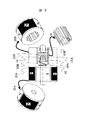
図7は本発明の他の実施形態をなす電動機を示す。
【0052】
前記第1回転子20Aはシャフト22に固定し、前記第2回転子20Bはシャフト22と可動自在に結合すると共に、シャフトの一部にはボルトのネジ部23Aと第2の界磁用磁石の内周側にスリーブ41を固定し、かつスリーブ41の内側にナット部23Bを固定したものを一体化すれば、シャフト22に対して第2回転子20Bはボルトのネジ部からナット部が外れる方向に第1回転子20Aと第2回転子20Bの間の間隔が広がりながら回転する。
【0053】
第2の界磁用磁石の内周側とシャフト22間にはわずかな遊びがあることで、回転と共に第2の界磁用磁石の内周側とシャフト22間に鎖交磁束変化が生じると、電食等の障害があるが、前記スリーブ11は鉄より電気抵抗率が高い非磁性体を用いることで、第2の界磁用磁石の内周側とシャフト22間には磁気的にも、電気的にも絶縁を行う効果がある。
【0054】
前記第2の界磁用磁石と前記シャフト間には回転運動と往復運動及び複合運動を案内出来るようにスリーブ41の内側に支持機構40A,40Bを備えた。
【0055】
第2回転子20Bはシャフトの一部にボルトのネジ部23Aを設け、これとお互いにネジの機能を持たせて、第2の界磁用磁石の側面から離れたところには移動可能なストッパー24を設ける。ストッパー24とシャフト間、ストッパーと第2回転子20Bの側面間には回転運動と往復運動及び複合運動を案内出来るように支持機構42,47を設ける。支持機構42はスラスト軸受の機能を持ち、支持機構47はラジアル軸受でありながら回転運動と往復運動及び複合運動を案内する機能を持つ。
【0056】
さらに、ばね48を設けることで、支持機構42はスラスト軸受としてその機能が向上する効果がある。
【0057】
ストッパー24はシャフトと平行に移動可能なサーボ機構の一例として電磁クラッチについて述べる。
【0058】
電磁クラッチの構成は、ヨーク44にコイル46が巻かれて、ストッパー24は可動鉄心の機能を兼用することで良い。ヨーク44とコイル46は電動機のフレーム49、若しくは車体の一部に(図に示せず)固定し、ヨーク44とストッパー24の間にばね45を備えて励磁遮断時の復帰装置の機能を持つ。電動機のフレーム49とシャフト22の間には軸受50で支える。
【0059】
図7はコイル46に無励磁状態の概略であり、図8はコイル46に励磁状態の概略を示す。
【0060】
コイル46を励磁することでヨーク44は強力な電磁石となり、可動鉄心の機能を兼用するストッパー24を吸引する。
【0061】
ここに示した電磁クラッチはストッパー24をシャフトと平行に可変可能なサーボ機構の一例であり、油圧アクチュエータ,回転機とボールネジなどによる直線駆動装置,リニアモータなどを用いることで、より細かなストッパーの位置決めが可能である。
【0062】
図9は第2回転子20Bの内側に固定されるスリーブ41の一例を示す。
【0063】
それらの固定方法の一つとして、第2回転子20Bとスリーブ41からなる2つの部品の接する面のお互いに凸凹を設けて固定した。また、シャフト22に固定した第1回転子20Aとシャフト22と分離した第2回転子20Bの内側違いの概略を示す。
【0064】
図10は本発明の他の実施例を示す。
【0065】
前記第1の界磁用磁石と前記第2の界磁用磁石が接する前記第1の界磁用磁石側面に凹部53を設け、前記第2の界磁用磁石には前記スリーブの機能を兼ねた突起部54を設けた構造である。突起部54はスリーブ41と一体ものでも良いし、第2回転子20Bと一体ものでも良い。よって、スリーブ41の十分なスペースが確保出来、ばね48、支持機構40A,40B、ナット部23Bらを有効に配置することで、第2回転子20Bの軸長積厚が薄い電動機に有効な手法の一つである。
【0066】
図11は本発明の他の実施例を示す。
【0067】
図11に示す基本構成要素は図7と同じであるが、電磁クラッチに相当する一部を変更した一例である。図11はコイル46が励磁状態であり、励磁遮断時はばね45によりヨーク44とストッパー24は切り離れる。また、第2回転子20Bにトルクが加わるボルトのネジ部23Aとナット部23Bの相互作用によるネジの機能により推力が得られる特性を持つ。よって、ネジとトルクの相互関係でストッパー24を押し出す推力が加われば、コイル46の励磁を遮断するとストッパー24はヨーク44と切り離れる。ヨーク44はアーム52を介してフレーム49、若しくは主軸の一部に(図に示せず)固定される。
【0068】
図11に示す電磁クラッチは、図7,図8の説明と同じくストッパー24をシャフトと平行に可変可能なサーボ機構の一例であり、油圧アクチュエータ,回転機とボールネジなどによる直線駆動装置,リニアモータなどを用いることで、より細かなストッパー24の位置決めが可能である。
【0069】
図12は本発明の他の実施例を示す。
【0070】
図12はストッパー24を固定した一例であり、ストッパー24と第2回転子20Bの間、第1回転子20Aと第2回転子20Bの間には、ばね48,ばね51を複数個設けることで、第2回転子20Bの急激な変動を押さえたり、トルク方向による動きを補助する効果がある。
【0071】
勿論、各図に示した各々の構成要素は様々な方法で組合わせることが可能であり、用途に合わせて加えたり、取り外すことは言うまでもない。
【0072】
図13は本発明の他の実施形態をなす電動機を示す。
【0073】
本発明の電動機の特徴として、第1回転子20Aはシャフト22に対してしっかり固定されているのに対して、第2回転子20Bはシャフト22に対して自由度を持つことになる。従って、第2回転子20Bとシャフト22間にはわずかな機械的な寸法の遊びがあり、大きなトルクや遠心力などが加わると偏心することもあり得る。よって、第1の界磁用磁石を有する第1回転子20Aと前記固定子間のエアギャップGap1より第2の界磁用磁石を有する第2回転子20Bと前記固定子間のエアギャップGap2の方が大きくしたことで、偏心による第2回転子20Bと前記固定子との機械的な接続を省く効果がある。
【0074】
図14は本発明の他の実施形態をなす回転電機を示す。
【0075】
前記図2に示した第2回転子のネジ部23をなくし、回転角θ分可変できる機構を設けたことを特徴とする永久磁石形同期回転電機である。
【0076】
前記図2に示した第2回転子のネジ部分の代わりに、シャフト22に歯車のように凹凸を設けて、第2回転子20Bの内径側にはシャフトが挿入できるように凸凹を設ける。ただし、シャフト22を第2回転子20Bの内径側に挿入したときには、かみ合う歯の幅より溝の幅を大きくして所定の回転角θ分可変できるようにする。さらに、かみ合う歯と溝の間にはスプリング26とダンパー27を設けることで、急な衝突を和らげる効果がある。
【0077】
図18は本発明の他の実施形態をなす電動機を示す。
【0078】
本発明の電動機の特徴として、第2回転子20Bの外周側の長さより内周側の長さを短くし、第2回転子20B内側にストッパー24とサーボ機構25を備えた構造である。よって、ストッパー24とサーボ機構25による回転子全体の軸方向長さを押さえる効果がある。
【0079】
以上の本発明の説明では、4極機を対象に述べたが、2極機、又は、6極機以上に適用出来る事は言うまでもない。一例として、図15には本発明を8極機に適用した場合の永久磁石形同期電動機の回転子概略図を示す。また、回転子においては埋め込み磁石形でも、表面磁石形でも適用出来る事は言うまでもない。
【0080】
図17は主軸電動機としては本発明の電動機を用いて、軸送り機構としてはリニアモータを用いた概略を示す。
【0081】
最近、回転機とボールネジの組合せによる軸送り装置よりも、リニアモータによるダイレクト軸送りが静かで移送速度も早い等のメリットが多くあり、リニアモータを採用した工作機械が増えている。
【0082】
勿論、ある軸はリニアモータによる軸送り、他方の軸は回転機とボールネジの組合せによる軸送りを用いる複合型軸送り装置でも良い。
【0083】
【発明の効果】
本発明の永久磁石形同期電動機は第1の界磁用磁石と第2の界磁用磁石の磁極中心を変化させるという構成により、固定子磁極と対向する永久磁石による有効磁束量を可変出来、広範囲可変速制御が要求される工作機械の電動機に適している。
【図面の簡単な説明】
【図1】本発明の一実施形態をなす電動機と工作機械とのレイアウト図を示す。
【図2】図1の電動機の全体概略を示す。
【図3】図1の電動機の回転子同磁極中心が揃った場合概略を示す。
【図4】図1の電動機の回転子同磁極中心がずれた場合概略を示す。
【図5】図1の電動機の回転角速度に対する諸特性を示す。
【図6】図1の電動機の制御ブロック図を示す。
【図7】本発明の他の実施形態をなす電動機を示す(アクチュエータOFF状態)。
【図8】本発明の他の実施形態をなす電動機を示す(アクチュエータON状態)。
【図9】本発明の他の実施形態をなす電動機の回転子の内側を示す。
【図10】本発明の他の実施形態をなす電動機の回転子の内側を示す。
【図11】本発明の他の実施形態をなす電動機を示す(アクチュエータON状態)。
【図12】本発明の他の実施形態をなす電動機を示す。
【図13】本発明の他の実施形態をなす電動機の回転子概略図を示す(Gapの差を付ける)。
【図14】本発明の他の実施形態をなす電動機の回転子の概略図を示す。
【図15】本発明の他の実施形態をなす電動機の回転子概略図を示す(8極機に適用した場合)。
【図16】本発明の他の実施形態をなす電動機の軸方向変位測定の概略図を示す。
【図17】本実施例の電動機を配置した他の工作機械の概略を示す(リニアモータ軸送り)。
【図18】本発明の他の実施形態をなす電動機の回転子概略図を示す(ストッパーを第2回転子の内側に備える)。
【符号の説明】
2…電動機、4…インバータ、10…固定子鉄心、11…電機子巻線、12…冷却水流路、13…ハウジング、20…回転子、20A…第1回転子、20B…第2回転子、21…永久磁石、21A…第1回転子永久磁石、21B…第2回転子永久磁石、22…シャフト、23…ネジ、24…ストッパー、25…ストッパー駆動用アクチュエータ、90…圧縮機、91…タービン、101…運転判断部、102…電流制御、103…回転座標変換部、104…PWMインバータ主回路、105…2軸変換部。[0001]
BACKGROUND OF THE INVENTION
The present invention relates to an electric motor using a permanent magnet as a field, and more particularly to an electric motor that drives and generates power for a machine tool and a control method thereof.
[0002]
[Prior art]
In the conventional permanent magnet motor, the induced electromotive force E is determined by the constant magnetic flux Φ generated by the permanent magnet disposed in the rotor and the rotational angular velocity ω of the motor. That is, when the rotational angular velocity ω (rotation number) of the motor increases, the induced electromotive force of the motor increases in proportion.
[0003]
Therefore, high torque can be obtained in the low speed range, but the induced electromotive force increases as the rotational speed increases, so that the variable speed range is narrow due to the limitation of the output voltage of the inverter, making it difficult to operate in the high speed range. However, widening the high-speed operating range by field-weakening control.
[0004]
In addition, the spindle motor of machine tools is equipped with a gear mechanism to ensure a predetermined output in a wide speed range so that it can cope with various machining conditions. Recently, each phase winding of the spindle motor is driven by switching to a low-speed winding and a high-speed winding using a winding switching device according to the rotational speed of the spindle.
[0005]
[Problems to be solved by the invention]
In the permanent magnet motor, it is possible to expand the high-speed operation range by field-weakening control described in the prior art by using a flux-weakening current (armature d-axis current). .
[0006]
Further, when processing difficult-to-cut materials such as aluminum alloys for aircraft, high-speed rotation is desirable, but there is a limit due to an increase in the induced electromotive force of the permanent magnet.
[0007]
If a gear mechanism is provided to ensure a predetermined output in a wide speed range, the number of mechanical parts is large and there is a problem of noise vibration.
[0008]
When a winding switching device is used for each phase winding according to the rotation speed of the main shaft, the number of lead wires from the motor body is large, and the winding switching control device and its structure are complicated. is there.
[0009]
An object of this invention is to provide the machine tool provided with the electric motor which can ensure a predetermined output in a wide speed range.
[0010]
[Means for Solving the Problems]
The present invention is a machine tool for performing desired processing on a workpiece by relatively moving the tool and the workpiece, and is provided with a spindle on which a tool is mounted and a head of the spindle, and the spindle is driven to rotate. Electric motor, an inverter for controlling the driving of the electric motor, a controller for controlling the inverter, and a tool data setting means for presetting the magnitude of the output of the electric motor suitable for the use condition for each tool to be used The electric motor includes a stator having a primary winding and a stator magnetic pole, a field magnet and a shaft facing the stator magnetic pole, and the field magnets have different polarities sequentially in the rotation direction. A first field magnet in which magnetic poles are arranged, and a second field magnet in which relative rotation is possible with respect to the first field magnet, and different magnetic poles are sequentially arranged behind the rotation. Including magnet A rotator, depending on the balance between the torque generated in the magnetic acting force and the rotor between the first field magnet and the second field magnet, the first field magnet And a displacement mechanism for displacing the second field magnet in the axial direction and the rotational direction, the displacement mechanism depending on the rotational speed of the rotor depending on the driving speed of the electric motor or the load state. same field magnet and the first field magnet and the second field magnets by balancing a rotating torque generated in the magnetic acting force and the rotor between the second field magnet a displacement function to line up the magnetic pole center of each magnetic pole of polarity, each of the same polarity of the first field magnet and the second field magnet by the direction of the rotational torque generated in the rotor to become opposite characterized in that it comprises a displacement function of shifting the poles of the magnetic pole in the heart.
[0011]
DETAILED DESCRIPTION OF THE INVENTION
Embodiments of the present invention will be described below.
[0012]
FIG. 1 shows an outline of a machine tool in which a permanent magnet type synchronous motor according to this embodiment is arranged.
[0013]
A
[0014]
With such a configuration, the spindle motor, each axis feed motor, and the like are operated according to the tool data and machining commands set from the
[0015]
FIG. 2 shows an outline when the magnetic pole center of the rotor of the motor shown in FIG. 1 is shifted.
[0016]
An armature winding 11 is wound around the
[0017]
The permanent magnet embedded
[0018]
In the
[0019]
The inner diameter side of the
[0020]
Further, a
[0021]
The principle of changing the effective magnetic flux of the permanent magnet in accordance with the torque direction by using the above structure will be described.
[0022]
Basically, in an electric motor that uses an armature winding for the stator and a permanent magnet for the rotor, the rotation direction of the rotor is the same when acting as a motor and when acting as a generator (regenerative braking). The direction of torque received by the rotor when working as an electric motor is opposite to that when working as a generator.
[0023]
Also, when working with the same electric motor, if the opposite rotational direction of the rotor, also the opposite torque direction. Similarly, when working with the same generator, if the rotational direction of the rotor in the opposite, also in the opposite torque direction.
[0024]
The basic theory based on the rotation direction and the torque direction described above is applied to the electric motor of the machine tool according to the embodiment of the present invention as follows.
[0025]
When operating in a low-speed rotation region where a large torque is required, as shown in FIG. 3, the same magnetic pole centers of the
[0026]
Next, when operating in high-speed rotation areas such as difficult-to-cut materials such as aircraft aluminum alloys,
As shown in FIG. 4, the
[0027]
FIG. 4 shows an outline of a state where the center of the magnetic pole is shifted while the interval between the
[0028]
3 and FIG. 4 are diagrams related to the
[0029]
Also, when rotating as an electric motor, the direction of torque is opposite during forward rotation and reverse rotation, and the state shown in FIG. 3 during forward rotation is the state shown in FIG.
[0030]
Of course, the inner diameter side of the
[0031]
For example, when operating in a low-speed rotation region where a large torque is required for forward rotation, as shown in FIG. 3, the screws are arranged so that the centers of the same magnetic poles of the
[0032]
Next, if the rotation is reversed, when operating in a high-speed rotation region such as machining difficult-to-cut materials such as aircraft aluminum alloys, the
[0033]
The effect | action of the induced electromotive force by the electric motor of this invention is demonstrated.
[0034]
FIG. 5 shows the characteristics of the effective magnetic flux, the induced electromotive force, and the terminal voltage with respect to the rotational angular velocity of the permanent magnet type synchronous motor.
[0035]
The induced electromotive force E of the permanent magnet type synchronous motor is determined by the constant magnetic flux Φ generated by the permanent magnet arranged in the rotor and the rotational angular velocity ω of the motor. That is, as shown in FIG. 5A, if the magnetic flux Φ1 generated by the permanent magnet is constant, the induced electromotive force E1 of the motor increases in proportion to the increase in the rotational angular velocity ω (the number of rotations).
[0036]
However, the output voltage of the inverter is limited due to the terminal voltage of the power source and the capacity of the inverter, and the induced electromotive force generated by the motor is also limited. For this reason, in the permanent magnet type synchronous motor, so-called weak magnetic flux control must be performed so that the d-axis armature current flows in order to reduce the magnetic flux generated by the permanent magnet in a region of a certain rotational speed or more.
[0037]
Since the induced electromotive force rises in proportion to the rotational angular velocity, it is necessary to increase the d-axis armature current of the flux-weakening control. Therefore, it is necessary to flow a large current through the coil that is the primary conductor. Heat increases. For this reason, there is a possibility that the efficiency of the motor as a motor in a high rotation region is reduced, the permanent magnet is demagnetized due to heat generation exceeding the cooling capacity, and the like.
[0038]
For example, as shown in FIG. 5 (a), when the magnetic flux Φ1 generated by the permanent magnet arranged in the rotor is changed to the magnetic flux Φ2 at a certain rotational angular velocity ω1 (rotation speed), the induced electromotive force E1 of the motor It is possible to limit the maximum value of the induced electromotive force by changing to the induced electromotive force E2 characteristic.
[0039]
Similarly, FIG. 5B schematically shows that the induced electromotive force E can be kept constant if the magnetic flux Φ changes more finely according to the rotational angular velocity ω (the number of rotations).
[0040]
Furthermore, as one example of means for obtaining the characteristics shown in FIG. 5B, the first field magnet is fixed to a shaft, and the second field magnet is movable with respect to the shaft. In addition to being coupled, the shaft is provided with a screw portion of the bolt and a nut portion on the inner peripheral side of the second field magnet so as to have a screw function with each other and away from the side surface of the second field magnet. This can be achieved by using an actuator provided with a stopper and having a servo mechanism that can move the stopper in parallel with the shaft in accordance with the rotational speed.
[0041]
FIG. 6 shows a configuration diagram of a control circuit of the spindle motor.
[0042]
FIG. 6 shows a control block diagram of the
[0043]
First, information set from the operation pendant (76 in FIG. 1), information (tool number, position information, etc.) from the sensors provided on the spindle and each axis feeding device, and the permanent magnet type
[0044]
The output from the
[0045]
In the embodiment shown in FIG. 6, the
[0046]
Further, the permanent magnet type synchronous motor of the present invention aligns or shifts the magnetic pole centers of the first rotor and the second rotor according to the operating condition, so the first field magnet And the second field magnet have a function of correcting the advance angle of the current supply by the controller that controls the inverter according to the deviation of the composite magnetic pole position.
[0047]
An embodiment for correcting the advance angle of the current supply will be described.
[0048]
The first field magnet is fixed to a shaft, the second field magnet is movably coupled to the shaft, and a screw portion of a bolt and an inner periphery of the second field magnet are connected to the shaft. When the nut portion is provided on the side and the functions of the screws are given to each other, the second field magnet moves in the axial direction while rotating.
[0049]
FIG. 13 shows the relationship between the rotation angle and the amount of axial displacement when the magnetic pole centers of the first and second rotors match or deviate depending on the operating conditions.
[0050]
In FIG. 16, the rotation angle θ of the second rotor and the axial displacement amount ΔL are in a proportional relationship, and the axial displacement amount ΔL is measured using the displacement measuring device 64 and fed back to the controller of the inverter and fed back to the first field. The value converted into the deviation angle of the composite magnetic pole position between the magnet for magnet and the second field magnet is used for optimum control for correcting the advance angle of current supply.
[0051]
FIG. 7 shows an electric motor according to another embodiment of the present invention.
[0052]
The
[0053]
When there is a slight play between the inner peripheral side of the second field magnet and the
[0054]
Between the second field magnet and the shaft,
[0055]
The
[0056]
Further, the provision of the
[0057]
An electromagnetic clutch will be described as an example of a servo mechanism in which the
[0058]
The electromagnetic clutch may be configured such that the
[0059]
7 shows an outline of the
[0060]
By exciting the
[0061]
The electromagnetic clutch shown here is an example of a servo mechanism in which the
[0062]
FIG. 9 shows an example of a
[0063]
As one of those fixing methods, the surfaces where the two parts including the
[0064]
FIG. 10 shows another embodiment of the present invention.
[0065]
A
[0066]
FIG. 11 shows another embodiment of the present invention.
[0067]
The basic components shown in FIG. 11 are the same as those shown in FIG. 7, but an example in which a part corresponding to the electromagnetic clutch is changed. In FIG. 11, the
[0068]
The electromagnetic clutch shown in FIG. 11 is an example of a servo mechanism in which the
[0069]
FIG. 12 shows another embodiment of the present invention.
[0070]
FIG. 12 shows an example in which the
[0071]
Of course, each component shown in each figure can be combined in various ways, and it goes without saying that it is added or removed according to the application.
[0072]
FIG. 13 shows an electric motor according to another embodiment of the present invention.
[0073]
As a feature of the electric motor of the present invention, the
[0074]
FIG. 14 shows a rotating electrical machine according to another embodiment of the present invention.
[0075]
2 is a permanent magnet type synchronous rotating electric machine characterized in that the screw portion 23 of the second rotor shown in FIG. 2 is eliminated and a mechanism capable of varying the rotation angle θ is provided.
[0076]
Instead of the screw portion of the second rotor shown in FIG. 2, the
[0077]
FIG. 18 shows an electric motor according to another embodiment of the present invention.
[0078]
As a feature of the electric motor of the present invention, the length on the inner peripheral side is shorter than the length on the outer peripheral side of the
[0079]
In the above description of the present invention, a 4-pole machine has been described, but it goes without saying that it can be applied to a 2-pole machine or a 6-pole machine or more. As an example, FIG. 15 shows a schematic view of a rotor of a permanent magnet type synchronous motor when the present invention is applied to an octupole machine. Further, it goes without saying that the rotor can be applied to either an embedded magnet type or a surface magnet type.
[0080]
FIG. 17 shows an outline in which the motor of the present invention is used as the spindle motor and a linear motor is used as the shaft feed mechanism.
[0081]
Recently, there are many merits such as a direct shaft feed by a linear motor and a faster transfer speed than a shaft feed device using a combination of a rotating machine and a ball screw, and the number of machine tools adopting a linear motor is increasing.
[0082]
Of course, one shaft may be a shaft feed by a linear motor, and the other shaft may be a composite shaft feed device using a shaft feed by a combination of a rotating machine and a ball screw.
[0083]
【The invention's effect】
The permanent magnet type synchronous motor of the present invention can vary the effective magnetic flux amount by the permanent magnet facing the stator magnetic pole by changing the magnetic pole centers of the first field magnet and the second field magnet. Suitable for machine tool motors that require a wide range of variable speed control.
[Brief description of the drawings]
FIG. 1 shows a layout diagram of an electric motor and a machine tool according to an embodiment of the present invention.
FIG. 2 shows an overall outline of the electric motor of FIG.
FIG. 3 shows an outline when the rotor magnetic pole centers of the motor of FIG. 1 are aligned.
4 shows an outline when the rotor magnetic pole center of the electric motor of FIG. 1 is shifted. FIG.
5 shows various characteristics with respect to the rotational angular velocity of the electric motor shown in FIG.
6 shows a control block diagram of the electric motor of FIG. 1. FIG.
FIG. 7 shows an electric motor according to another embodiment of the present invention (actuator OFF state).
FIG. 8 shows an electric motor according to another embodiment of the present invention (actuator ON state).
FIG. 9 shows an inner side of a rotor of an electric motor according to another embodiment of the present invention.
FIG. 10 shows an inner side of a rotor of an electric motor according to another embodiment of the present invention.
FIG. 11 shows an electric motor according to another embodiment of the present invention (actuator ON state).
FIG. 12 shows an electric motor according to another embodiment of the present invention.
FIG. 13 is a schematic view of a rotor of an electric motor according to another embodiment of the present invention (Gap difference is given).
FIG. 14 is a schematic view of a rotor of an electric motor according to another embodiment of the present invention.
FIG. 15 is a schematic view of a rotor of an electric motor according to another embodiment of the present invention (when applied to an 8-pole machine).
FIG. 16 is a schematic view showing an axial displacement measurement of an electric motor according to another embodiment of the present invention.
FIG. 17 shows an outline of another machine tool in which the electric motor of this embodiment is arranged (linear motor shaft feed).
FIG. 18 is a schematic view of a rotor of an electric motor according to another embodiment of the present invention (a stopper is provided inside the second rotor).
[Explanation of symbols]
DESCRIPTION OF
Claims (14)
前記工具が装着される主軸と、
該主軸の頭に設けられると共に、前記主軸を回転駆動する電動機と、
該電動機の駆動を制御するインバータと、
該インバータを制御するコントローラと、
使用する前記工具ごとにその使用条件に合った前記電動機の出力の大きさを予め設定するための工具データ設定手段とを備え、
前記電動機は、
一次巻線及び固定子磁極を有する固定子と、
前記固定子磁極に対向する界磁用磁石及びシャフトを有するものであって、前記界磁用磁石が、回転方向に順次異なった極性の磁極が並んでいる第1の界磁用磁石と、この第1の界磁用磁石に対して相対回転が可能で、回転後方に順次異なった磁性の磁極が並んでいる第2の界磁用磁石とを含み構成された回転子と、
前記第1の界磁用磁石と前記第2の界磁用磁石との間の磁気作用力と前記回転子に発生するトルクとの釣合いに応じて、前記第1の界磁用磁石に対して前記第2の界磁用磁石を軸方向及び回転方向に変位させる変位機構とを有し、
前記変位機構は、
前記電動機の駆動速度又は負荷状態による前記回転子の回転方向に応じて、前記第1の界磁用磁石と前記第2の界磁用磁石との間の磁気作用力と前記回転子に発生する回転トルクとの釣合いにより前記第1の界磁用磁石と前記第2の界磁用磁石の同じ極性の各磁極の磁極中心を並ばせる変位機能と、前記回転子の発生する回転トルクの方向が反対になることにより前記第1の界磁用磁石と前記第2の界磁用磁石の同じ極性の各磁極の磁極中心をずらす変位機能とを備えている
ことを特徴とする工作機械。In a machine tool that performs a desired process on the workpiece by relatively moving the tool and the workpiece,
A spindle on which the tool is mounted;
An electric motor that is provided at the head of the main shaft and that rotationally drives the main shaft;
An inverter for controlling the drive of the electric motor;
A controller for controlling the inverter;
Tool data setting means for presetting the magnitude of the output of the electric motor that matches the use conditions for each tool to be used;
The motor is
A stator having a primary winding and a stator pole;
A field magnet and a shaft facing the stator magnetic pole, wherein the field magnet includes a first field magnet in which magnetic poles of different polarities are sequentially arranged in a rotation direction; A rotor configured to include a second field magnet that is capable of relative rotation with respect to the first field magnet and in which different magnetic poles are sequentially arranged behind the rotation;
Depending on the balance between the torque generated in the magnetic action force between said rotor between said first of said the field magnet second field magnet relative to said first field magnet A displacement mechanism for displacing the second field magnet in the axial direction and the rotational direction,
The displacement mechanism is
The magnetic force generated between the first field magnet and the second field magnet is generated in the rotor according to the rotation speed of the rotor depending on the driving speed or load state of the electric motor. a displacement function to line up the magnetic pole center of the same magnetic poles of the polarity of the first of the the field magnet second field magnets by balancing the rotating torque, the rotating torque generated by the said rotor tool characterized in that it has a displacement function of shifting the first field magnet and the second magnetic-field cardiac in magnetic poles of the same magnetic poles of polarity of the magnets by the direction is reversed machine.
前記回転子は、
前記電動機を低速で駆動して前記主軸を回転駆動させる場合、正回転で回転し、
前記電動機を高速低トルク又は軽負荷で駆動して前記主軸を回転駆動させる場合、逆回転で回転し、
前記変位機構は、
前記回転子が正回転の場合、前記第1の界磁用磁石と前記第2の界磁用磁石との間の磁気作用力と前記回転子に発生する回転トルクとの釣合いにより前記第1の界磁用磁石と前記第2の界磁用磁石の同じ極性の各磁極の磁極中心を並ばせ、
前記回転子が逆回転の場合、前記回転子の発生する回転トルクの方向が反対になることにより前記第1の界磁用磁石と前記第2の界磁用磁石の同じ極性の各磁極の磁極中心をずらす
ことを特徴とする工作機械。The machine tool according to claim 1,
The rotor is
When the electric motor is driven at a low speed and the main shaft is driven to rotate, the motor rotates at a normal rotation,
When driving the motor with high speed, low torque or light load to rotate the spindle, it rotates in reverse rotation,
The displacement mechanism is
If the rotor is positive rotation, the first by the balance of the rotating torque generated in the magnetic action force between said rotor between said first of said the field magnet second field magnets They were lined up the same magnetic pole center of each magnetic pole of polarity of the the field magnet second field magnets of
If the rotor is reversely rotated, the same magnetic poles of the polarity of said second field magnet and the first field magnet by the direction of the rotational torque is reversed for generating the rotor machine tool, characterized in that shifting the heart during pole.
前記第1の界磁用磁石は前記シャフトに対して固定されており、
前記第2の界磁用磁石は前記シャフトに対して可動自在に設けられており、
前記第2の界磁用磁石と前記シャフトは、前記シャフトにもたせたボルト機能と、前記第2の界磁用磁石にもたせたナット機能との関係からなるねじ機能によってお互いに接続されている
ことを特徴とする工作機械。The machine tool according to claim 1,
The first field magnet is fixed to the shaft;
The second field magnet is movably provided with respect to the shaft;
The second field magnet and the shaft are connected to each other by a screw function comprising a relationship between a bolt function applied to the shaft and a nut function applied to the second field magnet. A machine tool characterized by
前記第2の界磁用磁石の側面には、前記第2の界磁用磁石の所定以上の変位を防止するためのストッパーが設けられており、
前記ストッパーは前記シャフトに対して平行に可変する
ことを特徴とする工作機械。The machine tool according to claim 3,
A stopper is provided on a side surface of the second field magnet to prevent displacement of the second field magnet beyond a predetermined level.
The machine tool according to claim 1, wherein the stopper is variable in parallel to the shaft.
前記ストッパーは、回転速度に応じて前記シャフトと平行にサーボ機構によって可変させられる
ことを特徴とする工作機械。The machine tool according to claim 4,
The machine tool according to claim 1, wherein the stopper is variable by a servo mechanism in parallel with the shaft according to a rotational speed.
前記コントローラは、前記第1の界磁用磁石と前記第2の界磁用磁石とのずれに基づいた合成磁極位置のずれに応じて電流供給の進角を制御する
ことを特徴とする工作機械。The machine tool according to claim 1,
The controller controls an advance angle of current supply according to a deviation of a composite magnetic pole position based on a deviation between the first field magnet and the second field magnet. .
前記第2の界磁用磁石と前記シャフトとの間には、回転運動と往復運動の複合運動を案内するための支持機構が複数設けられている
ことを特徴とする工作機械。The machine tool according to claim 3,
Wherein between the second field magnet and the shaft, machine tool, characterized in that the support mechanism for guiding the composite movement of the rotary motion and reciprocating motion is provided with a plurality.
前記第2の界磁用磁石と前記シャフトとの間には、それらの間を電気的及び磁気的に絶縁するためのスリーブが設けられており、
前記スリーブは前記第2の界磁用磁石の内周側に固定されている
ことを特徴とする工作機械。The machine tool according to claim 3,
Between the second field magnet and the shaft, a sleeve for electrically and magnetically insulating between them is provided,
The machine tool according to claim 1, wherein the sleeve is fixed to an inner peripheral side of the second field magnet.
前記スリーブは、鉄よりも電気抵抗率が高い非磁性体である
ことを特徴とする工作機械。The machine tool according to claim 8 ,
The machine tool according to claim 1, wherein the sleeve is a non-magnetic material having a higher electrical resistivity than iron.
前記第2の界磁用磁石の前後には、前記第2の界磁用磁石の回転運動と往復運動の複合運動を案内するばねが設けられている
ことを特徴とする工作機械。The machine tool according to claim 3,
The machine tool before and after the second field magnet, wherein the spring to guide the composite movement of the rotary motion and reciprocating motion of said second field magnet is provided.
前記第1の界磁用磁石の側面で前記第2の界磁用磁石と接する側面には凹部が設けられており、
前記第2の界磁用磁石の側面で前記第1の界磁用磁石と接する側の側面には突起部が設けられており、
前記突起部は、前記第2の界磁用磁石と前記シャフトとの間を電気的及び磁気的に絶縁するためのスリーブを兼ねている
ことを特徴とする工作機械。The machine tool according to claim 3,
A concave portion is provided on a side surface of the first field magnet that is in contact with the second field magnet.
A protrusion is provided on a side surface of the second field magnet that is in contact with the first field magnet.
The machine tool according to claim 1, wherein the protrusion serves as a sleeve for electrically and magnetically insulating between the second field magnet and the shaft.
前記ストッパーは、前記第2の界磁用磁石と前記シャフトに対して回転運動と往復運動の複合運動を案内する支持機構を備えている
ことを特徴とする工作機械。The machine tool according to claim 4,
The stopper is provided with a support mechanism for guiding a combined motion of a rotational motion and a reciprocating motion with respect to the second field magnet and the shaft.
前記第2の界磁用磁石を有する回転子と前記固定子との間のエアギャップは、前記第1の界磁用磁石を有する回転子と前記固定子との間のエアギャップよりも大きい
ことを特徴とする工作機械。The machine tool according to claim 3,
The air gap between the rotor having the second field magnet and the stator is larger than the air gap between the rotor having the first field magnet and the stator. A machine tool characterized by
前記ストッパーと前記サーボ機構は前記第2の界磁用磁石の内周側に設けられている
ことを特徴とする工作機械。The machine tool according to claim 5,
The machine tool according to claim 1, wherein the stopper and the servo mechanism are provided on an inner peripheral side of the second field magnet.
Priority Applications (4)
| Application Number | Priority Date | Filing Date | Title |
|---|---|---|---|
| JP2001053428A JP3861610B2 (en) | 2001-02-28 | 2001-02-28 | Machine Tools |
| EP02003284A EP1237257A3 (en) | 2001-02-28 | 2002-02-22 | Machine tool |
| US10/083,531 US6841911B2 (en) | 2001-02-28 | 2002-02-27 | Machine tool |
| CN02106447.4A CN1231328C (en) | 2001-02-28 | 2002-02-28 | Machine tool |
Applications Claiming Priority (1)
| Application Number | Priority Date | Filing Date | Title |
|---|---|---|---|
| JP2001053428A JP3861610B2 (en) | 2001-02-28 | 2001-02-28 | Machine Tools |
Publications (3)
| Publication Number | Publication Date |
|---|---|
| JP2002254268A JP2002254268A (en) | 2002-09-10 |
| JP2002254268A5 JP2002254268A5 (en) | 2005-10-06 |
| JP3861610B2 true JP3861610B2 (en) | 2006-12-20 |
Family
ID=18913894
Family Applications (1)
| Application Number | Title | Priority Date | Filing Date |
|---|---|---|---|
| JP2001053428A Expired - Fee Related JP3861610B2 (en) | 2001-02-28 | 2001-02-28 | Machine Tools |
Country Status (4)
| Country | Link |
|---|---|
| US (1) | US6841911B2 (en) |
| EP (1) | EP1237257A3 (en) |
| JP (1) | JP3861610B2 (en) |
| CN (1) | CN1231328C (en) |
Families Citing this family (33)
| Publication number | Priority date | Publication date | Assignee | Title |
|---|---|---|---|---|
| JP3879413B2 (en) * | 2001-02-28 | 2007-02-14 | 株式会社日立製作所 | Conveying system and rotating electric machine |
| JP3861610B2 (en) * | 2001-02-28 | 2006-12-20 | 株式会社日立製作所 | Machine Tools |
| US6664694B2 (en) * | 2001-09-27 | 2003-12-16 | Tai-Her Yang | Rotor axial activation modulation of electric machinery due to centrifugal force |
| JP3937966B2 (en) * | 2002-07-31 | 2007-06-27 | 株式会社日立製作所 | Rotating electric machine and automobile equipped with it |
| KR100677114B1 (en) * | 2004-04-27 | 2007-02-02 | 삼성전자주식회사 | Method and apparatus for recording/reproducing data from/on information storage medium |
| JP2006136126A (en) * | 2004-11-05 | 2006-05-25 | Toyota Industries Corp | Electric motor and electric compressor |
| DE102005046531A1 (en) * | 2005-09-28 | 2007-03-29 | Volkswagen Ag | Stepless transmission for motor vehicle, has variator formed as electromagnetic transmission with drive and output rotors that are rotatable supported and temporarily connected with input and output shafts, respectively, and stator |
| US7821217B2 (en) * | 2006-05-22 | 2010-10-26 | Black & Decker Inc. | Electronically commutated motor and control system employing phase angle control of phase current |
| DE102006026186A1 (en) * | 2006-05-30 | 2007-12-06 | Index-Werke Gmbh & Co. Kg Hahn & Tessky | machine tool |
| US20080265702A1 (en) * | 2007-04-26 | 2008-10-30 | Don-Lon Yeh | Permanent magnetic brushless motor with length adjustable air gap based on load |
| DE502007003473D1 (en) * | 2007-06-30 | 2010-05-27 | Trumpf Werkzeugmaschinen Gmbh | Machine tool with a functional unit with linear drive |
| JP2009126404A (en) * | 2007-11-26 | 2009-06-11 | Hitachi Ltd | Hybrid vehicle |
| JP2010161832A (en) * | 2009-01-06 | 2010-07-22 | Hitachi Ltd | Permanent magnet rotating electrical machine |
| JP2011193711A (en) * | 2010-02-16 | 2011-09-29 | Seiko Epson Corp | Motor, electronic apparatus, motor-driven compressor, moving body, power generator, and robot |
| US20150042186A1 (en) * | 2010-12-10 | 2015-02-12 | Mario A. Galvan | Electrical system and method for sustaining an external load |
| CN102255452A (en) * | 2011-07-08 | 2011-11-23 | 广东工业大学 | Hybrid excitation motor device |
| JP5722183B2 (en) * | 2011-09-29 | 2015-05-20 | 本田技研工業株式会社 | Electric motor |
| US10263480B2 (en) | 2012-03-20 | 2019-04-16 | Linear Labs, LLC | Brushless electric motor/generator |
| US9729016B1 (en) | 2012-03-20 | 2017-08-08 | Linear Labs, Inc. | Multi-tunnel electric motor/generator |
| KR102048601B1 (en) | 2012-03-20 | 2019-11-25 | 리니어 랩스, 엘엘씨 | An improved dc electric motor/generator with enhanced permanent magnet flux densities |
| US10284029B2 (en) | 2012-03-20 | 2019-05-07 | Linear Labs, LLC | Brushed electric motor/generator |
| JP5842852B2 (en) * | 2013-04-02 | 2016-01-13 | トヨタ自動車株式会社 | Rotating electrical machine control system and rotating electrical machine control method |
| US10447103B2 (en) | 2015-06-28 | 2019-10-15 | Linear Labs, LLC | Multi-tunnel electric motor/generator |
| CN106533281A (en) * | 2015-09-11 | 2017-03-22 | 德昌电机(深圳)有限公司 | Electric tool and motor driving circuit thereof |
| JP6893306B2 (en) | 2015-10-20 | 2021-06-23 | リニア ラブズ リミテッド ライアビリティ カンパニー | Circumferential magnetic flux electromechanical machine equipped with a magnetic field weakening mechanism and how to use it |
| CN105226899A (en) * | 2015-11-13 | 2016-01-06 | 乐山三缘电机有限公司 | A kind of threephase asynchronous supported |
| CN105262299A (en) * | 2015-11-13 | 2016-01-20 | 乐山三缘电机有限公司 | Frequency conversion three-phase asynchronous motor |
| FR3057120B1 (en) * | 2016-10-03 | 2023-03-17 | Safran Helicopter Engines | ELECTRIC MACHINE FOR AIRCRAFT TURBOPROPELLER |
| CN106505813B (en) * | 2016-12-23 | 2018-06-29 | 江苏金彭车业有限公司 | A kind of automobile-used automatic tune square variable speed electric motors, particularly of electric three-wheel |
| CN109116232B (en) * | 2018-07-13 | 2019-08-02 | 上海交通大学 | Magnetic property measuring device towards seriation claw-pole type generator rotor |
| US11277062B2 (en) | 2019-08-19 | 2022-03-15 | Linear Labs, Inc. | System and method for an electric motor/generator with a multi-layer stator/rotor assembly |
| CN110868033B (en) * | 2019-11-23 | 2021-08-17 | 梅菁 | Permanent magnet motor for inhibiting short circuit fault |
| JP2023143547A (en) * | 2022-03-26 | 2023-10-06 | Msiシステム株式会社 | Tap processing device and tap processing unit |
Family Cites Families (21)
| Publication number | Priority date | Publication date | Assignee | Title |
|---|---|---|---|---|
| DE2231590A1 (en) * | 1972-06-28 | 1974-01-10 | Bosch Gmbh Robert | PERMANENT MAGNET GENERATOR |
| JPS6485644A (en) * | 1987-09-28 | 1989-03-30 | Asahi Optical Co Ltd | Preparation of ceramics composite |
| US5200660A (en) * | 1988-05-16 | 1993-04-06 | Heidelberg Goetz | Electric machine |
| US5177391A (en) * | 1990-03-14 | 1993-01-05 | Nippondenso Co., Ltd. | Power generating apparatus |
| US5387061A (en) * | 1990-12-14 | 1995-02-07 | The United States Of America As Represented By The United States Department Of Energy | Parameter monitoring compensation system and method |
| JP3496951B2 (en) * | 1992-08-04 | 2004-02-16 | 日本サーボ株式会社 | Stepper motor or permanent magnet rotor of synchronous motor |
| JPH07112366A (en) * | 1993-10-15 | 1995-05-02 | Koyo Seiko Co Ltd | Machine tool |
| US5821710A (en) * | 1996-09-30 | 1998-10-13 | Hitachi Metals, Ltd. | Brushless motor having permanent magnets |
| US6508614B1 (en) * | 1999-03-17 | 2003-01-21 | Ntn Corporation | Spindle device and machine tool utilizing the same |
| JP3468726B2 (en) * | 1999-09-01 | 2003-11-17 | 株式会社日立製作所 | Hybrid vehicles and rotating electric machines |
| WO2001051239A1 (en) * | 2000-01-12 | 2001-07-19 | Mitsubishi Denki Kabushiki Kaisha | Thrust converter, and method and device for controlling the thrust converter |
| JP2002062488A (en) * | 2000-08-11 | 2002-02-28 | Nippon Telegr & Teleph Corp <Ntt> | Light frequency sweeping apparatus |
| ITBO20000529A1 (en) * | 2000-09-13 | 2002-03-13 | Jobs Spa | MACHINE TOOL |
| JP3879414B2 (en) * | 2001-02-28 | 2007-02-14 | 株式会社日立製作所 | Air conditioner |
| JP3879412B2 (en) * | 2001-02-28 | 2007-02-14 | 株式会社日立製作所 | Power generation system |
| JP3873634B2 (en) * | 2001-02-28 | 2007-01-24 | 株式会社日立製作所 | Wind power generation system |
| JP3879415B2 (en) * | 2001-02-28 | 2007-02-14 | 株式会社日立製作所 | Washing machine |
| JP3861610B2 (en) * | 2001-02-28 | 2006-12-20 | 株式会社日立製作所 | Machine Tools |
| JP3879413B2 (en) * | 2001-02-28 | 2007-02-14 | 株式会社日立製作所 | Conveying system and rotating electric machine |
| JP4013487B2 (en) * | 2001-02-28 | 2007-11-28 | 株式会社日立製作所 | Rotating electric machine and vehicle equipped with the same |
| JP3752487B2 (en) * | 2002-12-16 | 2006-03-08 | 株式会社日立製作所 | Hybrid vehicle and rotating electric machine |
-
2001
- 2001-02-28 JP JP2001053428A patent/JP3861610B2/en not_active Expired - Fee Related
-
2002
- 2002-02-22 EP EP02003284A patent/EP1237257A3/en not_active Withdrawn
- 2002-02-27 US US10/083,531 patent/US6841911B2/en not_active Expired - Fee Related
- 2002-02-28 CN CN02106447.4A patent/CN1231328C/en not_active Expired - Fee Related
Also Published As
| Publication number | Publication date |
|---|---|
| EP1237257A2 (en) | 2002-09-04 |
| US6841911B2 (en) | 2005-01-11 |
| EP1237257A3 (en) | 2004-07-07 |
| JP2002254268A (en) | 2002-09-10 |
| CN1231328C (en) | 2005-12-14 |
| CN1382560A (en) | 2002-12-04 |
| US20020117922A1 (en) | 2002-08-29 |
Similar Documents
| Publication | Publication Date | Title |
|---|---|---|
| JP3861610B2 (en) | Machine Tools | |
| JP3873634B2 (en) | Wind power generation system | |
| JP3879413B2 (en) | Conveying system and rotating electric machine | |
| JP3879412B2 (en) | Power generation system | |
| JP3879415B2 (en) | Washing machine | |
| JP2002254268A5 (en) | ||
| JP2002262534A (en) | Rotating electric machine and vehicle for loading the same | |
| JP5392323B2 (en) | Rotating electric machine | |
| US6519959B2 (en) | Air conditioner | |
| JP2000152579A (en) | Subsynchronous reluctance electric machine | |
| JP4635829B2 (en) | Permanent magnet motor | |
| JP4525026B2 (en) | Rotating electric machine | |
| CN107579639B (en) | High-temperature-resistant permanent magnet servo motor | |
| JP4525025B2 (en) | Rotating electric machine | |
| JP2001314053A (en) | Permanent magnet field pole rotating electric machine | |
| JP2667815B2 (en) | Brushless electric motor | |
| JPH04251534A (en) | Rotating machine | |
| Hatta et al. | Preliminary Analysis for Two-Degree-of-Freedom Magnetic Geared Screw Motor with High Torque Density | |
| JP2023066881A (en) | Rotary electric machine | |
| JP2023117837A (en) | Rotary electric machine | |
| WO2001082455A1 (en) | Multipolar brushless motor |
Legal Events
| Date | Code | Title | Description |
|---|---|---|---|
| A521 | Request for written amendment filed |
Free format text: JAPANESE INTERMEDIATE CODE: A523 Effective date: 20050520 |
|
| A621 | Written request for application examination |
Free format text: JAPANESE INTERMEDIATE CODE: A621 Effective date: 20050520 |
|
| A131 | Notification of reasons for refusal |
Free format text: JAPANESE INTERMEDIATE CODE: A131 Effective date: 20060322 |
|
| RD01 | Notification of change of attorney |
Free format text: JAPANESE INTERMEDIATE CODE: A7421 Effective date: 20060418 |
|
| A521 | Request for written amendment filed |
Free format text: JAPANESE INTERMEDIATE CODE: A523 Effective date: 20060517 |
|
| TRDD | Decision of grant or rejection written | ||
| A01 | Written decision to grant a patent or to grant a registration (utility model) |
Free format text: JAPANESE INTERMEDIATE CODE: A01 Effective date: 20060905 |
|
| A61 | First payment of annual fees (during grant procedure) |
Free format text: JAPANESE INTERMEDIATE CODE: A61 Effective date: 20060918 |
|
| LAPS | Cancellation because of no payment of annual fees |