JP5550283B2 - Wind turbine generator, wind turbine generator control method, wind turbine generator system, and wind turbine generator system control method - Google Patents
Wind turbine generator, wind turbine generator control method, wind turbine generator system, and wind turbine generator system control method Download PDFInfo
- Publication number
- JP5550283B2 JP5550283B2 JP2009183532A JP2009183532A JP5550283B2 JP 5550283 B2 JP5550283 B2 JP 5550283B2 JP 2009183532 A JP2009183532 A JP 2009183532A JP 2009183532 A JP2009183532 A JP 2009183532A JP 5550283 B2 JP5550283 B2 JP 5550283B2
- Authority
- JP
- Japan
- Prior art keywords
- generator
- power generation
- power
- wind power
- rotor
- Prior art date
- Legal status (The legal status is an assumption and is not a legal conclusion. Google has not performed a legal analysis and makes no representation as to the accuracy of the status listed.)
- Active
Links
- 238000000034 method Methods 0.000 title claims description 51
- 238000010248 power generation Methods 0.000 claims description 204
- 230000007423 decrease Effects 0.000 claims description 41
- 230000004044 response Effects 0.000 claims description 26
- 230000009467 reduction Effects 0.000 claims description 12
- 230000008569 process Effects 0.000 description 26
- 238000004804 winding Methods 0.000 description 15
- 230000003247 decreasing effect Effects 0.000 description 11
- 238000001514 detection method Methods 0.000 description 11
- 230000008859 change Effects 0.000 description 6
- 210000003746 feather Anatomy 0.000 description 5
- 238000010586 diagram Methods 0.000 description 3
- 238000004364 calculation method Methods 0.000 description 2
- 238000004891 communication Methods 0.000 description 2
- 230000006870 function Effects 0.000 description 2
- 238000005259 measurement Methods 0.000 description 2
- 230000006641 stabilisation Effects 0.000 description 2
- 238000011105 stabilization Methods 0.000 description 2
- 241000255777 Lepidoptera Species 0.000 description 1
- 238000004590 computer program Methods 0.000 description 1
- 230000005611 electricity Effects 0.000 description 1
- 230000006698 induction Effects 0.000 description 1
- 230000010365 information processing Effects 0.000 description 1
- 230000005405 multipole Effects 0.000 description 1
- 230000004043 responsiveness Effects 0.000 description 1
- 239000004065 semiconductor Substances 0.000 description 1
- 230000000087 stabilizing effect Effects 0.000 description 1
- 230000001360 synchronised effect Effects 0.000 description 1
Images


Classifications
-
- H—ELECTRICITY
- H02—GENERATION; CONVERSION OR DISTRIBUTION OF ELECTRIC POWER
- H02P—CONTROL OR REGULATION OF ELECTRIC MOTORS, ELECTRIC GENERATORS OR DYNAMO-ELECTRIC CONVERTERS; CONTROLLING TRANSFORMERS, REACTORS OR CHOKE COILS
- H02P9/00—Arrangements for controlling electric generators for the purpose of obtaining a desired output
- H02P9/10—Control effected upon generator excitation circuit to reduce harmful effects of overloads or transients, e.g. sudden application of load, sudden removal of load, sudden change of load
- H02P9/105—Control effected upon generator excitation circuit to reduce harmful effects of overloads or transients, e.g. sudden application of load, sudden removal of load, sudden change of load for increasing the stability
-
- H—ELECTRICITY
- H02—GENERATION; CONVERSION OR DISTRIBUTION OF ELECTRIC POWER
- H02P—CONTROL OR REGULATION OF ELECTRIC MOTORS, ELECTRIC GENERATORS OR DYNAMO-ELECTRIC CONVERTERS; CONTROLLING TRANSFORMERS, REACTORS OR CHOKE COILS
- H02P9/00—Arrangements for controlling electric generators for the purpose of obtaining a desired output
-
- F—MECHANICAL ENGINEERING; LIGHTING; HEATING; WEAPONS; BLASTING
- F03—MACHINES OR ENGINES FOR LIQUIDS; WIND, SPRING, OR WEIGHT MOTORS; PRODUCING MECHANICAL POWER OR A REACTIVE PROPULSIVE THRUST, NOT OTHERWISE PROVIDED FOR
- F03D—WIND MOTORS
- F03D7/00—Controlling wind motors
- F03D7/02—Controlling wind motors the wind motors having rotation axis substantially parallel to the air flow entering the rotor
- F03D7/0276—Controlling wind motors the wind motors having rotation axis substantially parallel to the air flow entering the rotor controlling rotor speed, e.g. variable speed
-
- F—MECHANICAL ENGINEERING; LIGHTING; HEATING; WEAPONS; BLASTING
- F03—MACHINES OR ENGINES FOR LIQUIDS; WIND, SPRING, OR WEIGHT MOTORS; PRODUCING MECHANICAL POWER OR A REACTIVE PROPULSIVE THRUST, NOT OTHERWISE PROVIDED FOR
- F03D—WIND MOTORS
- F03D7/00—Controlling wind motors
- F03D7/02—Controlling wind motors the wind motors having rotation axis substantially parallel to the air flow entering the rotor
- F03D7/028—Controlling wind motors the wind motors having rotation axis substantially parallel to the air flow entering the rotor controlling wind motor output power
- F03D7/0284—Controlling wind motors the wind motors having rotation axis substantially parallel to the air flow entering the rotor controlling wind motor output power in relation to the state of the electric grid
-
- F—MECHANICAL ENGINEERING; LIGHTING; HEATING; WEAPONS; BLASTING
- F03—MACHINES OR ENGINES FOR LIQUIDS; WIND, SPRING, OR WEIGHT MOTORS; PRODUCING MECHANICAL POWER OR A REACTIVE PROPULSIVE THRUST, NOT OTHERWISE PROVIDED FOR
- F03D—WIND MOTORS
- F03D7/00—Controlling wind motors
- F03D7/02—Controlling wind motors the wind motors having rotation axis substantially parallel to the air flow entering the rotor
- F03D7/04—Automatic control; Regulation
- F03D7/042—Automatic control; Regulation by means of an electrical or electronic controller
-
- F—MECHANICAL ENGINEERING; LIGHTING; HEATING; WEAPONS; BLASTING
- F03—MACHINES OR ENGINES FOR LIQUIDS; WIND, SPRING, OR WEIGHT MOTORS; PRODUCING MECHANICAL POWER OR A REACTIVE PROPULSIVE THRUST, NOT OTHERWISE PROVIDED FOR
- F03D—WIND MOTORS
- F03D9/00—Adaptations of wind motors for special use; Combinations of wind motors with apparatus driven thereby; Wind motors specially adapted for installation in particular locations
- F03D9/20—Wind motors characterised by the driven apparatus
- F03D9/25—Wind motors characterised by the driven apparatus the apparatus being an electrical generator
- F03D9/255—Wind motors characterised by the driven apparatus the apparatus being an electrical generator connected to electrical distribution networks; Arrangements therefor
-
- F—MECHANICAL ENGINEERING; LIGHTING; HEATING; WEAPONS; BLASTING
- F05—INDEXING SCHEMES RELATING TO ENGINES OR PUMPS IN VARIOUS SUBCLASSES OF CLASSES F01-F04
- F05B—INDEXING SCHEME RELATING TO WIND, SPRING, WEIGHT, INERTIA OR LIKE MOTORS, TO MACHINES OR ENGINES FOR LIQUIDS COVERED BY SUBCLASSES F03B, F03D AND F03G
- F05B2270/00—Control
- F05B2270/30—Control parameters, e.g. input parameters
- F05B2270/337—Electrical grid status parameters, e.g. voltage, frequency or power demand
-
- Y—GENERAL TAGGING OF NEW TECHNOLOGICAL DEVELOPMENTS; GENERAL TAGGING OF CROSS-SECTIONAL TECHNOLOGIES SPANNING OVER SEVERAL SECTIONS OF THE IPC; TECHNICAL SUBJECTS COVERED BY FORMER USPC CROSS-REFERENCE ART COLLECTIONS [XRACs] AND DIGESTS
- Y02—TECHNOLOGIES OR APPLICATIONS FOR MITIGATION OR ADAPTATION AGAINST CLIMATE CHANGE
- Y02E—REDUCTION OF GREENHOUSE GAS [GHG] EMISSIONS, RELATED TO ENERGY GENERATION, TRANSMISSION OR DISTRIBUTION
- Y02E10/00—Energy generation through renewable energy sources
- Y02E10/70—Wind energy
- Y02E10/72—Wind turbines with rotation axis in wind direction
Description
本発明は、風力発電装置、風力発電装置の制御方法、風力発電システム及び風力発電システムの制御方法に関するものである。 The present invention relates to a wind turbine generator, a wind turbine generator control method, a wind turbine generator system, and a wind turbine generator system control method.
一般に、電力の供給システムでは、電力量の需給バランス、電圧、周波数を一定に維持することが求められる。従来、風力発電装置においては、発電出力や風車ロータの回転数等を検出し、検出結果をフィードバックすることにより発電出力を制御しているが、電力系統の周波数や電圧の変動を低減させるような制御はなされていない。このため、電力系統の状態(電力需要、負荷率、周波数、電圧等)と無関係に風力発電装置から発電出力を供給することにより、電力系統が不安定となる虞がある。 Generally, in a power supply system, it is required to maintain a constant supply and demand balance of electric energy, voltage, and frequency. Conventionally, in a wind turbine generator, the power generation output is controlled by detecting the power generation output, the rotation speed of the wind turbine rotor, and the like, and feeding back the detection result. There is no control. For this reason, there is a possibility that the power system becomes unstable by supplying the power generation output from the wind turbine generator regardless of the state of the power system (power demand, load factor, frequency, voltage, etc.).
このため、風力発電装置を電力系統へ接続する際には、電圧や周波数の安定性、無効電力の供給安定性及び故障時の即応性などを定めた送電網規格に適合させる必要がある。例えば、電力系統の周波数に所定の定格周波数を基準として変動があった場合であっても、この変動が、送電網規格で定める所定の時間内(例えば、10秒)及び所定の値以内(例えば基準周波数の5%)である場合には、解列することなく風力発電装置の運転を継続することが求められる。 For this reason, when connecting a wind power generator to an electric power grid, it is necessary to conform to a power grid standard that defines voltage and frequency stability, reactive power supply stability, responsiveness in the event of a failure, and the like. For example, even if there is a change in the frequency of the power system with a predetermined rated frequency as a reference, this change is within a predetermined time (for example, 10 seconds) and within a predetermined value (for example, the power grid standard) If it is 5% of the reference frequency), it is required to continue the operation of the wind turbine generator without disconnecting.
更に、電力系統が不安定になった場合に、単に解列しないだけでなく、より積極的に電力系統の安定化に貢献する運転が望まれるようになってきている。そこで、電力系統の状態を考慮して風力発電装置の発電出力を制御する技術として、特許文献1(特表2003−535561号公報)には、電力系統の周波数が上昇した場合に、風力発電装置からの発電出力を低下させる技術が開示されている。 Furthermore, when the power system becomes unstable, not only disconnection but also an operation that more actively contributes to stabilization of the power system has been desired. Therefore, as a technique for controlling the power generation output of the wind turbine generator in consideration of the state of the power grid, Patent Document 1 (Japanese Patent Publication No. 2003-535561) discloses a wind turbine generator when the frequency of the power grid increases. A technique for reducing the power generation output from the power source is disclosed.
しかしながら、上記した特許文献1に記載された技術では、電力系統の周波数が上昇した場合に発電出力を制御するのみで、周波数が低下した場合について考慮されておらず、必ずしも電力の品質を維持することができないという問題がある。
However, in the technique described in
本発明は、上記問題を解決するためになされたもので、例えば、電力系統の周波数に変動が生じた場合に、電力系統の安定化に貢献することのできる風力発電装置、風力発電装置の制御方法、風力発電システム及び風力発電システムの制御方法を提供することを目的とする。 The present invention has been made to solve the above-described problem. For example, when fluctuation occurs in the frequency of the power system, the wind power generation apparatus that can contribute to stabilization of the power system and control of the wind power generation apparatus are provided. It is an object to provide a method, a wind power generation system, and a control method for the wind power generation system.
上記課題を解決するために、本発明は以下の手段を採用する。
本発明は、風力によって回転するロータと、前記ロータの回転により駆動される発電機と、インバータ装置と、電力系統の周波数が所定の定格周波数以下となった場合であって、かつ、前記発電機の回転数が第一の所定値以上である場合に、前記インバータ装置を制御し、前記ロータの慣性エネルギーを発電出力に変換・回収することで、前記回転数の減少を伴いつつ、前記発電機の前記発電出力を増加させるように制御する制御装置と、を備えたことを特徴とする風力発電装置を提供する。
In order to solve the above problems, the present invention employs the following means.
The present invention relates to a rotor that is rotated by wind power, a generator that is driven by the rotation of the rotor, an inverter device, and a frequency of a power system that is equal to or lower than a predetermined rated frequency, and the generator When the rotational speed of the generator is greater than or equal to a first predetermined value, the inverter device is controlled, and the inertia energy of the rotor is converted / recovered into a power generation output. to provide a wind power generator, wherein the further comprising a control device for controlling so as to increase the power output of.
本発明によれば、制御装置は、電力系統の周波数が所定の定格周波数以下となった場合に、発電出力を増加させるように風力発電装置を制御する。一般に、系統の周波数は、系統に接続する発電装置の発電出力と系統における消費電力のバランスで変動し、消費電力に比して発電出力が小さい場合には、周波数が低下する。そこで、周波数が低下した場合に発電出力を増加させることで、周波数を上昇させ電力系統の安定化を図ることができる。この際、十分な風力が得られずブレードピッチ角の操作のみでは発電出力を増加できなくても、発電機の回転数が第一の所定値以上であれば、インバータ装置を制御し、風車ロータの慣性エネルギーを発電出力に変換することで、発電出力を増加させることができる。なお、本発明は、発電機の回転数が第一の所定値以上である場合には、回転数の変動に拘わらず、即ち、回転数が減少している場合であっても発電出力を増加させるように制御する。換言すると、本発明は、風力によって回転するロータと、前記ロータの回転により駆動される発電機と、電力系統の周波数が所定の定格周波数以下となった場合であって、かつ、前記発電機の回転数が第一の所定値以上である場合に、前記発電機の発電出力を増加させるように制御する制御装置と、を備えた風力発電装置を提供する。 According to the present invention, the control device controls the wind turbine generator so as to increase the power generation output when the frequency of the power system becomes equal to or lower than the predetermined rated frequency. Generally, the frequency of the grid fluctuates depending on the balance between the power generation output of the power generator connected to the grid and the power consumption in the grid, and the frequency decreases when the power generation output is smaller than the power consumption. Therefore, by increasing the power generation output when the frequency decreases, the frequency can be increased and the power system can be stabilized. At this time, even if the sufficient wind power cannot be obtained and the power generation output cannot be increased only by the operation of the blade pitch angle, if the rotational speed of the generator is equal to or higher than the first predetermined value, the inverter device is controlled and the wind turbine rotor is controlled. The power generation output can be increased by converting the inertial energy of the power into the power generation output. In the present invention, when the rotational speed of the generator is greater than or equal to the first predetermined value, the power generation output is increased regardless of the fluctuation of the rotational speed, that is, even when the rotational speed is decreasing. To control. In other words, the present invention relates to a rotor that is rotated by wind power, a generator that is driven by the rotation of the rotor, and a frequency of a power system that is equal to or lower than a predetermined rated frequency, and And a control device that controls to increase the power generation output of the generator when the rotational speed is equal to or greater than a first predetermined value.
上記した風力発電装置において、前記制御装置は、前記発電機の回転数が第一の所定値未満となった場合に、前記インバータ装置を制御し、前記発電機の前記発電出力を減少させるように制御することが好ましい。 In the wind power generator described above, the control device controls the inverter device to reduce the power generation output of the generator when the rotational speed of the generator becomes less than a first predetermined value. It is preferable to control.
発電機の回転数が第一の所定値を下回る場合には、更に回転数が低下すると運転継続ができなくなるため、前記発電機の回転数が第一の所定値未満となった場合に、前記発電出力を減少させるように制御して発電機の回転数低下を防止する。 When the rotational speed of the generator is lower than the first predetermined value, the operation cannot be continued if the rotational speed is further reduced, so when the rotational speed of the generator is less than the first predetermined value, Control to reduce the power generation output to prevent a decrease in the rotational speed of the generator.
上記した風力発電装置において、前記制御装置は、前記発電機の前記発電出力が所定の定格出力に達したときに、前記インバータ装置を制御し、該定格出力を維持するように制御することが好ましい。 In wind power generation apparatus described above, the control device, when the power generation output of the generator has reached a predetermined rated output, and controls the inverter device, it is preferable to control so as to maintain the constant rated output .
風力発電装置の発電出力は、風力発電装置及び電力系統の安定化等の観点から、その変動が少なく、定格出力が維持されることが最も好ましい。このため、発電出力を増加させ、定格出力に維持するように制御する。 The power generation output of the wind turbine generator is most preferably maintained at the rated output with little fluctuation from the viewpoint of stabilizing the wind turbine generator and the power system. For this reason, the power generation output is increased and controlled to maintain the rated output.
また、本発明は、風力によって回転するロータと、前記ロータの回転により駆動される発電機と、インバータ装置と、電力系統の周波数が所定の定格周波数以上となった場合であって、且つ、前記発電機の回転数が第二の所定値未満である場合に、前記インバータ装置を制御し、前記風力を前記ロータの慣性エネルギーに変換・保存することで、前記回転数の増加を伴いつつ、前記発電機の前記発電出力を減少させるように制御する制御装置と、を備えたことを特徴とする風力発電装置を提供する。 Further, the present invention is a case where the frequency of a rotor rotating by wind power, a generator driven by the rotation of the rotor, an inverter device, and a power system is equal to or higher than a predetermined rated frequency, and When the rotational speed of the generator is less than a second predetermined value, the inverter device is controlled, and the wind power is converted and stored into inertial energy of the rotor. providing a control device for controlling so reduced to less of the power generation output of the generator, a wind power generation apparatus characterized by comprising a.
本発明によれば、制御装置は、電力系統の周波数が所定の定格周波数以上となった場合に、発電出力を減少させるように風力発電装置を制御する。一般に、系統の周波数は、系統に接続される発電装置の発電出力と系統における消費電力のバランスで変動し、消費電力に比して発電出力が大きい場合には、周波数が上昇する。そこで、周波数が上昇した場合に発電出力を減少させることで、周波数を低下させ電力系統の安定化を図ることができる。この際、ブレードピッチ角の操作のみでは発電出力を十分に減少できなくても、発電機の回転数が第二の所定値未満であれば、インバータ装置を制御し、風力を風車ロータの慣性エネルギーに変換することで、発電出力を減少させることができる。なお、本発明は、発電機の回転数が第二の所定値未満である場合には、回転数の変動に拘わらず、即ち、回転数が増加している場合であっても発電出力を減少させるように制御する。換言すると、本発明は、風力によって回転するロータと、前記ロータの回転により駆動される発電機と、電力系統の周波数が所定の定格周波数以上となった場合であって、且つ、前記発電機の回転数が第二の所定値未満である場合に、前記発電機の発電出力を減少させるように制御する制御装置と、を備えた風力発電装置を提供する。 According to the present invention, the control device controls the wind turbine generator so as to decrease the power generation output when the frequency of the power system becomes equal to or higher than the predetermined rated frequency. Generally, the frequency of the grid fluctuates depending on the balance between the power generation output of the power generation device connected to the grid and the power consumption in the grid, and the frequency increases when the power generation output is larger than the power consumption. Therefore, by reducing the power generation output when the frequency rises, the frequency can be lowered and the power system can be stabilized. At this time, even if the power generation output cannot be sufficiently reduced only by the operation of the blade pitch angle, if the number of revolutions of the generator is less than the second predetermined value, the inverter device is controlled, and the wind power is converted into the inertia energy of the wind turbine rotor. The power generation output can be reduced by converting to. In the present invention, when the rotational speed of the generator is less than the second predetermined value, the generator output is reduced regardless of the fluctuation of the rotational speed, that is, even when the rotational speed is increasing. To control. In other words, the present invention relates to a rotor that is rotated by wind power, a generator that is driven by the rotation of the rotor, and a frequency of a power system that is equal to or higher than a predetermined rated frequency, and There is provided a wind turbine generator including a control device that controls to reduce the power generation output of the generator when the rotational speed is less than a second predetermined value.
上記した風力発電装置において、前記発電機の回転数が第二の所定値以上となった場合に、前記インバータ装置を制御し、前記発電機の前記発電出力を増加させるように制御することが好ましい。 In the wind power generator described above, it is preferable to control the inverter device so as to increase the power generation output of the generator when the rotational speed of the generator becomes a second predetermined value or more. .
上述のように、発電機の回転数が第二の所定値以上となる場合には、更に回転数が上昇すると過回転で発電装置が破損する虞があるため、前記発電機の回転数が第二の所定値以上となった場合に、前記発電出力を増加させるように制御して発電機の回転数上昇を防止する。 As described above, when the number of revolutions of the generator is equal to or greater than the second predetermined value, if the number of revolutions further increases, the power generation device may be damaged due to over-rotation. When the value exceeds a predetermined value of 2, the control is performed to increase the power generation output to prevent the generator from rotating up.
上記した風力発電装置において、前記発電機の前記発電出力が所定の発電出力まで低下したときに、前記インバータ装置を制御し、該所定の発電出力を維持するように制御することが好ましい。 In wind power generation apparatus described above, when the power generation output of the generator is lowered to a predetermined power output, and controlling the inverter device, it is preferable to control so as to maintain the predetermined power output.
風力発電装置の発電出力が低下しすぎると、一旦系統から解列し、風力発電装置を再起動することが必要となる。再起動には時間がかかるため、短時間の周波数変動が起きても系統連係を維持するよう、最低限の発電出力(所定の出力)を維持するように制御する。 If the power generation output of the wind turbine generator is too low, it is necessary to disconnect from the grid and restart the wind turbine generator. Since it takes time to restart, control is performed so as to maintain a minimum power generation output (predetermined output) so as to maintain system linkage even if a short-time frequency fluctuation occurs.
本発明は、風力によって回転するロータと、前記ロータの回転により駆動される発電機と、インバータ装置と、を備えた風量発電装置の制御方法であって、電力系統の周波数が所定の定格周波数以下となった場合であって、かつ、前記発電機の回転数が第一の所定値以上である場合に、前記インバータ装置を制御し、前記ロータの慣性エネルギーを発電出力に変換・回収することで、前記回転数の減少を伴いつつ、前記発電機の前記発電出力を増加させるように制御することを特徴とする風力発電装置の制御方法を提供する。 The present invention is a control method for an air volume power generation device comprising a rotor rotated by wind power, a generator driven by the rotation of the rotor, and an inverter device, wherein the frequency of the power system is equal to or lower than a predetermined rated frequency. And when the rotational speed of the generator is equal to or greater than a first predetermined value, the inverter device is controlled, and the inertial energy of the rotor is converted and recovered into a power generation output. while with a decrease of the rotational speed, a control method of a wind turbine generator and controls so as to increase the power output of the generator.
また、風力によって回転するロータと、前記ロータの回転により駆動される発電機と、インバータ装置と、を備えた風力発電装置の制御方法であって、電力系統の周波数が所定の定格周波数以上となった場合であって、かつ、前記発電機の回転数が第二の所定値未満である場合に、前記インバータ装置を制御し、前記風力を前記ロータの慣性エネルギーに変換・保存することで、前記回転数の増加を伴いつつ、前記発電機の前記発電出力を減少させるように制御することを特徴とする風力発電装置の制御方法を提供する。 A wind power generator control method comprising: a rotor that is rotated by wind power ; a generator that is driven by the rotation of the rotor; and an inverter device, wherein the frequency of the power system is equal to or higher than a predetermined rated frequency. And when the rotational speed of the generator is less than a second predetermined value, the inverter device is controlled, and the wind power is converted and stored into the inertial energy of the rotor. albeit with an increase in rotational speed, a control method of a wind turbine generator and controls to decrease to less of the power generation output of the generator.
さらに、本発明は、風力によって回転するロータと、前記ロータの回転により駆動される発電機と、インバータ装置と、を有する複数の風力発電装置と、前記複数の風力発電装置に対して所定の制御信号を送信することにより前記複数の風力発電装置を制御する管理制御装置と、を備え、前記管理制御装置は、電力系統の周波数が所定の定格周波数以下となった場合に、前記風力発電装置に対して発電出力を増加させる第一の制御信号を送信し、前記各風力発電装置は、前記第一の制御信号に応答して、自己の前記発電機の回転数が第一の所定値以上である場合に、前記インバータ装置を制御し、前記ロータの慣性エネルギーを発電出力に変換・回収することで、前記回転数の減少を伴いつつ、前記発電機の前記発電出力を増加させることを特徴とする風力発電システムを提供する。 Furthermore, the present invention provides a plurality of wind power generators having a rotor that is rotated by wind power , a generator that is driven by the rotation of the rotor, and an inverter device, and predetermined control for the plurality of wind power generators. A management control device that controls the plurality of wind turbine generators by transmitting a signal, the management controller when the frequency of the power system is equal to or lower than a predetermined rated frequency, In response to the first control signal, each of the wind turbine generators is responsive to the first control signal so that the number of rotations of the generator is equal to or greater than a first predetermined value. in some cases, controls the inverter device, by converting and recovering inertial energy of the rotor to the generator output, albeit with a reduction of the rotational speed, that is increasing the power output of the generator To provide a wind power generation system and butterflies.
本発明は、風力によって回転するロータと、前記ロータの回転により駆動される発電機と、インバータ装置と、を有する複数の風力発電装置と、前記複数の風力発電装置に対して所定の制御信号を送信することにより前記複数の風力発電装置を制御する管理制御装置と、を備え、前記管理制御装置は、電力系統の周波数が所定の定格周波数以上となった場合に、前記風力発電装置に対して発電出力を減少させる第二の制御信号を送信し、前記各風力発電装置は、前記第二の制御信号に応答して、自己の前記発電機の回転数が第二の所定値未満である場合に、前記インバータ装置を制御し、前記風力を前記ロータの慣性エネルギーに変換・保存することで、前記回転数の増加を伴いつつ、前記発電機の前記発電出力を減少させることを特徴とする風力発電システムを提供する。 The present invention provides a plurality of wind power generators each having a rotor rotated by wind power , a generator driven by the rotation of the rotor, and an inverter device, and a predetermined control signal for the plurality of wind power generators. A management control device that controls the plurality of wind turbine generators by transmitting the management control device to the wind turbine generator when the frequency of a power system becomes equal to or higher than a predetermined rated frequency. A second control signal for reducing the power generation output is transmitted, and each of the wind turbine generators responds to the second control signal when the rotation speed of the generator is less than a second predetermined value. in the controls the inverter device, the wind to be to convert and store the inertial energy of the rotor, while accompanied by an increase in the rotational speed, to characterized in that to decrease little of the power generation output of the generator To provide a wind power generation system.
本発明は、風力によって回転するロータと、前記ロータの回転により駆動される発電機と、インバータ装置と、を有する複数の風力発電装置と、前記複数の風力発電装置に対して所定の制御信号を送信することにより前記複数の風力発電装置を制御する管理制御装置と、を備えた風力発電システムの制御方法であって、前記管理制御装置により、電力系統の周波数が所定の定格周波数以下となった場合に、前記風力発電装置に対して発電出力を増加させる第一の制御信号を送信するステップと、前記各風力発電装置により、前記第一の制御信号に応答して、自己の前記発電機の回転数が第一の所定値以上である場合に、前記インバータ装置を制御し、前記ロータの慣性エネルギーを発電出力に変換・回収することで、前記回転数の減少を伴いつつ、前記発電機の前記発電出力を増加させるステップと、を備えたことを特徴とする風力発電システムの制御方法を提供する。 The present invention provides a plurality of wind power generators each having a rotor rotated by wind power , a generator driven by the rotation of the rotor, and an inverter device, and a predetermined control signal for the plurality of wind power generators. And a management control device that controls the plurality of wind power generators by transmitting the power control system, wherein the management control device reduces the frequency of the power system to a predetermined rated frequency or less. A first control signal for increasing the power generation output to the wind power generator, and each wind power generator responds to the first control signal by the wind power generator in its own generator. when the rotation speed is the first predetermined value or more, and controls the inverter device, by converting and recovering inertial energy of the rotor to the generator output, with a decrease of the rotational speed One, a control method of a wind power generation system characterized by comprising the steps of: to increase the power output of the generator.
本発明は、風力によって回転するロータと、前記ロータの回転により駆動される発電機と、インバータ装置と、を有する複数の風力発電装置と、前記複数の風力発電装置に対して所定の制御信号を送信することにより前記複数の風力発電装置を制御する管理制御装置と、を備えた風力発電システムの制御方法であって、前記管理制御装置により、電力系統の周波数が所定の定格周波数以上となった場合に、前記風力発電装置に対して発電出力を減少させる第二の制御信号を送信するステップと、前記各風力発電装置は、前記第二の制御信号に応答して、自己の前記発電機の回転数が第二の所定値未満である場合に、前記インバータ装置を制御し、前記風力を前記ロータの慣性エネルギーに変換・保存することで、前記回転数の増加を伴いつつ、前記発電機の前記発電出力を減少させるステップと、を供えたことを特徴とする風力発電システムの制御方法を提供する。 The present invention provides a plurality of wind power generators each having a rotor rotated by wind power , a generator driven by the rotation of the rotor, and an inverter device, and a predetermined control signal for the plurality of wind power generators. And a management control device that controls the plurality of wind power generation devices by transmitting the power control system, wherein the management control device causes the frequency of the power system to exceed a predetermined rated frequency. A step of transmitting a second control signal for reducing the power generation output to the wind power generator, and each wind power generator responds to the second control signal in response to the second control signal. when the rotation speed is less than the second predetermined value, controlling said inverter device, the wind to be to convert and store the inertial energy of the rotor, while accompanied by an increase in the rotational speed A control method of a wind power generation system, comprising the, steps to decrease little of the power generation output of the generator.
本発明によれば、例えば、電力系統の周波数に変動が生じた場合であっても、電力系統を安定化させることができる。 According to the present invention, for example, the power system can be stabilized even when the frequency of the power system fluctuates.
〔第一の実施形態〕
以下に、本発明の第一の実施形態に係る風力発電装置の実施形態について、図面を参照して説明する。
図1は、本発明の一実施形態における風力発電装置1の構成を示す側面図である。風力発電装置1は、タワー2、タワー2の上部に設けられたナセル3及び風車ロータ7を備えている。ナセル3は、発電機5及び増速器6を備えており、風車ロータ7、増速機6及び発電機5は機械的に連結され、回転が伝達されるようになっている。風車ロータ7は、複数枚のブレード8とハブ9を備えており、ブレード8は、ハブ9に放射状に、且つ、そのピッチ角が可変制御可能となるように設けられている。即ち、ハブ9は、ブレード8を駆動する油圧シリンダ(図示せず)と、油圧シリンダに油圧を供給するサーボバルブ(図示せず)とを備えており、後述するピッチ制御部からの制御信号に基づいてサーボバルブの開度を調整することで油圧シリンダに供給される油圧を制御し、ブレード8を所望のピッチ角に制御する。
このように、風力発電装置1は、ブレード8が風力エネルギーを受けて風車ロータ7が回転し、風車ロータ7の回転を増速機6によって増速した後、その回転により発電機5を駆動して発電することにより風力エネルギーを電気エネルギーに変換するようになっている。
[First embodiment]
Embodiments of a wind turbine generator according to a first embodiment of the present invention will be described below with reference to the drawings.
FIG. 1 is a side view showing a configuration of a
Thus, the
図2は、風力発電装置1の概略構成を示すブロック図である。風力発電装置1は、2重供給可変速風力タービンシステム(doubly-fed variable speed wind turbine system)の一種である。即ち、本実施形態の風力発電システム1は、発電機5が発生する電力がステータ巻線及びロータ巻線の両方から電力系統13に出力可能であるように構成されている。具体的には、発電機5は、そのステータ巻線が電力系統13に直接に接続され、ロータ巻線がインバータ装置17を介して電力系統13に接続されている。
FIG. 2 is a block diagram illustrating a schematic configuration of the
インバータ装置17は、発電機側インバータ14、DCバス15、及び系統側インバータ16から構成されており、ロータ巻線から受け取った交流電力を電力系統13の周波数に適合した交流電力に変換する。発電機側インバータ14は、ロータ巻線に発生された交流電力を直流電力に変換し、その直流電力をDCバス15に出力する。系統側インバータ16は、DCバス15の電圧制御を行い、これにより系統側インバータ16は系統側と電力の受給を行う。即ち、系統側インバータ16は、DCバス15から受け取った直流電力を電力系統13と同一の周波数の交流電力に変換し、その交流電力を電力系統13に出力する。発電機5が電力系統13に出力する発電出力は、発電機側インバータ14によって制御される。
The inverter device 17 is composed of a generator-
インバータ装置17は、電力系統13から受け取った交流電力をロータ巻線の周波数に適合した交流電力に変換する機能も有しており、風力発電システム1の運転の状況によってはロータ巻線を励起するためにも使用される。この場合、系統側インバータ16は、交流電力を直流電力に変換し、その直流電力をDCバス15に出力する。発電機側インバータ14は、DCバス15から受け取った直流電力をロータ巻線の周波数に適合した交流電力に変換し、その交流電力を発電機5のロータ巻線に供給する。
The inverter device 17 also has a function of converting AC power received from the power system 13 into AC power adapted to the frequency of the rotor winding, and excites the rotor winding depending on the operating state of the wind
風力発電システム1の制御系は、PLG(pulse logic generator)18と、センサ19、制御装置20を備えている。PLG18は、発電機5の回転数(以下、「回転数」という。)を測定し、測定結果を制御装置20へ出力する。
The control system of the wind
センサ19は、発電機5を電力系統13に接続する電力線に設けられており、電力系統13の電圧Vgrid、発電機5から電力系統13に出力される電流Igrid及び電力系統13の周波数(以下、「系統周波数」という。)を測定し、測定結果を制御装置20に出力する。
The sensor 19 is provided on a power line connecting the
制御装置20は、コンバータ制御部21、ピッチ制御部22及び主制御部23を備えている。主制御部23は、センサ19の出力である出力電流Igrid及び電圧Vgridから、電力系統13に出力される発電出力を算出する。また、主制御部23は、PLG18の出力である回転数及びセンサ19の出力である出力電流Igrid、電圧Vgrid及び系統周波数に応答して、コンバータ制御部21及びピッチ制御部22に対する制御信号を生成する。コンバータ制御部21は、主制御部23からの制御信号に基づいて発電機側インバータ14のパワートランジスタを制御することにより、風力発電装置1の発電出力を制御する。また、系統側インバータ16のパワートランジスタを制御することにより、DCバス15の電圧を所定の値に制御する。
ピッチ制御部22は、主制御部23からの制御信号に基づいて、ブレード8のピッチ角を制御する。
The
The
コンバータ制御部21は、系統周波数が所定の定格周波数以下となった場合であって、且つ、発電機5の回転数が下限値(第一の所定値)以上である場合には、発電機5の回転数の変動に拘わらず、発電出力を増加させるように制御する。より具体的には、例えば、風速が低下し、発電機5の回転数が低下した場合、そのままでは発電出力も低下するところ、本実施形態におけるコンバータ制御部21では、発電機5の回転数が低下しても発電出力を増加させるように制御する。発電出力を増加させるには、例えば、主制御部23からの制御信号に基づいて、ピッチ角制御部22により、ブレード8のピッチ角をファインとなるように制御する。また、主制御部23からの制御信号に基づいて、コンバータ制御部21によりインバータ装置17を制御して発電機トルクを高め、風車ロータ7の慣性エネルギーを発電出力に変換・回収する。
When the system frequency becomes equal to or lower than the predetermined rated frequency and the rotation speed of the
そして、ピッチ角制御部22及びコンバータ制御部21は、風力発電装置1の発電出力が増加し、定格出力に達した場合には、定格出力を維持するようにブレード8及びインバータ装置17を夫々制御する。さらに、発電機5の回転数が下限値未満となった場合には、発電出力を減少させるように制御し、これにより発電機5の回転数を上昇させる。
The pitch
コンバータ制御部21は、系統周波数が所定の定格周波数以上となった場合であって、且つ、発電機5の回転数が上限値(第二の所定値)未満である場合に、発電出力を減少させるように制御する。発電出力を減少させるには、例えば、主制御部23からの制御信号に基づいて、ピッチ角制御部22により、ブレード8のピッチ角をフェザーとなるように制御する。また、主制御部23からの制御信号に基づいて、コンバータ制御部21によりインバータ装置17を制御して発電機トルクを低め、ブレード8に作用する風力を風車ロータ7の慣性エネルギーに変換・保存することで発電出力を低減する。
The
そして、ピッチ角制御部22及びコンバータ制御部21は、風力発電装置1の発電出力が減少し、発電出力が予め定めた下限値(所定の出力)まで減少したときに、下限値の発電出力を維持するように制御する。さらに、発電機5の回転数が上限値以上となった場合に、発電出力を増加させるように制御する。これにより発電機5の過回転を防止する。
Then, the pitch
以下、このように構成された風力発電装置1の制御方法について、図3〜図6を参照して説明する。
Hereinafter, the control method of the
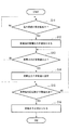
図3は、本実施の形態にかかる風力発電装置1において、電力系統13の周波数が低下した場合の制御の過程を示すフローチャートである。
FIG. 3 is a flowchart illustrating a control process when the frequency of the power system 13 is decreased in the
風力発電装置1では、センサ19により系統周波数が検出され、検出結果が制御装置20に出力される。図3のステップS11において、制御装置20では、センサ19からの出力に応答して、系統周波数が低下して、所定の定格値周波数以下となったか否かを判定する。系統周波数が定格周波数以下になっていないと判断された場合には、ステップS11の処理を繰り返し、引き続きセンサ19からの検出結果に対して所定の時間間隔で系統周波数が低下したか否かを判定する。ステップS11で系統周波数が所定の定格値周波数以下となったと判定された場合には、次のステップS12に進む。
In the
次のステップS12では、制御装置20が、系統周波数の低下に応答して、風力発電装置1に対してその発電出力を増加させるように制御する。発電出力を上昇させて系統周波数の変動を抑制することにより電力系統13を安定化させるためである。具体的には、主制御装置23が、発電出力を増加させるようにコンバータ制御装置21及びピッチ角制御部22に出力増加制御信号を出力する。そして、この出力増加制御信号に応答して、ピッチ角制御部22によりブレード8をそのピッチ角がファインとなるように制御する、又は、コンバータ制御装置21により、発電出力を増加させるよう発電機側インバータ14を制御する。
In the next step S12, the
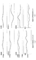
例えば、図4(a)に示すように、風速が定格風速付近である場合において、系統周波数が低下すると、主制御装置23が出力増加制御信号を出力する。ピッチ角制御部22は出力増加制御信号に応答し、ブレード8をそのピッチ角がファインとなるように制御して発電出力を増加させる。風速が低下してブレード8のピッチ角がファインであっても発電機5の回転数が低下し、ピッチ角制御では発電出力を定格値に維持するに足りない場合には、更に、コンバータ制御装置21により、ロータ慣性エネルギーを発電出力に変換して発電出力を増加させるよう発電機側インバータ14を制御する。
For example, as shown in FIG. 4A, when the wind speed is around the rated wind speed, the
また、図4(b)に示すように、風速が定格風速未満である場合においては、発電出力も定格値未満となっている。この場合において、通常は、ブレード8のピッチ角は既にファインとされているため、系統周波数が低下した場合は、コンバータ制御装置21により、ロータ慣性エネルギーを発電出力に変換して発電出力を増加させるよう発電機側インバータ14を制御する。
In addition, as shown in FIG. 4B, when the wind speed is less than the rated wind speed, the power generation output is also less than the rated value. In this case, normally, since the pitch angle of the
次のステップS13では、主制御部23が、センサ19から出力電流Igrid及び電圧Vgridの検出結果に応答して、電力系統13に出力される発電出力を算出し、算出結果である発電出力が所定の定格値以上であるか否かを判定する。この判定において、発電出力が所定の定格値未満である場合にはステップS15に進み、所定の定格値以上である場合にはステップS14に進む。ステップS14では、制御装置20により、ブレード8のピッチ角、発電機側インバータ14を制御することにより発電出力を定格値に維持する。
In the next step S13, the
ステップS15では、発電機5の回転数が下限値未満であるか否かを判定する。この判定において発電機5の回転数が下限値未満でないと判断された場合には、ステップS13に戻り上述した処理を繰り返し、発電機5の回転数が下限値未満であると判定された場合には、次のステップS16に進む。ステップS16では、発電機5の回転数が下限値未満となった場合に、更に回転数が減少すると風力発電装置1の運転が継続できなくなるため、これを避けるべく、制御装置20は発電出力を減少させるように風力発電装置1を制御することで、発電機5の回転数を上昇させ、本ルーチンを終了する。
In step S15, it is determined whether or not the rotational speed of the
図5は、本実施の形態にかかる風力発電装置1において、電力系統13の周波数が上昇した場合の制御の過程を示すフローチャートである。
FIG. 5 is a flowchart illustrating a control process when the frequency of the power system 13 is increased in the
風力発電装置1では、センサ19により系統周波数が検出され、検出結果が制御装置20に出力される。図5のステップS21において、制御装置20では、センサ19からの出力に応答して、系統周波数が上昇して、所定の定格値周波数以上となったか否かを判定する。系統周波数が定格周波数以上になっていないと判断された場合には、ステップS21の処理を繰り返し、引き続きセンサ19からの検出結果に対して所定の時間間隔で系統周波数が低下したか否かを判定する。ステップS21で系統周波数が所定の定格値周波数以上となったと判定された場合には、次のステップS22に進む。
In the
次のステップS22では、制御装置20が、系統周波数の上昇に応答して、風力発電装置1に対してその発電出力を減少させるように制御する。発電出力を減少させて系統周波数の変動を抑制することにより電力系統13を安定化させるためである。具体的には、主制御装置23が、発電出力を減少させるようにコンバータ制御装置21及びピッチ角制御部22に出力減少制御信号を出力する。そして、この出力減少制御信号に応答して、ピッチ角制御部22によりブレード8をそのピッチ角がフェザーとなるように制御する、又は、コンバータ制御装置21により、発電出力を減少させるよう発電機側インバータ14を制御する。
In the next step S22, the
例えば、図6(a)に示すように、風速が定格風速以上である場合において、系統周波数が上昇した場合は、ピッチ角制御部22により、出力減少制御信号に応答して、ブレード8をそのピッチ角がフェザーとなるように制御する。ブレード8のピッチ角がフェザーであっても十分に発電出力が減少しない場合又は更に出力を減少させたい場合には、発電出力を減少させるように発電機側インバータ14を制御する。
For example, as shown in FIG. 6A, in the case where the wind speed is equal to or higher than the rated wind speed, when the system frequency increases, the pitch
また、図6(b)に示すように、風速が定格風速未満である場合においては、発電出力も定格値未満となっている。この場合において、系統周波数が上昇した場合は、更に発電出力を減少させるように発電機側インバータ14を制御する。
In addition, as shown in FIG. 6B, when the wind speed is less than the rated wind speed, the power generation output is also less than the rated value. In this case, when the system frequency increases, the generator-
次のステップS23では、主制御部23が、センサ19から出力電流Igrid及び電圧Vgridの検出結果に応答して、電力系統13に出力される発電出力を算出し、算出結果である発電出力が所定の下限値以下であるか否かを判定する。この判定において、発電出力が所定の下限値以下であると判定された場合にはステップS25に進み、所定の下限値以下でないと判定された場合にはステップS24に進む。ステップS24では、制御装置20により、ブレード8のピッチ角、発電機側インバータ14を制御することにより発電出力を下限値に維持する。
In the next step S23, the
ステップS25では、発電機5の回転数が上限値以上であるか否かを判定する。ステップS22のインバータ制御は、発電機5の回転数が上昇する方向に作用するためである。この判定において発電機5の回転数が上限値以上でないと判定された場合には、ステップS23に戻り上述した処理を繰り返し、発電機5の回転数が上限値以上であると判定された場合には、次のステップS26に進む。ステップS26では、発電機5の回転数が上限値以上となった場合に、そのまま風力発電装置1の運転を継続すると過回転により発電装置が破損する虞があるため、これを避けるべく、回転数が低下するように、即ち制御装置20は発電出力を増加させるように発電機側インバータ14を制御し、本ルーチンを終了する。
In step S25, it is determined whether or not the rotational speed of the
尚、上述したように、系統周波数に変動があった場合に、発電出力を増加又は減少させるように制御したにも拘わらず、所定の時間が経過しても周波数が所定の定格周波数以下である場合、又は、所定の時間が経過しても周波数が所定の定格周波数以上である場合には、電力系統への影響を考慮して、風力発電装置1の運転を停止させる。
上述した実施形態においては、所定の定格周波数を基準に周波数の変動を判断する構成としたが、このような構成に限られることはなく、所定の定格周波数に対して許容範囲を定め、周波数が許容範囲内に入るか否かに基づいて周波数の変動を判断する構成とすることもできる。
In addition, as described above, when the system frequency varies, the frequency is not more than the predetermined rated frequency even if a predetermined time elapses even though the power generation output is controlled to increase or decrease. In the case where the frequency is equal to or higher than the predetermined rated frequency even after the predetermined time has elapsed, the operation of the
In the above-described embodiment, the frequency variation is determined based on the predetermined rated frequency. However, the present invention is not limited to such a configuration, and an allowable range is determined for the predetermined rated frequency, and the frequency is It is also possible to determine the frequency variation based on whether or not it falls within the allowable range.
このように、電力系統に周波数変動が発生した場合に、通常は発電出力は風況や発電機回転数に依存するところ、本実施形態によれば、幅広い風況・発電機回転数条件下で、電力系統の周波数の変動に対応して、風力発電装置の発電出力を任意に増加又は減少させることにより、電力系統の安定化を図ることができる。 Thus, when frequency fluctuations occur in the power system, the power generation output usually depends on the wind conditions and the generator rotation speed.According to this embodiment, under a wide range of wind conditions and generator rotation speed conditions, The power system can be stabilized by arbitrarily increasing or decreasing the power generation output of the wind turbine generator in response to fluctuations in the frequency of the power system.
なお、上述した本実施形態においては、発電機5として所謂巻線型誘導発電機を用いると共に、発電機側インバータ14、DCバス15、及び系統側インバータ16から構成されるインバータ装置17を用い、発電機5のステータ巻線が電力系統13に直接に接続され、ロータ巻線がインバータ装置17を介して電力系統13に接続される構成とした(図2参照)。この場合、発電機の固定子巻線が直接電力系統と接続されているため、電力系統の周波数が変動すれば、発電機出力に直接影響が生じる。
一方、上述した構成のみならず、図7に示すように、発電機として多極同期発電機を用い、そのステータ巻線がインバータとコンバータからなるインバータ装置を介して電力系統に接続される構成とすることもできる。
このような構成では、発電機と電力系統がインバータ装置を介して接続されているため、電力系統の周波数変動は発電機に影響を与えない。すなわち、電力系統の周波数が変動したときの発電機側インバータの制御は上述した図2に示す発電機5の構成に比べると容易となる。
In the above-described embodiment, a so-called winding induction generator is used as the
On the other hand, as shown in FIG. 7 as well as the above-described configuration, a multi-pole synchronous generator is used as a generator, and the stator winding is connected to the power system via an inverter device composed of an inverter and a converter. You can also
In such a configuration, since the generator and the power system are connected via the inverter device, the frequency fluctuation of the power system does not affect the generator. That is, the control of the generator-side inverter when the frequency of the power system fluctuates becomes easier as compared with the configuration of the
〔第二の実施形態〕
次に、本発明の第二の実施形態について、図8又は図9を用いて説明する。
本実施形態は、上述した第一の実施形態に係る風力発電装置1が複数設けられた、ウィンドパークないしはウィンドファームと称される風力発電システムに関する。本実施形態の風力発電システムは、複数の風力発電装置1と、この複数の風力発電装置1と制御信号等の情報を送受信可能なように通信ラインで相互に接続され、各風力発電装置を管理・制御する管理制御装置を備えている。
[Second Embodiment]
Next, a second embodiment of the present invention will be described with reference to FIG. 8 or FIG.
The present embodiment relates to a wind power generation system called a wind park or wind farm, in which a plurality of wind
管理制御装置としては、CPU(中央演算装置)、ROM(Read Only Memory)、RAM(Random Access Memory)等を備えた汎用又は専用のコンピュータ及びこのコンピュータ上で動作するプログラムを利用して実現することができる。この場合、CPU等により、上記処理の全て或いは一部を実現させるためのプログラムが記録されたコンピュータ読み取り可能な記録媒体に記録されているプログラムを読み出して、プログラムをROMやRAMなどに展開し、情報の加工・演算処理を実行することにより、管理制御装置として機能し、風力発電装置を管理・制御する。 The management control device is realized by using a general-purpose or dedicated computer having a CPU (Central Processing Unit), a ROM (Read Only Memory), a RAM (Random Access Memory), etc., and a program operating on the computer. Can do. In this case, the CPU or the like reads out a program recorded on a computer-readable recording medium on which a program for realizing all or part of the above processing is recorded, and expands the program in a ROM or RAM. By executing information processing / arithmetic processing, it functions as a management control device, and manages and controls the wind turbine generator.
ここでコンピュータ読み取り可能な記録媒体とは、磁気ディスク、光磁気ディスク、CD−ROM、DVD−ROM、半導体メモリ等をいう。また、このコンピュータプログラムを通信回線によってコンピュータに配信し、この配信を受けたコンピュータが当該プログラムを実行するようにしても良い。 Here, the computer-readable recording medium means a magnetic disk, a magneto-optical disk, a CD-ROM, a DVD-ROM, a semiconductor memory, or the like. Alternatively, the computer program may be distributed to the computer via a communication line, and the computer that has received the distribution may execute the program.
以下に、図8及び図9を参照して、風力発電システムにおける制御方法について説明する。 Below, with reference to FIG.8 and FIG.9, the control method in a wind power generation system is demonstrated.
図8は、本実施の形態にかかる風力発電システムにおいて、電力系統の周波数が低下した場合の制御の過程を示すフローチャートである。
ステップS31において、管理制御装置では、系統周波数を検出し、系統周波数が所定の定格値以下となったことを検出し、次のステップS32に進む。なお、系統周波数の検出は、各風力発電装置に設けられたセンサからの出力に基づくものでもよく、また管理制御装置が独自に系統周波数を検出するセンサを備えていてもよいし、電力系統を管理する電力会社からの指令をこれに換えても良い。
FIG. 8 is a flowchart showing a control process when the frequency of the power system is lowered in the wind power generation system according to the present embodiment.
In step S31, the management control device detects the system frequency, detects that the system frequency is equal to or lower than a predetermined rated value, and proceeds to the next step S32. The detection of the system frequency may be based on an output from a sensor provided in each wind power generator, or the management control device may be provided with a sensor for detecting the system frequency independently. You may change the command from the electric power company to manage to this.
次のステップS32では、管理制御装置が、系統周波数の低下に応答して、風力発電システムの発電出力を増加させる旨決定し、次のステップS33に進む。発電出力を上昇させて系統周波数の変動を抑制することにより電力系統を安定化させるためである。ステップS33では、管理制御装置から、管理制御装置と接続された全ての風力発電装置1に対して、各風力発電装置1の発電出力を増加させるための発電増指令(第一の制御信号)を送信する。
ステップS34では、各風力発電装置1の制御装置20が管理制御装置からの発電増指令を受信し、この発電増指令に応答して、自己の発電出力を増加させるように制御する。具体的には、上述した第一の実施形態における風力発電装置1と同様に、ピッチ角制御部22によりブレード8をそのピッチ角がファインとなるように制御する、又は、コンバータ制御装置21により、発電出力を増加させるよう発電機側インバータ14を制御する。
In the next step S32, the management control device determines to increase the power generation output of the wind power generation system in response to the decrease in the system frequency, and proceeds to the next step S33. This is to stabilize the power system by increasing the power generation output and suppressing fluctuations in the system frequency. In step S33, a power generation increase command (first control signal) for increasing the power generation output of each
In step S34, the
次のステップS35では、風力発電装置1の主制御部23が、センサ19から出力電流Igrid及び電圧Vgridの検出結果に応答して、電力系統13に出力される発電出力を算出し、算出結果である発電出力が所定の定格値以上であるか否かを判定する。この判定において、発電出力が所定の定格値未満である場合にはステップS37に進み、所定の定格値以上である場合にはステップS36に進む。ステップS36では、制御装置20により、ブレード8のピッチ角、発電機側インバータ14を制御することにより発電出力を上限値(定格値)に固定する。
In the next step S35, the
ステップS37では、発電機5の回転数が下限値未満であるか否かを判定する。この判定において発電機5の回転数が下限値未満でないと判断された場合には、ステップS35に戻り上述した処理を繰り返し、発電機5の回転数が下限値未満であると判定された場合には、次のステップS38に進む。ステップS38では、発電機5の回転数が下限値未満となった場合に、更に回転数が低下すると風力発電装置1の運転が継続できなくなるため、これを避けるべく、制御装置20は発電出力を減少させるように風力発電装置1を制御する。制御装置20は、風力発電装置1の発電出力を減少させた場合には、その情報を管理制御装置に送信する。
In step S37, it is determined whether the rotation speed of the
ステップS39では、管理制御装置が各風力発電装置1からの発電出力を減少させた旨の情報を受けて、全ての風力発電装置1の発電出力が減少したか否かを判定する。この判定は、全ての風力発電装置1の発電出力が減少するまで繰り返され、全ての風力発電装置の発電出力が減少したと判定された場合に、次のステップS40に進む。ステップS40では、全ての風力発電装置1の発電出力が減少したことに応答して、全ての風力発電装置1に対して、ステップS33で送信した発電増指令を解除する旨の、解除指令を送信し、本ルーチンを終了する。
In step S39, the management control device receives information indicating that the power generation output from each wind
図9は、本実施の形態にかかる風力発電システムにおいて、電力系統の周波数が上昇した場合の制御の過程を示すフローチャートである。 FIG. 9 is a flowchart illustrating a control process when the frequency of the power system is increased in the wind power generation system according to the present embodiment.
ステップS41において、管理制御装置では、系統周波数を検出し、系統周波数が所定の定格値以上となったことを検出し、次のステップS42に進む。なお、系統周波数の検出は、各風力発電装置に設けられたセンサからの出力に基づくものでもよく、また管理制御装置が独自に系統周波数を検出するセンサを備えていてもよいし、電力系統を管理する電力会社からの指令をこれに換えても良い。 In step S41, the management control device detects the system frequency, detects that the system frequency is equal to or higher than a predetermined rated value, and proceeds to the next step S42. The detection of the system frequency may be based on an output from a sensor provided in each wind power generator, or the management control device may be provided with a sensor for detecting the system frequency independently. You may change the command from the electric power company to manage to this.
次のステップS42では、管理制御装置が、系統周波数の上昇に応答して、風力発電システムの発電出力を減少させる旨決定し、次のステップS43に進む。系統周波数を低下させて系統周波数の変動を抑制することにより電力系統を安定化させるためである。ステップS43では、管理制御装置から、管理制御装置と接続された全ての風力発電装置1に対して、各風力発電装置1の発電出力を低下させるための発電減指令(第二の制御信号)を送信する。
ステップS44では、各風力発電装置1の制御装置20が管理制御装置からの発電減指令を受信し、この発電減指令に応答して、自己の発電出力を減少させるように制御する。具体的には、上述した第一の実施形態における風力発電装置1と同様に、ピッチ角制御部22によりブレード8をそのピッチ角がフェザーとなるように制御する、又は、コンバータ制御装置21により、発電出力を減少させるよう発電機側インバータ14を制御する。
In the next step S42, the management control device determines to reduce the power generation output of the wind power generation system in response to the increase in the system frequency, and proceeds to the next step S43. This is because the power system is stabilized by lowering the system frequency and suppressing the fluctuation of the system frequency. In step S43, a power generation reduction command (second control signal) for reducing the power generation output of each
In step S44, the
次のステップS45では、風力発電装置1の主制御部23が、センサ19から出力電流Igrid及び電圧Vgridの検出結果に応答して、電力系統13に出力される発電出力を算出し、算出結果である発電出力が所定の下限値以上であるか否かを判定する。この判定において、発電出力が所定の下限値未満である場合にはステップS47に進み、所定の下限値以上である場合にはステップS46に進む。ステップS46では、制御装置20により、ブレード8のピッチ角、発電機側インバータ14を制御することにより発電出力を下限値に固定する。
In the next step S45, the
ステップS47では、発電機5の回転数が上限値以上であるか否かを判定する。この判定において発電機5の回転数が上限値以上でないと判断された場合には、ステップS45に戻り上述した処理を繰り返し、発電機5の回転数が上限値以上であると判定された場合には、次のステップS48に進む。ステップS48では、発電機5の回転数が上限値以上となった場合に、更に回転数が上昇すると風力発電装置1が破損する虞があるため、これを避けるべく、制御装置20は発電出力を増加させるように風力発電装置1を制御する。制御装置20は、風力発電装置1の発電出力を増加させた場合には、その情報を管理制御装置に送信する。
In step S47, it is determined whether or not the rotational speed of the
ステップS49では、管理制御装置が各風力発電装置1からの発電出力を増加させた旨の情報を受けて、全ての風力発電装置1の発電出力が増加したか否かを判定する。この判定は、全ての風力発電装置1の発電出力が増加するまで繰り返され、全ての風力発電装置の発電出力が増加したと判定された場合に、次のステップS50に進む。ステップS50では、全ての風力発電装置1の発電出力が減少したことに応答して、全ての風力発電装置1に対して、ステップS43で送信した発電減指令を解除する旨の、解除指令を送信し、本ルーチンを終了する。
In step S49, the management control device receives information indicating that the power generation output from each wind
なお、解除指令は、系統周波数が回復し定格周波数となった場合、あるいは、所定の時間が経過した場合に送信される構成とすることもできる。また、上述した実施形態においては、管理制御装置からの発電増指令又は発電減指令等の制御信号は、全ての風力発電装置に対して送信していたが、必ずしもこのような構成である必要はなく、一部の風力発電装置に対して送信する構成とすることもできる。
さらに、各風力発電装置が、管理制御装置からの発電増指令又は発電減指令を受信したことにより、これらの指令に従って直ちに発電出力を制御する構成とすることができる。この他、各風力発電装置が、管理制御装置からの発電増指令又は発電減指令に基づいて、夫々自己の風力発電装置の制御装置において発電出力の制御を行うか否かを判断する構成とすることもできる。
上述した実施形態においては、所定の定格周波数を基準に周波数の変動を判断する構成としたが、このような構成に限られることはなく、所定の定格周波数に対して許容範囲を定め、周波数が許容範囲内に入るか否かに基づいて周波数の変動を判断する構成とすることもできる。
Note that the release command may be transmitted when the system frequency recovers to become the rated frequency, or when a predetermined time has elapsed. Further, in the above-described embodiment, the control signal such as the power generation increase command or the power generation decrease command from the management control device is transmitted to all the wind power generation devices, but it is not always necessary to have such a configuration. It can also be set as the structure transmitted with respect to some wind power generators.
Furthermore, when each wind power generator receives a power generation increase command or a power generation decrease command from the management control device, the power generation output can be immediately controlled according to these commands. In addition, each wind turbine generator is configured to determine whether to control the power generation output in the control device of its own wind turbine generator based on the power generation increase command or the power generation decrease command from the management controller. You can also.
In the above-described embodiment, the frequency variation is determined based on the predetermined rated frequency. However, the present invention is not limited to such a configuration, and an allowable range is determined for the predetermined rated frequency, and the frequency is It is also possible to determine the frequency variation based on whether or not it falls within the allowable range.
このように、本実施形態によれば、電力系統に周波数変動が発生した場合に、幅広い風況・発電機回転数条件下で、電力系統の周波数の変動に対応して、複数の風力発電装置を備える風力発電システムの発電出力を任意に増加又は減少させることにより、電力系統の安定化を図ることができる。 As described above, according to the present embodiment, when a frequency variation occurs in the power system, a plurality of wind power generators can be used in response to the frequency variation of the power system under a wide range of wind conditions and generator speed conditions. The power system can be stabilized by arbitrarily increasing or decreasing the power generation output of the wind power generation system including the power generation system.
1 風力発電装置
2 タワー
3 ナセル
5 発電機
6 増速機
7 風車ロータ
8 ブレード
9 ハブ
13 電力系統
14 発電機側インバータ
15 DCバス
16 系統側インバータ
17 インバータ装置
18 PLG
19 センサ
20 制御装置
21 コンバータ制御部
22 ピッチ制御部
23 主制御部
DESCRIPTION OF
19
Claims (12)
前記ロータの回転により駆動される発電機と、
インバータ装置と、
電力系統の周波数が所定の定格周波数以下となった場合であって、かつ、前記発電機の回転数が第一の所定値以上である場合に、前記インバータ装置を制御し、前記ロータの慣性エネルギーを発電出力に変換・回収することで、前記回転数の減少を伴いつつ、前記発電機の前記発電出力を増加させるように制御する制御装置と、を備えたことを特徴とする風力発電装置。 A rotor rotating by wind power,
A generator driven by rotation of the rotor;
An inverter device;
When the frequency of the electric power system is equal to or lower than a predetermined rated frequency and the rotational speed of the generator is equal to or higher than a first predetermined value, the inverter device is controlled, and the inertia energy of the rotor the by converting and recovering the power generation output, the while with the rotational speed of the reduction, a wind power generation apparatus characterized by comprising a control device for controlling so as to increase the power output of the generator .
前記ロータの回転により駆動される発電機と、
インバータ装置と、
電力系統の周波数が所定の定格周波数以上となった場合であって、且つ、前記発電機の回転数が第二の所定値未満である場合に、前記インバータ装置を制御し、前記風力を前記ロータの慣性エネルギーに変換・保存することで、前記回転数の増加を伴いつつ、前記発電機の前記発電出力を減少させるように制御する制御装置と、を備えたことを特徴とする風力発電装置。 A rotor rotating by wind power,
A generator driven by rotation of the rotor;
An inverter device;
When the frequency of the electric power system is equal to or higher than a predetermined rated frequency and when the rotational speed of the generator is less than a second predetermined value, the inverter device is controlled, and the wind power is supplied to the rotor of by converting and storing the inertial energy, the while accompanied by an increase in rotational speed, the generator of the generator output wind power generator, characterized in that it and a control device for controlling so as to decrease little of the .
電力系統の周波数が所定の定格周波数以下となった場合であって、かつ、前記発電機の回転数が第一の所定値以上である場合に、前記インバータ装置を制御し、前記ロータの慣性エネルギーを発電出力に変換・回収することで、前記回転数の減少を伴いつつ、前記発電機の前記発電出力を増加させるように制御することを特徴とする風力発電装置の制御方法。 A method for controlling an air volume power generation device comprising: a rotor rotating by wind power; a generator driven by rotation of the rotor; and an inverter device .
When the frequency of the electric power system is equal to or lower than a predetermined rated frequency and the rotational speed of the generator is equal to or higher than a first predetermined value, the inverter device is controlled, and the inertia energy of the rotor the by converting and recovering the power generation output, a control method of a wind power generation apparatus, characterized in that the while with the rotational speed of the reduction, controls to increase the power output of the generator.
電力系統の周波数が所定の定格周波数以上となった場合であって、かつ、前記発電機の回転数が第二の所定値未満である場合に、前記インバータ装置を制御し、前記風力を前記ロータの慣性エネルギーに変換・保存することで、前記回転数の増加を伴いつつ、前記発電機の前記発電出力を減少させるように制御することを特徴とする風力発電装置の制御方法。 A wind power generator control method comprising: a rotor rotated by wind power ; a generator driven by rotation of the rotor; and an inverter device ,
When the frequency of the electric power system is equal to or higher than a predetermined rated frequency and when the rotational speed of the generator is less than a second predetermined value, the inverter device is controlled, and the wind power is supplied to the rotor the method of to convert and store the inertial energy, wind power generation apparatus, characterized in that the while accompanied by an increase in rotational speed is controlled to decrease to less of the power generation output of the generator.
前記複数の風力発電装置に対して所定の制御信号を送信することにより前記複数の風力発電装置を制御する管理制御装置と、を備え、
前記管理制御装置は、電力系統の周波数が所定の定格周波数以下となった場合に、前記風力発電装置に対して発電出力を増加させる第一の制御信号を送信し、
前記各風力発電装置は、前記第一の制御信号に応答して、自己の前記発電機の回転数が第一の所定値以上である場合に、前記インバータ装置を制御し、前記ロータの慣性エネルギーを発電出力に変換・回収することで、前記回転数の減少を伴いつつ、前記発電機の前記発電出力を増加させることを特徴とする風力発電システム。 A plurality of wind power generators having a rotor rotated by wind power , a generator driven by the rotation of the rotor, and an inverter device ;
A management control device that controls the plurality of wind turbine generators by transmitting a predetermined control signal to the plurality of wind turbine generators,
The management control device transmits a first control signal for increasing the power generation output to the wind power generator when the frequency of the power system becomes a predetermined rated frequency or less,
In response to the first control signal, each of the wind turbine generators controls the inverter device when the rotation speed of the generator is equal to or greater than a first predetermined value, and the inertia energy of the rotor the by converting and recovering the power generation output, the wind power generation system characterized by the while with the rotational speed of the reduction, thereby increasing the power output of the generator.
前記複数の風力発電装置に対して所定の制御信号を送信することにより前記複数の風力発電装置を制御する管理制御装置と、を備え、
前記管理制御装置は、電力系統の周波数が所定の定格周波数以上となった場合に、前記風力発電装置に対して発電出力を減少させる第二の制御信号を送信し、
前記各風力発電装置は、前記第二の制御信号に応答して、自己の前記発電機の回転数が第二の所定値未満である場合に、前記インバータ装置を制御し、前記風力を前記ロータの慣性エネルギーに変換・保存することで、前記回転数の増加を伴いつつ、前記発電機の前記発電出力を減少させることを特徴とする風力発電システム。 A plurality of wind power generators having a rotor rotated by wind power , a generator driven by the rotation of the rotor, and an inverter device ;
A management control device that controls the plurality of wind turbine generators by transmitting a predetermined control signal to the plurality of wind turbine generators,
The management control device transmits a second control signal for reducing the power generation output to the wind power generator when the frequency of the power system is equal to or higher than a predetermined rated frequency,
In response to the second control signal, each of the wind power generators controls the inverter device when the rotation speed of the generator is less than a second predetermined value, and the wind power is transmitted to the rotor. of by converting and storing the inertial energy, the while accompanied by an increase in rotational speed, the wind power generation system characterized in that to decrease little of the power generation output of the generator.
前記管理制御装置により、電力系統の周波数が所定の定格周波数以下となった場合に、前記風力発電装置に対して発電出力を増加させる第一の制御信号を送信するステップと、
前記各風力発電装置により、前記第一の制御信号に応答して、自己の前記発電機の回転数が第一の所定値以上である場合に、前記インバータ装置を制御し、前記ロータの慣性エネルギーを発電出力に変換・回収することで、前記回転数の減少を伴いつつ、前記発電機の前記発電出力を増加させるステップと、を備えたことを特徴とする風力発電システムの制御方法。 By transmitting a predetermined control signal to the plurality of wind power generators, a plurality of wind power generators having a rotor that is rotated by wind power, a generator that is driven by the rotation of the rotor, and an inverter device A management control device for controlling the plurality of wind turbine generators, and a method for controlling a wind turbine generator system comprising:
A step of transmitting a first control signal for increasing the power generation output to the wind power generator when the frequency of the power system is equal to or lower than a predetermined rated frequency by the management control device;
In response to the first control signal, each of the wind turbine generators controls the inverter device when the rotation speed of the generator is equal to or greater than a first predetermined value, and the inertia energy of the rotor the by converting and recovering the power generation output, albeit with a reduction of the rotational speed, control method of a wind power generation system characterized by comprising the steps of: to increase the power output of the generator.
前記管理制御装置により、電力系統の周波数が所定の定格周波数以上となった場合に、前記風力発電装置に対して発電出力を減少させる第二の制御信号を送信するステップと、
前記各風力発電装置は、前記第二の制御信号に応答して、自己の前記発電機の回転数が第二の所定値未満である場合に、前記インバータ装置を制御し、前記風力を前記ロータの慣性エネルギーに変換・保存することで、前記回転数の増加を伴いつつ、前記発電機の前記発電出力を減少させるステップと、を供えたことを特徴とする風力発電システムの制御方法。 By transmitting a predetermined control signal to the plurality of wind power generators, a plurality of wind power generators having a rotor that is rotated by wind power, a generator that is driven by the rotation of the rotor, and an inverter device A management control device for controlling the plurality of wind turbine generators, and a method for controlling a wind turbine generator system comprising:
A step of transmitting a second control signal for reducing the power generation output to the wind power generator when the frequency of the power system is equal to or higher than a predetermined rated frequency by the management control device;
In response to the second control signal, each of the wind power generators controls the inverter device when the rotation speed of the generator is less than a second predetermined value, and the wind power is transmitted to the rotor. of by converting and storing the inertial energy, while accompanied by an increase in the rotational speed, control method of a wind power generation system, comprising the, steps to decrease little of the power generation output of the generator.
Priority Applications (8)
| Application Number | Priority Date | Filing Date | Title |
|---|---|---|---|
| JP2009183532A JP5550283B2 (en) | 2009-08-06 | 2009-08-06 | Wind turbine generator, wind turbine generator control method, wind turbine generator system, and wind turbine generator system control method |
| EP10806278.7A EP2463519B2 (en) | 2009-08-06 | 2010-05-21 | Wind turbine generator, control method for wind turbine generator, wind turbine generator system, and control method for wind turbine generator system |
| AU2010280169A AU2010280169A1 (en) | 2009-08-06 | 2010-05-21 | Wind-power generation device, control method for wind-power generation device, wind-power generation system, and control method for wind-power generation system |
| PCT/JP2010/058619 WO2011016278A1 (en) | 2009-08-06 | 2010-05-21 | Wind-power generation device, control method for wind-power generation device, wind-power generation system, and control method for wind-power generation system |
| CN201080025811.7A CN102472249B (en) | 2009-08-06 | 2010-05-21 | Wind turbine generator, control method for wind turbine generator, wind turbine generator system, and control method for wind turbine generator system |
| KR1020117028946A KR20120025499A (en) | 2009-08-06 | 2010-05-21 | Wind-power generation device, control method for wind-power generation device, wind-power generation system, and control method for wind-power generation system |
| US12/845,984 US8378643B2 (en) | 2009-08-06 | 2010-07-29 | Wind turbine generator, control method for wind turbine generator, wind turbine generator system, and control method for wind turbine generator system |
| US13/768,538 US20130193934A1 (en) | 2009-08-06 | 2013-02-15 | Wind turbine generator, control method for wind turbine generator, wind turbine generator system, and control method for wind turbine generator system |
Applications Claiming Priority (1)
| Application Number | Priority Date | Filing Date | Title |
|---|---|---|---|
| JP2009183532A JP5550283B2 (en) | 2009-08-06 | 2009-08-06 | Wind turbine generator, wind turbine generator control method, wind turbine generator system, and wind turbine generator system control method |
Publications (3)
| Publication Number | Publication Date |
|---|---|
| JP2011038406A JP2011038406A (en) | 2011-02-24 |
| JP2011038406A5 JP2011038406A5 (en) | 2012-09-20 |
| JP5550283B2 true JP5550283B2 (en) | 2014-07-16 |
Family
ID=43534248
Family Applications (1)
| Application Number | Title | Priority Date | Filing Date |
|---|---|---|---|
| JP2009183532A Active JP5550283B2 (en) | 2009-08-06 | 2009-08-06 | Wind turbine generator, wind turbine generator control method, wind turbine generator system, and wind turbine generator system control method |
Country Status (7)
| Country | Link |
|---|---|
| US (2) | US8378643B2 (en) |
| EP (1) | EP2463519B2 (en) |
| JP (1) | JP5550283B2 (en) |
| KR (1) | KR20120025499A (en) |
| CN (1) | CN102472249B (en) |
| AU (1) | AU2010280169A1 (en) |
| WO (1) | WO2011016278A1 (en) |
Families Citing this family (46)
| Publication number | Priority date | Publication date | Assignee | Title |
|---|---|---|---|---|
| KR20070026362A (en) * | 2004-02-27 | 2007-03-08 | 미츠비시 쥬고교 가부시키가이샤 | Wind turbine generator, active vibration damping method for the same, and wind turbine tower |
| EP2339743B1 (en) * | 2008-10-16 | 2018-07-25 | Mitsubishi Heavy Industries, Ltd. | Wind power generation system, and its control method |
| JP5320311B2 (en) * | 2010-01-18 | 2013-10-23 | 三菱重工業株式会社 | Variable speed generator and control method thereof |
| CN103097726B (en) * | 2010-08-13 | 2015-10-21 | 维斯塔斯风力系统集团公司 | The wind-powered electricity generation with the power fluctuation of reduction is produced |
| US20120104753A1 (en) * | 2010-10-29 | 2012-05-03 | Mitsubishi Heavy Industries, Ltd. | Control system of wind power generator, wind farm, and method for controlling wind power generator |
| DK2458205T3 (en) * | 2010-11-26 | 2017-01-30 | Siemens Ag | Method and system for controlling an electric device of a wind turbine |
| JP5455890B2 (en) * | 2010-12-28 | 2014-03-26 | 三菱重工業株式会社 | Wind turbine generator control device, wind turbine generator system, and wind turbine generator control method |
| JP2012143079A (en) | 2010-12-28 | 2012-07-26 | Mitsubishi Heavy Ind Ltd | Cable supporter |
| AU2011202420A1 (en) * | 2011-02-23 | 2012-09-06 | Mitsubishi Heavy Industries, Ltd. | Controller for wind turbine generator, wind turbine generator, and method of controlling wind turbine generator |
| BRPI1100051A2 (en) | 2011-02-28 | 2016-05-03 | Mitsubishi Heavy Ind Ltd | wind turbine generator, and method for controlling to control a wind turbine generator. |
| DE102011006670A1 (en) * | 2011-04-01 | 2012-10-04 | Aloys Wobben | Wind energy plant and method for operating a wind energy plant |
| CN103717886B (en) * | 2011-06-30 | 2016-08-24 | 维斯塔斯风力系统集团公司 | For controlling the system and method for the power exported from wind turbine or wind power plant |
| EP2776711A4 (en) * | 2011-07-21 | 2015-08-05 | Vestas Wind Sys As | Method of operating wind turbine and controller thereof |
| EP2557678B1 (en) * | 2011-08-09 | 2014-05-07 | Siemens Aktiengesellschaft | Arrangement for generating a control signal for controlling an acceleration of a generator |
| AU2011319719A1 (en) | 2011-08-10 | 2013-02-28 | Mitsubishi Heavy Industries, Ltd. | Control device for wind power plant and control method for wind power plant |
| CN102305180B (en) * | 2011-08-31 | 2013-07-31 | 国电联合动力技术有限公司 | Control method and system of differential gear box speed regulation type synchro wind generating set |
| ES2562655T3 (en) * | 2011-09-30 | 2016-03-07 | Vestas Wind Systems A/S | Fast reverse control that includes plant losses |
| JP2013087703A (en) * | 2011-10-19 | 2013-05-13 | Mitsubishi Heavy Ind Ltd | Wind power generation device and method for the same, and program therefor |
| CN102506477B (en) * | 2011-10-23 | 2014-01-29 | 西安交通大学 | Heat and power cogeneration unit and wind power generation combined refrigeration system and scheduling method thereof |
| US8736094B2 (en) | 2012-01-20 | 2014-05-27 | Mitsubishi Heavy Industries, Ltd. | Wind-turbine-generator control system, wind turbine generator, wind farm, and wind-turbine-generator control method |
| JP5713927B2 (en) * | 2012-01-20 | 2015-05-07 | 三菱重工業株式会社 | Wind turbine generator control device, wind turbine generator, wind farm, and wind turbine generator control method |
| WO2013125044A1 (en) * | 2012-02-24 | 2013-08-29 | 三菱重工業株式会社 | Wind turbine control device and method, and wind power generation system |
| JP5272113B1 (en) * | 2012-02-24 | 2013-08-28 | 三菱重工業株式会社 | Wind power generation system, control device therefor, and control method therefor |
| JP5245017B1 (en) * | 2012-02-24 | 2013-07-24 | 三菱重工業株式会社 | Wind power generation system and control method thereof |
| DE102012203334A1 (en) * | 2012-03-02 | 2013-09-05 | Wobben Properties Gmbh | Method for operating a combined cycle power plant or combined cycle power plant |
| CN104285059B (en) | 2012-05-11 | 2017-03-01 | 维斯塔斯风力系统集团公司 | Wind power plant's FREQUENCY CONTROL |
| US20130320937A1 (en) * | 2012-06-05 | 2013-12-05 | General Electric Company | System and method to stabilize power supply |
| DE102012215575A1 (en) | 2012-09-03 | 2014-03-06 | Wobben Properties Gmbh | Method and control device for a wind energy plant and computer program product, digital storage medium and wind energy plant |
| EP2708737B1 (en) * | 2012-09-12 | 2020-10-28 | General Electric Technology GmbH | Method for operating a thermal power plant |
| US9450416B2 (en) * | 2013-07-16 | 2016-09-20 | Siemens Aktiengesellschaft | Wind turbine generator controller responsive to grid frequency change |
| US9115695B2 (en) * | 2013-07-16 | 2015-08-25 | Siemens Aktiengesellschaft | Method and arrangement for controlling a wind turbine |
| ES2545674B1 (en) * | 2014-03-11 | 2016-06-29 | Gamesa Innovation & Technology, S.L. | Inertia control system for wind turbines |
| JP2016013039A (en) * | 2014-06-30 | 2016-01-21 | 住友電気工業株式会社 | Power transmission system, and operation method for power transmission system |
| KR101564978B1 (en) * | 2014-07-15 | 2015-11-02 | 전북대학교산학협력단 | Method for adaptive inertial control in a wind turbine |
| KR20160080830A (en) | 2014-12-29 | 2016-07-08 | 노츠 주식회사 | Renewable energy harvesting apparatus and system using piping) |
| EP3303833A1 (en) | 2015-06-03 | 2018-04-11 | Vestas Wind Systems A/S | Overboosting techniques for wind power plant |
| JP6276223B2 (en) * | 2015-07-16 | 2018-02-07 | 株式会社日本製鋼所 | Wind power generation device, wind power generation control device, and wind power generation control program |
| DE102016106215A1 (en) | 2016-04-05 | 2017-10-05 | Wobben Properties Gmbh | Method and wind turbine for feeding electrical power |
| US10074985B2 (en) * | 2016-06-21 | 2018-09-11 | The Aerospace Corporation | Solar and/or wind inverter |
| WO2018095493A1 (en) * | 2016-11-25 | 2018-05-31 | Vestas Wind Systems A/S | A method of controlling a wind turbine, a controller for a wind turbine and a wind turbine |
| CN109931217B (en) * | 2017-12-15 | 2020-05-12 | 新疆金风科技股份有限公司 | Wind generating set shutdown control method and system |
| CN110098622B (en) * | 2018-01-31 | 2021-04-13 | 北京金风科创风电设备有限公司 | Primary frequency modulation method and device for wind turbine generator |
| KR102225611B1 (en) * | 2019-06-18 | 2021-03-12 | 연세대학교 산학협력단 | Control System and Method of Renewable Energy Generator for Improving Frequency Stability |
| JP7379062B2 (en) * | 2019-10-04 | 2023-11-14 | 株式会社東芝 | Power control device and power control system |
| US11754056B1 (en) | 2021-03-26 | 2023-09-12 | Hawk Spider Energy Corp. | Dynamic mass torque generator |
| KR102539829B1 (en) * | 2021-07-14 | 2023-06-02 | 연세대학교 산학협력단 | Method for controlling inertia of power plant and inertia control system using the same |
Family Cites Families (22)
| Publication number | Priority date | Publication date | Assignee | Title |
|---|---|---|---|---|
| JPS61240900A (en) * | 1985-04-15 | 1986-10-27 | Oriental Kiden Kk | Windmill generator |
| US5083039B1 (en) * | 1991-02-01 | 1999-11-16 | Zond Energy Systems Inc | Variable speed wind turbine |
| JP3002160B2 (en) * | 1997-08-13 | 2000-01-24 | 利雄 岩田 | Ventilation and power generation method and device |
| JPH1169893A (en) * | 1997-08-26 | 1999-03-09 | Hitachi Eng & Services Co Ltd | Hybrid power generation system |
| DE10022974C2 (en) | 2000-05-11 | 2003-10-23 | Aloys Wobben | Method for operating a wind energy plant and wind energy plant |
| JP4056713B2 (en) * | 2001-03-26 | 2008-03-05 | 株式会社MERSTech | Wind power generation equipment |
| ES2189664B1 (en) | 2001-09-13 | 2004-10-16 | Made Tecnologias Renovables, S.A. | SYSTEM FOR THE USE OF THE ENERGY STORED IN THE MECHANICAL INERTIA OF THE ROTOR OF A WIND TURBINE. |
| AU2002368205A1 (en) * | 2002-09-13 | 2004-04-30 | Abb Ab | Wind power fed network |
| EP1467463B1 (en) * | 2003-04-09 | 2016-12-21 | General Electric Company | Wind farm and method for operating same |
| US7528496B2 (en) | 2003-09-03 | 2009-05-05 | Repower Systems Ag | Method for operating or controlling a wind turbine and method for providing primary control power by means of wind turbines |
| GB2407440B (en) * | 2003-09-23 | 2006-02-22 | Responsiveload Ltd | Grid stabilising system |
| US7504738B2 (en) | 2005-09-29 | 2009-03-17 | General Electric Company | Wind turbine and method for operating same |
| US7345373B2 (en) | 2005-11-29 | 2008-03-18 | General Electric Company | System and method for utility and wind turbine control |
| EP1914419B1 (en) * | 2006-10-19 | 2015-09-16 | Siemens Aktiengesellschaft | Wind energy installation and method of controlling the output power from a wind energy installation |
| US9020650B2 (en) * | 2007-02-13 | 2015-04-28 | General Electric Company | Utility grid, controller, and method for controlling the power generation in a utility grid |
| CN100464493C (en) * | 2007-03-13 | 2009-02-25 | 西安理工大学 | Pneumatic generating speed-changing frequency-constant method and apparatus based on digital-controlled flywheel hybrid driven |
| JP5198791B2 (en) * | 2007-05-07 | 2013-05-15 | 株式会社日立製作所 | Wind power generation system, control method therefor, and wind power plant using the same |
| US8237301B2 (en) | 2008-01-31 | 2012-08-07 | General Electric Company | Power generation stabilization control systems and methods |
| JP4698718B2 (en) * | 2008-09-30 | 2011-06-08 | 株式会社日立製作所 | Wind turbine generator group control device and control method |
| DE102009014012B4 (en) * | 2009-03-23 | 2014-02-13 | Wobben Properties Gmbh | Method for operating a wind energy plant |
| EP2282053B1 (en) * | 2009-06-29 | 2016-01-13 | Vestas Wind Systems A/S | Wind turbine providing grid support |
| US8219256B2 (en) * | 2009-07-14 | 2012-07-10 | Siemens Aktiengesellschaft | Bang-bang controller and control method for variable speed wind turbines during abnormal frequency conditions |
-
2009
- 2009-08-06 JP JP2009183532A patent/JP5550283B2/en active Active
-
2010
- 2010-05-21 KR KR1020117028946A patent/KR20120025499A/en not_active Application Discontinuation
- 2010-05-21 EP EP10806278.7A patent/EP2463519B2/en active Active
- 2010-05-21 AU AU2010280169A patent/AU2010280169A1/en not_active Abandoned
- 2010-05-21 CN CN201080025811.7A patent/CN102472249B/en active Active
- 2010-05-21 WO PCT/JP2010/058619 patent/WO2011016278A1/en active Application Filing
- 2010-07-29 US US12/845,984 patent/US8378643B2/en active Active
-
2013
- 2013-02-15 US US13/768,538 patent/US20130193934A1/en not_active Abandoned
Also Published As
| Publication number | Publication date |
|---|---|
| JP2011038406A (en) | 2011-02-24 |
| WO2011016278A1 (en) | 2011-02-10 |
| US20130193934A1 (en) | 2013-08-01 |
| CN102472249B (en) | 2014-07-16 |
| EP2463519B2 (en) | 2021-10-27 |
| US20110031748A1 (en) | 2011-02-10 |
| KR20120025499A (en) | 2012-03-15 |
| EP2463519A1 (en) | 2012-06-13 |
| US8378643B2 (en) | 2013-02-19 |
| EP2463519A4 (en) | 2014-12-10 |
| EP2463519B1 (en) | 2018-12-05 |
| AU2010280169A1 (en) | 2012-01-19 |
| CN102472249A (en) | 2012-05-23 |
Similar Documents
| Publication | Publication Date | Title |
|---|---|---|
| JP5550283B2 (en) | Wind turbine generator, wind turbine generator control method, wind turbine generator system, and wind turbine generator system control method | |
| US10418925B2 (en) | Wind turbine providing grid support | |
| JP5473592B2 (en) | Variable speed wind turbine with exciter and power converter not connected to the grid | |
| JP5439340B2 (en) | Wind farm control device, wind farm, and wind farm control method | |
| US9450416B2 (en) | Wind turbine generator controller responsive to grid frequency change | |
| US20110285130A1 (en) | Power System Frequency Inertia for Wind Turbines | |
| WO2012117491A1 (en) | Wind power generator, and method for controlling same | |
| JP2012516667A (en) | Power system frequency inertia for power generation system | |
| CN111936740B (en) | Reactive current margin regulator for power system | |
| CN111520283B (en) | Wind turbine control | |
| PT1665494E (en) | Method for operating or controlling a wind turbine and method for providing primary control power by means of wind turbines | |
| KR101141090B1 (en) | Control device for wind power generator, wind farm, and control method of wind power generator | |
| US9739264B2 (en) | Method of operating a wind turbine | |
| KR20100114387A (en) | Power generation using a selective generator type and method for generator controlling thereof | |
| CN115000953A (en) | Double-fed fan fast power adjusting method based on rotational inertia storage and release |
Legal Events
| Date | Code | Title | Description |
|---|---|---|---|
| A521 | Written amendment |
Free format text: JAPANESE INTERMEDIATE CODE: A523 Effective date: 20120803 |
|
| A621 | Written request for application examination |
Free format text: JAPANESE INTERMEDIATE CODE: A621 Effective date: 20120803 |
|
| A131 | Notification of reasons for refusal |
Free format text: JAPANESE INTERMEDIATE CODE: A131 Effective date: 20131001 |
|
| TRDD | Decision of grant or rejection written | ||
| A01 | Written decision to grant a patent or to grant a registration (utility model) |
Free format text: JAPANESE INTERMEDIATE CODE: A01 Effective date: 20140422 |
|
| A61 | First payment of annual fees (during grant procedure) |
Free format text: JAPANESE INTERMEDIATE CODE: A61 Effective date: 20140520 |
|
| R151 | Written notification of patent or utility model registration |
Ref document number: 5550283 Country of ref document: JP Free format text: JAPANESE INTERMEDIATE CODE: R151 |
|
| R250 | Receipt of annual fees |
Free format text: JAPANESE INTERMEDIATE CODE: R250 |