WO2013125044A1 - Wind turbine control device and method, and wind power generation system - Google Patents
Wind turbine control device and method, and wind power generation system Download PDFInfo
- Publication number
- WO2013125044A1 WO2013125044A1 PCT/JP2012/054654 JP2012054654W WO2013125044A1 WO 2013125044 A1 WO2013125044 A1 WO 2013125044A1 JP 2012054654 W JP2012054654 W JP 2012054654W WO 2013125044 A1 WO2013125044 A1 WO 2013125044A1
- Authority
- WO
- WIPO (PCT)
- Prior art keywords
- command
- output
- windmill
- command information
- setting
- Prior art date
Links
- 238000010248 power generation Methods 0.000 title claims description 19
- 238000000034 method Methods 0.000 title claims description 17
- 238000012545 processing Methods 0.000 claims description 20
- 238000006243 chemical reaction Methods 0.000 claims description 18
- 230000005540 biological transmission Effects 0.000 claims description 3
- 238000012937 correction Methods 0.000 description 41
- 238000004364 calculation method Methods 0.000 description 6
- 230000006870 function Effects 0.000 description 6
- 238000010586 diagram Methods 0.000 description 5
- 238000001514 detection method Methods 0.000 description 4
- 230000007704 transition Effects 0.000 description 4
- 238000004891 communication Methods 0.000 description 2
- 238000013461 design Methods 0.000 description 1
- 230000000694 effects Effects 0.000 description 1
- 230000006698 induction Effects 0.000 description 1
- 238000012886 linear function Methods 0.000 description 1
- 239000004973 liquid crystal related substance Substances 0.000 description 1
- 239000004065 semiconductor Substances 0.000 description 1
- 230000001629 suppression Effects 0.000 description 1
- 230000001360 synchronised effect Effects 0.000 description 1
Images


Classifications
-
- F—MECHANICAL ENGINEERING; LIGHTING; HEATING; WEAPONS; BLASTING
- F03—MACHINES OR ENGINES FOR LIQUIDS; WIND, SPRING, OR WEIGHT MOTORS; PRODUCING MECHANICAL POWER OR A REACTIVE PROPULSIVE THRUST, NOT OTHERWISE PROVIDED FOR
- F03D—WIND MOTORS
- F03D7/00—Controlling wind motors
- F03D7/02—Controlling wind motors the wind motors having rotation axis substantially parallel to the air flow entering the rotor
- F03D7/028—Controlling wind motors the wind motors having rotation axis substantially parallel to the air flow entering the rotor controlling wind motor output power
- F03D7/0284—Controlling wind motors the wind motors having rotation axis substantially parallel to the air flow entering the rotor controlling wind motor output power in relation to the state of the electric grid
-
- F—MECHANICAL ENGINEERING; LIGHTING; HEATING; WEAPONS; BLASTING
- F03—MACHINES OR ENGINES FOR LIQUIDS; WIND, SPRING, OR WEIGHT MOTORS; PRODUCING MECHANICAL POWER OR A REACTIVE PROPULSIVE THRUST, NOT OTHERWISE PROVIDED FOR
- F03D—WIND MOTORS
- F03D7/00—Controlling wind motors
-
- F—MECHANICAL ENGINEERING; LIGHTING; HEATING; WEAPONS; BLASTING
- F03—MACHINES OR ENGINES FOR LIQUIDS; WIND, SPRING, OR WEIGHT MOTORS; PRODUCING MECHANICAL POWER OR A REACTIVE PROPULSIVE THRUST, NOT OTHERWISE PROVIDED FOR
- F03D—WIND MOTORS
- F03D7/00—Controlling wind motors
- F03D7/02—Controlling wind motors the wind motors having rotation axis substantially parallel to the air flow entering the rotor
- F03D7/04—Automatic control; Regulation
- F03D7/042—Automatic control; Regulation by means of an electrical or electronic controller
- F03D7/047—Automatic control; Regulation by means of an electrical or electronic controller characterised by the controller architecture, e.g. multiple processors or data communications
-
- F—MECHANICAL ENGINEERING; LIGHTING; HEATING; WEAPONS; BLASTING
- F03—MACHINES OR ENGINES FOR LIQUIDS; WIND, SPRING, OR WEIGHT MOTORS; PRODUCING MECHANICAL POWER OR A REACTIVE PROPULSIVE THRUST, NOT OTHERWISE PROVIDED FOR
- F03D—WIND MOTORS
- F03D7/00—Controlling wind motors
- F03D7/02—Controlling wind motors the wind motors having rotation axis substantially parallel to the air flow entering the rotor
- F03D7/04—Automatic control; Regulation
- F03D7/042—Automatic control; Regulation by means of an electrical or electronic controller
- F03D7/048—Automatic control; Regulation by means of an electrical or electronic controller controlling wind farms
-
- F—MECHANICAL ENGINEERING; LIGHTING; HEATING; WEAPONS; BLASTING
- F03—MACHINES OR ENGINES FOR LIQUIDS; WIND, SPRING, OR WEIGHT MOTORS; PRODUCING MECHANICAL POWER OR A REACTIVE PROPULSIVE THRUST, NOT OTHERWISE PROVIDED FOR
- F03D—WIND MOTORS
- F03D9/00—Adaptations of wind motors for special use; Combinations of wind motors with apparatus driven thereby; Wind motors specially adapted for installation in particular locations
- F03D9/20—Wind motors characterised by the driven apparatus
- F03D9/25—Wind motors characterised by the driven apparatus the apparatus being an electrical generator
- F03D9/255—Wind motors characterised by the driven apparatus the apparatus being an electrical generator connected to electrical distribution networks; Arrangements therefor
-
- F—MECHANICAL ENGINEERING; LIGHTING; HEATING; WEAPONS; BLASTING
- F05—INDEXING SCHEMES RELATING TO ENGINES OR PUMPS IN VARIOUS SUBCLASSES OF CLASSES F01-F04
- F05B—INDEXING SCHEME RELATING TO WIND, SPRING, WEIGHT, INERTIA OR LIKE MOTORS, TO MACHINES OR ENGINES FOR LIQUIDS COVERED BY SUBCLASSES F03B, F03D AND F03G
- F05B2270/00—Control
- F05B2270/30—Control parameters, e.g. input parameters
- F05B2270/337—Electrical grid status parameters, e.g. voltage, frequency or power demand
-
- Y—GENERAL TAGGING OF NEW TECHNOLOGICAL DEVELOPMENTS; GENERAL TAGGING OF CROSS-SECTIONAL TECHNOLOGIES SPANNING OVER SEVERAL SECTIONS OF THE IPC; TECHNICAL SUBJECTS COVERED BY FORMER USPC CROSS-REFERENCE ART COLLECTIONS [XRACs] AND DIGESTS
- Y02—TECHNOLOGIES OR APPLICATIONS FOR MITIGATION OR ADAPTATION AGAINST CLIMATE CHANGE
- Y02E—REDUCTION OF GREENHOUSE GAS [GHG] EMISSIONS, RELATED TO ENERGY GENERATION, TRANSMISSION OR DISTRIBUTION
- Y02E10/00—Energy generation through renewable energy sources
- Y02E10/70—Wind energy
- Y02E10/72—Wind turbines with rotation axis in wind direction
-
- Y—GENERAL TAGGING OF NEW TECHNOLOGICAL DEVELOPMENTS; GENERAL TAGGING OF CROSS-SECTIONAL TECHNOLOGIES SPANNING OVER SEVERAL SECTIONS OF THE IPC; TECHNICAL SUBJECTS COVERED BY FORMER USPC CROSS-REFERENCE ART COLLECTIONS [XRACs] AND DIGESTS
- Y02—TECHNOLOGIES OR APPLICATIONS FOR MITIGATION OR ADAPTATION AGAINST CLIMATE CHANGE
- Y02E—REDUCTION OF GREENHOUSE GAS [GHG] EMISSIONS, RELATED TO ENERGY GENERATION, TRANSMISSION OR DISTRIBUTION
- Y02E10/00—Energy generation through renewable energy sources
- Y02E10/70—Wind energy
- Y02E10/76—Power conversion electric or electronic aspects
Definitions
- the present invention relates to a windmill control device and method, and a wind power generation system.
- Japanese Patent No. 4782245 discloses system disturbance based on conversion information indicating a preset relationship between a frequency fluctuation amount and an active power command value.
- a method for controlling the effective power of a wind turbine in a suppressing direction is disclosed.
- a first aspect of the present invention is a windmill control device that is applied to a wind power generation system in which outputs of a plurality of windmills are supplied to a power system through a common interconnection point, and is provided for each of the windmills.
- the first setting means for setting the first command information for generating the output command for suppressing the frequency fluctuation at the interconnection point, and the output command for generating the output command for suppressing the frequency fluctuation of the output of the corresponding windmill
- a second processing means for setting second command information; and when a system disturbance occurs in which the frequency fluctuation at the interconnection point exceeds a predetermined first threshold, the second command information is selected at an initial stage of the system disturbance
- a wind turbine control device comprising: selection means for selecting the first command information at a later stage of the system disturbance; and command generation means for generating an output command using the command information selected by the selection means.
- a wind turbine control method applied to a wind power generation system in which outputs of a plurality of wind turbines are supplied to an electric power system through a common interconnection point, the frequency fluctuation at the interconnection point.
- a first setting process for setting first command information for generating an output command for suppressing the output and a second command information for generating an output command for suppressing the frequency fluctuation of the output of the corresponding wind turbine 2 When the system disturbance in which the frequency fluctuation at the interconnection point exceeds a predetermined first threshold occurs, the second command information is selected at the initial stage of the system disturbance, and the latter stage of the system disturbance. And a command generation process for generating an output command using the command information selected in the selection process.
- a third aspect of the present invention is a wind power generation system including a plurality of windmills, and an output of each of the windmills is supplied to an electric power system through a common interconnection point, and controls the output at the interconnection point And a plurality of wind turbine control units that are provided corresponding to the wind turbines and control the output of the corresponding wind turbines, and the central control unit outputs an output command that suppresses frequency fluctuations at the interconnection points.
- First processing means for setting first command information for generating the first command information, and transmitting means for transmitting the first command information of each windmill set by the first processing means to each windmill,
- the windmill control means suppresses frequency fluctuations in the output of the corresponding windmill, receiving means for receiving the first command information from the central control means, first setting means for setting the received first command information, and
- a second processing means for setting second command information for generating an output command, and an initial stage of the system disturbance when a system disturbance in which a frequency fluctuation at the interconnection point exceeds a predetermined first threshold value occurs.
- Selecting means for selecting the second command information, and selecting the first command information at a later stage of the system disturbance; and command generating means for generating an output command using the command information selected by the selection means; Is a wind power generation system.
- FIG. 1 It is a figure showing the whole wind power system composition concerning one embodiment of the present invention. It is an external view of the windmill shown in FIG. It is the schematic diagram which showed schematically the electric structure of the windmill shown in FIG. It is the figure which showed an example of the hardware constitutions of the central control apparatus shown in FIG. It is the functional block diagram which mainly showed the function regarding frequency suppression control among the functions with which the central control apparatus and the windmill control apparatus which were shown in FIG. It is the figure which showed an example of the conversion information. It is a figure for demonstrating the initial stage and late stage of system disturbance.
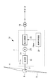
- FIG. 1 is a diagram illustrating an overall configuration of a wind power generation system according to the present embodiment.
- the wind power generation system 1 includes a plurality of wind turbines 10-1,..., 10-n (hereinafter, when all the wind turbines are indicated, a reference numeral “10” is attached to each wind turbine). In this case, reference numerals “10-1”, “10-n”, etc. are attached.)
- a central controller 2 that gives a first correction value to each wind turbine 10.
- all the windmills 10 are variable speed windmills capable of controlling the rotation speed according to the wind speed.
- the electric power output from each windmill 10 is supplied to the electric power grid
- the system frequency of the interconnection point A is measured by the frequency detection unit 25 (see FIG. 5) and is output to the central controller 2.
- the central control device 2 is a control device that controls the output at the interconnection point A.
- a request notified from a power management room (for example, a power company) that manages the power of the power system 3 An active power command is set for each wind turbine to match the output at the interconnection point A with the frequency and the required power value.
- the active power command for each wind turbine set by the central controller 2 is transmitted to the wind turbine control device 20 included in each wind turbine 10-1,..., 10-n, and output control based on this active power command is performed for each wind turbine. Done in
- FIG. 2 is an external view of the windmill 10, and FIG. 3 is a schematic diagram illustrating an electrical configuration of the windmill 10.
- the wind turbine 10 is provided in the nacelle 7 so as to be rotatable around a substantially horizontal axis line, a tower 6 standing on the foundation 5, a nacelle 7 installed on the upper end of the tower 6, and the like. And a rotor head 8.
- a plurality of blades 9 are radially attached to the rotor head 8 around its rotational axis.
- the blade 9 is connected so as to be rotatable with respect to the rotor head 8 according to operating conditions, and the pitch angle can be changed.
- a speed increaser 22 and a generator 23 are mechanically connected to the rotating shaft 21 of the rotor head 8.
- the generator 23 may be a synchronous generator or an induction generator. It is also possible to adopt a configuration in which the speed increaser 23 is not provided.
- the rotor head 8 is rotated around the rotation axis by the force of the wind hitting the blade 9 from the rotation axis direction of the rotor head 8, and the rotation force is increased by the speed increaser 22 and transmitted to the generator 23. Converted to electric power.
- the electric power generated by the generator 23 is converted into electric power corresponding to the electric power system 3 by the electric power converter 24 and supplied to the electric power system 1 through the transformer 19.
- the power conversion unit 24 is controlled by the windmill control device 20.
- the windmill control device 20 has a function of controlling the output of the generator 23 by controlling the power converter 24, a function of controlling the pitch angle of the blade 9, and the like.
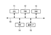
- the central control device 2 and the windmill control device 20 include a computer.
- a CPU 11 and a ROM (Read Only Memory) 12 for storing a program executed by the CPU 11,
- a RAM (Random Access Memory) 13 functioning as a work area when executing each program
- a hard disk drive (HDD) 14 as a mass storage device
- a communication interface 15 for connecting to a communication network are provided.
- These units are connected via a bus 18.
- the central control device 2 may include an access unit to which an external storage device is attached, an input unit including a keyboard and a mouse, a display unit including a liquid crystal display device that displays data, and the like.
- the storage medium for storing the program executed by the CPU 11 is not limited to the ROM 12.
- other auxiliary storage devices such as a magnetic disk, a magneto-optical disk, and a semiconductor memory may be used.
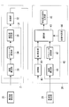
- FIG. 5 is a functional block diagram mainly showing functions related to frequency control that operates when, for example, system disturbance (frequency fluctuation) occurs, among the functions of the central control device 2 and the windmill control device 20.
- Central controller 2 generates first command information for suppressing frequency fluctuations at interconnection point A for each windmill, and generates the generated first command information for each windmill 10-1,. It transmits to the control apparatus 20.
- the central controller 2 includes a first processing unit 31 and a transmission unit 32 as shown in FIG.
- the first processing unit 31 includes a deviation calculating unit 33, a parameter converting unit 34, and a correction value setting unit 35.
- the deviation calculation unit 33 calculates a system frequency deviation ⁇ f grid that is a deviation between the system frequency detected by the frequency detection unit 25 and the rated frequency notified from the power management room. That is, the system frequency deviation ⁇ f grid is expressed by the following equation (1).
- f ref is a rated frequency and f grid is a system frequency.
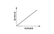
- the parameter conversion unit 34 has conversion information in which the relationship between the frequency deviation ⁇ f and the power correction value ⁇ P is set, and corresponds to the system frequency deviation ⁇ f grid calculated by the deviation calculation unit 33 using this conversion information.
- the grid power correction value ⁇ P grid to be acquired is acquired.
- Fig. 6 shows an example of conversion information.
- the horizontal axis indicates the frequency deviation ⁇ f
- the vertical axis indicates the power correction value ⁇ P.
- the conversion characteristics shown in FIG. 6 can be arbitrarily set according to the design of the wind turbine, and here, the slope is defined as a positive linear function.
- the grid power correction value ⁇ P grid acquired by the parameter conversion unit 34 is output to the correction value setting unit 35.
- the correction value setting unit 35 divides the grid power correction value ⁇ P grid by the number n of wind turbines in operation to equally distribute the grid power correction value ⁇ P grid to each wind turbine, and the first power corresponding to each wind turbine.
- Correction values ⁇ P id — n ,..., ⁇ P id — n are set.
- a weighting coefficient is set in advance for each wind turbine 10-1,..., 10-n, and the distribution of the grid power correction value ⁇ P grid to each wind turbine during operation is determined using this weighting coefficient. It is good to do.
- the first power correction values ⁇ P id — 1,..., ⁇ P id — n of the wind turbines set in this way are transmitted to the wind turbine controller 20 of each wind turbine as the first command information.
- Each windmill control device 20 includes a reception unit 40, a first setting unit 41, a second processing unit 42, a selection unit 43, a state determination unit 44, and an active power command generation unit 45. Since the configuration of the windmill control device 20 included in each of the windmills 10-1,..., 10-n is the same, the configuration of the windmill control device 20 of the windmill 10-1 is a representative example below for convenience of explanation. Will be described.
- the receiving unit 40 receives the first power correction value ⁇ P id — 1 transmitted from the central control device 2 and outputs it to the first setting unit 41.
- the first setting unit 41 sets the first power correction value ⁇ P id — 1 received by the receiving unit 40.
- the first power correction value ⁇ P id — 1 set by the first setting unit 41 is a power correction value for suppressing fluctuations in the system frequency.
- the second processing unit 42 sets second command information for generating an output command for suppressing the frequency fluctuation of the output of the corresponding wind turbine 10-1.
- the second processing unit 42 includes a deviation calculating unit 46 and a parameter converting unit 47.
- the deviation calculation unit 46 receives the output frequency of the windmill 10-1 detected by the frequency detection unit 26 (hereinafter referred to as “windmill frequency”).
- the deviation calculating unit 46 calculates a wind turbine frequency deviation ⁇ f wd_1 between the input wind turbine frequency and the rated frequency. That is, the wind turbine frequency deviation ⁇ f wd — 1 is expressed by the following equation (2).
- f ref is the rated frequency
- f wd_1 is the wind turbine frequency of the wind turbine 10-1.
- the parameter conversion unit 47 has, for example, the conversion information shown in FIG. 6 and uses the conversion information to obtain the wind turbine power correction value ⁇ P wd_1 corresponding to the wind turbine frequency deviation ⁇ f wd_1 calculated by the deviation calculation unit 46. It is acquired and set as a second power correction value (second command information).
- the selection unit 43 receives the first power correction value set by the first setting unit 41 and the second power correction value set by the second processing unit 42. When the system disturbance occurs, the selection unit 43 selects the second power correction value at the initial stage of the system disturbance, selects the first power correction value at the later stage of the system disturbance, and generates an active power command. To the unit 45. The occurrence of the system disturbance, the initial stage of the system disturbance, and the later stage of the system disturbance are determined by an input signal from the state determination unit 44.
- the state determination unit 44 detects the occurrence of system disturbance when the frequency fluctuation at the interconnection point A exceeds a predetermined first threshold value, and outputs a High signal to the selection unit 43. In addition, after the occurrence of the disturbance, when the state in which the fluctuation range of the system frequency is less than the second threshold set to a value equal to or less than the first threshold is maintained for a predetermined period or longer, the transition from the initial stage to the later stage is performed. Determination is made and the output signal is switched from the high signal to the low signal.
- the selection unit 43 selects the second power correction value ⁇ P wd_1 during the period in which the High signal is input from the state determination unit 44. In addition, the selection unit 43 selects the first power correction value ⁇ P id_1 during the period when the Low signal is input from the state determination unit 44, and outputs the first power correction value ⁇ P id_1 to the active power command generation unit 45.
- the active power command generation unit 45 has a reference active power command as a reference, and adds the first power correction value or the second power correction value input from the selection unit 43 to the reference active power command.
- an active power command is generated.
- a control signal Pdem for controlling the power conversion unit 24 is generated based on the active power command, and is output to the power conversion unit 24.
- the reference active power command may be a fixed value, or a predetermined calculation is performed using the current output of the generator 23, the rotational speed of the rotor head 8, the pitch angle of the blade 9, and the wind speed. May be a value that is sequentially calculated by.
- the central control device 2 sets the first power correction value such that the system frequency becomes the rated frequency at a predetermined time interval, and the first power correction value is the wind turbine of each wind turbine. It is transmitted to the control device 20.
- the reception unit 40 receives the first power correction value from the central control device 2, and the first setting unit 41 sets the first power correction value. Further, the second processing unit 42 sets a second power correction value with the output frequency of the corresponding windmill as the rated frequency.
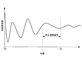
- the state determination unit 44 outputs a High signal when it is detected that a system disturbance has occurred at time T ⁇ b> 0, and then, when time passes, at time T ⁇ b> 1 in FIG. 7.
- the state where the frequency fluctuation at the interconnection point A is less than the second threshold is maintained for a predetermined period, it is detected that the state has shifted to the later stage of the system disturbance, and the output signal is changed from the High signal to Low. Switch to signal.
- the second power correction value is selected in the initial stage from the occurrence of the system disturbance (period T0 to T1 in FIG. 7), and after the transition from the initial stage of the system disturbance to the later stage In (after time T1 in FIG. 7), the first power correction value is selected. Therefore, in the initial stage of system disturbance occurrence, an active power command using the second power correction value that suppresses fluctuations in the wind turbine frequency is generated by the active power command generator 45, and the output of the wind turbine is generated based on this active power command. Is controlled. Further, in the later stage of the system disturbance, the active power command using the first power correction value that suppresses the fluctuation of the system frequency is generated by the active power command generation unit 45, and the output of the windmill is generated based on the active power command. Be controlled.
- the wind turbine control device 20 and the method thereof and the wind power generation system 1 according to the present embodiment when a system disturbance occurs, the frequency fluctuations of individual outputs of the wind turbine in the initial stage of the system disturbance. Output control is performed in each wind turbine, and in the later stage of the system disturbance, output control is performed in each wind turbine to suppress the system frequency at the connection point A.
- the control that suppresses the output frequency for each wind turbine is more responsive than the control that suppresses the system frequency. Therefore, it is possible to effectively suppress the frequency fluctuation at the interconnection point A by selecting the control that suppresses the output frequency fluctuation for each wind turbine in the initial stage of the system disturbance.
- the state determination unit 44 may have these two conditions, and may determine that the system has shifted to the later stage of the system disturbance when one of the two conditions is satisfied.
- the occurrence of the system disturbance and the transition from the initial stage to the late stage are determined based on the system frequency, but instead, the output frequency of each windmill is used to generate the system disturbance and the initial stage.
- the transition from the stage to the later stage may be determined.
- the first command information and the second command information respectively set by the first setting unit and the second processing unit are the power correction values. Instead, the first power correction value is reflected.
- the second active power command in which the first active power command and the second power correction value are reflected may be set as the first command information and the second command information.
- an active power command generation unit 45 may be provided between the first setting unit 41 and the selection unit 43 and between the parameter conversion unit 47 and the selection unit 43. Further, in this case, the central control device 2 generates a first active power command that suppresses frequency fluctuations at the interconnection point A for each wind turbine, and the generated first active power command is sent to each wind turbine 10. It is good also as transmitting. In this case, the first active power command received from the central control device 2 is set by the first setting unit 41.
Abstract
Description
本発明は、系統擾乱が発生した場合に、発生初期の段階から周波数変動を抑制することのできる風車制御装置及びその方法並びに風力発電システムを提供することを目的とする。 In recent years, the power generation scale of wind power generation has increased, and when a system disturbance occurs, it is effective to suppress the disturbance from the beginning.
It is an object of the present invention to provide a windmill control device, a method thereof, and a wind power generation system capable of suppressing frequency fluctuations from the initial generation stage when a system disturbance occurs.
図1は、本実施形態に係る風力発電システムの全体構成を示す図である。図1に示されるように、風力発電システム1は、複数の風車10-1,・・・,10-n(以下、全ての風車を示すときは単に符号「10」を付し、各風車を示すときは符号「10-1」、「10-n」等を付す。)と、各風車10に対して第1補正値を与える中央制御装置2とを備えている。 DESCRIPTION OF EMBODIMENTS Hereinafter, a windmill control device and method and a wind power generation system according to an embodiment of the present invention will be described with reference to the drawings.
FIG. 1 is a diagram illustrating an overall configuration of a wind power generation system according to the present embodiment. As shown in FIG. 1, the wind power generation system 1 includes a plurality of wind turbines 10-1,..., 10-n (hereinafter, when all the wind turbines are indicated, a reference numeral “10” is attached to each wind turbine). In this case, reference numerals “10-1”, “10-n”, etc. are attached.) And a
連系点Aの系統周波数は、周波数検出部25(図5参照)によって計測され、中央制御装置2に出力される。 In this embodiment, all the
The system frequency of the interconnection point A is measured by the frequency detection unit 25 (see FIG. 5) and is output to the
図2に示すように、風車10は、基礎5上に立設されるタワー6と、タワー6の上端に設置されるナセル7と、略水平な軸線周りに回転可能にしてナセル7に設けられるロータヘッド8とを有している。 FIG. 2 is an external view of the
As shown in FIG. 2, the
中央制御装置2は、連系点Aにおける周波数変動を抑制するための第1指令情報を風車毎に生成し、生成した第1指令情報を各風車10-1、・・・10-nの風車制御装置20に送信する。 FIG. 5 is a functional block diagram mainly showing functions related to frequency control that operates when, for example, system disturbance (frequency fluctuation) occurs, among the functions of the
第1処理部31は、偏差算出部33と、パラメータ変換部34と、補正値設定部35とを備えている。 For example, the
The
このようにして設定された各風車の第1電力補正値ΔPid_1,・・・,ΔPid_nは、第1指令情報として各風車の風車制御装置20に送信される。 It should be noted that a weighting coefficient is set in advance for each wind turbine 10-1,..., 10-n, and the distribution of the grid power correction value ΔP grid to each wind turbine during operation is determined using this weighting coefficient. It is good to do.
The first power correction values ΔP id — 1,..., ΔP id — n of the wind turbines set in this way are transmitted to the
第2処理部42は、対応する風車10-1の出力の周波数変動を抑制する出力指令を生成するための第2指令情報を設定する。具体的には、第2処理部42は、偏差算出部46と、パラメータ変換部47とを備えている。 The receiving
The
2 中央制御装置
3 電力系統
10-1、10-n 風車
20 風車制御装置
25、26 周波数検出部
31 第1処理部
32 送信部
33 偏差算出部
34 パラメータ変換部
35 補正値設定部
40 受信部
41 第1設定部
42 第2処理部
43 選択部
44 状態判定部
45 有効電力指令生成部
46 偏差算出部
47 パラメータ変換部
A 連系点 DESCRIPTION OF SYMBOLS 1 Wind
Claims (7)
- 複数の風車の出力が共通の連系点を通じて電力系統に供給される風力発電システムに適用され、各前記風車に対応してそれぞれ設けられた風車制御装置であって、
前記連系点における周波数変動を抑制する出力指令を生成するための第1指令情報を設定する第1設定手段と、
対応する前記風車の出力の周波数変動を抑制する出力指令を生成するための第2指令情報を設定する第2処理手段と、
前記連系点における周波数変動が所定の第1閾値を超える系統擾乱が発生した場合に、該系統擾乱の初期段階に前記第2指令情報を選択し、当該系統擾乱の後期段階に前記第1指令情報を選択する選択手段と、
前記選択手段によって選択された指令情報を用いて出力指令を生成する指令生成手段と
を具備する風車制御装置。 Applied to a wind power generation system in which the output of a plurality of windmills is supplied to an electric power system through a common interconnection point, a windmill control device provided corresponding to each windmill,
First setting means for setting first command information for generating an output command for suppressing frequency fluctuation at the interconnection point;
Second processing means for setting second command information for generating an output command for suppressing frequency fluctuation of the output of the corresponding windmill;
When a system disturbance in which the frequency fluctuation at the interconnection point exceeds a predetermined first threshold occurs, the second command information is selected at an initial stage of the system disturbance, and the first command is output at a later stage of the system disturbance. A selection means for selecting information;
A windmill control device comprising command generation means for generating an output command using the command information selected by the selection means. - 前記第1処理手段は、周波数変動と第1指令情報との関係が予め設定されている変換情報を用いて、前記連系点における周波数変動に対応する第1指令情報を取得して設定する請求項1に記載の風車制御装置。 The first processing means acquires and sets the first command information corresponding to the frequency variation at the interconnection point using conversion information in which a relationship between the frequency variation and the first command information is set in advance. Item 2. The windmill control device according to Item 1.
- 前記第2処理手段は、周波数変動と第2指令情報との関係が予め設定されている変換情報を用いて、前記風車の出力の周波数変動に対応する第2指令情報を取得して設定する請求項1または請求項2に記載の風車制御装置。 The second processing means acquires and sets the second command information corresponding to the frequency variation of the output of the windmill using conversion information in which a relationship between the frequency variation and the second command information is set in advance. The windmill control device according to claim 1 or claim 2.
- 周波数変動が前記第1閾値以下の値に設定された第2閾値未満である状態が所定の期間維持された場合、または、該周波数の変動周期が所定の第3閾値を越えた場合に、前記初期段階から前記後期段階に移行したと判定する状態判定手段を備え、
前記選択手段は、前記状態判定手段の判定結果に基づいて選択を行う請求項1から請求項3のいずれかに記載の風車制御装置。 When the state in which the frequency variation is less than the second threshold set to a value equal to or less than the first threshold is maintained for a predetermined period, or when the frequency variation period exceeds a predetermined third threshold, Comprising a state determining means for determining from the initial stage to the latter stage,
The wind turbine control device according to any one of claims 1 to 3, wherein the selection unit performs selection based on a determination result of the state determination unit. - 前記第1設定手段は、前記連系点における出力を制御する中央制御手段から前記第1指令情報を受信し、受信した前記第1指令情報を設定する請求項1から請求項4のいずれかに記載の風車制御装置。 The said 1st setting means receives the said 1st command information from the central control means which controls the output in the said connection point, The said 1st command information is set in any one of Claims 1-4. The windmill control device described.
- 複数の風車の出力が共通の連系点を通じて電力系統に供給される風力発電システムに適用される各前記風車の制御方法であって、
前記連系点における周波数変動を抑制する出力指令を生成するための第1指令情報を設定する第1設定過程と、
対応する前記風車の出力の周波数変動を抑制する出力指令を生成するための第2指令情報を設定する第2処理過程と、
前記連系点における周波数変動が所定の第1閾値を超える系統擾乱が発生した場合に、該系統擾乱の初期段階に前記第2指令情報を選択し、当該系統擾乱の後期段階に前記第1指令情報を選択する選択過程と、
前記選択過程によって選択された指令情報を用いて出力指令を生成する指令生成過程と
を含む風車の制御方法。 A method for controlling each of the windmills applied to a wind power generation system in which outputs of a plurality of windmills are supplied to a power system through a common interconnection point,
A first setting step of setting first command information for generating an output command for suppressing frequency fluctuation at the interconnection point;
A second processing step of setting second command information for generating an output command for suppressing a frequency fluctuation of the output of the corresponding windmill;
When a system disturbance in which the frequency fluctuation at the interconnection point exceeds a predetermined first threshold occurs, the second command information is selected at an initial stage of the system disturbance, and the first command is output at a later stage of the system disturbance. A selection process for selecting information;
A wind turbine control method including a command generation process for generating an output command using the command information selected in the selection process. - 複数の風車を備え、各前記風車の出力が共通の連系点を通じて電力系統に供給される風力発電システムであって、
前記連系点における出力を制御する中央制御手段と、
各前記風車に対応してそれぞれ設けられ、対応する前記風車の出力を制御する複数の風車制御手段と
を備え、
前記中央制御手段は、
前記連系点における周波数変動を抑制する出力指令を生成するための第1指令情報を設定する第1処理手段と、
前記第1処理手段によって設定された各前記風車の第1指令情報をそれぞれの前記風車に送信する送信手段と
を備え、
各前記風車制御手段は、
前記中央制御手段から前記第1指令情報を受信する受信手段と、
受信した前記第1指令情報を設定する第1設定手段と、
対応する前記風車の出力の周波数変動を抑制する出力指令を生成するための第2指令情報を設定する第2処理手段と、
前記連系点における周波数変動が所定の第1閾値を超える系統擾乱が発生した場合に、該系統擾乱の初期段階に前記第2指令情報を選択し、当該系統擾乱の後期段階に前記第1指令情報を選択する選択手段と、
前記選択手段によって選択された指令情報を用いて出力指令を生成する指令生成手段と
を具備する風力発電システム。 A wind power generation system comprising a plurality of windmills, wherein the output of each windmill is supplied to the power system through a common interconnection point,
Central control means for controlling the output at the interconnection point;
A plurality of windmill control means provided for each of the windmills to control the output of the corresponding windmill,
The central control means includes
First processing means for setting first command information for generating an output command for suppressing frequency fluctuation at the interconnection point;
Transmission means for transmitting the first command information of each windmill set by the first processing means to each windmill,
Each of the windmill control means
Receiving means for receiving the first command information from the central control means;
First setting means for setting the received first command information;
Second processing means for setting second command information for generating an output command for suppressing frequency fluctuation of the output of the corresponding windmill;
When a system disturbance in which the frequency fluctuation at the interconnection point exceeds a predetermined first threshold occurs, the second command information is selected at an initial stage of the system disturbance, and the first command is output at a later stage of the system disturbance. A selection means for selecting information;
A wind power generation system comprising: command generation means for generating an output command using the command information selected by the selection means.
Priority Applications (6)
| Application Number | Priority Date | Filing Date | Title |
|---|---|---|---|
| JP2012556731A JP5325348B1 (en) | 2012-02-24 | 2012-02-24 | Windmill control device and method, and wind power generation system |
| CN201280001239.XA CN102971528B (en) | 2012-02-24 | 2012-02-24 | Windmill control apparatus and method thereof and wind-power generating system |
| EP12801792.8A EP2818699B1 (en) | 2012-02-24 | 2012-02-24 | Wind turbine control device and method, and wind power generation system |
| PCT/JP2012/054654 WO2013125044A1 (en) | 2012-02-24 | 2012-02-24 | Wind turbine control device and method, and wind power generation system |
| KR1020127033763A KR20130106287A (en) | 2012-02-24 | 2012-02-24 | Windmill control device and method and wind power generation system |
| US13/474,036 US8610299B2 (en) | 2012-02-24 | 2012-05-17 | Wind turbine control device and method for reducing fluctuation of grid frequency when grid disturbance occurs, and wind turbine generator system thereof |
Applications Claiming Priority (1)
| Application Number | Priority Date | Filing Date | Title |
|---|---|---|---|
| PCT/JP2012/054654 WO2013125044A1 (en) | 2012-02-24 | 2012-02-24 | Wind turbine control device and method, and wind power generation system |
Related Child Applications (1)
| Application Number | Title | Priority Date | Filing Date |
|---|---|---|---|
| US13/474,036 Continuation US8610299B2 (en) | 2012-02-24 | 2012-05-17 | Wind turbine control device and method for reducing fluctuation of grid frequency when grid disturbance occurs, and wind turbine generator system thereof |
Publications (1)
| Publication Number | Publication Date |
|---|---|
| WO2013125044A1 true WO2013125044A1 (en) | 2013-08-29 |
Family
ID=47800629
Family Applications (1)
| Application Number | Title | Priority Date | Filing Date |
|---|---|---|---|
| PCT/JP2012/054654 WO2013125044A1 (en) | 2012-02-24 | 2012-02-24 | Wind turbine control device and method, and wind power generation system |
Country Status (6)
| Country | Link |
|---|---|
| US (1) | US8610299B2 (en) |
| EP (1) | EP2818699B1 (en) |
| JP (1) | JP5325348B1 (en) |
| KR (1) | KR20130106287A (en) |
| CN (1) | CN102971528B (en) |
| WO (1) | WO2013125044A1 (en) |
Families Citing this family (5)
| Publication number | Priority date | Publication date | Assignee | Title |
|---|---|---|---|---|
| CN104285059B (en) | 2012-05-11 | 2017-03-01 | 维斯塔斯风力系统集团公司 | Wind power plant's FREQUENCY CONTROL |
| DE102013204600A1 (en) * | 2013-03-15 | 2014-09-18 | Senvion Se | Wind turbine with frequency measurement |
| DK178820B1 (en) | 2014-11-04 | 2017-02-27 | Kk Wind Solutions As | Monitoring unit for a power converter |
| WO2017101941A1 (en) * | 2015-12-17 | 2017-06-22 | Vestas Wind Systems A/S | Modulating wind power plant output using different frequency modulation components for damping grid oscillations |
| CN105811407B (en) * | 2016-04-18 | 2018-07-06 | 清华大学 | A kind of micro-capacitance sensor primary frequency modulation control method based on distributed Newton method |
Citations (6)
| Publication number | Priority date | Publication date | Assignee | Title |
|---|---|---|---|---|
| JP2001234845A (en) * | 2000-02-22 | 2001-08-31 | Okinawa Electric Power Co Ltd | Output control method in operating plural wind power generators |
| JP2008283747A (en) * | 2007-05-09 | 2008-11-20 | Hitachi Ltd | Wind power generation system and its control method |
| JP2009303355A (en) * | 2008-06-12 | 2009-12-24 | Hitachi Ltd | Wind-power generation apparatus and wind-power generation apparatus group |
| WO2011016278A1 (en) * | 2009-08-06 | 2011-02-10 | 三菱重工業株式会社 | Wind-power generation device, control method for wind-power generation device, wind-power generation system, and control method for wind-power generation system |
| WO2011158351A1 (en) * | 2010-06-16 | 2011-12-22 | 三菱重工業株式会社 | Wind power generator control device and control method |
| JP4848478B1 (en) * | 2011-04-14 | 2011-12-28 | 三菱重工業株式会社 | Output leveling method for wind power generation equipment and output leveling apparatus for wind power generation equipment |
Family Cites Families (6)
| Publication number | Priority date | Publication date | Assignee | Title |
|---|---|---|---|---|
| ES2338396B1 (en) * | 2007-12-27 | 2011-04-08 | GAMESA INNOVATION & TECHONOLOGY S.L. | WIND ENERGY INSTALLATION AND PROCEDURE FOR OPERATION. |
| US7679208B1 (en) * | 2008-09-18 | 2010-03-16 | Samsung Heavy Ind. Co., Ltd. | Apparatus and system for pitch angle control of wind turbine |
| CN101793227B (en) * | 2008-12-12 | 2013-11-06 | 维斯塔斯风力系统有限公司 | A method for controlling the operation of a wind turbine and a wind turbine |
| DE102009017939A1 (en) * | 2009-04-17 | 2010-11-11 | Nordex Energy Gmbh | Wind farm with several wind turbines as well as procedures for controlling the feed-in from a wind farm |
| DE102009030725A1 (en) * | 2009-06-26 | 2010-12-30 | Repower Systems Ag | Wind farm and method for controlling a wind farm |
| JP5433682B2 (en) * | 2010-10-29 | 2014-03-05 | 三菱重工業株式会社 | Wind turbine generator control device, wind farm, and wind turbine generator control method |
-
2012
- 2012-02-24 EP EP12801792.8A patent/EP2818699B1/en active Active
- 2012-02-24 JP JP2012556731A patent/JP5325348B1/en active Active
- 2012-02-24 KR KR1020127033763A patent/KR20130106287A/en active IP Right Grant
- 2012-02-24 WO PCT/JP2012/054654 patent/WO2013125044A1/en active Application Filing
- 2012-02-24 CN CN201280001239.XA patent/CN102971528B/en active Active
- 2012-05-17 US US13/474,036 patent/US8610299B2/en active Active
Patent Citations (6)
| Publication number | Priority date | Publication date | Assignee | Title |
|---|---|---|---|---|
| JP2001234845A (en) * | 2000-02-22 | 2001-08-31 | Okinawa Electric Power Co Ltd | Output control method in operating plural wind power generators |
| JP2008283747A (en) * | 2007-05-09 | 2008-11-20 | Hitachi Ltd | Wind power generation system and its control method |
| JP2009303355A (en) * | 2008-06-12 | 2009-12-24 | Hitachi Ltd | Wind-power generation apparatus and wind-power generation apparatus group |
| WO2011016278A1 (en) * | 2009-08-06 | 2011-02-10 | 三菱重工業株式会社 | Wind-power generation device, control method for wind-power generation device, wind-power generation system, and control method for wind-power generation system |
| WO2011158351A1 (en) * | 2010-06-16 | 2011-12-22 | 三菱重工業株式会社 | Wind power generator control device and control method |
| JP4848478B1 (en) * | 2011-04-14 | 2011-12-28 | 三菱重工業株式会社 | Output leveling method for wind power generation equipment and output leveling apparatus for wind power generation equipment |
Non-Patent Citations (1)
| Title |
|---|
| See also references of EP2818699A4 * |
Also Published As
| Publication number | Publication date |
|---|---|
| JP5325348B1 (en) | 2013-10-23 |
| US20130221669A1 (en) | 2013-08-29 |
| US8610299B2 (en) | 2013-12-17 |
| KR20130106287A (en) | 2013-09-27 |
| CN102971528B (en) | 2014-06-11 |
| EP2818699B1 (en) | 2016-07-27 |
| JPWO2013125044A1 (en) | 2015-07-30 |
| EP2818699A4 (en) | 2015-10-14 |
| EP2818699A1 (en) | 2014-12-31 |
| CN102971528A (en) | 2013-03-13 |
Similar Documents
| Publication | Publication Date | Title |
|---|---|---|
| JP5237454B2 (en) | Wind power generator and control method thereof | |
| JP5167365B2 (en) | Monitoring and control apparatus and method, and wind farm having the same | |
| US7987067B2 (en) | Method and apparatus for optimizing wind turbine operation | |
| US20120143537A1 (en) | Method of calculating an electrical output of a wind power plant | |
| JP5485368B2 (en) | Wind power generation system and control method thereof | |
| KR20120025499A (en) | Wind-power generation device, control method for wind-power generation device, wind-power generation system, and control method for wind-power generation system | |
| JP5325348B1 (en) | Windmill control device and method, and wind power generation system | |
| JP5272113B1 (en) | Wind power generation system, control device therefor, and control method therefor | |
| EP2955370B1 (en) | Method and system for managing loads on a wind turbine | |
| CN111936740B (en) | Reactive current margin regulator for power system | |
| JP5245017B1 (en) | Wind power generation system and control method thereof | |
| JP5272112B1 (en) | Wind power generation system, control device therefor, and control method therefor | |
| JP2013181440A (en) | Wind power generation system, control device and control method thereof |
Legal Events
| Date | Code | Title | Description |
|---|---|---|---|
| WWE | Wipo information: entry into national phase |
Ref document number: 201280001239.X Country of ref document: CN |
|
| ENP | Entry into the national phase |
Ref document number: 2012556731 Country of ref document: JP Kind code of ref document: A |
|
| ENP | Entry into the national phase |
Ref document number: 20127033763 Country of ref document: KR Kind code of ref document: A |
|
| REEP | Request for entry into the european phase |
Ref document number: 2012801792 Country of ref document: EP |
|
| WWE | Wipo information: entry into national phase |
Ref document number: 2012801792 Country of ref document: EP |
|
| 121 | Ep: the epo has been informed by wipo that ep was designated in this application |
Ref document number: 12801792 Country of ref document: EP Kind code of ref document: A1 |
|
| NENP | Non-entry into the national phase |
Ref country code: DE |