JP3918837B2 - Wind power generator - Google Patents
Wind power generator Download PDFInfo
- Publication number
- JP3918837B2 JP3918837B2 JP2004230058A JP2004230058A JP3918837B2 JP 3918837 B2 JP3918837 B2 JP 3918837B2 JP 2004230058 A JP2004230058 A JP 2004230058A JP 2004230058 A JP2004230058 A JP 2004230058A JP 3918837 B2 JP3918837 B2 JP 3918837B2
- Authority
- JP
- Japan
- Prior art keywords
- power
- generator
- command
- output
- speed
- Prior art date
- Legal status (The legal status is an assumption and is not a legal conclusion. Google has not performed a legal analysis and makes no representation as to the accuracy of the status listed.)
- Active
Links
- 238000001514 detection method Methods 0.000 claims description 58
- 230000005284 excitation Effects 0.000 claims description 33
- 230000001360 synchronised effect Effects 0.000 claims description 33
- 238000004804 winding Methods 0.000 claims 4
- 238000010586 diagram Methods 0.000 description 8
- 238000010248 power generation Methods 0.000 description 8
- 230000010354 integration Effects 0.000 description 4
- 239000003990 capacitor Substances 0.000 description 3
- 230000007423 decrease Effects 0.000 description 3
- 230000003247 decreasing effect Effects 0.000 description 2
- 239000004065 semiconductor Substances 0.000 description 2
- 230000001052 transient effect Effects 0.000 description 1
Images


Classifications
-
- H—ELECTRICITY
- H02—GENERATION; CONVERSION OR DISTRIBUTION OF ELECTRIC POWER
- H02P—CONTROL OR REGULATION OF ELECTRIC MOTORS, ELECTRIC GENERATORS OR DYNAMO-ELECTRIC CONVERTERS; CONTROLLING TRANSFORMERS, REACTORS OR CHOKE COILS
- H02P9/00—Arrangements for controlling electric generators for the purpose of obtaining a desired output
- H02P9/006—Means for protecting the generator by using control
-
- F—MECHANICAL ENGINEERING; LIGHTING; HEATING; WEAPONS; BLASTING
- F03—MACHINES OR ENGINES FOR LIQUIDS; WIND, SPRING, OR WEIGHT MOTORS; PRODUCING MECHANICAL POWER OR A REACTIVE PROPULSIVE THRUST, NOT OTHERWISE PROVIDED FOR
- F03D—WIND MOTORS
- F03D7/00—Controlling wind motors
- F03D7/02—Controlling wind motors the wind motors having rotation axis substantially parallel to the air flow entering the rotor
- F03D7/0272—Controlling wind motors the wind motors having rotation axis substantially parallel to the air flow entering the rotor by measures acting on the electrical generator
-
- F—MECHANICAL ENGINEERING; LIGHTING; HEATING; WEAPONS; BLASTING
- F03—MACHINES OR ENGINES FOR LIQUIDS; WIND, SPRING, OR WEIGHT MOTORS; PRODUCING MECHANICAL POWER OR A REACTIVE PROPULSIVE THRUST, NOT OTHERWISE PROVIDED FOR
- F03D—WIND MOTORS
- F03D7/00—Controlling wind motors
- F03D7/02—Controlling wind motors the wind motors having rotation axis substantially parallel to the air flow entering the rotor
- F03D7/028—Controlling wind motors the wind motors having rotation axis substantially parallel to the air flow entering the rotor controlling wind motor output power
-
- F—MECHANICAL ENGINEERING; LIGHTING; HEATING; WEAPONS; BLASTING
- F03—MACHINES OR ENGINES FOR LIQUIDS; WIND, SPRING, OR WEIGHT MOTORS; PRODUCING MECHANICAL POWER OR A REACTIVE PROPULSIVE THRUST, NOT OTHERWISE PROVIDED FOR
- F03D—WIND MOTORS
- F03D7/00—Controlling wind motors
- F03D7/02—Controlling wind motors the wind motors having rotation axis substantially parallel to the air flow entering the rotor
- F03D7/04—Automatic control; Regulation
- F03D7/042—Automatic control; Regulation by means of an electrical or electronic controller
-
- F—MECHANICAL ENGINEERING; LIGHTING; HEATING; WEAPONS; BLASTING
- F03—MACHINES OR ENGINES FOR LIQUIDS; WIND, SPRING, OR WEIGHT MOTORS; PRODUCING MECHANICAL POWER OR A REACTIVE PROPULSIVE THRUST, NOT OTHERWISE PROVIDED FOR
- F03D—WIND MOTORS
- F03D9/00—Adaptations of wind motors for special use; Combinations of wind motors with apparatus driven thereby; Wind motors specially adapted for installation in particular locations
- F03D9/20—Wind motors characterised by the driven apparatus
- F03D9/25—Wind motors characterised by the driven apparatus the apparatus being an electrical generator
- F03D9/255—Wind motors characterised by the driven apparatus the apparatus being an electrical generator connected to electrical distribution networks; Arrangements therefor
-
- H—ELECTRICITY
- H02—GENERATION; CONVERSION OR DISTRIBUTION OF ELECTRIC POWER
- H02J—CIRCUIT ARRANGEMENTS OR SYSTEMS FOR SUPPLYING OR DISTRIBUTING ELECTRIC POWER; SYSTEMS FOR STORING ELECTRIC ENERGY
- H02J3/00—Circuit arrangements for ac mains or ac distribution networks
- H02J3/38—Arrangements for parallely feeding a single network by two or more generators, converters or transformers
- H02J3/381—Dispersed generators
-
- H—ELECTRICITY
- H02—GENERATION; CONVERSION OR DISTRIBUTION OF ELECTRIC POWER
- H02J—CIRCUIT ARRANGEMENTS OR SYSTEMS FOR SUPPLYING OR DISTRIBUTING ELECTRIC POWER; SYSTEMS FOR STORING ELECTRIC ENERGY
- H02J3/00—Circuit arrangements for ac mains or ac distribution networks
- H02J3/38—Arrangements for parallely feeding a single network by two or more generators, converters or transformers
- H02J3/46—Controlling of the sharing of output between the generators, converters, or transformers
- H02J3/48—Controlling the sharing of the in-phase component
-
- F—MECHANICAL ENGINEERING; LIGHTING; HEATING; WEAPONS; BLASTING
- F05—INDEXING SCHEMES RELATING TO ENGINES OR PUMPS IN VARIOUS SUBCLASSES OF CLASSES F01-F04
- F05B—INDEXING SCHEME RELATING TO WIND, SPRING, WEIGHT, INERTIA OR LIKE MOTORS, TO MACHINES OR ENGINES FOR LIQUIDS COVERED BY SUBCLASSES F03B, F03D AND F03G
- F05B2270/00—Control
- F05B2270/10—Purpose of the control system
- F05B2270/1016—Purpose of the control system in variable speed operation
-
- F—MECHANICAL ENGINEERING; LIGHTING; HEATING; WEAPONS; BLASTING
- F05—INDEXING SCHEMES RELATING TO ENGINES OR PUMPS IN VARIOUS SUBCLASSES OF CLASSES F01-F04
- F05B—INDEXING SCHEME RELATING TO WIND, SPRING, WEIGHT, INERTIA OR LIKE MOTORS, TO MACHINES OR ENGINES FOR LIQUIDS COVERED BY SUBCLASSES F03B, F03D AND F03G
- F05B2270/00—Control
- F05B2270/10—Purpose of the control system
- F05B2270/103—Purpose of the control system to affect the output of the engine
- F05B2270/1033—Power (if explicitly mentioned)
-
- F—MECHANICAL ENGINEERING; LIGHTING; HEATING; WEAPONS; BLASTING
- F05—INDEXING SCHEMES RELATING TO ENGINES OR PUMPS IN VARIOUS SUBCLASSES OF CLASSES F01-F04
- F05B—INDEXING SCHEME RELATING TO WIND, SPRING, WEIGHT, INERTIA OR LIKE MOTORS, TO MACHINES OR ENGINES FOR LIQUIDS COVERED BY SUBCLASSES F03B, F03D AND F03G
- F05B2270/00—Control
- F05B2270/30—Control parameters, e.g. input parameters
- F05B2270/327—Rotor or generator speeds
-
- G—PHYSICS
- G09—EDUCATION; CRYPTOGRAPHY; DISPLAY; ADVERTISING; SEALS
- G09G—ARRANGEMENTS OR CIRCUITS FOR CONTROL OF INDICATING DEVICES USING STATIC MEANS TO PRESENT VARIABLE INFORMATION
- G09G2320/00—Control of display operating conditions
- G09G2320/06—Adjustment of display parameters
- G09G2320/0626—Adjustment of display parameters for control of overall brightness
- G09G2320/064—Adjustment of display parameters for control of overall brightness by time modulation of the brightness of the illumination source
-
- H—ELECTRICITY
- H02—GENERATION; CONVERSION OR DISTRIBUTION OF ELECTRIC POWER
- H02J—CIRCUIT ARRANGEMENTS OR SYSTEMS FOR SUPPLYING OR DISTRIBUTING ELECTRIC POWER; SYSTEMS FOR STORING ELECTRIC ENERGY
- H02J2300/00—Systems for supplying or distributing electric power characterised by decentralized, dispersed, or local generation
- H02J2300/20—The dispersed energy generation being of renewable origin
- H02J2300/28—The renewable source being wind energy
-
- H—ELECTRICITY
- H02—GENERATION; CONVERSION OR DISTRIBUTION OF ELECTRIC POWER
- H02P—CONTROL OR REGULATION OF ELECTRIC MOTORS, ELECTRIC GENERATORS OR DYNAMO-ELECTRIC CONVERTERS; CONTROLLING TRANSFORMERS, REACTORS OR CHOKE COILS
- H02P2101/00—Special adaptation of control arrangements for generators
- H02P2101/15—Special adaptation of control arrangements for generators for wind-driven turbines
-
- Y—GENERAL TAGGING OF NEW TECHNOLOGICAL DEVELOPMENTS; GENERAL TAGGING OF CROSS-SECTIONAL TECHNOLOGIES SPANNING OVER SEVERAL SECTIONS OF THE IPC; TECHNICAL SUBJECTS COVERED BY FORMER USPC CROSS-REFERENCE ART COLLECTIONS [XRACs] AND DIGESTS
- Y02—TECHNOLOGIES OR APPLICATIONS FOR MITIGATION OR ADAPTATION AGAINST CLIMATE CHANGE
- Y02E—REDUCTION OF GREENHOUSE GAS [GHG] EMISSIONS, RELATED TO ENERGY GENERATION, TRANSMISSION OR DISTRIBUTION
- Y02E10/00—Energy generation through renewable energy sources
- Y02E10/70—Wind energy
- Y02E10/72—Wind turbines with rotation axis in wind direction
-
- Y—GENERAL TAGGING OF NEW TECHNOLOGICAL DEVELOPMENTS; GENERAL TAGGING OF CROSS-SECTIONAL TECHNOLOGIES SPANNING OVER SEVERAL SECTIONS OF THE IPC; TECHNICAL SUBJECTS COVERED BY FORMER USPC CROSS-REFERENCE ART COLLECTIONS [XRACs] AND DIGESTS
- Y02—TECHNOLOGIES OR APPLICATIONS FOR MITIGATION OR ADAPTATION AGAINST CLIMATE CHANGE
- Y02E—REDUCTION OF GREENHOUSE GAS [GHG] EMISSIONS, RELATED TO ENERGY GENERATION, TRANSMISSION OR DISTRIBUTION
- Y02E10/00—Energy generation through renewable energy sources
- Y02E10/70—Wind energy
- Y02E10/76—Power conversion electric or electronic aspects
Description
本発明は風力発電装置に関し、特に風車の回転速度を維持することで風車の連続運転を可能とする風力発電装置に関する。 The present invention relates to a wind turbine generator, and more particularly to a wind turbine generator that enables continuous wind turbine operation by maintaining the rotational speed of the wind turbine.
従来技術の風力発電システムを説明する。風車は発電機に接続され、風のパワーによって風車が回転し、風車が発電機を駆動することで発電機が発電する。発電機として同期発電機を用いる場合は、発電機の固定子は順変換器に接続されて、発電機の出力する交流電力が変換器により直流電力に変換されて、さらに逆変換器により商用周波数の交流電力に変換されて電力系統に供給される。変換器は外部から与えられる電力指令に従って発電機の出力を制御する。このような構成の風力発電システムの一例が、特許文献1に記載されている。 A conventional wind power generation system will be described. The windmill is connected to a generator, the windmill is rotated by wind power, and the windmill drives the generator to generate power. When a synchronous generator is used as the generator, the generator stator is connected to the forward converter, the AC power output from the generator is converted to DC power by the converter, and further the commercial frequency by the inverter. Is converted to AC power and supplied to the power system. The converter controls the output of the generator according to a power command given from the outside. An example of such a wind power generation system is described in Patent Document 1.
風力発電システムは風速の変動に大きく影響されて風車の回転速度が変動する。風車の回転速度が運転範囲を逸脱する場合には通常は風車を保護するために運転を停止する。そこで、従来は風速が変動する場合には風速に応じて風車のブレードのピッチ角を制御したり、変換器へ与える電力指令を風速に応じて調整し、風車の回転速度変動を抑制している。 The wind power generation system is greatly influenced by fluctuations in wind speed, and the rotational speed of the windmill fluctuates. When the rotational speed of the windmill deviates from the operating range, the operation is usually stopped to protect the windmill. Therefore, conventionally, when the wind speed fluctuates, the pitch angle of the blade of the windmill is controlled according to the wind speed, or the power command given to the converter is adjusted according to the wind speed to suppress fluctuations in the rotational speed of the windmill. .
しかし、風速に応じて風車のブレードを駆動してピッチ角を制御することは機械的動作を含むために応答性が高くなく、風速に応じて変換器へ与える電力指令を調整する際も、通常は平均風速に基づいたパワーカーブにより決定するために、過渡的な風速の変化に追従することが困難である。このため、風速が急変する時に風車の回転速度が運転範囲を逸脱して風車が停止する場合があり、このような場合には再度風車を起動させる必要がある。 However, controlling the pitch angle by driving the blades of the wind turbine according to the wind speed is not highly responsive because it includes a mechanical operation, and even when adjusting the power command given to the converter according to the wind speed Is determined by a power curve based on the average wind speed, so it is difficult to follow a transient change in wind speed. For this reason, when the wind speed changes suddenly, the rotational speed of the windmill may deviate from the operating range and the windmill may stop. In such a case, it is necessary to start the windmill again.
しかしながら、風車発電量を増加させるためには、風速が急変する場合にもできるだけ風車が連続運転できることが望ましい。風車発電量が増加すれば風車発電コストを低減できるため、風車を連続運転して風車利用率を向上することが重要である。また、風車を連続運転できれば風車を系統に連系する開閉器等の動作回数が低減し、それらの機器の長寿命化も図れる。 However, in order to increase the wind turbine power generation amount, it is desirable that the wind turbine can be continuously operated as much as possible even when the wind speed changes suddenly. Since the wind turbine power generation cost can be reduced if the wind turbine power generation amount increases, it is important to continuously operate the wind turbine to improve the wind turbine utilization rate. In addition, if the windmill can be operated continuously, the number of operations of a switch or the like connecting the windmill to the system can be reduced, and the life of these devices can be extended.
本発明の目的は、風速が急変する場合にも、風車の回転速度を運転範囲内に制御し、風車の連続運転を行うことで風車利用率の向上を図る風力発電装置を提供することにある。 An object of the present invention is to provide a wind turbine generator that improves the wind turbine utilization rate by controlling the rotational speed of the wind turbine within the operation range and continuously operating the wind turbine even when the wind speed changes suddenly. .
本発明の風力発電装置は、風車の軸に接続した発電機と前記発電機に接続する変換器を備え、前記風車の回転速度が所定の領域にある場合には前記発電機から出力される電力を前記風車から前記変換器へ与えられる発電機出力に関する指令に追従するように制御し、前記風車の回転速度が所定の領域から外れる場合には前記発電機から出力される電力を前記風車から前記変換器へ与えられる発電機出力に関する指令に追従せずに制御する。 A wind turbine generator according to the present invention includes a generator connected to a shaft of a windmill and a converter connected to the generator, and the power output from the generator when the rotational speed of the windmill is in a predetermined region. Is controlled to follow a command relating to the generator output given from the windmill to the converter, and when the rotational speed of the windmill is out of a predetermined region, the power output from the generator is Control without following the command related to the generator output given to the converter.
本発明の風力発電装置は、前記風車の回転速度が所定の領域にある場合には前記発電機から出力される電力を前記風車から前記変換器へ与えられる発電機トルクに関する指令に前記風車の回転速度を乗じた値に追従するように制御し、前記風車の回転速度が所定の領域から外れる場合には前記発電機から出力される電力を前記風車から前記変換器へ与えられる発電機トルクに関する指令に前記風車の回転速度を乗じた値に追従せずに制御する。 In the wind turbine generator according to the present invention, when the rotational speed of the windmill is in a predetermined region, the rotation of the windmill is in response to a command relating to the generator torque that is supplied from the windmill to the converter. A command relating to the generator torque that is controlled to follow the value multiplied by the speed, and that outputs the electric power output from the generator to the converter when the rotational speed of the wind turbine deviates from a predetermined range. The control is performed without following a value obtained by multiplying the rotation speed of the wind turbine by the above.
本発明によれば、風車の回転速度が設定範囲内にある場合には外部から与えられる指令に従って風車の出力を制御することができ、風車の回転速度が設定範囲を逸脱した場合には風車の回転速度を設定範囲内で抑えるように速度制御を行うので、風速が変動した場合に風車の停止を避けることができる。 According to the present invention, when the rotational speed of the windmill is within the set range, it is possible to control the output of the windmill according to a command given from the outside, and when the rotational speed of the windmill deviates from the set range, Since the speed control is performed so as to suppress the rotation speed within the set range, it is possible to avoid stopping the windmill when the wind speed fluctuates.
以下、本発明の詳細を図面を用いて説明する。 Hereinafter, details of the present invention will be described with reference to the drawings.
図1は本実施例の全体構成を示す。図1に示す同期発電機2の回転子は風車1の軸に接続し、風車1が風速に応じた風のパワーで回転すると、同期発電機2は風車1の回転速度に応じた可変周波数の交流電力を発生する。同期発電機2の固定子には変換器3が接続し、同期発電機2が発生する可変周波数の交流電力を変換器3により直流電力に変換する。変換器3は直流コンデンサ4を介し、変換器5に直流で接続しており、変換器5は変換器3から送られる直流電力を固定周波数の交流電力に変換する。変換器5は系統連系用変圧器6を介して電力系統に接続しており、固定周波数の交流電力を電力系統に供給する。
FIG. 1 shows the overall configuration of this embodiment. The rotor of the
同期発電機2と変換器3との間には電圧検出センサ7と電流検出センサ8が設置されており、電圧検出センサ7は同期発電機2の固定子の端子電圧を、電流検出センサ8は同期発電機2の固定子に流れる電流をそれぞれ検出する。検出した電圧値を3相/2相変換器9によってd軸成分V_dとq軸成分V_qとに変換し、検出した電流値を3相/2相変換器10によってd軸成分I_dとq軸成分I_qに変換する。なお、本実施例では、d軸成分は無効成分を、q軸成分は有効成分を表す。
A voltage detection sensor 7 and a
速度検出器11は3相/2相変換器9、10が出力するV_d、V_q、I_d、I_qの信号に基づいて、風車1の回転速度ω及び同期発電機2の回転子位相θを検出する。
The speed detector 11 detects the rotational speed ω of the windmill 1 and the rotor phase θ of the
電力検出器12は3相/2相変換器9、10が出力するV_d、V_q、I_d、I_qの信号に基づいて、同期発電機2の出力する有効電力P及び無効電力Qを検出する。
The
速度制御器13は、予め定められたパワーカーブと風車で計測された風速とから求めた出力に応じて外部から同期発電機2へ与えられる有効電力指令P_c を、速度検出器11の検出する回転速度検出値ωに応じて修正し、同期発電機2へ修正した有効電力指令P_refを出力する。
The
無効電力指令演算器14は速度制御器13が出力する同期発電機2への有効電力指令P_refから同期発電機2への無効電力指令Q_ref を出力する。無効電力指令Q_refは同期発電機2の力率を調整するために設定される。
The reactive
有効電力制御器15の入力は速度制御器13の出力する有効電力指令P_ref と電力検出器12が出力する有効電力検出値Pとであり、有効電力制御器15の出力は変換器3への電流指令のq軸成分I_q_refとなる。有効電力制御器15は例えば比例積分制御系により構成され、有効電力指令P_refと有効電力検出値Pの偏差が零になるように変換器3への電流指令I_q_refを決定する。
The input of the
無効電力制御器16の入力は無効電力指令演算器14の出力する無効電力指令Q_refと電力検出器12の検出する無効電力検出値Qであり、出力は変換器3への電流指令のd軸成分I_d_refとなる。無効電力制御器16は例えば比例積分制御系により構成され、無効電力指令Q_ref と無効電力検出値Qの偏差が零になるように変換器3への電流指令I_d_refを決定する。
The input of the
q軸電流制御器17の入力は3相/2相変換器10が出力する電流検出値のq軸成分I_qと変換器3への電流指令のq軸成分I_q_ref であり、出力は変換器3への出力電圧指令のq軸成分V_q_refとなる。q軸電流制御器17は例えば比例積分制御系により構成され、電流検出値I_qと電流指令I_q_ref の偏差が零になるように変換器3への出力電圧指令V_q_refを決定する。
The inputs of the q-axis
d軸電流制御器18の入力は3相/2相変換器10が出力する電流検出値のd軸成分I_d と変換器3への電流指令のd軸成分I_d_refであり、出力は変換器3への出力電圧指令のd軸成分V_d_refとなる。d軸電流制御器18は例えば比例積分制御系により構成され、電流検出値I_dと電流指令I_d_ref の偏差が零になるように変換器3への出力電圧指令V_d_refを決定する。
The input of the d-axis
q軸電流制御器17及びd軸電流制御器18の出力する出力電圧指令のq軸成分V_q_ref及びd軸成分V_d_refは2相/3相変換器19により3相の出力電圧指令V_uvw_refに変換される。
The q-axis component V_q_ref and the d-axis component V_d_ref of the output voltage command output from the q-axis
パルス発生器20は2相/3相変換器19の出力する3相の出力電圧指令V_uvw_refに基づいて、PWM(Pulse Width Modulation)により変換器3へのゲートパルス信号を出力する。変換器3はゲートパルス信号を受け、IGBTやパワーMOSFET等の電力半導体スイッチング素子が高速にスイッチングを行うことで、変換器3は指令に応じた電圧を出力する。
The
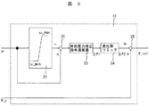
図2に速度制御器13の詳細な構成を示す。速度制御器13はリミッタ21と減算器22と有効電力修正指令演算器23と変化率リミッタ24と加算器25とを備えている。リミッタ21の入力は速度検出器11の検出する回転速度検出値ωであり、リミッタ21の上限値及び下限値は風車1の回転速度の上限値ω_max及び下限値ω_minでそれぞれ与えられる。減算器22は回転速度検出値ωとリミッタ21の出力との差分を演算する。有効電力修正指令演算器23は減算器22の出力に基づいて、有効電力修正指令ΔP1を演算する。有効電力修正指令演算器23は例えば比例積分制御系で構成され、さらにその入力が零になった場合はその積分値をリセットし、その出力を零にする。変化率リミッタ24は定常的には有効電力修正指令演算器23の出力する有効電力修正指令ΔP1をそのまま出力するが、その出力の変化率をある一定範囲内に抑える機能を備え、その出力をΔP2とする。加算器25は変化率リミッタの出力ΔP2と外部から与えられる有効電力指令P_cとを加算し、同期発電機2への有効電力指令P_refを出力する。
FIG. 2 shows a detailed configuration of the
次に、速度制御器13の動作を説明する。図3に速度制御器13の動作波形の例を示す。速度検出器11が検出する回転速度検出値ωがリミッタ21の上限値ω_maxと下限値ω_minとの間にある場合は減算器22の出力は零になるので、有効電力修正指令演算器23が出力する有効電力修正指令ΔP1はリセットされて零となり、変化率リミッタ24の出力ΔP2も定常的には零となる。従って、加算器25の出力P_ref は外部から与えられる有効電力指令P_c に一致する。すなわち、回転速度検出値ωが風車1の回転速度の上限値ω_maxと下限値ω_min の間にある場合は、速度制御器13は外部から与えられる有効電力指令P_cをそのまま同期発電機2への有効電力指令P_refとして出力する。
Next, the operation of the
一方、速度検出器11の検出する回転速度検出値ωがリミッタ21の上限値ω_maxよりも大きい場合は減算器22の出力は正となるので、有効電力修正指令演算器23の出力する有効電力修正指令ΔP1は増加し、変化率リミッタ24の出力ΔP2も増加する。従って、加算器25の出力P_refは外部から与えられる有効電力指令P_cよりも大きな値を出力する。すなわち、回転速度検出値ωが風車1の回転速度の上限値ω_max よりも大きい場合には、速度制御器13は同期発電機2への有効電力指令P_ref を増やす方向へ修正し、この修正は速度検出器11の検出する回転速度検出値ωがリミッタ21の上限値ω_max を下回るまで継続される。風から風車1のブレードへ与えられるパワーよりも同期発電機2の出力する有効電力が大きくなると、風車1の回転速度が減少するので、回転速度検出値ωが上限値ω_maxよりも大きい場合には風車1の回転速度を減少させる方向へ修正が働くことになる。
On the other hand, when the rotational speed detection value ω detected by the speed detector 11 is larger than the upper limit value ω_max of the
逆に、速度検出器11の検出する回転速度検出値ωがリミッタ21の下限値ω_minよりも小さい場合は減算器22の出力は負となるので、有効電力修正指令演算器23の出力する有効電力修正指令ΔP1は減少し、変化率リミッタ24の出力ΔP2も減少する。従って、加算器25の出力P_refは外部から与えられる有効電力指令P_cよりも小さな値を出力する。すなわち、回転速度検出値ωが風車1の回転速度の下限値ω_minよりも小さい場合には、速度制御器13は同期発電機2への有効電力指令P_refを減らす方向へ修正し、この修正は速度検出器11の検出する回転速度検出値ωがリミッタ21の下限値ω_min を上回るまで継続される。風から風車1のブレードへ与えられるパワーよりも同期発電機2の出力する有効電力が小さくなると、風車1の回転速度が増加するので、回転速度検出値ωが下限値ω_min よりも小さい場合には風車1の回転速度を増加させる方向へこの修正が働くことになる。
On the contrary, when the rotational speed detection value ω detected by the speed detector 11 is smaller than the lower limit value ω_min of the
以上の速度制御器13の動作により、風車1の回転速度が設定範囲を逸脱した場合に風車1の回転速度を設定範囲内で抑えるように速度制御を行い、風車1の回転速度が設定範囲内の場合は外部から与えられる有効電力指令に従って有効電力制御する。本実施例に示すように、風速が急変する場合にも風車の連続運転が可能なので、風車利用率が向上して、風車発電量の増加が図れ、風車発電コストを低減できる。さらに風車を連続運転できるので風車を系統に連系する開閉器等の動作回数が低減し、それらの機器の寿命を長くできる。
By the operation of the
図4に二次励磁発電機を用いた本実施例の全体構成を示す。図4において、二次励磁発電機26の回転子が風車1の軸に接続し、風車1が風速に応じた風のパワーで回転すると、固定子が電力系統に接続した二次励磁発電機26が系統周波数に一致した交流電力を電力系統に供給する。二次励磁発電機26の回転子には変換器27が接続し、変換器27が二次励磁発電機26の回転子を交流励磁する。変換器27は直流コンデンサ28を介し、変換器29に直流で接続し、変換器29は変換器27に励磁電力を供給する。変換器29は系統連系用変圧器6を介して電力系統に接続される。
FIG. 4 shows the overall configuration of this embodiment using a secondary excitation generator. In FIG. 4, when the rotor of the
二次励磁発電機26と変換器27との間には電圧検出センサ30と電流検出センサ31とが設置されており、電圧検出センサ30は二次励磁発電機26の回転子の端子電圧を、電流検出センサ31は二次励磁発電機26の回転子に流れる電流をそれぞれ検出する。検出した電圧値は3相/2相変換器32によってd軸成分Vr_dとq軸成分Vr_qとに変換され、検出した電流値は3相/2相変換器33によってd軸成分Ir_d とq軸成分Ir_qに変換される。
A
二次励磁発電機26と系統連系用変圧器6との間には電圧検出センサ35と電流検出センサ36が設置されており、電圧検出センサ35は系統電圧を、電流検出センサ36は電力系統へ流れる電流をそれぞれ検出する。検出した電圧値は3相/2相変換器37でd軸成分Vs_dとq軸成分Vs_qとに変換し、検出した電流値は3相/2相変換器38でd軸成分Is_dとq軸成分Is_qに変換する。
A
速度検出器34は3相/2相変換器32、33、37、38が出力するVr_d、Vr_q、Ir_d、Ir_q、Vs_d、Vs_q、Is_d、Is_qの信号に基づいて、風車1の回転速度ωと、二次励磁発電機26の回転子位相θrと、系統電圧位相θsとを検出する。
The
電力検出器12は3相/2相変換器37、38が出力するVs_d、Vs_q、Is_d、Is_qの信号に基づいて、二次励磁発電機26が出力する有効電力Pと無効電力Qとを検出する。
The
速度制御器13は、予め定められたパワーカーブと風車で計測された風速とから求めた出力に応じて外部から二次励磁発電機26へ与えられる有効電力指令P_c を、速度検出器34の検出する回転速度検出値ωに応じて修正し、二次励磁発電機26へ修正した有効電力指令P_ref を出力する。ここで、速度制御器13は、実施例1と同様の構成である。
The
無効電力指令演算器14は、速度制御器13が出力する二次励磁発電機26への有効電力指令P_refから二次励磁発電機26への無効電力指令Q_refを出力する。無効電力指令Q_refは系統との連系点の力率を調整するために設定される。
The reactive
有効電力制御器15の入力は、速度制御器13の出力する有効電力指令P_ref と電力検出器12の検出する有効電力検出値Pであり、有効電力制御器15の出力が変換器27への電流指令のq軸成分Ir_q_refになる。有効電力制御器15は例えば比例積分制御系により構成され、有効電力指令P_ref と有効電力検出値Pの偏差が零になるように変換器27への電流指令Ir_q_refを決定する。
The input of the
無効電力制御器16の入力は、無効電力指令演算器14が出力する無効電力指令Q_refと電力検出器12の検出する無効電力検出値Qであり、無効電力制御器16の出力が変換器27への電流指令のd軸成分Ir_d_refになる。無効電力制御器16は例えば比例積分制御系により構成され、無効電力指令Q_ref と無効電力検出値Qの偏差が零になるように変換器27への電流指令Ir_d_refを決定する。
The inputs of the
q軸電流制御器17の入力は、3相/2相変換器33が出力する電流検出値のq軸成分Ir_qと変換器27への電流指令のq軸成分Ir_q_ref であり、q軸電流制御器17の出力が変換器27への出力電圧指令のq軸成分Vr_q_refになる。q軸電流制御器17は例えば比例積分制御系により構成され、電流検出値Ir_qと電流指令Ir_q_refの偏差が零になるように変換器27への出力電圧指令Vr_q_refを決定する。
The inputs of the q-axis
d軸電流制御器18の入力は3相/2相変換器33が出力する電流検出値のd軸成分Ir_dと変換器27への電流指令のd軸成分Ir_d_ref であり、d軸電流制御器18の出力が変換器27への出力電圧指令のd軸成分Vr_d_refになる。d軸電流制御器18は例えば比例積分制御系により構成され、電流検出値Ir_d と電流指令Ir_d_refの偏差が零になるように変換器27への出力電圧指令Vr_d_refを決定する。
The inputs of the d-axis
q軸電流制御器17とd軸電流制御器18が出力する出力電圧指令のq軸成分Vr_q_refとd軸成分Vr_d_refとは2相/3相変換器19により3相の出力電圧指令Vr_uvw_refに変換される。
The q-axis component Vr_q_ref and the d-axis component Vr_d_ref of the output voltage command output from the q-axis
パルス発生器20は2相/3相変換器19が出力する3相の出力電圧指令Vr_uvw_refに基づいて、PWM(Pulse Width Modulation)により変換器27へのゲートパルス信号を出力する。変換器27はゲートパルス信号を受け、IGBT等の電力半導体スイッチング素子が高速にスイッチングを行うことで、変換器27は指令に応じた電圧を出力する。
The
本実施例でも、速度制御器13が実施例1と同様に動作するので、二次励磁発電機を用いた場合でも、風車1の回転速度が設定範囲を逸脱した場合には風車1の回転速度を設定範囲内で抑えるように速度制御を行い、風車1の回転速度が設定範囲内の場合は外部から与えられる有効電力指令に従って有効電力制御を行う。
Even in this embodiment, the
図5は本実施例の風力発電装置の全体構成を示す。本実施例は、同期発電機を用い、外部から与えられる指令が発電機へのトルク指令となる。図5に示すトルク検出器39は、3相/2相変換器9、10が出力するV_d、V_q、I_d、I_qの信号と、速度検出器11が検出した回転速度検出値ωとに基づいて、同期発電機2が出力するトルクTを検出する。
FIG. 5 shows the overall configuration of the wind turbine generator of this embodiment. In this embodiment, a synchronous generator is used, and a command given from the outside becomes a torque command to the generator. The
速度制御器40は外部から同期発電機2へ与えられるトルク指令T_c を速度検出器11の検出した回転速度検出値ωに応じて修正し、同期発電機2へ修正したトルク指令T_refを出力する。速度制御器40は実施例1や実施例2で説明した速度制御器13と同様に構成できる。
The
トルク制御器41の入力は、速度制御器40が出力したトルク指令T_ref とトルク検出器39が検出したトルク検出値Tであり、トルク制御器41の出力が、変換器3への電流指令のq軸成分I_q_refとなる。トルク制御器41は、例えば比例積分制御系により構成され、トルク指令T_ref とトルク検出値Tとの偏差が零になるように変換器3への電流指令I_q_refを決定する。
The input of the
d軸電流指令演算器42の入力は、トルク制御器41が出力する電流指令のq軸成分I_q_refであり、d軸電流指令演算器42の出力が変換器3への電流指令のd軸成分I_d_refとなる。電流指令のd軸成分I_d_refは同期発電機2の力率を調整するために設定される。
The input of the d-axis
本実施例の風力発電装置は、図5に示したその他の構成は図1と同様であり、外部から与えられる指令が発電機へのトルク指令の場合にも、風車1の回転速度が設定範囲を逸脱した場合に風車1の回転速度を設定範囲内に抑えるように速度制御を行い、風車1の回転速度が設定範囲内の場合は、外部から与えられるトルク指令に従ってトルク制御を行う。 The other configuration shown in FIG. 5 is the same as that of FIG. 1 in the wind turbine generator of this embodiment. Even when the command given from the outside is a torque command to the generator, the rotational speed of the wind turbine 1 is within the set range. If the rotational speed of the windmill 1 is within the set range, the speed control is performed according to the torque command given from the outside.
図6は本実施例の風力発電装置の全体構成を示す。本実施例は、二次励磁発電機を用い、外部から与えられる指令が発電機へのトルク指令となる。図6に示すトルク検出器39は3相/2相変換器37、38が出力するVs_d、Vs_q、Is_d、Is_qの信号と、速度検出器34が検出した回転速度検出値ωとに基づいて、二次励磁発電機26が出力するトルクTを検出する。
FIG. 6 shows the overall configuration of the wind turbine generator of this embodiment. In this embodiment, a secondary excitation generator is used, and a command given from the outside becomes a torque command to the generator. The
速度制御器40は外部から二次励磁発電機26へ与えられるトルク指令T_c を速度検出器34が検出した回転速度検出値ωに応じて修正し、二次励磁発電機26へ修正したトルク指令T_ref を出力する。速度制御器40は実施例1や実施例2で説明した速度制御器13と同様に構成できる。
The
トルク制御器41の入力は、速度制御器40が出力するトルク指令T_ref とトルク検出器39が検出するトルク検出値Tとであり、トルク制御器41の出力が変換器27への電流指令のq軸成分Ir_q_refとなる。トルク制御器41は、例えば比例積分制御系により構成され、トルク指令T_ref とトルク検出値Tの偏差が零になるように変換器27への電流指令Ir_q_refを決定する。
The input of the
d軸電流指令演算器42の入力は、トルク制御器41が出力する電流指令のq軸成分Ir_q_refであり、d軸電流指令演算器42の出力が変換器27への電流指令のd軸成分Ir_d_refとなる。電流指令のd軸成分Ir_d_refは系統との連系点の力率を調整するために設定される。
The input of the d-axis
本実施例の風力発電装置は、図6に示したその他の構成は図4と同様なので、外部から与えられる指令が発電機へのトルク指令の場合にも、風車1の回転速度が設定範囲を逸脱した場合には、風車1の回転速度を設定範囲内に抑えるように速度制御を行い、風車1の回転速度が設定範囲内の場合は外部から与えられるトルク指令に従ってトルク制御を行う。 The other configuration shown in FIG. 6 is the same as that of FIG. 4 in the wind power generator of the present embodiment. Therefore, even when the command given from the outside is a torque command to the generator, the rotational speed of the windmill 1 falls within the set range. When deviating, speed control is performed so that the rotational speed of the windmill 1 is kept within the set range, and when the rotational speed of the windmill 1 is within the set range, torque control is performed according to a torque command given from the outside.
図7に、本実施例の風力発電装置の全体構成を示す。本実施例は二次励磁発電機を用い、外部から与えられる指令が発電機への有効電力指令の場合である。図7に示すように、電圧検出センサ43及び電流検出センサ44の配置が図4に示す実施例2と異なるが、これ以外は実施例2と同様である。図7に示す本実施例でも、風車1の回転速度が設定範囲を逸脱した場合には風車1の回転速度を設定範囲内で抑えるように速度制御を行い、風車1の回転速度が設定範囲内の場合は外部から与えられる有効電力指令に従って有効電力制御を行う。
In FIG. 7, the whole structure of the wind power generator of a present Example is shown. In this embodiment, a secondary excitation generator is used, and the command given from the outside is an active power command to the generator. As shown in FIG. 7, the arrangement of the
図8に、本実施例の風力発電装置の全体構成を示す。本実施例は二次励磁発電機を用い、外部から与えられる指令が発電機へのトルク指令の場合である。本実施例は図8に示すように、電圧検出センサ43と電流検出センサ44の配置が図6に示す実施例4と異なるが、これ以外は実施例4と同様である。図8に示す本実施例でも、風車1の回転速度が設定範囲を逸脱した場合に風車1の回転速度を設定範囲内で抑えるように速度制御を行い、風車1の回転速度が設定範囲内の場合は外部から与えられるトルク指令に従ってトルク制御を行う。
In FIG. 8, the whole structure of the wind power generator of a present Example is shown. In this embodiment, a secondary excitation generator is used, and a command given from the outside is a torque command to the generator. As shown in FIG. 8, the present embodiment is the same as the fourth embodiment except that the arrangement of the
1…風車、2…同期発電機、3,5,27,29…変換器、4,28…直流コンデンサ、6…系統連系用変圧器、7,30,35,43…電圧検出センサ、8,31,36,44…電流検出センサ、9,10,32,33,37,38…3相/2相変換器、11,34,45…速度検出器、12,46…電力検出器、13,40…速度制御器、14…無効電力指令演算器、15…有効電力制御器、16…無効電力制御器、17…q軸電流制御器、18…d軸電流制御器、19…2相/3相変換器、20…パルス発生器、21…リミッタ、22…減算器、23…有効電力修正指令演算器、24…変化率リミッタ、25…加算器、26…二次励磁発電機、39,47…トルク検出器、41…トルク制御器、42…d軸電流指令演算器。
DESCRIPTION OF SYMBOLS 1 ... Windmill, 2 ... Synchronous generator, 3, 5, 27, 29 ... Converter, 4, 28 ... DC capacitor, 6 ... Transformer for system connection, 7, 30, 35, 43 ... Voltage detection sensor, 8 , 31, 36, 44 ... current detection sensor, 9, 10, 32, 33, 37, 38 ... 3-phase / 2-phase converter, 11, 34, 45 ... speed detector, 12, 46 ... power detector, 13 , 40 ... Speed controller, 14 ... Reactive power command calculator, 15 ... Active power controller, 16 ... Reactive power controller, 17 ... q-axis current controller, 18 ... d-axis current controller, 19 ... 2-phase / Three-phase converter, 20 ... Pulse generator, 21 ... Limiter, 22 ... Subtractor, 23 ... Active power correction command calculator, 24 ... Change rate limiter, 25 ... Adder, 26 ... Secondary excitation generator, 39, 47 ... Torque detector, 41 ... Torque controller, 42 ... d-axis current command calculator.
Claims (2)
前記制御装置が、前記風車の回転速度を検出する速度検出器と、前記速度検出器が出力する速度検出値を入力する速度制御器と、前記同期発電機が出力する電力を検出する電力検出器と、前記電力検出器が出力する有効電力検出値を入力する有効電力制御器とを備え、A speed detector for detecting a rotational speed of the windmill; a speed controller for inputting a speed detection value output by the speed detector; and a power detector for detecting power output by the synchronous generator. And an active power controller for inputting an active power detection value output by the power detector,
前記速度制御器は、前記速度検出値が所定の領域にある場合には、発電機出力に関する指令を前記有効電力制御器へ有効電力指令として出力し、前記速度検出値が所定の領域から外れる場合には、発電機出力に関する指令を前記速度検出値に基づいて修正し、該修正した指令を前記有効電力制御器へ有効電力指令として出力することを特徴とする風力発電装置。When the speed detection value is in a predetermined region, the speed controller outputs a command relating to a generator output to the active power controller as an active power command, and the speed detection value is out of the predetermined region. In the wind power generator, the command relating to the generator output is corrected based on the speed detection value, and the corrected command is output to the active power controller as the active power command.
前記制御装置が、前記風車の回転速度を検出する速度検出器と、前記速度検出器が出力する速度検出値を入力する速度制御器と、前記二次励磁発電機が出力する電力を検出する電力検出器と、前記電力検出器が出力する有効電力検出値を入力する有効電力制御器とを備え、The control device detects a rotational speed of the windmill, a speed controller that inputs a speed detection value output from the speed detector, and an electric power that detects power output from the secondary excitation generator A detector, and an active power controller that inputs an active power detection value output by the power detector,
前記速度制御器は、前記速度検出値が所定の領域にある場合には、発電機出力に関する指令を前記有効電力制御器へ有効電力指令として出力し、前記速度検出値が所定の領域から外れる場合には、発電機出力に関する指令を前記速度検出値に基づいて修正し、該修正した指令を前記有効電力制御器へ有効電力指令として出力することを特徴とする風力発電装置。When the speed detection value is in a predetermined region, the speed controller outputs a command relating to a generator output to the active power controller as an active power command, and the speed detection value is out of the predetermined region. In the wind power generator, the command relating to the generator output is corrected based on the speed detection value, and the corrected command is output to the active power controller as the active power command.
Priority Applications (7)
| Application Number | Priority Date | Filing Date | Title |
|---|---|---|---|
| JP2004230058A JP3918837B2 (en) | 2004-08-06 | 2004-08-06 | Wind power generator |
| DE102005034635A DE102005034635A1 (en) | 2004-08-06 | 2005-07-25 | Generator system for wind turbine |
| US11/196,250 US7268443B2 (en) | 2004-08-06 | 2005-08-04 | Wind turbine generator system |
| US11/774,868 US7615880B2 (en) | 2004-08-06 | 2007-07-09 | Wind turbine generator system |
| US12/582,199 US7952216B2 (en) | 2004-08-06 | 2009-10-20 | Wind turbine generator system |
| US13/117,961 US8242620B2 (en) | 2004-08-06 | 2011-05-27 | Wind turbine generator system |
| US13/556,873 US8466573B2 (en) | 2004-08-06 | 2012-07-24 | Wind turbine generator system |
Applications Claiming Priority (1)
| Application Number | Priority Date | Filing Date | Title |
|---|---|---|---|
| JP2004230058A JP3918837B2 (en) | 2004-08-06 | 2004-08-06 | Wind power generator |
Related Child Applications (1)
| Application Number | Title | Priority Date | Filing Date |
|---|---|---|---|
| JP2006339386A Division JP4386068B2 (en) | 2006-12-18 | 2006-12-18 | Wind power generator, control method for wind power generator, control device |
Publications (3)
| Publication Number | Publication Date |
|---|---|
| JP2006050835A JP2006050835A (en) | 2006-02-16 |
| JP2006050835A5 JP2006050835A5 (en) | 2006-11-02 |
| JP3918837B2 true JP3918837B2 (en) | 2007-05-23 |
Family
ID=35721676
Family Applications (1)
| Application Number | Title | Priority Date | Filing Date |
|---|---|---|---|
| JP2004230058A Active JP3918837B2 (en) | 2004-08-06 | 2004-08-06 | Wind power generator |
Country Status (3)
| Country | Link |
|---|---|
| US (5) | US7268443B2 (en) |
| JP (1) | JP3918837B2 (en) |
| DE (1) | DE102005034635A1 (en) |
Families Citing this family (93)
| Publication number | Priority date | Publication date | Assignee | Title |
|---|---|---|---|---|
| NZ528765A (en) * | 2001-04-20 | 2006-11-30 | Aloys Wobben | Method for operating a wind energy plant in which the power is regulated in response to a current supplied to a load |
| DE10119624A1 (en) * | 2001-04-20 | 2002-11-21 | Aloys Wobben | Operating wind energy plant involves regulating power delivered from generator to electrical load, especially of electrical network, depending on current delivered to the load |
| DK1433238T3 (en) * | 2001-09-28 | 2017-08-21 | Wobben Properties Gmbh | Procedure for operating a wind farm |
| JP4168252B2 (en) * | 2002-12-27 | 2008-10-22 | 株式会社安川電機 | Power generation system and control method thereof |
| US7119452B2 (en) * | 2003-09-03 | 2006-10-10 | General Electric Company | Voltage control for wind generators |
| JP3918837B2 (en) * | 2004-08-06 | 2007-05-23 | 株式会社日立製作所 | Wind power generator |
| US7215035B2 (en) * | 2005-02-22 | 2007-05-08 | Xantrex Technology, Inc. | Method and apparatus for converting wind generated electricity to constant frequency electricity for a utility grid |
| US7476985B2 (en) * | 2005-07-22 | 2009-01-13 | Gamesa Innovation & Technology, S.L. | Method of operating a wind turbine |
| WO2007035411A2 (en) * | 2005-09-16 | 2007-03-29 | Satcon Technology Corporation | Slip-controlled, wound-rotor induction machine for wind turbine and other applications |
| ITBZ20050063A1 (en) * | 2005-11-29 | 2007-05-30 | High Technology Invest Bv | LAMIERINI PACKAGE FOR GENERATORS AND ELECTRIC MOTORS AND PROCEDURE FOR ITS IMPLEMENTATION |
| ITBZ20050062A1 (en) * | 2005-11-29 | 2007-05-30 | High Technology Invest Bv | PERMANENT MAGNET ROTOR FOR GENERATORS AND ELECTRIC MOTORS |
| DE602006013011D1 (en) * | 2005-09-21 | 2010-04-29 | High Technology Invest Bv | BEARING SEALING ASSEMBLY WITH LABYRINTH SEALING AND SCREW SEALING COMBINATION |
| JP4738206B2 (en) * | 2006-02-28 | 2011-08-03 | 三菱重工業株式会社 | Wind power generation system and control method thereof |
| JP2008011607A (en) | 2006-06-28 | 2008-01-17 | Hitachi Ltd | Speed-variable wind turbine power generation system |
| US20080064131A1 (en) * | 2006-09-12 | 2008-03-13 | Mutual-Tek Industries Co., Ltd. | Light emitting apparatus and method for the same |
| JP4365394B2 (en) * | 2006-09-20 | 2009-11-18 | 株式会社日立製作所 | Wind power generation system and operation method thereof |
| US7642666B2 (en) * | 2006-11-02 | 2010-01-05 | Hitachi, Ltd. | Wind power generation apparatus, wind power generation system and power system control apparatus |
| DE102006060323A1 (en) * | 2006-12-20 | 2008-06-26 | Nordex Energy Gmbh | Method for operating wind energy plant, involves transmitting driving torque to generator over power train, where generator provides predetermined generator torque acting opposite driving torque |
| BRPI0622196A2 (en) * | 2006-12-22 | 2012-01-03 | High Technology Invest Bv | wind turbine with multiple generators |
| JP2008301584A (en) * | 2007-05-30 | 2008-12-11 | Hitachi Ltd | Wind turbine generator system and control method for power converter |
| DE602007009966D1 (en) * | 2007-07-16 | 2010-12-02 | Gamesa Innovation & Tech Sl | Wind power system and operating method therefor |
| DE102007049251A1 (en) * | 2007-10-12 | 2009-04-23 | Repower Systems Ag | Wind turbines with regulation for network faults and operating methods therefor |
| DE102008004269A1 (en) * | 2008-01-14 | 2009-07-16 | Generator-Technik Schwäb. Gmünd GmbH & Co. | Power supply device for e.g. ventilator, in e.g. vehicle, has power converter for adjusting excitation of generator depending on value measured at output of generator and voltage value measured in voltage intermediate circuit |
| DE102008034532A1 (en) * | 2008-02-20 | 2009-08-27 | Repower Systems Ag | Wind turbine with inverter control |
| DE102008010543A1 (en) * | 2008-02-22 | 2009-08-27 | Nordex Energy Gmbh | Method for operating a wind turbine and wind turbine |
| DE102008013415A1 (en) * | 2008-03-10 | 2009-05-07 | Siemens Aktiengesellschaft | Wind turbine controlling method, involves producing moment-reference value as input variable for moment-controlled converter, and reducing speed-fluctuation-related deviation of speed-actual value from speed-reference value by multiplier |
| ES2327486B1 (en) * | 2008-03-14 | 2010-07-14 | Ingeteam Energy, S.A. | METHOD OF OPERATION OF A WIND TURBINE TO GUARANTEE PRIMARY OR SECONDARY REGULATION IN AN ELECTRICAL NETWORK. |
| US7977925B2 (en) * | 2008-04-04 | 2011-07-12 | General Electric Company | Systems and methods involving starting variable speed generators |
| ITMI20081122A1 (en) * | 2008-06-19 | 2009-12-20 | Rolic Invest Sarl | WIND GENERATOR PROVIDED WITH A COOLING SYSTEM |
| IT1390758B1 (en) | 2008-07-23 | 2011-09-23 | Rolic Invest Sarl | WIND GENERATOR |
| DE102008037449B4 (en) | 2008-10-14 | 2010-10-14 | Kenersys Gmbh | Wind turbine |
| KR101253854B1 (en) * | 2008-10-16 | 2013-04-12 | 미츠비시 쥬고교 가부시키가이샤 | Wind power generation system, and its control method |
| US8058753B2 (en) * | 2008-10-31 | 2011-11-15 | General Electric Company | Wide area transmission control of windfarms |
| IT1391939B1 (en) * | 2008-11-12 | 2012-02-02 | Rolic Invest Sarl | WIND GENERATOR |
| IT1391770B1 (en) | 2008-11-13 | 2012-01-27 | Rolic Invest Sarl | WIND GENERATOR FOR THE GENERATION OF ELECTRICITY |
| US7804184B2 (en) * | 2009-01-23 | 2010-09-28 | General Electric Company | System and method for control of a grid connected power generating system |
| IT1392804B1 (en) * | 2009-01-30 | 2012-03-23 | Rolic Invest Sarl | PACKAGING AND PACKAGING METHOD FOR POLE OF WIND GENERATORS |
| EP2391818B1 (en) * | 2009-01-30 | 2013-03-27 | DeWind Co. | Adaptive voltage control for wind turbines |
| IT1393937B1 (en) * | 2009-04-09 | 2012-05-17 | Rolic Invest Sarl | WIND TURBINE |
| IT1393707B1 (en) | 2009-04-29 | 2012-05-08 | Rolic Invest Sarl | WIND POWER PLANT FOR THE GENERATION OF ELECTRICITY |
| CN101970865B (en) * | 2009-05-20 | 2013-11-06 | 三菱重工业株式会社 | Wind turbine generator and control method thereof |
| JP2010275926A (en) * | 2009-05-28 | 2010-12-09 | Zephyr Corp | Wind power generation control device and wind power generation control method |
| IT1394723B1 (en) | 2009-06-10 | 2012-07-13 | Rolic Invest Sarl | WIND POWER PLANT FOR THE GENERATION OF ELECTRICITY AND ITS CONTROL METHOD |
| US7863766B2 (en) * | 2009-06-30 | 2011-01-04 | Teco-Westinghouse Motor Company | Power converter for use with wind generator |
| US10435145B1 (en) | 2009-07-02 | 2019-10-08 | Alfred Finnell | Vehicle with tension wing assembly |
| US11021243B1 (en) | 2009-07-02 | 2021-06-01 | Alfred Finnell | Tension airfoil assembly and implementation for power generation and aviation |
| US10443569B1 (en) * | 2009-07-02 | 2019-10-15 | Alfred Finnell | Wind or water based power generating system |
| IT1395148B1 (en) * | 2009-08-07 | 2012-09-05 | Rolic Invest Sarl | METHOD AND APPARATUS FOR ACTIVATION OF AN ELECTRIC MACHINE AND ELECTRIC MACHINE |
| ES2537126T3 (en) * | 2009-08-14 | 2015-06-02 | Vestas Wind Systems A/S | Variable speed wind turbine and method for operating the variable speed wind turbine during a power imbalance event |
| US8759994B2 (en) | 2009-09-18 | 2014-06-24 | Vestas Wind Systems A/S | Method of controlling a wind turbine generator and apparatus for controlling electric power generated by a wind turbine generator |
| IT1397013B1 (en) * | 2009-11-03 | 2012-12-20 | Trevi Energy S P A | CONTROL SYSTEM OF WIND POWER PLANT WITH AIRCONDITIONER EQUIPPED WITH MODULAR DIRECT CURRENT CONVERTERS. |
| IT1397081B1 (en) | 2009-11-23 | 2012-12-28 | Rolic Invest Sarl | WIND POWER PLANT FOR THE GENERATION OF ELECTRICITY |
| IT1398060B1 (en) | 2010-02-04 | 2013-02-07 | Wilic Sarl | PLANT AND METHOD OF COOLING OF AN ELECTRIC GENERATOR OF AN AIR SPREADER, AND AIRCONDITIONER INCLUDING SUCH A COOLING PLANT |
| IT1399201B1 (en) | 2010-03-30 | 2013-04-11 | Wilic Sarl | AEROGENERATOR AND METHOD OF REMOVING A BEARING FROM A AIRCONDITIONER |
| IT1399511B1 (en) | 2010-04-22 | 2013-04-19 | Wilic Sarl | ELECTRIC GENERATOR FOR A VENTILATOR AND AEROGENER EQUIPPED WITH THIS ELECTRIC GENERATOR |
| DE102010021865B4 (en) * | 2010-05-28 | 2024-03-21 | Sew-Eurodrive Gmbh & Co Kg | Method for controlling or braking a synchronous machine and a converter-fed synchronous machine |
| DE102011002650B4 (en) | 2011-01-13 | 2023-12-07 | Ford Global Technologies, Llc | motor vehicle |
| AU2011202373A1 (en) * | 2011-02-28 | 2012-09-13 | Mitsubishi Heavy Industries, Ltd. | Wind turbine generator and method of controlling the same |
| ITMI20110378A1 (en) | 2011-03-10 | 2012-09-11 | Wilic Sarl | ROTARY ELECTRIC MACHINE FOR AEROGENERATOR |
| ITMI20110375A1 (en) | 2011-03-10 | 2012-09-11 | Wilic Sarl | WIND TURBINE |
| ITMI20110377A1 (en) | 2011-03-10 | 2012-09-11 | Wilic Sarl | ROTARY ELECTRIC MACHINE FOR AEROGENERATOR |
| TW201241457A (en) * | 2011-04-14 | 2012-10-16 | Univ Chung Yuan Christian | Rotating electrical machine anomaly detecting method and apparatus, and wind generating system |
| FR2977094B1 (en) * | 2011-06-23 | 2013-07-12 | Alstom Hydro France | METHOD OF CONTROLLING THE POWER OF AN ENERGY CONVERSION INSTALLATION AND A POWER-CONVERSION INSTALLATION PILOTED BY SUCH A METHOD |
| US8258643B2 (en) * | 2011-10-11 | 2012-09-04 | General Electric Company | Method and system for control of wind turbines |
| ES2407955B1 (en) * | 2011-12-12 | 2014-05-08 | Acciona Windpower, S.A. | AEROGENERATOR CONTROL PROCEDURE |
| JP5868170B2 (en) * | 2011-12-28 | 2016-02-24 | 大阪瓦斯株式会社 | Cogeneration system and control method thereof |
| TWI515370B (en) * | 2012-03-01 | 2016-01-01 | 台達電子工業股份有限公司 | Blade speed control system and control method thereof |
| EP2636893B1 (en) | 2012-03-07 | 2016-08-31 | Siemens Aktiengesellschaft | Method to control the operation of a wind turbine |
| EP2824322B1 (en) * | 2012-03-08 | 2016-11-16 | Mitsubishi Heavy Industries, Ltd. | Output control device and output control method for windmill |
| US10591519B2 (en) | 2012-05-29 | 2020-03-17 | Nutech Ventures | Detecting faults in wind turbines |
| US10359473B2 (en) | 2012-05-29 | 2019-07-23 | Nutech Ventures | Detecting faults in turbine generators |
| DK2672624T3 (en) * | 2012-06-05 | 2014-12-01 | Siemens Ag | Power regulator and generator system |
| US8976503B2 (en) * | 2012-08-07 | 2015-03-10 | Textron Systems Corporation | Voltage monitoring for fireset |
| US8704393B2 (en) | 2012-08-09 | 2014-04-22 | General Electric Company | System and method for controlling speed and torque of a wind turbine during post-rated wind speed conditions |
| US9371821B2 (en) | 2012-08-31 | 2016-06-21 | General Electric Company | Voltage control for wind turbine generators |
| DE102013204600A1 (en) * | 2013-03-15 | 2014-09-18 | Senvion Se | Wind turbine with frequency measurement |
| CN103353561B (en) * | 2013-06-24 | 2016-09-28 | 国家电网公司 | A kind of alternating-current loops of wind generation set detecting system and detection method thereof |
| DE102013215398A1 (en) * | 2013-08-06 | 2015-02-12 | Wobben Properties Gmbh | Method for controlling wind turbines |
| DE102015201836A1 (en) * | 2015-02-03 | 2016-08-04 | Siemens Aktiengesellschaft | Method and device for monitoring the operation of a power plant |
| DE102015205348A1 (en) * | 2015-03-24 | 2016-09-29 | Wobben Properties Gmbh | Method for controlling a synchronous generator of a gearless wind turbine |
| GB2539204B (en) * | 2015-06-08 | 2021-03-24 | Ec Power As | Starter for a combined heat and power unit |
| DE102016101469A1 (en) * | 2016-01-27 | 2017-07-27 | Wobben Properties Gmbh | Method for feeding electrical power into an electrical supply network |
| DK3516211T3 (en) * | 2016-09-19 | 2023-05-22 | Gen Electric | WINDMILL AND PROCEDURE FOR CONTROLLING A WINDMILL |
| DE102016122580A1 (en) * | 2016-11-23 | 2018-05-24 | Wobben Properties Gmbh | Method for feeding electrical power into an electrical supply network |
| EP3382198A4 (en) | 2016-12-13 | 2019-11-13 | Obshchestvo S Ogranichennoj Otvetstvennostyu "VDM-Tekhnika" | Method of adjusting wind turbine power take-off |
| US10852214B2 (en) | 2017-05-19 | 2020-12-01 | Nutech Ventures | Detecting faults in wind turbines |
| JP6796029B2 (en) * | 2017-06-13 | 2020-12-02 | 株式会社日立製作所 | New energy source integrated power converter |
| JP7012513B2 (en) * | 2017-11-13 | 2022-01-28 | 株式会社日立製作所 | Hydropower system |
| CN108223277A (en) * | 2017-12-29 | 2018-06-29 | 华润电力风能(惠来)有限公司 | A kind of wind power generating set method for enhancing power and relevant device |
| CN110768308B (en) * | 2018-07-26 | 2023-07-18 | 通用电气公司 | System and method for controlling an electrical power system connected to an electrical grid |
| RU2730751C1 (en) * | 2019-06-10 | 2020-08-25 | Федеральное государственное автономное образовательное учреждение высшего образования "Балтийский федеральный университет имени Иммануила Канта" (БФУ им. И. Канта) | Wind-driven generator control system |
| KR102243317B1 (en) * | 2019-11-29 | 2021-04-21 | 재단법인 녹색에너지연구원 | Frequency Control System and Control Method of Variable Speed Wind Power Generator |
| CN111585297A (en) * | 2020-06-12 | 2020-08-25 | 阳光电源股份有限公司 | Direct-current coupling hydrogen production system and control method thereof |
Family Cites Families (103)
| Publication number | Priority date | Publication date | Assignee | Title |
|---|---|---|---|---|
| US1914095A (en) * | 1930-11-17 | 1933-06-13 | Westinghouse Electric & Mfg Co | Regulator system |
| US2063077A (en) * | 1935-04-23 | 1936-12-08 | Gen Electric | Electrical regulating system |
| US3242417A (en) * | 1962-09-14 | 1966-03-22 | Bbc Brown Boveri & Cie | Automatic power control for high frequency alternators |
| US4400659A (en) * | 1980-05-30 | 1983-08-23 | Benjamin Barron | Methods and apparatus for maximizing and stabilizing electric power derived from wind driven source |
| US4388585A (en) * | 1981-03-16 | 1983-06-14 | The United States Of America As Represented By The Administrator Of The National Aeronautics And Space Administration | Electrical power generating system |
| US4525633A (en) * | 1982-09-28 | 1985-06-25 | Grumman Aerospace Corporation | Wind turbine maximum power tracking device |
| US4541052A (en) * | 1982-12-20 | 1985-09-10 | General Motors Corporation | Motor vehicle power output regulation control system |
| JPS61149583A (en) * | 1984-12-21 | 1986-07-08 | Hitachi Ltd | Starting method for variable speed reversible pump-turbine or pump |
| US4695736A (en) * | 1985-11-18 | 1987-09-22 | United Technologies Corporation | Variable speed wind turbine |
| US4700081A (en) * | 1986-04-28 | 1987-10-13 | United Technologies Corporation | Speed avoidance logic for a variable speed wind turbine |
| DE3770332D1 (en) * | 1986-04-30 | 1991-07-04 | Hitachi Ltd | ENERGY GENERATOR SYSTEM OF THE PUMP SURVEY TYPE WITH VARIABLE SPEED. |
| JPS62282172A (en) * | 1986-05-12 | 1987-12-08 | Hitachi Ltd | Variable speed water-wheel generator |
| US4656413A (en) * | 1986-06-19 | 1987-04-07 | Bourbeau Frank J | Stabilized control system and method for coupling an induction generator to AC power mains |
| US4710686A (en) * | 1986-08-04 | 1987-12-01 | Guzik Technical Enterprises | Method and apparatus for control of current in a motor winding |
| JP2585233B2 (en) * | 1986-10-17 | 1997-02-26 | 株式会社日立製作所 | Variable speed turbine generator |
| DE3855290T2 (en) * | 1987-08-14 | 1996-11-21 | Hitachi Ltd | Control system for a variable speed hydro power plant |
| US4994684A (en) * | 1989-01-30 | 1991-02-19 | The State Of Oregon Acting By And Through The State Board Of Higher Education On Behalf Of Oregon State University | Doubly fed generator variable speed generation control system |
| US5028804A (en) * | 1989-06-30 | 1991-07-02 | The State Of Oregon Acting By And Through The State Board Of Higher Education On Behalf Of Oregon State University | Brushless doubly-fed generator control system |
| JP2714449B2 (en) * | 1989-08-08 | 1998-02-16 | 株式会社日立製作所 | Variable speed pump system |
| US5083039B1 (en) * | 1991-02-01 | 1999-11-16 | Zond Energy Systems Inc | Variable speed wind turbine |
| US5155375A (en) * | 1991-09-19 | 1992-10-13 | U.S. Windpower, Inc. | Speed control system for a variable speed wind turbine |
| WO1994004819A1 (en) * | 1992-08-18 | 1994-03-03 | Four Winds Energy Corporation | Wind turbine particularly suited for high-wind conditions |
| US5255712A (en) * | 1992-10-28 | 1993-10-26 | Foster Raymond K | Check valve pull assembly |
| US5418446A (en) * | 1993-05-10 | 1995-05-23 | Hallidy; William M. | Variable speed constant frequency synchronous electric power generating system and method of using same |
| US5663631A (en) * | 1994-07-19 | 1997-09-02 | Nippondenso Co., Ltd. | Generator with circuitry for controlling power generation based on rotational speed |
| US5757641A (en) * | 1995-07-03 | 1998-05-26 | General Electric Company | Triplex control system with sensor failure compensation |
| US5798631A (en) * | 1995-10-02 | 1998-08-25 | The State Of Oregon Acting By And Through The State Board Of Higher Education On Behalf Of Oregon State University | Performance optimization controller and control method for doubly-fed machines |
| US6420795B1 (en) * | 1998-08-08 | 2002-07-16 | Zond Energy Systems, Inc. | Variable speed wind turbine generator |
| US6600240B2 (en) * | 1997-08-08 | 2003-07-29 | General Electric Company | Variable speed wind turbine generator |
| US6137187A (en) * | 1997-08-08 | 2000-10-24 | Zond Energy Systems, Inc. | Variable speed wind turbine generator |
| DE19756777B4 (en) * | 1997-12-19 | 2005-07-21 | Wobben, Aloys, Dipl.-Ing. | Method for operating a wind energy plant and wind energy plant |
| DK199901436A (en) * | 1999-10-07 | 2001-04-08 | Vestas Wind System As | Wind turbine |
| NO20001641L (en) | 2000-03-29 | 2001-10-01 | Abb Research Ltd | Wind power plants |
| EP1284045A1 (en) * | 2000-05-23 | 2003-02-19 | Vestas Wind System A/S | Variable speed wind turbine having a matrix converter |
| JP2002233193A (en) | 2001-01-31 | 2002-08-16 | Mitsubishi Heavy Ind Ltd | Wind power generator |
| JP4003414B2 (en) * | 2001-06-29 | 2007-11-07 | 株式会社日立製作所 | Power generator using permanent magnet generator |
| JP3909465B2 (en) * | 2001-07-26 | 2007-04-25 | 株式会社日立製作所 | Gas turbine system and control method thereof |
| WO2003026121A1 (en) * | 2001-09-14 | 2003-03-27 | Edwin Sweo | Brushless doubly-fed induction machine control |
| US6703718B2 (en) * | 2001-10-12 | 2004-03-09 | David Gregory Calley | Wind turbine controller |
| US7015595B2 (en) * | 2002-02-11 | 2006-03-21 | Vestas Wind Systems A/S | Variable speed wind turbine having a passive grid side rectifier with scalar power control and dependent pitch control |
| US20030209912A1 (en) * | 2002-05-07 | 2003-11-13 | Randall Badger | Wind power electrical generating system |
| US7071579B2 (en) * | 2002-06-07 | 2006-07-04 | Global Energyconcepts,Llc | Wind farm electrical system |
| JP3914106B2 (en) * | 2002-07-08 | 2007-05-16 | 株式会社日立製作所 | Gas turbine power generation system and control method thereof |
| JP4168252B2 (en) * | 2002-12-27 | 2008-10-22 | 株式会社安川電機 | Power generation system and control method thereof |
| US6954004B2 (en) * | 2003-01-23 | 2005-10-11 | Spellman High Voltage Electronics Corporation | Doubly fed induction machine |
| US6940185B2 (en) * | 2003-04-10 | 2005-09-06 | Advantek Llc | Advanced aerodynamic control system for a high output wind turbine |
| EP1625457A4 (en) * | 2003-05-02 | 2015-04-22 | Xantrex Technology Inc | Control system for doubly fed induction generator |
| US7042110B2 (en) * | 2003-05-07 | 2006-05-09 | Clipper Windpower Technology, Inc. | Variable speed distributed drive train wind turbine system |
| JP4007268B2 (en) * | 2003-07-22 | 2007-11-14 | 株式会社日立製作所 | Wind power generator |
| US7528496B2 (en) * | 2003-09-03 | 2009-05-05 | Repower Systems Ag | Method for operating or controlling a wind turbine and method for providing primary control power by means of wind turbines |
| JP4269941B2 (en) * | 2004-01-08 | 2009-05-27 | 株式会社日立製作所 | Wind power generator and control method thereof |
| JP3918837B2 (en) * | 2004-08-06 | 2007-05-23 | 株式会社日立製作所 | Wind power generator |
| DE102004054608B4 (en) * | 2004-09-21 | 2006-06-29 | Repower Systems Ag | Method for controlling a wind turbine and wind turbine with a rotor |
| DE102005044892A1 (en) * | 2004-09-21 | 2006-03-30 | Denso Corp., Kariya | Method and system for controlling the energy supplied to electrical loads |
| US7859125B2 (en) * | 2004-12-28 | 2010-12-28 | Vestas Wind Systems A/S | Method of controlling a wind turbine connected to an electric utility grid |
| DE102005029000B4 (en) * | 2005-06-21 | 2007-04-12 | Repower Systems Ag | Method and system for regulation of rotational speed of rotor on wind energy unit with generator and energy blade using pitch angle control device and torque control device to determine rotational speed set values |
| US7342323B2 (en) * | 2005-09-30 | 2008-03-11 | General Electric Company | System and method for upwind speed based control of a wind turbine |
| US7511385B2 (en) * | 2005-11-11 | 2009-03-31 | Converteam Ltd | Power converters |
| US7372174B2 (en) * | 2005-11-11 | 2008-05-13 | Converteam Ltd | Power converters |
| US7396028B2 (en) * | 2005-11-16 | 2008-07-08 | Dana Heavy Vehicle Systems Group Llc | Lifting system for a vehicle axle |
| US7345373B2 (en) * | 2005-11-29 | 2008-03-18 | General Electric Company | System and method for utility and wind turbine control |
| JP4738206B2 (en) * | 2006-02-28 | 2011-08-03 | 三菱重工業株式会社 | Wind power generation system and control method thereof |
| US7352075B2 (en) * | 2006-03-06 | 2008-04-01 | General Electric Company | Methods and apparatus for controlling rotational speed of a rotor |
| US7425771B2 (en) * | 2006-03-17 | 2008-09-16 | Ingeteam S.A. | Variable speed wind turbine having an exciter machine and a power converter not connected to the grid |
| JP2008011607A (en) * | 2006-06-28 | 2008-01-17 | Hitachi Ltd | Speed-variable wind turbine power generation system |
| ES2693433T3 (en) * | 2006-07-06 | 2018-12-11 | Acciona Windpower, S.A. | Systems, procedures and devices for a wind turbine controller |
| US7352076B1 (en) * | 2006-08-11 | 2008-04-01 | Mariah Power Inc. | Small wind turbine system |
| US7642666B2 (en) * | 2006-11-02 | 2010-01-05 | Hitachi, Ltd. | Wind power generation apparatus, wind power generation system and power system control apparatus |
| WO2008064472A1 (en) * | 2006-11-28 | 2008-06-05 | The Royal Institution For The Advancement Of Learning/Mcgill University | Method and system for controlling a doubly-fed induction machine |
| JP5215554B2 (en) * | 2006-12-14 | 2013-06-19 | 株式会社日立製作所 | Wind power generator and power converter |
| WO2008077974A1 (en) * | 2006-12-22 | 2008-07-03 | Wind To Power System, S.L. | Asynchronous generator with double supply |
| JP4486654B2 (en) * | 2007-01-29 | 2010-06-23 | 株式会社日立製作所 | Electric motor control system, series hybrid vehicle, electric motor control device, and electric motor control method |
| DE102007014728A1 (en) * | 2007-03-24 | 2008-10-02 | Woodward Seg Gmbh & Co. Kg | Method and device for operating a double-fed asynchronous machine in transient mains voltage changes |
| EP2140137B1 (en) * | 2007-04-30 | 2013-04-10 | Vestas Wind Systems A/S | Variable speed wind turbine with doubly-fed induction generator compensated for varying rotor speed |
| WO2008137836A1 (en) * | 2007-05-04 | 2008-11-13 | The University Of Alabama | Converter control of variable-speed wind turbines |
| JP5022102B2 (en) * | 2007-05-25 | 2012-09-12 | 三菱重工業株式会社 | Wind power generator, wind power generator system, and power generation control method for wind power generator |
| JP2008301584A (en) * | 2007-05-30 | 2008-12-11 | Hitachi Ltd | Wind turbine generator system and control method for power converter |
| ES2571935T3 (en) * | 2007-06-01 | 2016-05-27 | Acciona Windpower Sa | Wind turbine control system and procedure |
| US7847526B2 (en) * | 2007-09-28 | 2010-12-07 | General Electric Company | System and method for controlling torque ripples in synchronous machines |
| WO2009076955A1 (en) * | 2007-12-14 | 2009-06-25 | Vestas Wind Systems A/S | Lifetime optimization of a wind turbine generator by controlling the generator temperature |
| JP4845904B2 (en) * | 2008-02-08 | 2011-12-28 | 株式会社日立製作所 | Wind power generation system |
| JP4834691B2 (en) * | 2008-05-09 | 2011-12-14 | 株式会社日立製作所 | Wind power generation system |
| US20100060001A1 (en) * | 2008-07-31 | 2010-03-11 | Mariah Power, Inc. | Wind turbine safety system and methods |
| US20100060002A1 (en) * | 2008-08-01 | 2010-03-11 | Mariah Power, Inc. | Wind turbine direct current control system and methods |
| JP4698718B2 (en) * | 2008-09-30 | 2011-06-08 | 株式会社日立製作所 | Wind turbine generator group control device and control method |
| US7999418B2 (en) * | 2008-12-22 | 2011-08-16 | General Electric Company | Electrical system and control method |
| US7804184B2 (en) * | 2009-01-23 | 2010-09-28 | General Electric Company | System and method for control of a grid connected power generating system |
| US8008797B2 (en) * | 2009-02-13 | 2011-08-30 | Bernard Joseph Simon | System for converting wind power to electrcial power with transmission |
| EP2224129B1 (en) * | 2009-02-27 | 2016-09-21 | Acciona Windpower S.a. | Wind turbine control method to dampen vibrations |
| JP4979729B2 (en) * | 2009-03-19 | 2012-07-18 | 日立建機株式会社 | Vehicle equipped with a tire wear determination device |
| US20100283246A1 (en) * | 2009-05-07 | 2010-11-11 | Vestas Wind Systems A/S | Wind turbine |
| US8441138B2 (en) * | 2009-05-07 | 2013-05-14 | Vestas Wind Systems A/S | Wind turbine |
| BRPI1012144A2 (en) * | 2009-05-15 | 2016-03-29 | Redriven Power Inc | system and method for controlling a wind turbine |
| CN101970865B (en) * | 2009-05-20 | 2013-11-06 | 三菱重工业株式会社 | Wind turbine generator and control method thereof |
| US8138620B2 (en) * | 2009-06-12 | 2012-03-20 | General Electric Company | Methods and systems for operating a wind turbine power converter |
| US7863766B2 (en) * | 2009-06-30 | 2011-01-04 | Teco-Westinghouse Motor Company | Power converter for use with wind generator |
| US8301311B2 (en) * | 2009-07-06 | 2012-10-30 | Siemens Aktiengesellschaft | Frequency-responsive wind turbine output control |
| US8219256B2 (en) * | 2009-07-14 | 2012-07-10 | Siemens Aktiengesellschaft | Bang-bang controller and control method for variable speed wind turbines during abnormal frequency conditions |
| US8025476B2 (en) * | 2009-09-30 | 2011-09-27 | General Electric Company | System and methods for controlling a wind turbine |
| US20120279793A1 (en) * | 2010-01-22 | 2012-11-08 | Akira Kikuchi | Electrically driven vehicle |
| DE102010014165A1 (en) * | 2010-04-08 | 2011-10-13 | Repower Systems Ag | Dynamic inertia control |
| EP2463979B1 (en) * | 2010-12-08 | 2022-05-11 | Siemens Aktiengesellschaft | Fault-ride-through method, converter and power generating unit for a wind turbine |
| US20120147637A1 (en) * | 2010-12-13 | 2012-06-14 | Northern Power Systems, Inc. | Methods, Systems, and Software for Controlling a Power Converter During Low (Zero)-Voltage Ride-Through Conditions |
-
2004
- 2004-08-06 JP JP2004230058A patent/JP3918837B2/en active Active
-
2005
- 2005-07-25 DE DE102005034635A patent/DE102005034635A1/en not_active Withdrawn
- 2005-08-04 US US11/196,250 patent/US7268443B2/en active Active
-
2007
- 2007-07-09 US US11/774,868 patent/US7615880B2/en active Active
-
2009
- 2009-10-20 US US12/582,199 patent/US7952216B2/en active Active
-
2011
- 2011-05-27 US US13/117,961 patent/US8242620B2/en active Active
-
2012
- 2012-07-24 US US13/556,873 patent/US8466573B2/en active Active
Also Published As
| Publication number | Publication date |
|---|---|
| JP2006050835A (en) | 2006-02-16 |
| US7268443B2 (en) | 2007-09-11 |
| US8466573B2 (en) | 2013-06-18 |
| US20100038908A1 (en) | 2010-02-18 |
| US7615880B2 (en) | 2009-11-10 |
| US20120286511A1 (en) | 2012-11-15 |
| US20070262583A1 (en) | 2007-11-15 |
| DE102005034635A1 (en) | 2006-02-23 |
| US8242620B2 (en) | 2012-08-14 |
| US20110266799A1 (en) | 2011-11-03 |
| US7952216B2 (en) | 2011-05-31 |
| US20060028025A1 (en) | 2006-02-09 |
Similar Documents
| Publication | Publication Date | Title |
|---|---|---|
| JP3918837B2 (en) | Wind power generator | |
| US7095132B2 (en) | Wind turbine generator system | |
| US7659637B2 (en) | Variable speed wind power generation system | |
| US8039979B2 (en) | Wind turbine generator system and method of controlling output of the same | |
| JP5359245B2 (en) | Motor drive device | |
| WO2010049412A1 (en) | Direct power and stator flux vector control of a generator for wind energy conversion system | |
| JP4386068B2 (en) | Wind power generator, control method for wind power generator, control device | |
| JP4683012B2 (en) | Wind power generator | |
| JP3914106B2 (en) | Gas turbine power generation system and control method thereof | |
| JP3884260B2 (en) | Wind power generator | |
| JP4398440B2 (en) | Wind power generator | |
| JP6615421B1 (en) | Photovoltaic power generation drive system and control method for solar power generation drive system | |
| JP2008054467A (en) | Power converter system | |
| JP2010074920A (en) | Controller for wind power generation system | |
| JP4387676B2 (en) | Power converter for wind power generation | |
| JP4595398B2 (en) | Generator control device and control method thereof | |
| AU2009201457A1 (en) | Wind turbine generator system and method of controlling output of the same |
Legal Events
| Date | Code | Title | Description |
|---|---|---|---|
| RD04 | Notification of resignation of power of attorney |
Free format text: JAPANESE INTERMEDIATE CODE: A7424 Effective date: 20060424 |
|
| A521 | Request for written amendment filed |
Free format text: JAPANESE INTERMEDIATE CODE: A523 Effective date: 20060913 |
|
| A621 | Written request for application examination |
Free format text: JAPANESE INTERMEDIATE CODE: A621 Effective date: 20060913 |
|
| A871 | Explanation of circumstances concerning accelerated examination |
Free format text: JAPANESE INTERMEDIATE CODE: A871 Effective date: 20060913 |
|
| A975 | Report on accelerated examination |
Free format text: JAPANESE INTERMEDIATE CODE: A971005 Effective date: 20061013 |
|
| A131 | Notification of reasons for refusal |
Free format text: JAPANESE INTERMEDIATE CODE: A131 Effective date: 20061017 |
|
| A521 | Request for written amendment filed |
Free format text: JAPANESE INTERMEDIATE CODE: A523 Effective date: 20061218 |
|
| TRDD | Decision of grant or rejection written | ||
| A01 | Written decision to grant a patent or to grant a registration (utility model) |
Free format text: JAPANESE INTERMEDIATE CODE: A01 Effective date: 20070123 |
|
| A61 | First payment of annual fees (during grant procedure) |
Free format text: JAPANESE INTERMEDIATE CODE: A61 Effective date: 20070205 |
|
| R151 | Written notification of patent or utility model registration |
Ref document number: 3918837 Country of ref document: JP Free format text: JAPANESE INTERMEDIATE CODE: R151 |
|
| FPAY | Renewal fee payment (event date is renewal date of database) |
Free format text: PAYMENT UNTIL: 20100223 Year of fee payment: 3 |
|
| FPAY | Renewal fee payment (event date is renewal date of database) |
Free format text: PAYMENT UNTIL: 20110223 Year of fee payment: 4 |
|
| FPAY | Renewal fee payment (event date is renewal date of database) |
Free format text: PAYMENT UNTIL: 20110223 Year of fee payment: 4 |
|
| FPAY | Renewal fee payment (event date is renewal date of database) |
Free format text: PAYMENT UNTIL: 20120223 Year of fee payment: 5 |
|
| FPAY | Renewal fee payment (event date is renewal date of database) |
Free format text: PAYMENT UNTIL: 20120223 Year of fee payment: 5 |
|
| FPAY | Renewal fee payment (event date is renewal date of database) |
Free format text: PAYMENT UNTIL: 20130223 Year of fee payment: 6 |
|
| FPAY | Renewal fee payment (event date is renewal date of database) |
Free format text: PAYMENT UNTIL: 20130223 Year of fee payment: 6 |
|
| S111 | Request for change of ownership or part of ownership |
Free format text: JAPANESE INTERMEDIATE CODE: R313111 |
|
| R350 | Written notification of registration of transfer |
Free format text: JAPANESE INTERMEDIATE CODE: R350 |