Die Erfindung betrifft eine Anordnung zur Materialbearbeitung mittels Laserstrahlung und deren Verwendung.The invention relates to an arrangement for material processing by means of laser radiation and their use.
Bei der Materialbearbeitung mit gebündelten Energiestrahlen, wie beispielsweise Elektronenstrahlen oder Laserstrahlen, gibt es Anwendungsfälle, bei denen Strukturen erzeugt werden müssen, die hohe Anforderungen an den gebündelten Energiestrahl bezüglich seiner Strahlgeometrie und der Fokussierbarkeit des Strahls stellen. Gleichzeitig wird aber eine große Stahlleistung benötigt.In material processing with focused energy beams, such as electron beams or laser beams, there are applications in which structures must be created that place high demands on the bundled energy beam with regard to its beam geometry and the focusability of the beam. At the same time, however, a large steel output is needed.
Ein typischer Fall, bei dem äußerst feine Strukturen auf einer Bearbeitungsfläche erzeugt werden müssen, ist die Herstellung von Druckformen, sei es für Tiefdruck, Offsetdruck, Hochdruck, Siebdruck oder Flexodruck oder sonstige Druckverfahren. Bei der Herstellung von Druckformen ist es erforderlich, äußerst feine Strukturen auf der Oberfläche der Druckformen zu erzeugen, da mittels der Oberfläche der Druckformen hochaufgelöste Bildinformation wie Text, Rasterbilder, Grafiken und Linienmuster (Linework) wiedergegeben werden sollen.A typical case in which extremely fine structures must be produced on a processing surface is the production of printing forms, be it for gravure, offset, high-pressure, screen or flexographic or other printing processes. In the production of printing plates, it is necessary to produce extremely fine structures on the surface of the printing plates, since the surface of the printing forms is intended to reproduce high-resolution image information such as text, raster images, graphics and linework.
Die US 5 430 816 A offenbart eine Anordnung zur Materialbearbeitung, bei der eine Bearbeitungsfläche auf einem drehbar gelagerten, von einem Antrieb in Rotation gesetzten Druckzylinder mit einem Laser bearbeitet wird, um Näpfchen in der Bearbeitungsfläche auszuheben. Zu diesem, Zweck ist ein Schlitten mit einem Lasergravurkopf einer Laserstrahlungsquelle von einem Vorschubantrieb auf einer Führung entlang des Druckzylinders axial verschiebbar. Als Laserstrahlungsquelle wird ein einziger Laser verwendet, bei dem es sich um einen cw-Laser mit einem polarisierten Ausgangsstrahl handelt. Zur Formung der Laserstrahlung auf der Bearbeitungsfläche umfasst die Anordnung eine optische Einheit und eine Modulationseinheit, mit der ein Laserstrahl aus der Laserstrahlungsquelle aufgeteilt werden kann, so dass die beiden Teilstrahlen nebeneinander in zwei Bearbeitungsspuren auf der Bearbeitungsfläche auftreffen.The US 5,430,816 A discloses an apparatus for material processing in which a processing surface on a rotatably mounted, rotatably driven by a drive printing cylinder is processed with a laser to excavate wells in the processing surface. For this purpose, a carriage with a laser engraving head of a laser radiation source of a feed drive on a guide along the printing cylinder is axially displaceable. As a laser radiation source, a single laser is used, which is a cw laser with a polarized output beam. For shaping the laser radiation on the processing surface, the arrangement comprises an optical unit and a modulation unit, with which a laser beam can be split from the laser radiation source, so that the two partial beams impinge on the processing surface side by side in two processing tracks.
Die GB 2 154 364 A offenbart eine Laserstrahlungsquelle hoher Leistungsdichte und hoher Energie mit mehreren modulierbaren, diodengepumpten Fiberlasern, deren Ausgänge parallel angeordnet werden können, wodurch die austretende Laserstrahlung in mehreren Spuren nebeneinander auf eine Bearbeitungsfläche auftreffen würde.The GB 2 154 364 A discloses a high power density, high energy laser radiation source having a plurality of modulatable diode pumped fiber lasers whose outputs can be arranged in parallel whereby the emergent laser radiation would impinge on a processing surface in a plurality of tracks side by side.
Die WO 95/16294 A offenbart eine Laserstrahlungsquelle mit mehreren nebeneinander angeordneten phasengekoppelten Fiberlasern und einer optischen Einheit.The WO 95/16294 A discloses a laser radiation source having a plurality of juxtaposed phase-coupled fiber lasers and an optical unit.
Die US 5 430 816 A offenbart eine Anordnung zur Materialbearbeitung mittels Laser, die eine Mehrzahl von optischen Fasern und eine optische Einheit umfasst. Bei den optischen Fasern handelt es sich jedoch nicht um Fiberlaser.The US 5,430,816 A discloses a laser material processing arrangement comprising a plurality of optical fibers and an optical unit. However, the optical fibers are not fiber lasers.
Aufgabe der vorliegenden Erfindung ist es daher, eine Anordnung zur Materialbearbeitung mit Laserstrahlung und deren Verwendung zu schaffen, bei der ein Spurabstand von Laserstrahlspuren auf einer Bearbeitungsfläche einfach verändert werden kann.Object of the present invention is therefore to provide an arrangement for material processing with laser radiation and their use, in which a track pitch of laser beam tracks on a processing surface can be easily changed.
Diese Aufgabe wird erfindungsgemäß durch eine Anordnung zur Materialbearbeitung mit den Merkmalen des Anspruchs 1 gelöst. In den abhängigen Ansprüchen finden sich vorteilhafte Weiterbildungen und eine Verwendung der erfindungsgemäßen Anordnung zur Gravur von Vertiefungen oder Näpfchen in die Bearbeitungsfläche.This object is achieved by an arrangement for material processing with the features of claim 1. In the dependent claims are advantageous developments and a use of the arrangement according to the invention for engraving recesses or wells in the processing surface.
Die Laserstrahlungsquelle besteht aus mehreren diodengepumpten Faserlasern, im Folgenden Fiberlaser genannt, deren Ausgangsstrahlenbündel in mehreren Bearbeitungsspuren nebeneinander auf der Bearbeitungsfläche auftreffen. Diese Fiberlaser können gemäß der Erfindung als Dauerstrichlaser oder als gütegeschaltete Laser, auch Q-Switch-Laser genannt, ausgeführt sein, wobei sie in vorteilhafter Weise intern oder extern moduliert werden und/oder einen zusätzlichen Modulator aufweisen. Q-Switch-Laser verfügen innerhalb des Laserresonators über einen optischen Modulator, beispielsweise einen akustooptischen Modulator, der im geschlossenen Zustand den Lasereffekt bei weiterhin vorhandener Pumpstrahlung unterbricht. Dadurch wird innerhalb des Laserresonators Energie gespeichert, die beim Öffnen des Modulators auf ein Steuersignal hin als kurzer Laserimpuls hoher Leistung abgegeben wird. Q-Switch Laser haben den Vorteil, daß sie kurze Pulse hoher Leistung aussenden, was kurzzeitig zu einer hohen Leistungsdichte führt. Es wird im gepulsten Betrieb durch die kurzzeitigen Unterbrechungen im Bearbeitungsvorgang eine vorteilhafte Abführung des geschmolzenen und verdampften Materials ermöglicht. Man kann statt der Schaltung der Güte auch mittels interner oder externer Modulation einen gepulsten Betrieb erzeugen.The laser radiation source consists of a plurality of diode-pumped fiber lasers, hereinafter referred to as fiber lasers, whose output beams impinge on one another in a plurality of processing tracks on the processing surface. These fiber lasers can be designed according to the invention as continuous wave lasers or Q-switched lasers, also called Q-switch lasers, wherein they are advantageously internally or externally modulated and / or have an additional modulator. Within the laser resonator, Q-switch lasers have an optical modulator, such as an acousto-optic modulator, which, when closed, interrupts the laser effect while the pump radiation is still present. As a result, energy is stored within the laser resonator, which is emitted when opening the modulator in response to a control signal as a short laser pulse of high power. Q-switch lasers have the advantage that they emit short pulses of high power, resulting in a short time to a high power density. It is possible in pulsed operation by the short-term interruptions in the machining process, an advantageous discharge of the molten and vaporized material. Instead of switching the quality, it is also possible to generate a pulsed operation by means of internal or external modulation.
Weiter ist besonders vorteilhaft, daß die Tiefe des ausgehobenen Näpfchens unabhängig von seiner Form und Größe durch die Laserleistung bestimmt werden kann.It is also particularly advantageous that the depth of the excavated well can be determined by the laser power regardless of its shape and size.
Weitere Vorteile der vorliegenden Erfindung gegenüber den bekannten Laserstrahlungsquellen bestehen darin, daß das Einkoppeln der Strahlungsleistung von einem Festkörperlaser in eine Lichtleitfaser entfallen kann, aber der Ausgang des Fiberlasers beugungsbegrenztes Licht liefert, das gemäß der Erfindung auf unter 10 μm Fleckdurchmesser fokussiert werden kann, wodurch eine extrem hohe Leistungsdichte bei größtmöglicher Schärfentiefe erreicht wird.Further advantages of the present invention over the known laser radiation sources are that coupling of the radiation power from a solid-state laser into an optical fiber can be omitted, but the output of the fiber laser provides diffraction-limited light which, according to the invention, focuses to less than 10 μm spot diameter which achieves an extremely high power density with the greatest possible depth of field.
Bei einer herkömmlichen Anordnung mit Festkörperlasern liegt die Größe des Bearbeitungsflecks im Bereich von etwa 100 μm. Es ergibt sich also bei der vorliegenden Erfindung eine um den Faktor 100 verbesserte Leistungsdichte und eine um den Faktor 100 verbesserte Gestaltungsmöglichkeit in der Fläche des Bearbeitungsflecks.In a conventional arrangement with solid state lasers, the size of the processing spot is in the range of about 100 microns. Thus, in the present invention, a power density improved by a factor of 100 and a design possibility improved by a factor of 100 in the area of the machining spot are obtained.
Durch die hohe Präzision und durch den sehr fein gestaltbaren Bearbeitungsfleck lassen sich sehr feine Raster, u. a. auch die stochastischen, auch frequenzmodulierten Raster (FM-Raster) genannt, erzeugen und damit sehr glatte Kanten in Linen und Schriftzeichen wirtschaftlich herstellen, so daß der Tiefdruck dem Offsetdruck in der Druckqualität nicht länger unterlegen sein wird.Due to the high precision and the very finely shaped processing spot can be very fine grid, u. a. also called the stochastic, also frequency-modulated grid (FM grid), produce and thus produce very smooth edges in lines and characters economically, so that the gravure printing offset printing in print quality will no longer be inferior.
Ein weiterer Vorteil der Erfindung liegt darin, daß der Wirkungsgrad einer solchen Anordnung mit Fiberlasern wesentlich höher ist, als der Wirkungsgrad von Festkörperlasern, denn für Fiberlaser werden Absorptionswirkungsgrade von über 60% erreicht, die bei herkömmlichen diodengepumpten Festkörperlasern nur bei etwa bei der Hälfte liegen und bei lampengepumpten Festkörperlasern noch geringer sind.Another advantage of the invention is that the efficiency of such a device with fiber lasers is much higher than the efficiency of solid state lasers, because for fiber lasers absorption efficiencies of over 60% are achieved, which are only about half of conventional diode-pumped solid state lasers and are even lower in lamp-pumped solid-state lasers.
Desweiteren ergibt sich bei einer Mehrfachanordnung von Lasern der Vorteil, daß der Ausfall eines Lasers weniger kritisch ist, als bei einer einkanaligen Anordnung.Furthermore, in the case of a multiple arrangement of lasers, there is the advantage that the failure of a laser is less critical than with a single-channel arrangement.
Ein weiterer Vorteil der Fiberlaser ist ihre deutlich geringere Neigung zu Oszillationen, wenn Energie zurück in den Laser gelangt. Gegenüber herkömmlichen Festkörperlasern weisen Fiberlaser in ihrer Übertragungsfunktion eine um eine Größenordnung geringere Resonanzüberhöhung auf, was sich im Betrieb sehr positiv bewährt hat. Bei der Materialbearbeitung kann man nämlich nicht immer verhindern, daß Energie von der Bearbeitungsstelle zurück in den Laser reflektiert wird, weil das schmelzende Material explosionsartig in nicht vorhersagbare Richtungen geschleudert wird und dabei durch den Laserstrahl fliegt, bevor es durch besondere Maßnahmen, die in einer Ausführungsform der Erfindung dargelegt sind, entfernt und unschädlich gemacht werden kann.Another advantage of fiber lasers is their significantly lower tendency to oscillate when energy is returned to the laser. Compared to conventional solid-state lasers, fiber lasers have an increase in resonance which is an order of magnitude lower in their transfer function, which has proven very positive in operation. Namely, in material processing, one can not always prevent energy from being reflected back into the laser from the processing station, because the melting material is explosively thrown in unpredictable directions while flying through the laser beam, prior to any special measures taken in one embodiment of the invention, can be removed and rendered harmless.
Die erfindungsgemäße Anordnung zur Materialbearbeitung kann auch für andere Arten der Materialbearbeitung einer Bearbeitungsfläche auf einer Trommel eingesetzt werden, bei denen es auf hohe Leistungsdichte, hohe Energie und große Präzision oder auch auf hohe optische Auflösung ankommt. Neben der Gravur von Tiefdruckzylindern mit einer Kupferoberfläche können andere Materialien an Zylinderoberflächen wie z. B. alle Metalle, Keramik, Glas, Halbleitermaterialien, Gummi oder Kunststoffe bearbeitet werden. Außerdem können neben unbeschichteten auch mit Masken beschichtete Druckzylinder mit hoher Geschwindigkeit und mit hoher Auflösung für den Offset-, Hoch-, Sieb-, Flexodruck und alle anderen Druckverfahren hergestellt bzw. bearbeitet werden. Beispielsweise können ebenfalls die für den Druck sehr hoher Auflagen im Offsetdruck verwendeten Offsetdruckplatten mit Metallbeschichtung (Bimetallplatten) und ähnliche Materialien umweltfreundlich bebildert werden, was bisher nur mittels Ätzung möglich war.The arrangement for material processing according to the invention can also be used for other types of material processing of a processing surface on a drum, where it depends on high power density, high energy and high precision or high optical resolution. In addition to the engraving of gravure cylinders with a copper surface other materials on cylinder surfaces such. B. all metals, ceramics, glass, semiconductor materials, rubber or plastics are processed. Additionally, in addition to uncoated masks coated printing cylinders, high speed and high resolution printing for offset, letterpress, flexo, and any other printing processes can be accomplished. For example, the offset printing plates with metal coating (bimetallic plates) and similar materials used for the printing of very high runs in offset printing can also be imaged in an environmentally friendly manner, which was previously only possible by means of etching.
Durch die hohe Leistungsdichte der erfindungsgemäßen Laserstrahlungsquelle bedingt, ist es auch möglich, Chrom direkt zu bearbeiten. Damit können beispielsweise Druckzylinder aus Kupfer für den Tiefdruck bereits vor der Lasergravur verchromt werden, was nach der Gravur einen Arbeitsgang einspart und der Aktualität zugute kommt. Da auch das Ausdruckverhalten eines in Kupfer gravierten Näpfchens besser ist, als das eines verchromten Näpfchens, und sein Volumen präziser ist, ergibt dieses Verfahren neben der hohen Standzeit durch die verbleibende Chromschicht und der verbesserten Aktualität auch noch bessere Druckergebnisse.Due to the high power density of the laser radiation source according to the invention, it is also possible to process chromium directly. Thus, for example, printing cylinders made of copper for gravure printing can already be chromed before the laser engraving, which saves one operation after the engraving and benefits the up-to-dateness. Since the printing behavior of a cup engraved in copper is better than that of a chrome-plated cup, and its volume is more precise, this method gives not only the long service life due to the remaining chromium layer and the improved timeliness even better printing results.
Die Anwendung der erfindungsgemäßen Anordnung ist aber nicht auf Anwendungen in der Drucktechnik beschränkt, sondern sie kann überall dort eingesetzt werden, wo es darauf ankommt, mit Lasern bei hoher Auflösung und hoher Geschwindigkeit durch Energieeinstrahlung Material an der Oberfläche einer rotierenden Trommel abzutragen oder in seinen Eigenschaften zu verändern. So können zum Beispiel die bereits erwähnten Texturwalzen auch mit der erfindungsgemäßen Anordnung hergestellt werden. Weiterhin können die Muster von Leiterbahnen für Leiterplatten inklusive der Bohrungen für die Bauelemente vorzugsweise für mehrlagige Leiterplatten durch Abtragen des Kupferlaminats und Stehenlassen der Leiterbahnen und durch Abtragen von Kupferlaminat und Träger an den Stellen der Bohrungen erzeugt werden.However, the application of the arrangement according to the invention is not limited to applications in printing technology, but it can be used wherever it is important to ablate with lasers at high resolution and high speed by energy irradiation material on the surface of a rotating drum or in its properties to change. Thus, for example, the already mentioned texture rollers can also be produced with the arrangement according to the invention. Furthermore, the patterns of conductor tracks for printed circuit boards, including the bores for the components, preferably for multilayer printed circuit boards can be produced by removing the copper laminate and leaving the printed conductors and by removing copper laminate and carrier at the locations of the holes.
Dabei werden die Laserstrahlen in mehreren nebeneinander liegenden Bearbeitungsspuren auf die Bearbeitungsfläche geführt und über das zu bearbeitende Material gelenkt, das sich auf einer rotierenden Trommel befindet, an der die Laserkanone relativ vorbeigeführt wird.In this case, the laser beams are guided in a plurality of adjacent processing tracks on the working surface and directed over the material to be processed, which is located on a rotating drum on which the laser gun is passed relatively.
Ein erheblicher Vorteil der erfindungsgemäßen Anordnung ist, daß sie ein geringes Volumen hat und über eine flexible Verbindung, nämlich die Laserfibern oder daran angeschlossene Fasern zwischen der Pumpquelle und dem Austritt der Strahlung am Bearbeitungsort verfügt und dadurch alle denkbaren Betriebslagen der Laserstrahlungsquelle oder ihres Strahlungsaustritts zuläßt. Deshalb gibt es auch für die räumliche Anordnung der Bearbeitungsfläche keine Einschränkungen, da sie in einer beliebigen Lage im Raum angeordnet werden können.A significant advantage of the arrangement according to the invention is that it has a low volume and has a flexible connection, namely the laser fibers or fibers connected thereto between the pump source and the exit of the radiation at the processing site and thereby allows all conceivable operating positions of the laser radiation source or its radiation exit. That's why there is also for the spatial arrangement of the working surface no restrictions, since they can be arranged in any position in space.
Die Erfindung wird im folgenden anhand der 1 bis 44a näher erläutert. Es zeigen:The invention will be described below with reference to the 1 to 44a explained in more detail. Show it:
1 eine Prinzipdarstellung der Laserstrahlungsquelle, 1 a schematic diagram of the laser radiation source,
2 eine Prinzipdarstellung eines Fiberlasers (Stand der Technik), 2 a schematic diagram of a fiber laser (prior art),
2a eine verkürzte Darstellung der Fiber des Fiberlasers (Stand der Technik), 2a a shortened representation of the fiber of the fiber laser (prior art),
3 einen Querschnitt durch eine Anordnung zur Materialbearbeitung mit einer erfindungsgemäßen Laserstrahlungsquelle, 3 a cross section through an arrangement for material processing with a laser radiation source according to the invention,
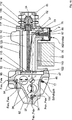
4 eine Darstellung einer Laserkanone zu der erfindungsgemäßen Laserstrahlungsquelle mit einer Mehrfachanordnung von Fiberlasern, 4 a representation of a laser gun to the laser radiation source according to the invention with a multiple array of fiber lasers,
4a eine perspektivische Darstellung zu der 4, 4a a perspective view of the 4 .
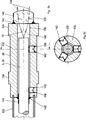
4b eine Variante zur 4, 4b a variant to 4 .
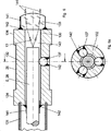
4c eine weitere Variante zu 4 und 4b, 4c another variant too 4 and 4b .
5 ein Beispiel für ein nicht zur Erfindung gehörendes Abschlußstück (Terminator) für die Auskopplung der Strahlung aus einer Faser bzw. der Fiber eines Fiberlasers, 5 an example of a not belonging to the invention terminator for the extraction of radiation from a fiber or the fiber of a fiber laser,
5a ein Beispiel einer Mehrfachanordnung für mehrere Abschlußstücke, 5a an example of a multiple arrangement for several end pieces,
5b ein nicht zur Erfindung gehörendes Beispiel für ein Abschlußstück mit Justierschrauben, 5b a not belonging to the invention example of a terminator with adjusting screws,
5c einen Querschnitt durch das Abschlußstück gemäß 5b im Bereich der Justierschrauben, 5c a cross section through the end piece according to 5b in the area of adjusting screws,
6 ein Beispiel eines nicht zur Erfindung gehörendes Abschlußstücks mit kugelförmigen Justierelementen, 6 an example of a not belonging to the invention end piece with spherical adjusting elements,
6a einen Querschnitt durch das Abschlußstück gemäß 6 im Bereich der kugelförmigen Justierelemente, 6a a cross section through the end piece according to 6 in the area of the spherical adjusting elements,
7 ein Beispiel einer Ausführung eines nicht zur Erfindung gehörenden Abschlußstücks mit einer konischen Passung zum Einsatz in eine Fassung, 7 an example of an embodiment of a not belonging to the invention end piece with a conical fit for use in a socket,
8 ein Beispiel für eine Mehrfachfassung für mehrere nicht zur Erfindung gehörende Abschlußstücke, 8th an example of a multiple socket for several non-invention end pieces,
8a die rückwärtige Befestigung der Abschlußstücke gemäß 8, 8a the rear attachment of the end pieces according to 8th .
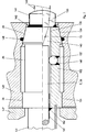
9 ein Beispiel für eine nicht zur Erfindung gehörende Ausführungsform mit quadratischem Querschnitt, 9 an example of a not belonging to the invention embodiment with square cross section,
9a ein Querschnitt durch das nicht zur Erfindung gehörende Abschlußstück gemäß 9, 9a a cross section through the not belonging to the invention end piece according to 9 .
10 ein Beispiel für ein nicht zur Erfindung gehörendes Abschlußstück mit rechteckförmigem Querschnitt und einer trapezförmigen Draufsicht, 10 an example of a not belonging to invention end piece with rectangular cross-section and a trapezoidal plan view,
10a einen Längsschnitt durch das Abschlußstück gemäß 10, 10a a longitudinal section through the end piece according to 10 .
10b einen Querschnitt durch das Abschlußstück gemäß 10, 10b a cross section through the end piece according to 10 .
11 ein Beispiel für ein nicht zur Erfindung gehörendes Abschlußstück mit trapezförmigem Querschnitt, 11 an example of a not belonging to the invention end piece with trapezoidal cross section,
11a ein Beispiel für ein nicht zur Erfindung gehörendes Abschlußstück mit dreieckigem Querschnitt, 11a an example of a not belonging to the invention end piece with triangular cross section,
12 ein Beispiel für ein nicht zur Erfindung gehörendes Abschlußstück mit wabenförmigem Querschnitt, 12 an example of a not belonging to the invention end piece with honeycomb cross section,
13 eine modulare Ausführung der Fiber des Fiberlasers gemäß 1, 13 a modular design of the fiber of the fiber laser according to 1 .
14 ein nicht zur Erfindung gehörendes Beispiel für die Einkopplung der Pumpenergie in die Fiber des Fiberlasers gemäß 13, 14 a not belonging to the invention example of the coupling of the pumping energy into the fiber of the fiber laser according to 13 .
15 ein nicht zur Erfindung gehörendes Beispiel für einen Fiberlaser mit zwei Ausgängen, 15 a non-invention example of a fiber laser with two outputs,
16 ein nicht zur Erfindung gehörendes Beispiel zum Zusammenführen zweier Fiberlaser, 16 a not belonging to the invention example for merging two fiber lasers,
17 eine schematische Darstellung des Strahlengangs durch einen akustooptischen Ablenker bzw. Modulator, 17 a schematic representation of the beam path through an acousto-optical deflector or modulator,
18 das Ausblenden von nicht gewünschten Teilstrahlen eines akustooptischen Ablenkers bzw. Modulators, 18 hiding unwanted partial beams of an acousto-optic deflector or modulator,
18a eine Anordnung mit einem elektrooptischen Modulator, 18a an arrangement with an electro-optical modulator,
19 eine Draufsicht auf einen vierkanaligen akustooptischen Modulator, 19 a top view of a four-channel acousto-optic modulator,
19a einen Schnitt durch den Modulator nach 19, 19a a section through the modulator after 19 .
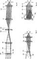
20 einen prinzipiellen Strahlengang für eine Draufsicht zu 4, 20 a basic beam path for a top view 4 .
21 einen prinzipiellen Strahlengang für eine Draufsicht zu 4b, 21 a basic beam path for a top view 4b .
22 einen prinzipiellen Strahlengang für eine Draufsicht zu 4c, 22 a basic beam path for a top view 4c .
23 einen Strahlengang für nicht zur Erfindung gehörende Abschlußstücke, die unter einem Winkel zueinander angeordnet sind, 23 a beam path for non-inventive end pieces, which are arranged at an angle to each other,
24 eine nicht zur Erfindung gehörende Variante der 23, die einen mehrkanaligen akustooptischen Modulator enthält, 24 a not belonging to the invention variant of 23 containing a multi-channel acousto-optic modulator,
24a eine nicht zur Erfindung gehörende Variante zu 24, 24a a variant not belonging to the invention 24 .
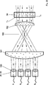
25 eine Zwischenabbildung zur Anpassung der Fiberlaser bzw. ihrer nicht zur Erfindung gehörenden Abschlußstücke beispielsweise an den Modulator, 25 an intermediate image for adapting the fiber lasers or their non-invention end pieces, for example, to the modulator,
26 das nicht zur Erfindung gehörende Zusammenführen von zweimal vier Spuren der Strahlenbündel aus Abschlußstücken mittels einer Streifenspiegelanordnung, 26 the not belonging to the invention merging two times four tracks of bundles of rays from end pieces by means of a streak mirror assembly,
26a eine Draufsicht zur 26, 26a a plan view to 26 .
27 eine Ansicht eines nicht zur Erfindung gehörenden Streifenspiegels, 27 a view of a not belonging to the invention strip mirror,
27a eine Schnittzeichnung durch den Streifenspiegel nach 27, 27a a sectional drawing through the streak mirror after 27 .
27b ein weiteres nicht zur Erfindung gehörendes Beispiel für einen Streifenspiegel, 27b another example not belonging to the invention for a strip mirror,
28 das nicht zur Erfindung gehörende Zusammenführen von zweimal vier Spuren der Strahlenbündel aus Abschlußstücken mittels eines wellenlängenabhängigen Spiegels, 28 the not belonging to the invention merging of two times four tracks of the beams of terminators by means of a wavelength-dependent mirror,
28a eine Draufsicht zur 28, 28a a plan view to 28 .
29 eine nicht zur Erfindung gehörende Anordnung von mehreren Abschlußstücken in mehreren Spuren und in mehreren Ebenen, 29 a non-invention arrangement of multiple terminators in multiple tracks and in multiple levels,
30 eine nicht zur Erfindung gehörende Anordnung von mehreren Abschlußstücken in einem Bündel, 30 a non-invention arrangement of several end pieces in a bundle,
31 eine Schnittzeichnung durch die Strahlenbündel aus den Abschlußstücken der Fiberlaser F1 bis F3 gemäß 29 oder 30, 31 a sectional drawing through the beams from the terminators of the fiber lasers F1 to F3 according to 29 or 30 .
32 eine nicht zur Erfindung gehörende Anordnung mit mehreren Abschlußstücken in mehreren Spuren und mehreren Ebenen mit einer Zylinderoptik zur Anpassung beispielsweise an den Modulator, 32 a not belonging to the invention arrangement with several terminators in multiple tracks and multiple levels with a cylinder optics for adaptation, for example, to the modulator,
33 eine Variante der 32, 33 a variant of 32 .
34 ein Mundstück für die Laserkanone mit Anschlüssen für Druckluft und zur Absaugung des vom Strahl freigesetzten Materials, 34 a mouthpiece for the laser cannon with connections for compressed air and for the extraction of the material released by the jet,
35 eine Verdrehung der Laserkanone zur Einstellung des Spurabstandes, 35 a rotation of the laser gun to adjust the track spacing,
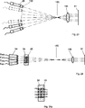
36 eine Darstellung zur Erzeugung von vier Spuren mit einem akustooptischen Mehrfachablenker bzw. -modulator, 36 a representation for the generation of four tracks with an acousto-optical Mehrfachablenker or modulator,
36a eine räumliche Darstellung eines akustooptischen Mehrfachablenkers bzw. -modulators, 36a a spatial representation of an acousto-optic Mehrfachablenkers or modulator,
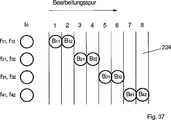
37 eine Darstellung zur Erzeugung von Mehrfachspuren mit Hilfe eines akustooptischen Mehrfachablenkers bzw. -modulators, 37 a representation for the generation of multiple tracks by means of an acousto-optical Mehrfachablenkers or modulator,
38 eine vorteilhafte nicht zur Erfindung gehörende Anordnung zur Vermeidung von Rückreflexionen in die Laser, 38 an advantageous arrangement not belonging to the invention for avoiding back reflections into the lasers,
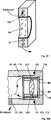
39 eine nicht zur Erfindung gehörende Linse, die von einem Kühlmittel umflossen wird, 39 a non-invention lens, which is surrounded by a coolant,
39a einen Schnitt durch eine Fassung für die Objektivlinse, 39a a section through a socket for the objective lens,
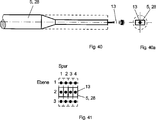
40 einen nicht zur Erfindung gehörenden Fiberlaser oder eine Faser, die an ihrem Austrittsende in ihrem Querschnitt deutlich reduziert worden sind, 40 a fiber laser not belonging to the invention or a fiber which have been significantly reduced at its exit end in its cross-section,
40a eine Draufsicht auf das Ende des Fiberlasers oder der Faser nach 40, 40a a plan view of the end of the fiber laser or the fiber after 40 .
41 eine nicht zur Erfindung gehörende Anordnung von Fiberlasern oder Fasern gemäß 40 in mehreren Spuren und Ebenen, 41 a not belonging to the invention arrangement of fiber lasers or fibers according to 40 in several tracks and levels,
42 eine weitere nicht zur Erfindung gehörende Ausführungsform der Laserstrahlungsquelle, 42 a further embodiment of the laser radiation source not belonging to the invention,
42a eine weiterführende nicht zur Erfindung gehörende Ausführungsform nach 42, 42a a further not belonging to the invention embodiment 42 .
42b ein Schnittzeichnung der 42a, 42b a sectional drawing of 42a .
42c eine Darstellung eines nicht zur Erfindung gehörenden Roboters, 42c an illustration of a robot not belonging to the invention,
43 eine Flachbett-Anordnung mit der erfindungsgemäßen Laserstrahlungsquelle, 43 a flat bed arrangement with the laser radiation source according to the invention,
43a eine Ergänzung zu 43, 43a an addition to 43 .
43b eine Schnittzeichnung durch eine Anordnung zur Entfernung des bei der Bearbeitung freigesetzten Materials, 43b a sectional view through an arrangement for removing the material released during processing,
44 eine Hohlbett-Anordnung mit der erfindungsgemäßen Laserstrahlungsquelle und 44 a hollow bed arrangement with the laser radiation source according to the invention and
44a eine Ergänzung zu 44. 44a an addition to 44 ,
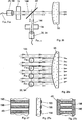
In 1 ist eine Laserstrahlungsquelle 1 dargestellt, die aus mehreren, erfindungsgemäß vorzugsweise als Module ausgeführten, diodengepumpten Fiberlasern (Faserlaser) (2) besteht, die von einer vorzugsweise modularen Versorgung 32 mit elektrischer Energie beaufschlagt werden, die teilweise in Laserstrahlung umgesetzt wird. Weiterhin ist eine Steuerung 33 vorgesehen, über die die Modulation der Strahlung vorgenommen wird und die für das Zusammenwirken der Laserstrahlungsquelle mit ihrer Peripherie sorgt. Die Ausgangsstrahlen der Laser treten am Strahlungseingang 9 in eine optische Einheit 8 ein und am Strahlungsausgang 10 aus der optischen Einheit aus. Die Aufgabe der optischen Einheit 8 ist die Formung der Laserstrahlung zu Bearbeitungsflecken 24 auf einer Bearbeitungsfläche 81.In 1 is a laser radiation source 1 shown, which consists of several, preferably embodied as modules according to the invention, diode-pumped fiber lasers (fiber lasers) ( 2 ) consists of a preferably modular supply 32 be subjected to electrical energy, which is partially converted into laser radiation. Furthermore, there is a controller 33 provided, via which the modulation of the radiation is made and which ensures the interaction of the laser radiation source with its periphery. The output beams of the lasers appear at the radiation input 9 in an optical unit 8th on and at the radiation output 10 out of the optical unit. The task of the optical unit 8th is the shaping of the laser radiation to processing spots 24 on a working surface 81 ,
In den 2 und 2a wird der prinzipielle Aufbau einer Fiberlaser-(auch Faserlaser genannt)Anordnung 2 gezeigt. In 2 wird die Energie einer Pumpquelle wie z. B. einer Laserdiode, hier Pumpquelle 18 genannt, über eine Einkoppeloptik 3 zu einem geeigneten Pumpfleck 4 geformt und in die Laserfiber 5 eingekoppelt. Solche Pumpquellen sind z. B. in der DE 196 03 704 A1 beschrieben. Typische Pumpquerschnitte der Laserfibern liegen etwa zwischen 100 μm und 600 μm bei einer numerischen Apertur von etwa 0,4. Die Laserfiber 5 ist auf der Einkoppelseite 6 mit einem Einkoppelspiegel 7 versehen, der die Pumpstrahlung ungehindert durchläßt, für die Laserstrahlung aber eine 100%ige Reflexion aufweist. Der Einkoppelspiegel 7 kann mit einer geeigneten Halterung oder durch Kleben an dem Faserende befestigt sein, er kann aber auch durch direktes Aufdampfen einer geeigneten Schicht, wie sie bei Einkoppelspiegeln für Laser verwendet wird, auf das Faserende realisiert werden. Auf der Auskoppelseite 11 der Laserfiber 5 ist ein für die Laserstrahlung teildurchlässiger Auskoppelspiegel 12 angebracht, durch den die Laserstrahlung 13 ausgekoppelt wird. In vorteilhafter Weise weist der Auskoppelspiegel für die Pumpstrahlung eine 100%ige Reflexion auf. Hierdurch wird die restliche Pumpstrahlung wieder zurück in die Lichtleitfaser reflektiert, was vorteilhaft ist, da die Pumpenergie besser ausgenutzt wird und außerdem nicht bei der Anwendung der Laserstrahlung stört. Der Auskoppelspiegel kann wie beim Einkoppelspiegel, ebenfalls durch Aufdampfen hergestellt werden.In the 2 and 2a is the basic structure of a fiber laser (also called fiber laser) arrangement 2 shown. In 2 the energy of a pump source such. B. a laser diode, here pump source 18 called, via a Einkoppeloptik 3 to a suitable pump leak 4 shaped and into the laser fiber 5 coupled. Such pump sources are z. B. in the DE 196 03 704 A1 described. Typical pump cross-sections of the laser fibers are approximately between 100 .mu.m and 600 .mu.m with a numerical aperture of about 0.4. The laser fiber 5 is on the feed-in side 6 with a coupling mirror 7 provided that passes the pump radiation unhindered, but for the laser radiation has a 100% reflection. The coupling mirror 7 can be attached to the fiber end with a suitable support or by gluing, but it can also be realized by direct vapor deposition of a suitable layer, as used in coupling mirrors for lasers, on the fiber end. On the decoupling side 11 the laser fiber 5 is a partially transparent for the laser radiation Auskoppelspiegel 12 attached by the laser radiation 13 is decoupled. The output mirror for the pump radiation advantageously has a 100% reflection. As a result, the remaining pump radiation is reflected back into the optical fiber, which is advantageous because the pump energy is better utilized and also does not interfere with the application of laser radiation. The output mirror can also be produced by vapor deposition as with the coupling mirror.
In 2a ist der Einkoppelvorgang der Pumpstrahlung in den Pumpquerschnitt 14 der Laserfiber 5 näher dargestellt. Die Energie im Pumpfleck 4 regt auf ihrem Weg durch die Faser die Laserstrahlung im Kern 15 der Laserfiber 5 an. Der Pumpkern 16 ist von einem Mantel 17 umgeben. Der etwa 5 μm bis 10 μm starke Kern der Laserfiber ist vorwiegend mit Seltenen Erden dotiert.In 2a is the coupling process of the pump radiation in the pump cross section 14 the laser fiber 5 shown in more detail. The energy in the pump leak 4 stimulates the laser radiation in its core on its way through the fiber 15 the laser fiber 5 at. The pump core 16 is from a coat 17 surround. The approximately 5 μm to 10 μm thick core of the laser fiber is predominantly doped with rare earths.
Der relativ große Pumpquerschnitt 14 vereinfacht das Einkoppeln der Pumpenergie und ermöglicht den Einsatz einer einfach lösbaren Verbindung zwischen Pumpquelle und Laserfiber, wie in den 13 und 14 gezeigt wird. Dabei kann das pumpquellenseitige Abschlußstück der Laserfiber in vorteilhafter Weise baugleich sein mit dem Abschlußstück auf der Auskoppelseite, es muß es aber nicht. Eine präzise Steckverbindung zwischen Pumpquelle und Laserfiber bietet erhebliche Vorteile bei der Fertigung der Fiberlaser und im Servicefall. Die Laserfiber kann aber auch fest mit der Pumpquelle zu einem Lasermodul verbunden sein. Infolge des gezielt hergestellten, sehr geringen Faserkerndurchmessers liefert der Fiberlaser am Austritt eine praktisch beugungsbegrenzte Laserstrahlung 13.The relatively large pump cross-section 14 simplifies the coupling of the pump energy and allows the use of an easily detachable connection between pump source and laser fiber, as in the 13 and 14 will be shown. In this case, the pump-source-side terminator of the laser fiber in an advantageous manner be identical to the terminator on the coupling-out, but it does not have to. A precise connection between pump source and laser fiber offers considerable advantages in the production of fiber lasers and in servicing. The laser fiber can also be firmly connected to the pump source to a laser module. As a result of the deliberately manufactured, very small fiber core diameter, the fiber laser at the outlet delivers a laser beam that is virtually diffraction-limited 13 ,
Wie unter 3, 15 und 16 näher beschrieben, kann man an den aktiven Ausgang von Fiberlasern auch passive Fasern 28 ankoppeln.As under 3 . 15 and 16 described in more detail, you can also passive fibers to the active output of fiber lasers 28 Docking.
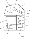
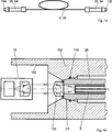
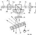
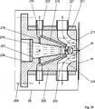
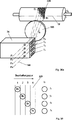
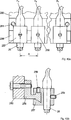
In 3 ist ein Querschnitt durch eine erfindungsgemäße Ausführung einer Anordnung zur Materialbearbeitung mit der erfindungsgemäßen Laserstrahlungsquelle dargestellt. In einem Gehäuse 21 ist eine Trommel 22 drehbar gelagert und wird von einem nicht dargestellten Antrieb in Rotation versetzt. Auf einem ebenfalls nicht dargestellten Prisma befindet sich eine Laserkanone 23, die in axialer Richtung mittels eines nicht dargestellten Schlittens an der Trommel entlang geführt wird.In 3 is a cross section through an inventive embodiment of an arrangement for material processing with the laser radiation source according to the invention shown. In a housing 21 is a drum 22 rotatably mounted and is rotated by a drive, not shown in rotation. On a likewise not shown prism is a laser cannon 23 , which is guided in the axial direction by means of a carriage, not shown, on the drum along.
Die aus der Laserkanone 23 austretende Laserstrahlung trifft am Bearbeitungsort im Bearbeitungsfleck 24 auf die Oberfläche der Trommel. Es kann sowohl die Oberfläche der Trommel bearbeitet werden, als auch ein auf die Trommeloberfläche aufgespanntes Material. In die Laserkanone 23 werden die Fiberlaser, deren Laserfibern 5 jeweils zu einer luftdurchströmten Spule 25 aufgewickelt sind, mittels der Abschlußstücke 26, 94 eingespeist. Es können aber auch an die Fiberlaser passive Singlemodefasern oder andere passive Lichtleitfasern, kurz Fasern 28 genannt, angeschweißt oder auf eine andere Weise angekoppelt sein, bevor die Abschlußstücke 26, 94 angebracht werden, wie in den 15 und 16 beschrieben wird. Die Pumpquellen 18 der Fiberlaser sind auf einem Kühlkörper 27 angebracht, der die Verlustwärme über ein Kühlsystem 31 ableitet. Bei dem Kühlsystem 31 kann es sich um einen Wärmeaustauscher handeln, der die Verlustwärme an die umgebende Luft abgibt, es kann sich aber auch um ein Kühlaggregat handeln. Auch die Laserkanone 23 kann an das Kühlsystem angeschlossen sein, was aber nicht dargestellt ist. Auf dem Kühlkörper befindet sich vorzugsweise die Treiberelektronik für die der Pumpquellen 18, die zu der nicht weiter dargestellten Versorgung 32 gehören. Eine Maschinensteuerung ist für die Antriebe vorgesehen, aber in 3 nicht dargestellt. Der Aufbau der Pumpquellen, Fiberlaser und zugehöriger Leistungselektronik ist vorzugsweise modular ausgeführt, so daß zu den einzelnen Fiberlasern entsprechende Pumpquellen und getrennte oder gruppenweise zusammengefaßte Leistungsmodule der Treiberelektronik gehören, die über ein Bussystem miteinander verbunden sein können. Wie in 13 und 14 näher erläutert, jedoch nicht zur Erfindung gehörend, können die Laserfibern 5 und die Pumpquellen 18 über eine lösbare Verbindung miteinander verbunden sein. Es ist auch möglich, jedoch nicht zur Erfindung gehörend, einen geringen Anteil der Pumpstrahlung beispielsweise durch eine geringfügige Verletzung des Mantels 14 aus der Laserfiber 5 auszukoppeln und vorzugsweise über eine Lichtleitfaser auf eine Meßzelle zu leiten, um daraus ein Signal zu bereiten, das zur Steuerung bzw. Regelung der Pumpstrahlung verwendet werden kann.The from the laser cannon 23 Exiting laser radiation hits the machining spot in the processing spot 24 on the surface of the drum. It can be edited both the surface of the drum, as well as a spanned on the drum surface material. In the laser cannon 23 become the fiber lasers, their laser fibers 5 each to one air-flowed coil 25 are wound up, by means of the terminators 26 . 94 fed. But it can also be to the fiber laser passive single-mode fibers or other passive optical fibers, short fibers 28 be welded, welded or otherwise coupled before the end pieces 26 . 94 be attached, as in the 15 and 16 is described. The pump sources 18 the fiber lasers are on a heat sink 27 attached, the heat loss through a cooling system 31 derives. In the cooling system 31 it may be a heat exchanger that releases the heat loss to the surrounding air, but it may also be a cooling unit. Also the laser cannon 23 may be connected to the cooling system, but this is not shown. On the heat sink is preferably the driver electronics for the pump sources 18 leading to the supply not shown 32 belong. A machine control is provided for the drives, but in 3 not shown. The structure of the pump sources, fiber lasers and associated power electronics is preferably modular, so that corresponding to the individual fiber lasers corresponding pump sources and separate or group-wise combined power modules of the driver electronics, which may be connected to each other via a bus system. As in 13 and 14 explained in more detail, but not belonging to the invention, the laser fibers 5 and the pump sources 18 be connected to each other via a detachable connection. It is also possible, but not belonging to the invention, a small proportion of the pump radiation, for example, by a slight violation of the jacket 14 from the laser fiber 5 decouple and preferably to conduct over an optical fiber to a measuring cell in order to prepare a signal that can be used to control or regulating the pump radiation.
In der Steuerung 33 werden die Modulationssignale für die Laserstrahlung erzeugt und für das Zusammenwirken der Laserstrahlungsquelle mit der Maschinensteuerung und mit der Versorgung 32 sowie für den Ablauf der Kalibriervorgänge sowie der Steuer- und Regelvorgänge gesorgt. Eine nicht dargestellte Sicherheitsschaltung schaltet beispielsweise die Pumpquellen dauerhaft ab, wenn Gefahr droht.In the control 33 The modulation signals are generated for the laser radiation and for the interaction of the laser radiation source with the machine control and with the supply 32 as well as for the course of the calibration procedures as well as the control and regulating operations. A safety circuit, not shown, permanently switches off, for example, the pumping sources when danger threatens.
Es ist zwar in 3 eine horizontal gelagerte Trommel dargestellt, da aber die Laserstrahlungsquelle in ihrer Lage völlig richtungsunempfindlich und vom Aufbau her sehr kompakt ist und zudem die Laserfibern 5 der Fiberlasers oder an die Laserfiber angekoppelte Fasern 28 beliebig verlegt werden können, kann die Trommel in jeder beliebigen Lage angeordnet sein, zum Beispiel kann die Achse der Trommel auch vertikal oder gegen die Senkrechte geneigt gelagert sein, was eine besonders kleine Standfläche ergibt. Außerdem ist hierdurch der Betrieb mehrer Anordnungen oder eine Anlage mit mehren Trommeln auf der gleichen Standfläche möglich, wie sie eine Anordnung mit horizontal gelagerter Trommel benötigen würde. Dadurch können die Druckformen schneller hergestellt werden, insbesondere können alle Druckformen für einen Farbsatz in einem einzigen parallelen Durchgang erstellt werden, was besonders bezüglich der Gleichförmigkeit des Endresultats von Vorteil ist. Auch läßt sich bei einer auf kleiner Standfläche aufgebauten Anlage besser eine automatische Beschickung mit Druckformen zur Bebilderung realisieren, als bei einer räumlich größeren Anlage. Es können auch mehrere Laserstrahlungsquellen oder mehrere Laserkanonen auf die gleiche Druckform gerichtet werden, um deren Erstellung zu beschleunigen. Dabei ist ein Vorteil der mehrspurigen Anordnung mit den sehr feinen und präzisen Spuren, daß sich eventuelle Nahtstellen deutlich weniger störend bemerkbar werden, als wenn mit gröberen Spuren aufgezeichnet wird. Weiterhin kann, wie unter 37 beschrieben, die Lage der Spuren präzise nachgestellt werden, so daß Restfehler deutlich kleiner werden als eine einer Spurbreite.It is indeed in 3 a horizontally mounted drum shown, but since the laser radiation source is completely directionally insensitive and structurally very compact in their position and also the laser fibers 5 fiber lasers or fibers coupled to the laser fibers 28 can be placed arbitrarily, the drum can be arranged in any position, for example, the axis of the drum can also be mounted vertically or inclined to the vertical, resulting in a particularly small footprint. In addition, this allows the operation of several arrangements or a system with several drums on the same footprint, as they would require an arrangement with horizontally mounted drum. As a result, the printing forms can be produced faster, in particular all printing forms for a color set can be created in a single parallel passage, which is particularly advantageous with respect to the uniformity of the final result. Also can be realized in a built on a small footprint plant better an automatic feed of printing forms for imaging, as in a spatially larger plant. It is also possible to direct a plurality of laser radiation sources or a plurality of laser cannons to the same printing form in order to accelerate their production. It is an advantage of the multi-track arrangement with the very fine and precise tracks that any seams are significantly less disturbing than when recorded with coarser tracks. Furthermore, as under 37 described, the position of the tracks are adjusted precisely so that residual errors are significantly smaller than a track width.
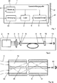
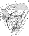
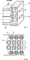
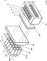
In 4 ist ein Schnitt durch ein Anwendungsbeispiel für eine Laserkanone mit sechzehn Fiberlasern, die über Abschlußstücke 26 angekoppelt sind, und mit einer Modulationseinheit, bestehend aus zwei mehrkanaligen akustooptischen Modulatoren 34 gezeigt. Die Laserkanone ist eine mehrteilige Aufnahme für die optische Einheit und enthält Fassungen 29 (4a) mit Paßflächen für die Passungen der Abschlußstücke 26, Mittel zum Zusammenführen der einzelnen Laserstrahlen, die Modulationseinheit, eine Übertragungseinheit zum Übertragen der Laserstrahlung, die einen Bearbeitungseffekt hervorrufen soll, auf die Bearbeitungsfläche und eine Anordnung zum Unschädlichmachen der Laserstrahlung, die keinen Bearbeitungseffekt hervorrufen soll. An der Laserkanone kann eine Anordnung zum Entfernen des von der Bearbeitungsfläche abgetragenen Materials angeordnet sein, die aber auch auf andere Weise in der Nähe der Bearbeitungsfläche angeordnet sein kann.In 4 is a section through an application example of a laser cannon with sixteen fiber lasers, the over terminators 26 coupled with a modulation unit consisting of two multi-channel acousto-optic modulators 34 shown. The laser cannon is a multi-part optical unit holder and contains sockets 29 ( 4a ) with mating surfaces for the fits of the terminators 26 Means for merging the individual laser beams, the modulation unit, a transmission unit for transmitting the laser radiation, which is to cause a processing effect, on the processing surface and an arrangement for rendering the laser radiation harmless, which is not intended to produce a processing effect. An arrangement for removing the material removed from the processing surface may be arranged on the laser gun, but it may also be arranged in another way in the vicinity of the processing surface.
4a ist eine perspektivische Darstellung zu 4. 4a is a perspective view too 4 ,
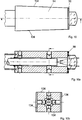
In 4b ist eine Variante zu 4 gezeigt, bei der die Strahlenbündel der einzelnen Fiberlaser nicht wie in 4 parallel verlaufen, sondern unter einem Winkel zueinander, was aber aus der Schnittzeichnung in 4b nicht ersichtlich ist und deshalb in den 21, 22 und 24 näher erläuert wird.In 4b is a variant too 4 shown in which the beams of each fiber laser not as in 4 parallel, but at an angle to each other, but what the sectional drawing in 4b is not apparent and therefore in the 21 . 22 and 24 is explained in more detail.
In 4c ist eine Variante zu 4b gezeigt, die infolge einer anders ausgeführten Übertragungseinheit eine vorteilhafte, wesentlich kompaktere Bauform ermöglicht.In 4c is a variant too 4b shown, which allows an advantageous, much more compact design due to a differently executed transmission unit.
Es wird zunächst die 4 unter Zuhilfenahme der 4a ausführlich erläutert. Diese Erläuterungen gelten sinngemäß auch für die 4b und 4c. It will be the first 4 with the help of the 4a explained in detail. These explanations apply mutatis mutandis to the 4b and 4c ,
In einem Gehäuse 35 sind am Strahlungseintritt 9 (1) jeweils 4 Fiberlaser FHD1 bis FHD4, FVD1 bis FVD4, FHR1 bis FHR4, FVR1 bis FVR4 über die Abschlußstücke 26 mittels der Fassungen 29 in jeweils vier Spuren zu je einem Strahlenpaket nebeneinander in einer Ebene angeordnet. Die Ausführungsform der in 4 verwendeten, jedoch nicht zur Erfindung gehörenden Abschlußstücke 26 ist in 9 näher beschrieben. Die Abschlußstücke sollen vorzugsweise gasdicht in das Gehäuse 35 eingesetzt werden, wozu Dichtungen 36 (4a) verwendet werden können. Es können anstelle der in den 4 und 4a dargestellten Abschlußstücke auch anders geformte Abschlußstücke verwendet werden, wie sie in den 5, 5a, 5b, 5c, 6, 6a, 7, 9, 9a, 10, 10a, 10b, 11, 11a, und 12 beschrieben sind, wenn entsprechende Fassungen 29 im Gehäuse 35 vorgesehen sind. Es können aber auch wie unter 3 beschrieben, Singlemodefasern oder andere Fasern 28 an die Fiberlaser angebracht sein, bevor die Abschlußstücke 26 angebracht werden. Es kann aber auch eine nicht zur Erfindung gehörende Anordnung der Laserfibern 5 oder Fasern 28 gemäß 40, 40a und 41 Anwendung finden. Die Fiberlaser FHD1 bis FHD4 bzw. FVR1 bis FVR4 sollen beispielsweise eine andere Wellenlänge haben, als die Fiberlaser FVD1 bis FVD4 bzw. FHR1 bis FHR4. Zum Beispiel sollen FHD1 bis FHD4 und FVR1 bis FVR4 eine Wellenlänge von 1100 nm haben, während FVD1 bis FVD4 bzw. FHR1 bis FHR4 eine Wellenlänge von 1060 nm haben sollen, was durch eine entsprechend Dotierung des laseraktiven Kernmaterials der Laserfiber 5 erreicht werden kann. Es können aber auch alle Fiberlaser unterschiedliche Wellenlängen aufweisen, wenn sie entsprechend zusammengestellt werden.In a housing 35 are at the radiation entrance 9 ( 1 ) 4 fiber lasers F HD1 to F HD4 , F VD1 to F VD4 , F HR1 to F HR4 , F VR1 to F VR4 via the terminators 26 by means of the versions 29 arranged in each case in four tracks, each one beam packet side by side in a plane. The embodiment of in 4 used, but not part of the invention terminators 26 is in 9 described in more detail. The terminators are preferably gas-tight in the housing 35 be used, including seals 36 ( 4a ) can be used. It can instead of in the 4 and 4a shown terminators also differently shaped terminators are used, as in the 5 . 5a . 5b . 5c . 6 . 6a . 7 . 9 . 9a . 10 . 10a . 10b . 11 . 11a , and 12 are described, if appropriate versions 29 in the case 35 are provided. But it can also be like under 3 described single-mode fibers or other fibers 28 be attached to the fiber laser before the terminators 26 be attached. But it may also be a non-invention belonging to the arrangement of laser fibers 5 or fibers 28 according to 40 . 40a and 41 Find application. The fiber lasers F HD1 to F HD4 or F VR1 to F VR4 , for example, should have a different wavelength than the fiber lasers F VD1 to F VD4 or F HR1 to F HR4 . For example, F HD1 to F HD4 and F VR1 to F VR4 should have a wavelength of 1100 nm, while F VD1 to F VD4 or F HR1 to F HR4 should have a wavelength of 1060 nm, resulting in a corresponding doping of the laser-active core material the laser fiber 5 can be achieved. However, all fiber lasers can also have different wavelengths if they are combined accordingly.
Wie in 28 und 28a näher erläutert, aber nicht zur Erfindung gehörend, werden über wellenlängenabhängige Spiegel 37 als Mittel zum Zusammenführen die Strahlenpakete der Fiberlaser FHD1 bis FHD4 mit denen der Fiberlaser FVD1 bis FVD4 sowie die Strahlenpakete der Fiberlaser FVR1 bis FVR4 mit denen der Fiberlaser FHR1 bis FHR4 zu jeweils einem Strahlenpaket FD1 bis FD4 sowie FR1 bis FR4 (4a) vereinigt. Es gibt auch andere Möglichkeiten, die Wellenlänge der Fiberlaser zu beeinflussen, zum Beispiel können im Bereich der Laserfiber zwischen Einkoppelspiegel 7 und Auskoppelspiegel 12 wellenlängenselektierende Elemente wie Brewsterplatten, Beugungsgitter oder Schmalbandfilter eingebracht werden. Auch ist es möglich, mindestens einen der beiden Laserspiegel 7 oder 12 mit einer solchen Spiegelschicht zu versehen, die nur für die gewünschte Wellenlänge ausreichend hoch reflektierend ist. Die Ausführung der Strahlzusammenführung ist aber nicht auf die Verwendung von Fiberlasern unterschiedlicher Wellenlänge beschränkt. Neben Fiberlasern, die keine Vorzugsrichtung in der Polarisation der abgegebenen Laserstrahlung haben, können auch Fiberlaser verwendet werden, die polarisierte Laserstrahlung abgeben, was jedoch nicht Gegenstand der Erfindung ist. Wenn man den wellenlängenabhängigen Spiegel durch einen solchen ersetzt, der so polarisationsabhängig ist, daß er eine Polarisationsrichtung durchläßt, während er die andere Polarisationsrichtung reflektiert, müssen nur zwei unterschiedlich polarisierte Lasertypen verwendet werden, um beide mittels des polarisationsabhängigen Spiegels zu vereinigen. In diesem Fall ist die Verwendung des nicht zur Erfindung gehörenden Abschlußstückes 26 nach 9 mit quadratischem Querschnitt besonders geeignet, da man durch Wenden des Abschlußstücks um 90° vor der Montage in das Gehäuse 35 jeweils die eine oder die andere Polarisationsrichtung mit dem gleichen Fiberlaser erzeugen kann.As in 28 and 28a explained in more detail, but not belonging to the invention are about wavelength-dependent mirror 37 as means for merging the beam packets of the fiber lasers F HD1 to F HD4 with those of the fiber lasers F VD1 to F VD4 and the beam packets of the fiber lasers F VR1 to F VR4 with those of the fiber lasers F HR1 to F HR4 to a respective radiation packet F D1 to F D4 and F R1 to F R4 ( 4a ) united. There are other ways to influence the wavelength of the fiber laser, for example, in the range of laser fiber between Einkoppelspiegel 7 and Auskoppelspiegel 12 wavelength-selecting elements such as Brewster plates, diffraction gratings or narrow band filters are introduced. It is also possible to have at least one of the two laser mirrors 7 or 12 to be provided with such a mirror layer, which is sufficiently highly reflective only for the desired wavelength. The execution of the beam merge is not limited to the use of fiber lasers of different wavelengths. In addition to fiber lasers, which have no preferred direction in the polarization of the emitted laser radiation, and fiber lasers can be used which emit polarized laser radiation, which is not the subject of the invention. By replacing the wavelength-dependent mirror with one that is polarization-dependent to pass one direction of polarization while reflecting the other direction of polarization, only two differently polarized types of laser need to be used to combine both by means of the polarization-dependent mirror. In this case, the use of the not belonging to the invention end piece 26 to 9 Particularly suitable with square cross-section, as you by turning the end piece by 90 ° before mounting in the housing 35 each can produce one or the other polarization direction with the same fiber laser.
Ein besonderer Vorteil der nicht zur Erfindung gehörenden Zusammenführung mehrerer Laser zu einem einzigen Fleck, nämlich zu jedem der einzelnen Bearbeitungspunkte B1 bis Bn (zum Beispiel B1 bis B4 in 20–22) ist die Erzielung einer höheren Leistungsdichte bei vorgegebener Fleckgröße auf der Bearbeitungsfläche 81.A particular advantage of the not belonging to the invention merging of multiple laser to a single spot, namely to each of the individual processing points B 1 to B n (for example, B 1 to B 4 in 20 - 22 ) is to achieve a higher power density at a given spot size on the processing surface 81 ,
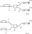
Es kann auch die Laserstrahlung eines einzelnen Fiberlasers auf mehrere Abschlußstücke verteilt werden, was in 15 beschrieben jedoch nicht erfindungsgemäß ist. Dies ist besonders dann von Nutzen, wenn solche Materialien bearbeitet werden sollen, die mit einer geringen Laserleistung auskommen oder wenn die Leistung eines einzelnen Fiberlasers ausreichend hoch ist. In einem solchen Fall ist es denkbar, daß eine Laserkanone 23 zu diesem Zweck nur mit 4 Abschlußstücken z. B. FHD1 bis FHD4 bestückt wird, von denen beispielsweise FHD1 und FHD2 nach 15 von einem Fiberlaser und FHD3 und FHD4 von einem weiteren Fiberlaser gespeist werden. Wenn das in 15 beschriebene Prinzip zweimal angewendet wird, lassen sich alle vier Spuren FHD1 bis FHD4 von einem Fiberlaser speisen, was zu einer sehr kostengünstigen Anordnung führt, zumal weitere Bauteile wie wellenlängenabhängige Spiegel und Streifenspiegel entfallen können und damit eine besonders preiswerte Ausführung der Laserstrahlungsquelle geschaffen werden kann.It can also be the laser radiation of a single fiber laser distributed on several terminators, which in 15 but not described according to the invention. This is particularly useful when processing such materials that can operate with low laser power or when the power of a single fiber laser is sufficiently high. In such a case, it is conceivable that a laser gun 23 For this purpose, only with 4 end pieces z. B. F HD1 to F HD4 is populated, of which, for example, F HD1 and F HD2 after 15 from one fiber laser and F HD3 and F HD4 from another fiber laser. If that is in 15 described principle is applied twice, all four tracks F HD1 to F HD4 can be fed by a fiber laser, resulting in a very cost-effective arrangement, especially since other components such as wavelength-dependent mirrors and streak mirrors can be omitted and thus a particularly inexpensive design of the laser radiation source can be created ,
Weiterhin kann man durch Weglassen von Fiberlasern bzw. Spuren je nach Bedarf die Anschaffungskosten für eine solche Anordnung senken und später je nach Bedarf Fiberlaser nachrüsten. Man kann zum Beispiel mit einem Fiberlaser und einer Spur beginnen. Die fehlenden Abschlußstücke der nicht eingesetzten Fiberlaser werden dazu durch baugleiche Abschlußstücke, die aber keine durchgehende Öffnung und keine Laserfiber enthalten und nur zum Verschluß dienen, ersetzt, um das Gehäuse 35 so zu verschließen, als ob es mit allen Abschlußstücken bestückt wäre.Furthermore, by omitting fiber lasers or tracks as required, it is possible to reduce the initial cost of such an arrangement and later to retrofit fiber lasers as needed. For example, you can start with a fiber laser and a track. The missing terminators of the unused fiber lasers are to the same by identical terminators, but no Through opening and no laser fiber included and only serve for closure, replaced to the housing 35 to shut up as if it were equipped with all final pieces.
Es kann aber auch die Laserstrahlung mehrerer Fiberlaser zusammengefaßt und in ein einzelnes Abschlußstück geleitet werden, was in 16 beschrieben aber nicht erfindungsgemäß ist. Man kann zum Beispiel mit mehreren so zusammengefaßten Fiberlasern und einer Spur arbeiten, wenn man wie beschrieben die fehlenden Abschlußstücke durch baugleiche Abschlußstücke, die aber keine durchgehende Öffnung und keine Laserfiber enthalten und nur zum Verschluß dienen, ersetzt, um das Gehäuse 35 so zu verschließen, als ob es mit allen Abschlußstücken bestückt wäre.But it can also be summarized and the laser radiation of several fiber lasers in a single end piece, which in 16 but not described according to the invention. You can, for example, with several so summarized fiber lasers and a track working if you as described the missing terminators by identical terminators, but no through hole and no laser fiber and serve only for closure, replaced to the housing 35 to shut up as if it were equipped with all final pieces.
Gleich nachdem das Strahlenbündel das jeweilige Abschlußstück verlassen hat, kann über einen Strahlteiler, der aber nicht gezeigt und nicht erfindungsgemäß ist, ein Teil der Laserstrahlung ausgekoppelt und auf eine in den Figuren nicht dargestellte nicht erfindungsgemäße Meßzelle geleitet werden, um daraus eine Meßgröße zu erzeugen, die als Vergleichswert für eine Regelung der Ausgangsleistung jedes Fiberlasers benutzt werden kann. Es kann aber auch bereits vor dem Abschlußstück Laserstrahlung aus der Laserfiber zum Gewinnen einer Meßgröße ausgekoppelt werden, was auch nicht dargestellt und nicht erfindungsgemäß ist.Immediately after the beam has left the respective terminator, can be coupled via a beam splitter, which is not shown and not according to the invention, a portion of the laser radiation and passed to a non-inventive measuring cell not shown in the figures, to generate a measured variable, which can be used as a comparison value for regulating the output power of each fiber laser. However, it is also possible to extract laser radiation from the laser fiber to obtain a measured variable before the terminating piece, which is also not shown and not according to the invention.
Die Anzahl der Ebenen, in denen die Abschlußstücke angeordnet sind, ist nicht auf die beschriebene eine Ebene beschränkt. In den 29, 32, 33 und 41 sind z. B. Anordnungen mit 3 Ebenen angegeben. In 38 ist eine Anordnung mit 2 Ebenen dargestellt.The number of levels in which the terminators are arranged is not limited to the described one level. In the 29 . 32 . 33 and 41 are z. B. Arrangements with 3 levels indicated. In 38 a layout with 2 levels is shown.
Über je einen vierkanaligen akustooptischen Modulator 34, dessen Wirkungsweise und Ausführungsform in den 17, 18, 19 und 19a näher erläutert wird, werden die jeweiligen Strahlenpakete der Fiberlaser moduliert. Durch den akustooptischen Modulator 34, der vom Prinzip her ein Ablenker ist, wird in dem dargestellten Fall die nicht erwünschte Energie aus der ursprünglichen Strahlrichtung I0 in die Srahlrichtung I1 abgelenkt (4a), so daß sie später im Strahlengang einfach abgefangen und unschädlich gemacht werden kann. Die Modulation kann vorzugsweise digital erfolgen, d. h. es wird in den einzelnen Modulatorkanälen nur zwischen zwei Zuständen, nämlich ”EIN” und ”AUS” unterschieden, was besonders einfach zu steuern ist; sie kann aber auch analog erfolgen, indem die Laserleistung in jedem Modulatorkanal auf beliebige Werte eingestellt werden kann. Die Modulation ist nicht darauf beschränkt, daß die Energie aus der Strahlrichtung I0 für die Bearbeitung verwendet wird und die Energie aus der Richtung I1 unschädlich gemacht wird. In den 36, 36a und 37 sind Beispiele angegeben, in denen die abgebeugte Strahlrichtung I1 zur Bearbeitung verwendet wird und die Energie aus der Richtung I0 unschädlich gemacht wird. Auch kann eine geringer Teil der modulierten Strahlungsleistung der einzelnen Modulatorkanäle über einen nicht dargestellten Strahlteiler auf jeweils eine Meßzelle gegeben werden, um eine Meßgröße zu erzeugen, die als Vergleichswert in einem Regelkreis für die genaue Regelung der Laserenergie jeder Spur auf der Bearbeitungsfläche benutzt wird.Each with a four-channel acousto-optic modulator 34 , its mode of action and embodiment in the 17 . 18 . 19 and 19a is explained in more detail, the respective beam packets of the fiber lasers are modulated. Through the acousto-optic modulator 34 , which is a deflector in principle, is deflected in the illustrated case, the unwanted energy from the original beam direction I 0 in the beam direction I 1 ( 4a ), so that they can be easily intercepted later in the beam path and rendered harmless. The modulation can preferably be done digitally, ie it is different in the individual modulator channels only between two states, namely "ON" and "OFF", which is particularly easy to control; but it can also be done analogously by the laser power in each modulator channel can be set to any value. The modulation is not limited to that the energy from the beam direction I 0 is used for the machining and the energy from the direction I 1 is rendered harmless. In the 36 . 36a and 37 Examples are given in which the deflected beam direction I 1 is used for processing and the energy from the direction I 0 is rendered harmless. Also, a small part of the modulated radiation power of the individual modulator channels can be applied to a respective measuring cell via a beam splitter, not shown, in order to generate a measured variable which is used as comparison value in a control circuit for the precise regulation of the laser energy of each track on the processing surface.
Der mehrkanalige akustooptische Modulator 34 ist vorzugsweise auf einem zylindrischen Modulatorgehäuse 41 befestigt, das verdrehbar in einer Öffnung 48 in dem Gehäuse 35 gelagert ist. Nach dem Einjustieren des Modulatorgehäuses auf den erforderlichen Bragg-Winkel αB wird das Modulatorgehäuse mittels einer Verbindung 42 fixiert. Mittels einer Dichtung 43 ist dafür gesorgt, daß jedes Modulatorgehäuse gasdicht zum Gehäuse 35 abschließt. Aus dem Modulatorgehäuse 41 ragt eine speziell präparierte Leiterplatte 171 in den inneren Raum 44 des Gehäuses 35, über die die elektrischen Verbindungen zu den piezoelektrischen Wandlern 45 hergestellt werden. Die vorzugsweise Ausführung der Modulatoren wird in den 19 und 19a ausführlicher beschrieben.The multi-channel acousto-optic modulator 34 is preferably on a cylindrical modulator housing 41 attached, that rotatable in an opening 48 in the case 35 is stored. After the modulator housing has been adjusted to the required Bragg angle α B , the modulator housing is connected by means of a connection 42 fixed. By means of a seal 43 is ensured that each modulator housing gas-tight to the housing 35 concludes. From the modulator housing 41 protrudes a specially prepared circuit board 171 in the inner space 44 of the housing 35 , about which the electrical connections to the piezoelectric transducers 45 getting produced. The preferred embodiment of the modulators is in the 19 and 19a described in more detail.
Nach dem Durchlaufen der akustooptischen Modulatoren werden die Strahlenpakete FD1 bis FD4 und FR1 bis FR4 zu einem Streifenspiegel 46 geführt, der in den 26, 26a, 27, 27a, und 27b näher beschrieben aber nicht erfindungsgemäß ist. Das Strahlenpaket FD1 bis FD4 ist bezüglich des Streifenspiegels 46 so angeordnet, daß es den Streifenspiegel unbehindert durchlaufen kann. Die Laserstrahlenbündel des Strahlenpaketes FR1 bis FR4 sind aber gegenüber dem Strahlenpaket FD1 bis FD4 um einen halben Spurabstand versetzt und treffen auf die streifenförmig angeordneten Streifen des Streifenspiegels. Dadurch werden sie in ihrer Richtung umgelenkt und liegen nun in einer Ebene mit den Laserstrahlbündeln FD1 bis FD4. Damit ergibt sich nunmehr eine achtspurige Anordnung, bei der in jeder Spur außerdem noch zwei Laser verschiedener Wellenlänge überlagert sind, so daß insgesamt 16 Laser zusammengeführt worden sind und zur Wirkung kommen. Oberhalb dieser Ebene I0 befinden sich die im akustooptischen Modulator 34 abgebeugten Strahlen I1. Bei einer anderen Justierung des akustooptischen Modulators 34 können die abgebeugten Strahlen auch unterhalb der Ebene von I0 liegen, wie in den 4b und 4c gezeigt wird.After passing through the acousto-optic modulators, the ray packets F D1 to F D4 and F R1 to F R4 become a streak mirror 46 led in the 26 . 26a . 27 . 27a , and 27b described in more detail but not according to the invention. The beam packet F D1 to F D4 is relative to the strip mirror 46 arranged so that it can pass through the streak mirror unhindered. However, the laser beams of the beam set F R1 to F R4 are offset from the beam packet F D1 to F D4 by half a track pitch and strike the strip-shaped strips of the strip mirror. As a result, they are deflected in their direction and are now in one plane with the laser beam bundles F D1 to F D4 . This now results in a eight-track arrangement in which in each track also two lasers of different wavelengths are superimposed, so that a total of 16 lasers have been merged and come into effect. Above this level I 0 are those in the acousto-optic modulator 34 rejected beams I 1 . In another adjustment of the acousto-optic modulator 34 The diffracted rays may also lie below the plane of I 0 , as in the 4b and 4c will be shown.
Ein bedeutender Vorteil der erfindungsgemäßen Anordnung ist, daß die Symmetrieachse der Strahlenpakete FHD1 bis FHD4 und FD1 bis FD4 auf der Achse des Gehäuses 35 liegen, die durch die Bohrung 47 definiert ist und die Strahlachsen der zugehörigen Strahlenpakete jeweils parallel oder rechtwinklig zu dieser Achse liegen, was eine einfache und präzise Herstellung erlaubt. Es ist aber auch möglich, die Strahlenpakete unsymmetrisch und unter anderen Winkeln anzuordnen. Weiterhin ist es möglich, kleine Differenzen in der Lage der Strahlenpakete durch Verstellung der wellenlängenabhängigen Spiegel 37 und des Streifenspiegels 46 zu korrigieren. Es ist möglich, die Abschlußstücke nach der Montage in ihrer Lage und ihrer Winkelzuordnung noch nachzujustieren, was aber in den Figuren nicht gezeigt ist.A significant advantage of the arrangement according to the invention is that the axis of symmetry of the beam packets F HD1 to F HD4 and F D1 to F D4 on the axis of the housing 35 lie by the drilling 47 is defined and the beam axes of the associated beam packets are each parallel or perpendicular to this axis, which allows a simple and accurate production. However, it is also possible to arrange the beam packets asymmetrically and at different angles. Furthermore, it is possible to have small differences in the position of the beam packets by adjusting the wavelength-dependent mirror 37 and the streak mirror 46 to correct. It is possible to readjust the terminators after installation in their position and their angle assignment, but this is not shown in the figures.
Es liegt im Rahmen der Erfindung, daß die Anzahl der Spuren reduziert, aber auch weiter erhöht werden kann, z. B. kann durch Aneinanderreihen von jeweils acht statt vier Abschlußstücken, die mit Fiberlasern verbunden sind, zu einem Strahlenpaket eine Verdopplung der Spurenzahl vorgenommen werden. Dazu müßten zwei 8-kanalige akustooptische Modulatoren eingesetzt werden. Es sind akustooptische Modulatoren mit 128 getrennten Kanälen auf einem Kristall erhältlich.It is within the scope of the invention that the number of tracks reduced, but also can be further increased, for. B. can be made by juxtaposing eight instead of four terminators, which are connected to fiber lasers to a beam packet doubling the number of lanes. This would require the use of two 8-channel acousto-optic modulators. Acousto-optic modulators with 128 separate channels are available on a crystal.
Ebenfalls ist es möglich, jedoch nicht erfindungsgemäß, zur Erhöhung der Leistung je Spur, die Fiberlaser in verschiedenen Ebenen anzuordnen und ihre Leistung auf der Bearbeitungsfläche zu überlagern, was in den 29, 31, 32, 33 und 41 näher erläutert wird und/oder mehrere Fiberlaser in Bündeln anzuordnen, um ihre Energie auf der Bearbeitungsfläche zu überlagern, was in den 30 und 31 beschrieben ist.It is also possible, but not according to the invention, to increase the power per track, to arrange the fiber lasers in different planes and to superimpose their power on the working surface, which is in the 29 . 31 . 32 . 33 and 41 is explained in more detail and / or arrange several fiber lasers in bundles to superimpose their energy on the processing surface, which in the 30 and 31 is described.
Eine weitere, nicht zur Erfindung gehörende Möglichkeit zur Erhöhung der Zahl der Spuren ist in 37 beschrieben.Another, not belonging to the invention possibility for increasing the number of tracks is in 37 described.
Es können auch direkt modulierbare Fiberlaser eingesetzt werden, was in 23 näher beschrieben wird. In diesem Fall entfallen die akustooptischen Modulatoren und es ergibt sich ein besonders einfacher Aufbau.It can also be used directly modulated fiber laser, which in 23 will be described in more detail. In this case eliminates the acousto-optic modulators and there is a particularly simple structure.
Der Betrieb mit mehreren Spuren von Lasern und mehreren Lasern in einer Spur ermöglicht hohe Bearbeitungsgeschwindigkeiten bei geringer Relativgeschwindigkeit zwischen der Laserkanone und dem Werkstück. Auch kann hiermit die Bearbeitungsgeschwindigkeit optimal an die Zeitkonstante der Wärmeableitung des Materials angepaßt werden. Bei längerer Bearbeitungszeit fließt nämlich zuviel Energie nutzlos in die Umgebung ab.Operation with multiple tracks of lasers and multiple lasers in one track enables high processing speeds with low relative velocity between the laser gun and the workpiece. Also, hereby, the processing speed can be optimally adapted to the time constant of the heat dissipation of the material. For a longer processing time, too much energy flows uselessly into the environment.
Das Gehäuse 35 ist mit einem Deckel und einer Dichtung, die beide nicht in den Figuren gezeigt sind, gasdicht verschlossen. An das Gehäuse 35 ist im Bereich der Bohrung 47 ein zylindrisches Rohr 51 angeflanscht und über eine Dichtung 52 abgedichtet. Das zylindrische Rohr enthält als Übertragungseinheit eine Optik, nämlich zwei Tuben 53 und 54 mit je einem optischen Abbildungssystem, die die acht Laserstrahlenbündel FD1 bis FD4 und FR1 bis FR4 am Strahlungsaustritt 10 (1) auf die Bearbeitungsfläche im richtigen Maßstab abbilden. Es sind vorzugsweise zwei optische Abbildungssysteme hintereinander angeordnet, da sich sonst insgesamt eine sehr große Baulänge oder ein sehr geringer Abstand zwischen der Objektivlinse und der Bearbeitungsfläche ergeben würden, was beides nachteilig ist, da ein langer Strahlengang mittels Spiegel gefaltet werden müßte und ein zu geringer Abstand zwischen Objektivlinse und Bearbeitungsfläche zu einer zu großen Gefahr für die Verunreinigung der Objektivlinse führen könnte.The housing 35 is gas-tight with a lid and a seal, both of which are not shown in the figures. To the case 35 is in the area of the hole 47 a cylindrical tube 51 flanged and over a seal 52 sealed. The cylindrical tube contains as a transmission unit optics, namely two tubes 53 and 54 each with an optical imaging system, the eight laser beams F D1 to F D4 and F R1 to F R4 at the radiation exit 10 ( 1 ) on the working surface to the correct scale. There are preferably two optical imaging systems arranged one behind the other, otherwise altogether a very large length or a very small distance between the objective lens and the processing surface would result, both of which is disadvantageous because a long beam path would have to be folded by means of mirrors and too small a distance between the objective lens and the processing surface could lead to an excessive risk of contamination of the objective lens.
Der Strahlengang ist in 4 als Seitenansicht dargestellt. In 20 ist der prinzipielle Strahlengang als Draufsicht für das Strahlenpaket FHD1 bis FHD4 gezeigt. Die wellenlängenabhängigen Spiegel, die Modulatoren und der Streifenspiegel sind dort nicht gezeigt. In den Figuren sind vorwiegend Plankonvexlinsen dargestellt, es ist jedoch auch möglich, in allen Figuren andere Linsenformen wie z. B. bikonvexe oder konkavkonvexe Linsen oder solche mit asphärischer Form einzusetzen. Es können auch Linsensysteme, die jeweils aus mehreren Linsenkombinationen bestehen, zur Verwendung kommen.The beam path is in 4 shown as a side view. In 20 the principal ray path is shown as a plan view for the radiation packet F HD1 to F HD4 . The wavelength dependent mirrors, the modulators and the streak mirror are not shown there. In the figures, plano-convex lenses are mainly shown, but it is also possible in all figures other lens shapes such. B. biconvex or concave convex lenses or use those aspherical shape. Lens systems, each consisting of several combinations of lenses, may also be used.
Um die Laserenergie so effizient wie möglich zu übertragen und die Erwärmung der optischen Bauelemente in Grenzen zu halten, sind alle in den verschiedenen Ausführungen der Laserstrahlungsquelle vorkommenden optischen Flächen für den in Frage kommenden Wellenlängenbereich mit höchster Qualität entspiegelt. Die optischen Abbildungssysteme können vorzugsweise telezentrisch ausgeführt werden.In order to transmit the laser energy as efficiently as possible and to limit the heating of the optical components, all optical surfaces occurring in the different embodiments of the laser radiation source are coated with the highest quality for the wavelength range in question. The optical imaging systems may preferably be made telecentric.
Es gibt noch weitere vorteilhafte Lösungen für die Übertragungseinheit, um die Baulänge der Übertragungseinheit zu verkürzen und dabei trotzdem einen ausreichend großen Abstand zwischen der Objektivlinse und der Bearbeitungsfläche zu erzielen, wie unter anderem in den 4b und 4c noch näher dargestellt wird. Die Linsen 55 und 56 können durch Verschraubungen oder durch Verklebungen mit dem Tubus 53 verbunden sein, sie können aber vorzugsweise an ihren Rändern metallisiert und an den Tubus 53 gelötet sein. Das gleiche gilt für die Linsen 57 und 61 in dem Tubus 54. Damit ergibt sich eine gasdichte Abdichtung der Linsen und eine gute Wärmeübertragung von den Linsen zu den Tuben. Der Tubus 54 ist vorzugsweise mit einer Dichtung 62 gegenüber dem zylindrischen Rohr 51 gasdicht abgeschlossen. Für den Raum 63 gelten bezüglich der Dichtheit und Sauberkeit die gleichen Bedingungen, wie für den Raum 44 und ebenso für die Räume 64 und 65 innerhalb der Tuben 53 und 54. Die Kammern 66 und 67 sind vorzugsweise über Bohrungen 71 mit den Räumen 44 und 63 verbunden. Die Tuben 53 und 54 können vorzugsweise Öffnungen 72 aufweisen.There are still further advantageous solutions for the transfer unit to shorten the overall length of the transfer unit and still achieve a sufficiently large distance between the objective lens and the processing surface, such as in the 4b and 4c is shown in more detail. The lenses 55 and 56 can be screwed or glued to the tube 53 be connected, but they can preferably metallized at their edges and to the tube 53 be soldered. The same goes for the lenses 57 and 61 in the tube 54 , This results in a gas-tight seal of the lenses and a good heat transfer from the lenses to the tubes. The tube 54 is preferably with a seal 62 opposite the cylindrical tube 51 sealed gas-tight. For the room 63 The same conditions apply to tightness and cleanliness as to the room 44 and also for the rooms 64 and 65 inside the tubes 53 and 54 , The chambers 66 and 67 are preferably via holes 71 With the rooms 44 and 63 connected. The tubes 53 and 54 may preferably have openings 72 exhibit.
Eine nicht zur Erfindung gehörende Abfanganordnung 73 zum Unschädlichmachen der Laserstrahlung, die auf der Bearbeitungsfläche keinen Bearbeitungseffekt hervorrufen soll und die einen hoch reflektierenden Spiegel 74 und eine Zerstreuungslinse (Konkavlinse) 75 aufweist, ragt in den Raum 63 hinein. Das Prinzip der Abfanganordnung 73 ist in 18 näher beschrieben. Die Abfanganordnung 73 ist mit einer Dichtung 76 eingesetzt, und die Konkavlinse 75, die auch durch ein anderes optisches Element, beispielsweise eine Glasplatte ersetzt werden kann, in die Abfanganordnung eingeklebt oder vorzugsweise in ihrer Randzone metallisiert und zur besseren Wärmeableitung an die Abfanganordnung angelötet. Damit ist der Raum 63 gasdicht von der Umgebung abgeschlossen. Durch die beschriebenen Maßnahmen ergibt sich, daß der gesamte Innenraum der Laserkanone gasdicht von der Umgebung abgeschlossen ist. Die Räume 44, 63, 64 und 65 und die Kammern 66 und 67, also der gesamte Innenraum der Laserkanone, können vorzugsweise evakuiert oder mit einem Schutzgas gefüllt werden. Die Räume und Kammern sollen möglichst frei von solchen Komponenten sein, die Gase oder Partikel absondern, weil sich damit Schmutz auf den hochbelasteten optischen Flächen absetzen könnte, was zum frühzeitigen Ausfall der Anordnung führen würde. Deshalb wird auch an die zu verwendenden Dichtungen die Forderung gestellt, daß sie keine Partikel oder Gase absondern. Bei der Montage wird auf größte Reinheit der zu montierenden Teile und der Umgebung Wert gelegt, bis die Laserkanone verschlossen ist. Nach dem Verschließen der Laserkanone 23 kann über das Ventil 77 eine Evakuierung des gesamten Innenraumes vorgenommen werden oder ein Schutzgas eingefüllt werden. Der Vorteil einer Füllung des Innenraumes mit Schutzgas ist, daß sie einfacher erneuert werden kann, indem man im Betrieb an das Ventil 77 eine nicht gezeigte Gasflasche über ein Druckminderventil anschließt, aus der bei Bedarf Gas in das Gehäuse nachgefüllt werden kann. Ein weiterer Vorteil ist, daß, wenn zum Tausch eines Fiberlasers ein Abschlußstück aus dem Gehäuse entfernt und durch ein anderes ersetzt werden soll oder wenn das Gehäuse bzw. das zylindrische Rohr aus irgend einem Grund beim Anwender geöffnet werden muß, man während des Vorgangs ständig eine geringe Menge des Schutzgases durch das Gehäuse strömen lassen kann, um so das Eindringen von Schmutzpartikeln in den geschützten Raum zu verhindern. Man kann auch ständig eine geringe Menge des Gases durch das Gehäuse strömen lassen und durch Öffnungen, vorzugsweise in der Nähe der Objektivlinse, so entweichen lassen, so daß diese Strömung auch eine Verunreinigung der Objektivlinse durch solche Schmutzpartikel verhindert, die bei dem Bearbeitungsvorgang freigesetzt werden (39a). Man kann auch auf die Evakuierung oder die Schutzgasfüllung verzichten, wenn man eine kürzere Lebensdauer der Laserstrahlungsquelle in Kauf nimmt.A not belonging to the invention interception 73 to make harmless the laser radiation, which should cause no processing effect on the processing surface and a highly reflective mirror 74 and a diverging lens (concave lens) 75 protrudes into the room 63 into it. The principle of the interception arrangement 73 is in 18 described in more detail. The interception arrangement 73 is with a seal 76 used, and the concave lens 75 , which can also be replaced by another optical element, such as a glass plate, glued into the interceptor or preferably metallized in its edge zone and soldered for better heat dissipation to the interceptor. This is the room 63 Completed gas-tight from the environment. By the measures described results that the entire interior of the laser gun is sealed gas-tight from the environment. The rooms 44 . 63 . 64 and 65 and the chambers 66 and 67 , So the entire interior of the laser gun, can preferably be evacuated or filled with a protective gas. The spaces and chambers should be as free as possible of components that secrete gases or particles, because it could settle dirt on the highly loaded optical surfaces, which would lead to premature failure of the arrangement. Therefore, the requirement is made to the seals to be used that they do not secrete particles or gases. During assembly, great value is placed on the highest purity of the parts to be assembled and the environment until the laser gun is closed. After closing the laser gun 23 can over the valve 77 an evacuation of the entire interior are made or a protective gas are filled. The advantage of filling the interior with inert gas is that it can be more easily renewed by operating the valve 77 connects a gas cylinder, not shown, via a pressure reducing valve, from which gas can be refilled into the housing if necessary. Another advantage is that when replacing a fiber laser one end piece is to be removed from the housing and replaced by another or if the housing or the cylindrical tube has to be opened by the user for some reason, one constantly during the process small amount of the inert gas can flow through the housing, so as to prevent the ingress of dirt particles in the protected space. It is also possible for a small amount of the gas to flow continuously through the housing and to escape through openings, preferably in the vicinity of the objective lens, so that this flow also prevents contamination of the objective lens by particles of dirt released in the machining process (US Pat. 39a ). One can also do without the evacuation or the inert gas filling, if one takes a shorter life of the laser radiation source into account.
Vorteilhaft in der Anordnung nach 4 ist, daß der Winkel zwischen den Strahlenpaketen der ursprünglichen Strahlrichtung I0 des akustooptischen Modulators und der abgebeugten Strahlrichtung I1 durch das Abbildungssystem aus den Linsen 55 und 56 deutlich vergrößert wird, so daß es einfach ist, mittels des hochreflektierenden Spiegels 74 an der Abfanganordnung 73 das unerwünschte Strahlenpaket der abgelenkten Strahlrichtung abzufangen. Der Spiegel 74 ist vorzugsweise aus Metall gefertigt und mit einer hoch reflektierenden Schicht versehen, um die Erwärmung infolge absorbierter Laserenergie gering zu halten. Er ist zur besseren Wärmeableitung über einen kräftigen Flansch der Abfanganordnung 73 mit dem Rohr 51 verbunden. Man kann aber auch auf die Abfanganordnung verzichten, wenn man anstelle des hoch reflektierenden Spiegels ein optisches Bauelement wie z. B. eine Linse einfügt, das die abzufangende Laserstrahlung geringfügig so in ihren optischen Eigenschaften verändert, daß der Fokus der abgebeugten Strahlung von dem Fokus der zur Materialbearbeitung verwendeten Strahlung verschieden ist. Würde man nun die abzufangende Strahlung mit auf die Bearbeitungsfläche leiten, würde die abzufangende Strahlung nicht die erforderliche Leistungsdichte haben, um Material abzutragen, sondern nutzlos absorbiert und reflektiert werden. Der Vorteil der Anordnung nach 4 besteht darin, daß an die optischen Bauelemente in den beiden Tuben geringe Anforderungen gestellt werden. Man könnte sogar beide Tuben völlig gleich ausführen. Ein weiterer Vorteil besteht darin, daß die Achsen der Abschlußstücke 26 parallel zueinander liegen. Der Abstand zwischen der Objektivlinse 61 und der Bearbeitungsfläche 81 darf nicht zu klein sein, damit wegfliegende Partikel aus der Materialoberfläche nicht auf die Objektivlinse gelangen. Verschmutzt sie nämlich, dann absorbiert sie hindurchtretende Laserenergie und wird zerstört und damit unbrauchbar. Um die Verschmutzung zu verhindern, ist zwischen der Objektivlinse 61 und der Bearbeitungsfläche 81 ein besonderes Mundstück 82 angeordnet, das unter 34 näher beschrieben ist.Advantageous in the arrangement according to 4 is that the angle between the beam packets of the original beam direction I 0 of the acousto-optic modulator and the deflected beam direction I 1 through the imaging system of the lenses 55 and 56 is significantly increased, so that it is easy, by means of the highly reflective mirror 74 at the interception assembly 73 to intercept the unwanted radiation packet of the deflected beam direction. The mirror 74 is preferably made of metal and provided with a highly reflective layer to minimize the heating due to absorbed laser energy. It is for better heat dissipation via a strong flange of the interception assembly 73 with the pipe 51 connected. But you can also dispense with the interception, if instead of the highly reflective mirror, an optical component such. B. inserts a lens that slightly modifies the laser radiation to be intercepted in their optical properties, that the focus of the diffracted radiation is different from the focus of the radiation used for material processing. If the radiation to be intercepted were then conducted onto the processing surface, the radiation to be absorbed would not have the required power density in order to remove material, but would be uselessly absorbed and reflected. The advantage of the arrangement after 4 is that low demands are placed on the optical components in the two tubes. You could even do both tubes completely the same. Another advantage is that the axes of the end pieces 26 lie parallel to each other. The distance between the objective lens 61 and the working surface 81 must not be too small, so that flying particles from the material surface do not reach the objective lens. If it is contaminated, it absorbs laser energy passing through it and is destroyed and thus unusable. To prevent contamination is between the objective lens 61 and the working surface 81 a special mouthpiece 82 arranged, the under 34 is described in more detail.
Die Laserkanone 23 der Laserstrahlungsquelle ist innerhalb der Anordnung zur Materialbearbeitung (3) beispielsweise auf einem Prisma 83 um die optische Achse, die mit der Achse des zylindrischen Rohres 51, 95 identisch ist, drehbar und in Richtung der optischen Achse verschiebbar gelagert und mit einem Spannband 85 oder mit mehreren Spannbändern in ihrer Lage fixiert. Dadurch ist eine genaue Zustellung der Laserkanone zu der Bearbeitungsfläche 81 möglich. Außerhalb des Prismas 83 befindet sich eine Platte 86, die Öffnungen 87 aufweist, durch die ein Kühlmittel gepumpt werden kann. Die Aufgabe dieser Platte 86 ist es, die aus dem Strahlengang der Übertragungseinheit abgefangene Laserenergie aufzufangen und abzuleiten, was in 18 näher dargestellt ist. Zwischen der Platte 86 und dem Rohr 51, 95, 113 befindet sich eine Wärmedämmung, die aber nicht in den Figuren dargestellt und auch nicht erfindungsgemäß ist. Die Platte ist über isolierende Flansche 91 mit dem Rohr 51, 95, 113 verbunden. Die Flansche 91 verhindern auch das Austreten von Laserstrahlung.The laser cannon 23 the laser radiation source is within the arrangement for material processing ( 3 ) on a prism, for example 83 around the optical axis coinciding with the axis of the cylindrical tube 51 . 95 is identical, rotatably mounted and slidably mounted in the direction of the optical axis and with a clamping band 85 or fixed in place with several tension straps. As a result, an accurate delivery of the laser gun to the processing surface 81 possible. Outside the prism 83 there is a plate 86 , the openings 87 has, through which a coolant can be pumped. The task of this plate 86 is to absorb the laser energy intercepted from the beam path of the transmission unit and dissipate what is in 18 is shown in more detail. Between the plate 86 and the tube 51 . 95 . 113 is a thermal insulation, but not shown in the figures and not according to the invention. The plate is over insulating flanges 91 with the pipe 51 . 95 . 113 connected. The flanges 91 also prevent the leakage of laser radiation.
Durch die erfindungsgemäße Verdrehung der Laserkanone 23 um ihre optische Achse kann der Spurabstand der Laserspuren auf der Bearbeitungsfläche 81 verändert werden, was in 35 näher dargestellt ist. Es liegt im Rahmen der Erfindung, daß die Verdrehung der Laserkanone zur Einstellung des Spurabstandes sowie die Einstellung ihres Abstands zur Bearbeitungsfläche nicht ausschließlich manuell, sondern mit Hilfe einer geeigneten, vorzugsweise elektronischen Steuerung und/oder Regelung durchgeführt werden kann. Dazu können auch geeignete, nicht gezeigte und nicht erfindungsgemäße Meßeinrichtungen vorgesehen sein, die sich in der Nähe der Bearbeitungsfläche befinden und bei Bedarf von der Laserkanone angefahren werden können. Eine weitere nicht erfindungsgemäße Möglichkeit zur Verstellung des Spurabstandes ist in den 36 und 36a beschrieben. Auch kann zur Einstellung des Spurabstandes und des besten Fokus eine manuell oder motorisch verstellbare nicht erfindungsgemäße Vario-Fokussieroptik eingesetzt werden. Eine solche Vario-Fokussieroptik hat vorzugsweise neben fest angeordneten Linsen zwei bewegliche Linsensysteme, wobei eine Verstellung des ersten Linsensystems vorwiegend eine Verstellung des Abbildungsmaßstabes bewirkt, womit der Spurabstand beeinflußt werden kann und wobei eine Verstellung des zweiten Linsensystems vorwiegend eine Verstellung der Fokussierung bewirkt. Es kann eine iterative Einstellung zur Optimierung von Spurabstand und bestem Fokus vorgenommen werden. Weiterhin ist es möglich, vorzugsweise zwischen den Linsen 57 und 61 eine nicht dargestellte, verschiebbare, langbrennweitige Linse anzuordnen, mit der die Fokussierung der Bearbeitungspunkte auf der Bearbeitungsfläche fein nachgestellt werden kann, ohne die Strahlungsquelle zu verschieben, weil die resultierende Brennweite zweier Linsen von ihrem Abstand abhängt.By the rotation of the laser gun according to the invention 23 around its optical axis, the track spacing of the laser tracks on the processing surface 81 to be changed in what 35 is shown in more detail. It is within the scope of the invention that the rotation of the laser gun to adjust the track pitch and the adjustment of their distance to the working surface not only manually, but by means of a suitable, preferably electronic control and / or regulation can be performed. For this purpose, suitable, not shown and not inventive measuring means may be provided which are located in the vicinity of the processing surface and can be approached by the laser gun if necessary. Another not inventive possibility for adjusting the track spacing is in the 36 and 36a described. Also, to adjust the track pitch and the best focus, a manually or motorically adjustable Vario-focusing optics not according to the invention can be used. Such Vario-focusing optics preferably has two fixed lens systems in addition to fixed lenses, wherein an adjustment of the first lens system mainly causes an adjustment of the magnification, whereby the track pitch can be influenced and wherein an adjustment of the second lens system mainly causes an adjustment of the focus. An iterative setting can be made to optimize track pitch and best focus. Furthermore, it is possible, preferably between the lenses 57 and 61 To arrange a not shown, movable, long focal length lens, with the focusing of the processing points on the processing surface can be fine adjusted without moving the radiation source, because the resulting focal length of two lenses depends on their distance.
Infolge der hohen Laserleistung werden sich die optischen Elemente im Strahlengang erwärmen, da sie einen, wenn auch sehr geringen, Teil der Laserenergie absorbieren. Vorzugsweise werden daher die kritischen optischen Bauelemente statt aus Glas aus einem Material mit besserer Wärmeleitfähigkeit, zum Beispiel aus Saphir hergestellt. Die Verlustwärme wird bei Metallisierung der Verbindungsflächen der optischen Bauelemente durch die Lötverbindungen zu den Fassungen und an das Gehäuse abgeleitet. Das Gehäuse wird zur besseren Wärmeabgabe mit Kühlrippen 92 ausgeführt, die durch einen nicht dargestellten Lüfter gekühlt werden können. Ebenfalls ist eine Durchsetzung des Gehäuses 35 sowie der übrigen Bauteile der Laserstrahlungsquelle mit Bohrungen, insbesondere in den kritischen Bereichen an den Linsenfassungen und Fassungen für die Abschlußstücke 26, möglich, durch die ein Kühlmittel gepumpt werden kann, was in den 8 und 39 dargestellt ist.Due to the high laser power, the optical elements in the beam path will heat up because they absorb a, albeit very small, part of the laser energy. Preferably, therefore, the critical optical components instead of glass made of a material with better thermal conductivity, for example made of sapphire. The loss of heat is dissipated by metallization of the bonding surfaces of the optical components through the solder joints to the sockets and to the housing. The housing is for better heat dissipation with cooling fins 92 executed, which can be cooled by a fan, not shown. Also, an enforcement of the housing 35 and the other components of the laser radiation source with holes, especially in the critical areas on the lens frames and sockets for the terminators 26 , possible through which a coolant can be pumped, resulting in the 8th and 39 is shown.
Da bei der Materialbearbeitung, wie im Vorangehenden dargelegt, sehr hohe Laserleistungen erforderlich sind, sollte die Anzahl der optischen Elemente, insbesondere der Linsen, im Strahlengang so gering wie möglich gehalten werden, um die optischen Verluste und die Gefahr der Verschmutzung der Optik, die immer zu einem frühzeitigen Ausfall führen würde, so gering wie möglich zu halten. Die Objektivlinse (61, 103 und 112) kann mit einer nicht zur Erfindung gehörenden Wechselfassung ausgestattet sein, damit sie vom Benutzer der Laserstrahlungsquelle bei Bedarf rasch getauscht werden kann, sei es, daß sie im Betrieb verschmutzt worden ist oder daß ein anderer Abbildungsmaßstab gewünscht wird. In diesem Fall ist es vorteilhaft, daß die Bohrung 72 bei dem Tubus 54 nicht ausgeführt wird.Since in material processing, as set forth above, very high laser powers are required, the number of optical elements, in particular the lenses should be kept as low as possible in the beam path to the optical losses and the risk of contamination of the optics, always lead to an early failure to keep as low as possible. The objective lens ( 61 . 103 and 112 ) may be equipped with a non-inventive exchange socket, so that it can be quickly replaced by the user of the laser radiation source when needed, whether it has been contaminated during operation or that a different magnification is desired. In this case, it is advantageous that the bore 72 at the tube 54 not executed.
Es ist möglich aber erfindungsgemäß, daß im optischen Strahlengang Maßnahmen getroffen werden, daß keine Laserenergie zurück in die Laser gelangen kann. In 3 ist gezeigt, daß die Laserstrahlung nicht senkrecht, sondern unter einem Winkel auf das zu bearbeitende Material auftrifft, so daß die an der Materialoberfläche reflektierte Strahlung nicht in die Laserstrahlungsquelle zurück gelangen kann. Weiterhin ist in den 4, 4b, 4c und 18 gezeigt, daß die zu vernichtende Laserstrahlung durch eine schräg gestellte Konkavlinse 75 in einen Sumpf, bestehend aus einer schräg gestellte Platte 86, die gekühlt werden kann, geleitet wird. Statt der Konkavlinse 75 kann auch ein anderes optisches Bauelement, beispielsweise eine Platte oder eine Blende verwendet werden. Dabei ist dieses optische Bauelement in seinem wirksamen Durchmesser so bemessen, daß die in den Sumpf geleitete Laserstrahlung gerade passieren kann, während solche Strahlung, die vom dem Sumpf zurück reflektiert oder zurück gestreut wird, weitgehend zurückgehalten wird, so daß keine Energie zurück in die Laser gelangen kann. Es kann die Oberfläche der Platte 86, die in den Figuren als ebene Oberfläche dargestellt ist, auch ballig oder hohl ausgeführt werden und vorzugsweise aufgerauht werden, um ein Höchstmaß an Strahlung zu absorbieren und ein Minimum an Strahlung zu reflektieren bzw. zu streuen.It is possible but according to the invention that measures are taken in the optical beam path that no laser energy can get back into the laser. In 3 It is shown that the laser radiation does not impinge perpendicularly but at an angle on the material to be processed, so that the radiation reflected on the material surface can not return to the laser radiation source. Furthermore, in the 4 . 4b . 4c and 18 shown that the laser radiation to be destroyed by an obliquely placed concave lens 75 in a swamp, consisting of a slanted plate 86 which can be cooled is passed. Instead of the concave lens 75 It is also possible to use another optical component, for example a plate or a diaphragm. In this case, this optical component is dimensioned in its effective diameter so that the guided into the sump laser radiation can happen just while such radiation, which is reflected back from the sump or scattered back, is largely retained, so that no energy back into the laser can get. It can change the surface of the plate 86 , which is shown in the figures as a flat surface, are also performed spherical or hollow and preferably roughened to absorb the highest level of radiation and to reflect a minimum of radiation or to scatter.
Weiterhin ist in 38 für zwei Ebenen gezeigt aber nicht zur Erfindung gehörend, daß durch geringe parallele Versetzung der Strahlachsen der aus dem Abschlußstück austretenden Strahlenbündel ein schräges Auftreffen auf alle betroffenen Linsenflächen erzielt werden kann. Dies gilt auch für die Anordnung mit einer oder mehreren Ebenen. Der akustooptische Modulator 34 ist ohnehin bereits um den Winkel αB gegenüber der Achse der Strahlenbündel verdreht, er kann aber zusätzlich noch um den Winkel γ gegenüber der Symmetrieachse der Strahlenbündel verdreht werden, oder es kann eine Anordnung gemäß 24 verwendet werden, in der die Achsen der aus den Abschlußstücken austretenden Strahlenbündel unter einem Winkel zueinander verlaufen. Es hat sich in der Praxis gezeigt, daß bereits Winkeldifferenzen von 1 bis 2 Grad zwischen dem Lot auf optischen Oberfläche und der Achse des Strahlenbündels ausreichend sind, um Sicherheit gegen in die Laser zurück reflektierte Strahlung zu erlangen.Furthermore, in 38 shown for two levels but not belonging to the invention that by slight parallel displacement of the beam axes of the radiation beam emerging from the terminating piece, an oblique impingement on all affected lens surfaces can be achieved. This also applies to the arrangement with one or more levels. The acousto-optic modulator 34 is already rotated by the angle α B with respect to the axis of the beam, but it can also be rotated by the angle γ relative to the axis of symmetry of the beam, or it can be an arrangement according to 24 be used, in which the axes of the beams emerging from the terminators at an angle to each other. It has been shown in practice that even angle differences of 1 to 2 degrees between the solder on the optical surface and the axis of the beam are sufficient to gain security against radiation reflected back into the laser.
Es ist möglich, von der beschriebenen Ausführung abweichende Ausführungen der optischen, mechanischen und elektrischen Anordnung zur 4 zu wählen. Beispielsweise könnte man alle Strahlenpakete FD1 bis FD4 und FR1 bis FR4 durch eine gemeinsame Linse ähnlich wie in 31 gezeigt, auf die Bearbeitungsfläche fokussieren, was zwar eine sehr hohe Leistungsdichte ergibt, aber nicht so gut die Form des Bearbeitungsflecks darstellen kann, da alle Bearbeitungspunkte aufeinander liegen und zu einem gemeinsamen Fleck vereinigt sind.It is possible, deviating from the described embodiment embodiments of the optical, mechanical and electrical arrangement for 4 to choose. For example, one could use all the beam packets F D1 through F D4 and F R1 through F R4 through a common lens similar to that in FIG 31 shown focus on the processing surface, which indeed results in a very high power density, but not so well can represent the shape of the processing spot, since all processing points lie on top of each other and are united into a common spot.
In 4b wird eine weitere erfindungsgemäße Laserkanone für eine Laserstrahlungsquelle gezeigt, die sich in folgenden Punkten von der in 4 dargestellten unterscheidet:
Gehäuse 93,
Abschlußstücke 94,
zylindrisches Rohr 95,
Tubus 96 und
hoch reflektierender Spiegel 97.In 4b a further laser gun according to the invention for a laser radiation source is shown, which in the following points from the in 4 differentiates:
casing 93 .
terminators 94 .
cylindrical tube 95 .
tube 96 and
highly reflective mirror 97 ,
Das Gehäuse 93 hat zu den Abschlußstücken 94 passende Fassungen 29. Die Abschlußstücke 94 entsprechen vorzugsweise denen der 10, 10a und 10b, die Achsen der Strahlenbündel laufen in den betreffenden Strahlenpaketen nicht parallel. sondern etwa auf das Zentrum der Konkavlinse 101 zu, was in der Draufsicht 21 gezeigt ist. Es können aber auch alle anderen Abschlußstücke gemäß den 5, 5a, 5b, 5c; 6, 6a; 7, 9, 9a; 11, 11a und 12 verwendet werden, wenn dafür gesorgt ist, daß die Fassungen 29 dafür unter einem entsprechenden Winkel angeordnet sind. In dem Tubus 96 befindet sich die Übertragungseinheit, die aus 3 Linsen besteht, nämlich eine Zerstreuungslinse, also eine Konkavlinse 101 und zwei Sammellinsen, also Konvexlinsen 102 und 103, wobei die Konvexlinse 103 vorzugsweise als auswechselbare Objektivlinse ausgeführt ist. Für die Montage der Linsen bezüglich Dichtheit und Wärmeableitung gilt das unter 4 und 4a Gesagte, ebenso für die Materialwahl bezüglich der Wärmeleitung.The housing 93 has to the final pieces 94 suitable versions 29 , The final pieces 94 preferably correspond to those of 10 . 10a and 10b , the axes of the beams do not run parallel in the respective beam packets. but about the center of the concave lens 101 to what in the plan view 21 is shown. But it can also all other terminators according to the 5 . 5a . 5b . 5c ; 6 . 6a ; 7 . 9 . 9a ; 11 . 11a and 12 be used if it is ensured that the versions 29 are arranged at a corresponding angle. In the tube 96 is the transmission unit, which consists of 3 lenses, namely a diverging lens, so a concave lens 101 and two converging lenses, so convex lenses 102 and 103 where the convex lens 103 is preferably designed as a replaceable objective lens. For the installation of the lenses with regard to tightness and heat dissipation, see under 4 and 4a Said, as well as for the choice of material regarding the heat conduction.
Der Tubus 96 kann in dem Raum zwischen den Linsen 101 und 102 evakuiert sein oder mit einem Schutzgas gefüllt sein oder vorzugsweise über eine Bohrung 104 mit dem Raum 105 verbunden sein, der seinerseits über eine Bohrung 106 mit dem Raum 107 verbunden ist. Der Raum 107 ist mit dem Raum 111 über die Bohrung 47 verbunden, der seinerseits gasdicht abgeschlossen ist, wie unter 4 und 4a beschrieben. Der Raum zwischen den Linsen 102 und 103 kann über eine nicht dargestellte Bohrung mit dem Raum 105 verbunden sein, insbesondere wenn die Fassung des Objektives gasdicht abgeschlossen ist oder wie unter 4 beschrieben ständig eine geringe Menge des Schutzgases durch die Laserkanone fließt und in der Nähe der Objektivlinse austritt, was aber nicht in 4b gezeigt ist. Der gesamte Innenraum der Laserkanone, bestehend aus den Räumen 111, 105, 107, ist vorzugsweise evakuiert oder mit einem Schutzgas gefüllt bzw. von einem Schutzgas durchströmt, wie unter 4 und 4a detailliert beschrieben wurde. Die nicht gewünschten Strahlenbündel werden mit einem hoch reflektierenden Spiegel 97 abgefangen, allerdings ist im Gegensatz zu 4 kein Linsensystem vorhanden, das winkelvergrößernd wirkt, so daß der Abstand zwischen dem hochreflektierenden Spiegel und den Modulatoren hier entsprechend groß gehalten wird, um eine ausreichende räumliche Trennung der Strahlenpakete I0 und I1 zu erzielen. Trotzdem ist die gesamte Baulänge der Laserkanone hier ähnlich zu der Anordnung der 4. Der optische Strahlengang der Übertragungseinheit in 4b stellt eine Seitenansicht dar. In 21 ist ein prinzipieller Strahlengang für eine Draufsicht zu 4b angegeben. Der Strahlengang der Linsen 101 und 102 entspricht dem eines umgekehrten Galilei-Teleskops, er läßt sich aber auch als ein umgekehrtes Kepler-Teleskop ausführen, wenn man die kurzbrennweitige Konkavlinse 101 gegen eine Konvexlinse austauscht. Solche Teleskope sind in dem Lehrbuch ”Optik” von Klein und Furtak, Springer 1988, S. 140 bis 141 beschrieben. Der Vorteil der Anordnung nach 4b ist, daß für die Übertragungseinheit nur 3 Linsen erforderlich sind. Der Nachteil, daß die Strahlenbündel der einzelnen Abschlußstücke nicht parallel verlaufen, wird durch Abschlußstücke gemäß den 10, 10a und 10b behoben.The tube 96 can be in the space between the lenses 101 and 102 be evacuated or filled with an inert gas or preferably via a bore 104 with the room 105 be connected, in turn, via a hole 106 with the room 107 connected is. The space 107 is with the room 111 over the hole 47 connected, which in turn is sealed gas-tight, as under 4 and 4a described. The space between the lenses 102 and 103 can through a hole, not shown, with the room 105 be connected, in particular if the version of the lens is gas-tight manner or as under 4 described constantly a small amount of the protective gas flows through the laser gun and exits near the objective lens, but not in 4b is shown. The entire interior of the laser cannon, consisting of the rooms 111 . 105 . 107 is preferably evacuated or filled with an inert gas or by a protective gas flows through, as under 4 and 4a has been described in detail. The unwanted beams are provided with a highly reflective mirror 97 intercepted, however, is contrary to 4 no lens system is present, which acts winkelvergrößernd, so that the distance between the highly reflective mirror and the modulators is kept correspondingly large here in order to achieve a sufficient spatial separation of the beam packets I 0 and I 1 . Nevertheless, the entire length of the laser gun is similar here to the arrangement of 4 , The optical beam path of the transmission unit in 4b represents a side view. In 21 is a principal ray path for a top view 4b specified. The beam path of the lenses 101 and 102 This is equivalent to that of an inverted Galileo telescope, but it can also be performed as an inverted Kepler telescope using the short focal length concave lens 101 exchanged for a convex lens. Such telescopes are described in the textbook "Optics" by Klein and Furtak, Springer 1988, pp. 140-141. The advantage of the arrangement after 4b is that only 3 lenses are required for the transmission unit. The disadvantage that the beams of the individual terminators are not parallel, is provided by terminators according to the 10 . 10a and 10b Fixed.
Man könnte auch eine Linse 55 verwenden, um die Strahlenbündel in die gewünschte Richtung umzulenken, wie in 20 dargestellt wurde. Dann würden die einzelnen Laserstrahlenbündel zwischen den Abschlußstücken 26 und der Linse 55, die wie in 4 angeordnet wird, parallel zueinander verlaufen, und es ergibt sich bezüglich des Gehäuses und der Abschlußstücke bzw. ihrer Anordnung kein Unterschied zu 4. Da aber die Linse 55 neben der ablenkenden Wirkung auch eine sammelnde Wirkung auf die einzelnen Strahlenbündel ausübt, würden am Ort der Konkavlinse 101 nicht die gleichen Verhältnisse entstehen wie in 21. Dies kann aber durch eine andere Justierung des Abstands der Faser 28 bzw. der Laserfiber 5 zu der Linse 133 oder eine Modifikation der Linse 133 in den Abschlußstücken 26 ausgeglichen werden, d. h. der Strahlenkegel der Laserstrahlenbündel aus den einzelnen Abschlußstücken würde jeweils so eingestellt, daß sich auf der Bearbeitungsfläche am Ort der Punkte B1 bis Bn jeweils ein scharfes Bild ergibt.You could also use a lens 55 use to redirect the beams in the desired direction, as in 20 was presented. Then the individual laser beams would be between the terminators 26 and the lens 55 that like in 4 is arranged, run parallel to each other, and there is no relation to the housing and the terminators or their arrangement difference to 4 , But there the lens 55 In addition to the distracting effect also exerts a collecting effect on the individual beam, would be in place of the concave lens 101 not the same conditions arise as in 21 , But this can be done by another adjustment of the distance of the fiber 28 or the laser fiber 5 to the lens 133 or a modification of the lens 133 in the final pieces 26 be compensated, ie the beam cone of the laser beam from the individual terminators would each be set so that there is a sharp image on the processing surface at the location of the points B 1 to B n .
Es ist gemäß der Erfindung auch möglich, die Linsen 102 und 103 zu einer einzigen, gemeinsamen Linse zusammenzufassen. Dann ergibt sich eine Übertragungseinheit mit nur 2 Linsen. Weiterhin ist es möglich, vorzugsweise zwischen den Linsen 101 und 102 eine nicht dargestellte, verschiebbare, langbrennweitige Linse anzuordnen, mit der die Fokussierung der Bearbeitungspunkte auf der Bearbeitungsfläche fein nachgestellt werden kann, ohne die Strahlungsquelle zu verschieben. Es kann auch eine nicht zur Erfindung gehörende Vario-Fokussieroptik verwendet werden, wie unter 4 erwähnt wurde.It is also possible according to the invention, the lenses 102 and 103 into a single, common lens. Then there is a transmission unit with only 2 lenses. Furthermore, it is possible, preferably between the lenses 101 and 102 To arrange a not shown, movable, long focal length lens with which the focus of the processing points on the processing surface can be fine adjusted without moving the radiation source. It can also be used not belonging to the invention Vario-focusing optics, as under 4 was mentioned.
An der Laserkanone 23 ist ein besonderes Mundstück 82 vorgesehen, das eine Verschmutzung der Objektivlinse 112 verhindern soll und unter 34 näher beschrieben wird.At the laser cannon 23 is a special mouthpiece 82 provided that contamination of the objective lens 112 should prevent and under 34 will be described in more detail.
4c zeigt eine Laserkanone, die noch wesentlich kompakter ausgeführt ist, als die der 4 und 4a. Als Übertragungseinheit wird in Verbindung mit einer Spiegelanordnung eine Objektivlinse 112 verwendet, die zum Erzielen verschiedener Abbildungsmaßstäbe ausgetauscht werden kann. Wie bereits unter 4 beschrieben, kann auch eine nicht zur Erfindung gehörende Vario-Fokussieroptik verwendet werden. Erfindungsgemäß kann aber auch eine Abbildung mit der Spiegelanordnung allein, ohne zusätzliche Objektivlinse 112 erfolgen. 4c shows a laser gun, which is designed to be much more compact than that of 4 and 4a , As a transmission unit in conjunction with a mirror arrangement, an objective lens 112 used, which can be exchanged to achieve different magnifications. As already under 4 described, also not belonging to the invention Vario-focusing optics can be used. However, according to the invention, an image with the mirror arrangement alone, without additional objective lens 112 respectively.
4c unterscheidet sich von 4b in folgenden Punkten:
Das zylindrische Rohr 95 wird ersetzt durch ein exzentrisches Rohr 113. Der Tubus 96 wird vorzugsweise ersetzt durch eine Platte 114 mit einem Hohlspiegel 115 und eine Fassung 116 mit einer Objektivlinse 112 und einer hoch vergüteten Platte 117. Die Abfangeinheit 73 erhält oberhalb des hochreflektierenden Spiegels 97 einen gewölbten (konvexen) Spiegel 121. Das exzentrische Rohr ist auf einer Seite mit dem Gehäuse 93 verbunden. Eine Dichtung 52 sorgt für die erforderliche Dichtheit. In das exzentrische Rohr 113 ist die Platte 114 eingesetzt, die einen Durchlaß für die Strahlenpakete I0 und I1 enthält und den Hohlspiegel 115 trägt, dessen Verlustwärme damit gut an das exzentrische Rohr abgeleitet wird. Das exzentrische Rohr hat zwei zueinander vorzugsweise parallele Achsen, nämlich erstens die Symmetrieachse der eintretenden Strahlenpakete mit der Richtung I0, die auf den gewölbte Spiegel gerichtet sind und zweitens die Achse zwischen Hohlspiegel und Objektivlinse 112, die als optische Symmetrieachse für die austretende Laserstrahlung betrachtet werden kann. 4c differs from 4b in the following points:
The cylindrical tube 95 is replaced by an eccentric tube 113 , The tube 96 is preferably replaced by a plate 114 with a concave mirror 115 and a version 116 with an objective lens 112 and a high tempered plate 117 , The interception unit 73 receives above the highly reflective mirror 97 a domed (convex) mirror 121 , The eccentric tube is on one side with the housing 93 connected. A seal 52 ensures the required tightness. Into the eccentric tube 113 is the plate 114 used, which contains a passage for the radiation packets I 0 and I 1 and the concave mirror 115 carries, whose heat loss is thus derived well to the eccentric tube. The eccentric tube has two mutually preferably parallel axes, namely, first, the axis of symmetry of the incoming beam packets with the direction of I 0 , which are directed to the curved mirror and second, the axis between the concave mirror and the objective lens 112 , which can be considered as an optical axis of symmetry for the exiting laser radiation.
Der Strahlengang ist mittels der beiden Spiegel 121 und 115 gefaltet. Der gewölbte Spiegel 121 ist vorzugsweise aus Metall gefertigt. Er ist eng mit dem hoch reflektierenden Spiegel 97 verbunden und vorzugsweise mit ihm zusammen aus einem Stück gefertigt. Die konvexe Fläche des gewölbten Spiegels kann sphärisch oder asphärisch geformt sein. Der Spiegel 115 ist konkav geformt, also ein Hohlspiegel. Seine Fläche kann sphärisch geformt sein, ist aber vorzugsweise asphärisch geformt. Er besteht vorzugsweise aus Metall. Metall hat den Vorteil der guten Abführung der Verlustwärme. Weiterhin ergibt sich bei der Herstellung aus Metall ein erheblicher Vorteil bei der Erzeugung asphärischer Flächen, die in diesem Fall nämlich, wie auch sphärische und plane Flächen, durch bekannte Diamant-Polierdrehverfahren erzeugt werden können. Dadurch können der hoch reflektierende Spiegel 97 und der gewölbte Spiegel 121 aus einem Stück und vorzugsweise in einem Arbeitsgang mit der gleichen Form der Oberfläche hergestellt und gemeinsam verspiegelt werden, was besonders einfach in der Herstellung und sehr vorteilhaft für die Positionsstabilität des gewölbten Spiegels ist. Bei der Modulation der Laserenergie mittels des akustooptischen Modulators trifft sie entweder auf den gewölbten Spiegel 121 oder auf den hochreflektierenden Spiegel 97. Die erzeugte Verlustwärme bleibt in jedem Fall gleich und der gewölbte Spiegel behält seine Temperatur und damit seine Position bei, was sehr wichtig ist, da er vorzugsweise mit einer kurzen Brennweite ausgeführt ist und deshalb die Abbildungsgüte der Anordnung sehr von seiner exakten Position abhängig ist. In diesem Fall hat der gewölbte Spiegel 121 die Funktion des hochreflektierenden Spiegels 97 in vorteilhafter Weise mit übernommen. Der hoch reflektierende Spiegel 97 kann aber auch eine andere Form der Oberfläche haben als der gewölbte Spiegel 121 und beispielsweise ein Planspiegel sein.The beam path is by means of the two mirrors 121 and 115 folded. The arched mirror 121 is preferably made of metal. He is closely related to the highly reflective mirror 97 connected and preferably made with him together from one piece. The convex surface of the domed mirror may be spherically or aspherically shaped. The mirror 115 is concave, so a concave mirror. Its surface may be spherically shaped but is preferably aspherical in shape. It is preferably made of metal. Metal has the advantage of good dissipation of heat loss. Furthermore, in the production of metal there is a considerable advantage in the production of aspherical surfaces, which in this case, namely, as well as spherical and planar surfaces, can be produced by known diamond polishing processes. This allows the highly reflective mirror 97 and the arched mirror 121 be made in one piece and preferably in one operation with the same shape of the surface and mirrored together, which is particularly easy to manufacture and very advantageous for the positional stability of the curved mirror. When modulating the laser energy by means of the acousto-optic modulator, it either hits the curved mirror 121 or on the highly reflective mirror 97 , The heat loss generated in each case remains the same and the domed mirror maintains its temperature and thus its position, which is very important because it is preferably designed with a short focal length and therefore the imaging quality of the device is very dependent on its exact position. In this case, the arched mirror has 121 the function of the highly reflective mirror 97 taken over in an advantageous manner. The highly reflective mirror 97 but can also have a different shape of the surface than the curved mirror 121 and, for example, a plane mirror.
Der Strahlengang ähnelt dem eines umgekehrten Spiegelteleskops nach Herschel, das statt des gewölbten Spiegels aber eine Konvexlinse enthält, und ist in 22 näher beschrieben. Spiegelteleskope sind in dem ”Lehrbuch der Experimentalphysik Band III, Optik” von Bergmann-Schäfer, 7. Auflage, De Gruyter 1978, auf der Seite 152 beschrieben. Man kann auch den gewölbten Spiegel durch einen kurzbrennweitigen Hohlspiegel ersetzen. Dadurch würde die Baulänge geringfügig vergrößert und es wären andere Strahlenkegel der aus dem Abschlußstück austretenden Strahlenbündel einzustellen, um in der Bildebene ein scharfes Bild zu erhalten. Man könnte den gewölbten Spiegel auch durch eine kurzbrennweitige Konvexlinse ersetzen. Dann müßte ein weiterer Faltspiegel eingesetzt werden, um die kompakte Bauweise zu erhalten. An dem exzentrische Rohr ist die Abfanganordnung 73 über eine Dichtung 76 gasdicht angebracht, über die die nicht erwünschte Laserenergie, wie unter den 4, 4b und 18 beschrieben, zu einer Kühlplatte 86 mit Bohrungen 87 abgeleitet und unschädlich gemacht wird. Es ist auch möglich, bereits am Ort der Platte 114 die nicht erwünschte Laserstrahlung aus dem Strahlenpaket I1 abzufangen und unschädlich zu machen.The beam path is similar to that of a reverse mirror telescope according to Herschel, which instead of the curved mirror contains a convex lens, and is in 22 described in more detail. Mirror telescopes are described in the "Textbook of Experimental Physics Volume III, Optics" by Bergmann-Schäfer, 7th edition, De Gruyter 1978, on page 152. You can also replace the curved mirror with a short focal length concave mirror. As a result, the length would be slightly increased and there would be other rays cone emerging from the terminator beam to get a sharp image in the image plane. You could also replace the curved mirror with a short focal length convex lens. Then another folding mirror would have to be used to obtain the compact design. At the eccentric tube is the interceptor assembly 73 about a seal 76 attached gas-tight, over which the unwanted laser energy, as under the 4 . 4b and 18 described, to a cooling plate 86 with holes 87 derived and rendered harmless. It is also possible already at the place of the plate 114 to intercept the unwanted laser radiation from the radiation packet I 1 and render harmless.
Der Raum 111 in dem Gehäuse 93 ist über die Bohrung 122 mit dem Hohlraum 123 verbunden. Beide Räume können evakuiert oder vorzugsweise mit einem Schutzgas gefüllt bzw. von einem Schutzgas durchströmt werden, wie bereits beschrieben. An dem Ende des exzentrischen Rohres 113, das dem Gehäuse 93 gegenüberliegt, ist die Fassung 116 angebracht, die die auswechselbare Objektivlinse 112 aufnimmt. Eine Dichtung 124 schließt den Hohlraum 123 gasdicht ab. Weiterhin kann die Fassung eine vergütete Platte 117 aufnehmen, deren Rand vorzugsweise metallisiert ist, und die mit der Fassung vorzugsweise gasdicht verlötet ist. Ihre Aufgabe es ist, den Hohlraum 123 gasdicht zu halten, wenn die Objektivlinse zum Reinigen entfernt wurde oder wenn eine Objektivlinse mit anderer Brennweite eingesetzt werden soll, um einen anderen Abbildungsmaßstab zu erzeugen. Der Raum zwischen der Objektivlinse 112 und der hoch vergüteten Platte 117 kann auch über eine nicht dargestellte Bohrung mit dem Raum 123 verbunden sein, insbesondere dann, wenn die gesamte Laserkanone wie unter 4 beschrieben, ständig von einem Schutzgas durchströmt wird, das in der Nähe der Objektivlinse 112 austritt, was in 39a gezeigt ist. Die hoch vergütete Platte 117 kann aber auch optische Korrekturfunktionen enthalten, wie sie von der aus der Literatur bekannten Schmidt-Optik bekannt sind, um damit die optische Abbildungsqualität der Anordnung zu verbessern. Es ist aber auch möglich, die hoch vergütete Platte wegzulassen, insbesondere, wenn sie keine optische Korrekturfunktion enthält und die Objektivlinse gasdicht eingesetzt wurde oder durch ein hindurch strömendes Schutzgas dafür gesorgt ist, daß beim Wechseln der Objektivlinse kein Schmutz in den Raum 123 eintreten kann. An der Laserkanone 23 ist ein besonderes Mundstück 82 vorgesehen, das eine Verschmutzung der Objektivlinse 112 verhindern soll und unter 34 näher beschrieben ist.The space 111 in the case 93 is over the hole 122 with the cavity 123 connected. Both spaces can be evacuated or preferably filled with a protective gas or flowed through by a protective gas, as already described. At the end of the eccentric tube 113 that the case 93 is opposite, is the version 116 attached, which is the interchangeable objective lens 112 receives. A seal 124 closes the cavity 123 gastight. Furthermore, the version of a tempered plate 117 record, whose edge is preferably metallized, and which is preferably gas-tight soldered to the socket. Your job is the cavity 123 gas-tight if the objective lens has been removed for cleaning or if an objective lens with a different focal length is to be used to produce a different magnification. The space between the objective lens 112 and the high-tempered plate 117 can also have a hole, not shown, with the room 123 be connected, especially if the entire laser cannon as under 4 described, is constantly flowed through by a protective gas, which is in the vicinity of the objective lens 112 leaking what's in 39a is shown. The high tempered plate 117 but may also contain optical correction functions, as they are known from the Schmidt-Optik known from the literature, in order to improve the optical imaging quality of the arrangement. But it is also possible to omit the highly coated plate, in particular, if it contains no optical correction function and the objective lens was used gas-tight or by a protective gas flowing through it is ensured that when changing the objective lens no dirt in the room 123 can occur. At the laser cannon 23 is a special mouthpiece 82 provided that contamination of the objective lens 112 should prevent and under 34 is described in more detail.
Das exzentrische Rohr kann mit Kühlrippen 92 versehen sein, die von einem nicht dargestellten Lüfter angeblasen werden können, um die Verlustwärme besser an die Umgebung abzugeben. Die Laserkanone ist in einem Prisma um die Achse zwischen Hohlspiegel und Objektivlinse drehbar gelagert, um den Spurabstand wie unter 4 beschrieben einstellbar zu machen und den richtigen Abstand zu der Bearbeitungsfläche 81 einzustellen. Die Laserkanone kann mit einem Spannband 85 fixiert werden.The eccentric tube can with cooling fins 92 be provided, which can be blown by a fan, not shown, to better dissipate the heat loss to the environment. The laser gun is rotatably mounted in a prism about the axis between the concave mirror and the objective lens to the track spacing as shown 4 described adjustable and the correct distance to the working surface 81 adjust. The laser cannon can with a strap 85 be fixed.
Es ist möglich, vorzugsweise zwischen dem Hohlspiegel 115 und der Objektivlinse 112 eine nicht dargestellte, verschiebbare langbrennweitige Linse anzuordnen, mit der die Fokussierung der Bearbeitungspunkte auf der Bearbeitungsfläche fein nachgestellt werden kann, ohne die Laserkanone zu verschieben. Es kann aber auch eine nicht zur Erfindung gehörende Vario-Fokussieroptik eingesetzt werden, wie unter 4 beschrieben wurde. Weiterhin gelten alle Beschreibungen, die zu den 4, 4a und 4b gegeben wurden, sinngemäß.It is possible, preferably between the concave mirror 115 and the objective lens 112 To arrange a not shown, movable long focal length lens, with the focusing of the processing points on the processing surface can be fine adjusted without moving the laser gun. But it can also be used not belonging to the invention Vario-focusing optics, as under 4 has been described. Furthermore, all descriptions that apply to the 4 . 4a and 4b were given, mutatis mutandis.
In 5 ist eine nicht zur Erfindung gehörende Ausführungsform eines Abschlußstücks 26 (Terminator) für eine Faser 28 oder Laserfiber 5, die auch eine Faser ist, gezeigt. Solche Abschlußstücke können mit Vorteil für die Auskopplung von Laserstrahlung aus einer Faser 5, 28 verwendet werden, wie es in der DE 198 40 935 A1 und in der DE 298 16 108 U1 beschrieben ist. Dieses Abschlußstück 26 kann grundsätzlich für alle Anwendungsfälle benutzt werden, bei denen es darauf ankommt, das aus einer Faser 5, 28 austretende Strahlenbündel mit einer lösbaren Verbindung präzise anzukoppeln. Ebenso ist es mit Hilfe dieses Abschlußstücks möglich, eine präzise lösbare Verbindung der Faser 5, 28 mit der übrigen Optik zu erzeugen. Das Abschlußstück besteht aus einem länglichem Gehäuse 132, das eine durchgehende, sich in axialer Richtung erstreckende, zylindrische Öffnung 130 aufweist. Das Gehäuse ist vorzugsweise aus vorgefertigtem, beispielsweise gezogenem Material, das vorzugsweise aus Glas bestehen kann, hergestellt. Die Laserfiber 5 des Fiberlasers ist vorzugsweise auf ihrem letzten Ende von ihrem Mantel befreit und vorzugsweise an ihrer Außenfläche aufgerauht, wie es in der DE 197 23 267 A1 beschrieben ist, so daß die restliche Pumpstrahlung vor dem Eintritt der Laserfiber in das Abschlußstück die Laserfiber verläßt. Die Faser 5, 28 kann zusätzlich noch mit einer ein- oder mehrlagigen Schutzhülle 131 umgeben sein, die mit dem Gehäuse 132 des Abschlußstücks beispielsweise mittels einer Klebung 142 verbunden sein kann. Das Gehäuse 132 weist Passungen 134 auf, mit denen das Gehäuse in einer Fassung 29 (5a, 7, 8, 14) genau eingesetzt werden kann. Dabei können sich die Passungen über die gesamte Länge des Gehäuses erstrecken (5b, 9, 10), sie können aber auch in begrenzten Bereichen des Gehäuses angebracht sein (5, 6, 7). Es können eine oder mehrere Dichtungen 36 vorgesehen sein, die beispielsweise mittels Klebungen 142 mit dem Gehäuse 132 verbunden sind. Die Aufgabe der Dichtungen ist es, eine gasdichte Verbindung der Abschlußstücke mit den Fassungen 29 zu ermöglichen. Das Gehäuse kann im Bereich des Schutzmantels 131 und der Dichtung 36 einen anderen, beispielsweise geringeren Durchmesser haben, als im Bereich der Passungen. An einem Ende des Gehäuses 132 wird das Ende der Faser 28 bzw. der Laserfiber 5 aufgenommen und innerhalb des Gehäuses in der Öffnung 130 geführt. Am anderen Ende des Gehäuses 132 ist eine kurzbrennweitige Linse 133 befestigt, wobei das Gehäuse eine konische Erweiterung 139 aufweisen kann, um die Laserstrahlung 13 nicht zu behindern. Es können nicht zur Erfingung gehörende Mittel zum Justieren der Lage der Faser 5, 28 innerhalb des Abschlußstückes vorgesehen sein, um die Lage der Faser zu der Linse 133 innerhalb des Abschlußstückes und in Bezug auf die Passungen 134 zu justieren, wie in den 5b, 5c, 6, 6a, 7, 9, 9a, 10a, 10b, 11, 11a und 12 gezeigt wird. Es kann auch die radiale Lage der Faser 5, 28 durch die zylindrische Öffnung 130 bestimmt werden, wobei die Faser axial innerhalb der Öffnung verschiebbar ist. Die Lage der Linse 133 kann entweder bei der Montage ausreichend präzise montiert oder durch nicht dargestellte geeignete Mittel in Bezug auf die Faser 5, 28 und auf die Passungen 134 axial und/oder radial justiert und fixiert werden, wobei auch die Faser axial verschoben werden kann (5b). Die Justierungen werden vorteilhaft mit einer nicht zur Erfindung gehörenden Meß- und Justiervorrichtung vorgenommen. Durch die Justierung soll erreicht werden, daß das aus der Linse 133 austretende Strahlenbündel 144 zu den Passungen 134 in eine vorgegebene Achs- und Fokuslage mit einem definierten Kegel gebracht wird. Nach einer Fixierung der Faser 5, 28 innerhalb des Gehäuses 132 und der Linse 133 an dem Gehäuse wird die Meß- und Justiervorrichtung entfernt. Es ist es auch möglich, das Ende der Faser 5, 28 im Bereich des Abschlußstücks vor der Montage mit einem geeigneten Überzug, beispielsweise einer entsprechend dick aufgebrachten Metallisierung 141 zu versehen, um die Dauerhaftigkeit der Justierung noch zu verbessern. Die Fixierung der Faser 5, 28 innerhalb des Gehäuses 132 kann mit geeigneten Mitteln wie Kleben, Löten oder Schweißen erfolgen. An der Übergangsstelle zwischen dem Gehäuse 132 und der Schutzhülle 131 ist vorzugsweise eine elastische Masse 138 vorgesehen, die einen zusätzlichen Schutz für die Faser darstellt. Es ist auch möglich aber nicht zur Erfindung gehörend, die Linse 133 vorzugsweise auf ihrer dem Faserende zugewendeten Seite durch entsprechende Formgebung und Aufdampfen einer entsprechenden Schicht so auszuführen und auszurichten, daß sie die Funktion des Auskoppelspiegels 12 für den Fiberlaser mit übernimmt.In 5 is a not belonging to the invention embodiment of a terminator 26 (Terminator) for a fiber 28 or laser fiber 5 which is also a fiber, shown. Such terminators can be advantageous for the extraction of laser radiation from a fiber 5 . 28 used as it is in the DE 198 40 935 A1 and in the DE 298 16 108 U1 is described. This final piece 26 can be used in principle for all applications where it is important that a fiber 5 . 28 Precipitating emergent beams with a detachable connection. It is also possible with the help of this end piece, a precisely releasable connection of the fiber 5 . 28 to produce with the remaining optics. The terminator consists of an elongated housing 132 , which is a continuous, axially extending, cylindrical opening 130 having. The housing is preferably made of prefabricated, for example, drawn material, which may preferably be made of glass. The laser fiber 5 the fiber laser is preferably freed on its last end of its coat and preferably roughened on its outer surface, as in the DE 197 23 267 A1 is described, so that the remaining pump radiation leaves the laser fiber before entering the laser fiber in the end piece. The fiber 5 . 28 Can additionally with a single or multi-layer protective cover 131 be surrounded with the housing 132 the final piece, for example by means of a bond 142 can be connected. The housing 132 has fits 134 on, with which the case in a socket 29 ( 5a . 7 . 8th . 14 ) can be used exactly. The fits can extend over the entire length of the housing ( 5b . 9 . 10 ), but they can also be mounted in limited areas of the housing ( 5 . 6 . 7 ). It can have one or more seals 36 be provided, for example by means of gluing 142 with the housing 132 are connected. The job of the seals is to be a gas-tight Connection of the terminators with the sockets 29 to enable. The housing can be in the area of the protective jacket 131 and the seal 36 have another, for example, smaller diameter than in the area of the fits. At one end of the housing 132 becomes the end of the fiber 28 or the laser fiber 5 taken up and inside the housing in the opening 130 guided. At the other end of the case 132 is a short focal length lens 133 attached, with the housing a conical extension 139 may include the laser radiation 13 not to hinder. It may not be erfingung belonging means for adjusting the position of the fiber 5 . 28 be provided within the terminator to the position of the fiber to the lens 133 within the final piece and in terms of fits 134 to adjust, as in the 5b . 5c . 6 . 6a . 7 . 9 . 9a . 10a . 10b . 11 . 11a and 12 will be shown. It can also change the radial position of the fiber 5 . 28 through the cylindrical opening 130 be determined, wherein the fiber is axially displaceable within the opening. The location of the lens 133 can either be mounted sufficiently precisely during assembly or by suitable means, not shown, with respect to the fiber 5 . 28 and on the passports 134 axially and / or radially adjusted and fixed, whereby the fiber can be moved axially ( 5b ). The adjustments are advantageously made with a not belonging to the invention measuring and adjusting device. By adjusting to be achieved that from the lens 133 emergent bundles of rays 144 to the fits 134 is brought into a predetermined axis and focus position with a defined cone. After fixation of the fiber 5 . 28 inside the case 132 and the lens 133 on the housing, the measuring and adjusting device is removed. It is also possible the end of the fiber 5 . 28 in the region of the final piece before assembly with a suitable coating, for example, a correspondingly thick applied metallization 141 to improve the durability of the adjustment yet. The fixation of the fiber 5 . 28 inside the case 132 can be done by suitable means such as gluing, soldering or welding. At the transition point between the housing 132 and the protective cover 131 is preferably an elastic mass 138 provided, which provides additional protection for the fiber. It is also possible but not part of the invention, the lens 133 Preferably, on its side facing the fiber end by appropriate shaping and vapor deposition of a corresponding layer to perform and align that they are the function of Auskoppelspiegels 12 for the fiber laser.
5a zeigt eine nicht zur Erfindung gehörende Mehrfachanordnung von Fiberlaserausgängen mittels der Abschlußstücke aus 5. In einem Gehäuse 145 sind Bohrungen 150 zum Aufnehmen von zwei Abschlußstücken 26 für zwei Spuren vorgesehen. Weiterhin sind in Verlängerung der Bohrungen innerhalb des Gehäuses 145 je drei Stifte 148 und 149 in Reihen so angebracht, daß sie eine seitliche Begrenzung als Fassung 29 für die Abschlußstücke darstellen und für eine präzise Führung und Ausrichtung der Abschlußstücke sorgen. Die Durchmesser der Stifte 148 sind mit d1 bezeichnet und vorzugsweise untereinander gleich. Die Durchmesser der Stifte 149 sind mit d2 bezeichnet und ebenfalls vorzugsweise untereinander gleich. Wenn die Durchmesser der Stifte 148 gleich den Durchmessern der Stifte 149 wären, würden die Achsen der Strahlenbündel beider Spuren in der Zeichenebene parallel zu einander liegen, da die Abschlußstücke 26 zylindrische Passungen 134 aufweisen. Es sind aber in 5a die Durchmesser der Stifte 149 größer als die Durchmesser der Stifte 148 dargestellt, was dazu führt, daß die Achsen der beiden Strahlenbündel in der Zeichenebene unter einem Winkel zueinander verlaufen. Der Winkel zwischen den Strahlenbündeln ist abhängig vom Durchmesserunterschied d2 – d1 und vom Mittenabstand M der beiden Siftreihen. Die Abschlußstücke sind auf der Unterseite in einer Ebene durch das Gehäuse 145 geführt und werden von oben durch einen nicht dargestellten Deckel des Gehäuses geführt, der an dem Gehäuse befestigt ist und es mittels einer nicht dargestellten Dichtung gasdicht abschließen kann. Das Gehäuse 145 kann Teil einer Aufnahme für eine optische Einheit zur Formung der Laserstrahlung sein. Die Abschlußstücke sind mittels Laschen 147 und nicht dargestellten Schrauben an dem Gehäuse 145 befestigt, wobei die Dichtungen 36 für einen gasdichten Abschluß sorgen. Die Anordnung ist nicht auf zwei Spuren beschränkt, es können weitere Bohrungen 150 vorgesehen werden und weitere Stifte 148 und 149 eingesetzt werden, um weitere Abschlußstücke für weitere Spuren einzufügen. Die Anordnung ist auch nicht auf die beschriebene eine Ebene beschränkt, es können weitere Bohrungen 150 in das Gehäuse 145 in weiteren Spuren und in einer oder mehreren weiteren Ebenen eingefügt werden, die über oder unter der Zeichenebene liegen und dabei die Stifte 148 und 149 soweit verlängert werden, daß sie Fassungen 29 für alle Spuren und alle Ebenen darstellen. Erfindungsgemäß werden zum Erzeugen eines definierten Abstands zwischen den Ebenen ebenfalls Stifte 148 und 149 verwendet. In diesem Fall verlaufen die Stifte horizontal zwischen den Abschlußstücken. Beispielsweise verlaufen die horizontal angeordneten Stifte 149 zwischen der Wand des Gehäuses 145, in der die Bohrungen 150 liegen und der Reihe der gezeigten vertikal angeordneten Stifte 149. Die horizontal angeordneten Stifte 148 verlaufen vorzugsweise in einem Abstand M parallel zu den horizontal angeordneten Stiften 149. Horizontal angeordnete Stifte sind in 2a nicht dargestellt. Die Stifte 148, 149 werden vorzugsweise aus gezogenem Stahldraht gefertigt, sie können aber auch aus anderen Materialien, beispielsweise aus gezogenem Glas bestehen. Ein Vorteil bei der Anordnung mit mehren Spuren und/oder mehreren Ebenen in der gezeigten Weise ist, daß die Stäbe 148, 149 eine gewisse Flexibilität aufweisen. Dadurch ist es möglich, das gesamte Paket aus den Abschlußstücken in Richtung der Spuren und in Richtung der Ebenen so zusammenzupressen, daß die Abschlußstücke 26 mir ihren Passungen 134 ohne Abstand an den Stiften anliegen, was für die Erzielung höchster Präzision erwünscht ist. 5a shows a not belonging to the invention of multiple arrangement of fiber laser outputs by means of the terminators 5 , In a housing 145 are holes 150 for picking up two end pieces 26 provided for two lanes. Furthermore, in extension of the holes within the housing 145 three pins each 148 and 149 mounted in rows so that they have a lateral boundary as a socket 29 represent for the terminators and ensure precise guidance and alignment of the terminators. The diameter of the pins 148 are denoted by d 1 and preferably equal to one another. The diameter of the pins 149 are denoted by d 2 and also preferably equal to one another. If the diameter of the pins 148 equal to the diameters of the pins 149 would be, the axes of the beams of both tracks in the plane of the drawing would be parallel to each other, since the terminators 26 cylindrical fits 134 exhibit. But they are in 5a the diameters of the pins 149 larger than the diameter of the pins 148 shown, which causes the axes of the two beams in the plane of the drawing at an angle to each other. The angle between the beams is dependent on the diameter difference d 2 - d 1 and the center distance M of the two Siftreihen. The terminators are on the bottom in a plane through the housing 145 guided and are guided from above by a cover, not shown, of the housing, which is attached to the housing and can seal it gas-tight by means of a seal, not shown. The housing 145 may be part of a receptacle for an optical unit for shaping the laser radiation. The terminators are by means of tabs 147 and screws, not shown, on the housing 145 attached, with the seals 36 ensure a gastight seal. The arrangement is not limited to two lanes, there may be more holes 150 be provided and more pens 148 and 149 can be used to insert further terminators for further tracks. The arrangement is not limited to the described one level, there may be more holes 150 in the case 145 be inserted in further tracks and in one or more further levels that are above or below the drawing plane and the pins 148 and 149 be extended so far as they are versions 29 represent for all tracks and all levels. According to the invention, to generate a defined distance between the planes also pins 148 and 149 used. In this case, the pins extend horizontally between the end pieces. For example, the horizontally arranged pins run 149 between the wall of the housing 145 in which the holes 150 lie and the row of vertically arranged pins shown 149 , The horizontally arranged pins 148 preferably run at a distance M parallel to the horizontally arranged pins 149 , Horizontally arranged pins are in 2a not shown. The pencils 148 . 149 are preferably made of drawn steel wire, they but can also consist of other materials, such as drawn glass. An advantage of the multi-lane and / or multi-lobe arrangement in the manner shown is that the rods 148 . 149 have a certain flexibility. This makes it possible to compress the entire package of the end pieces in the direction of the tracks and in the direction of the planes so that the terminators 26 me her passions 134 abut the pins without clearance, which is desirable for achieving the highest precision.
In 5b ist ein nicht zur Erfindung gehörendes Abschlußstück 26 gezeigt, bei dem Mittel zum Justieren der Lage der Faser 5, 28 innerhalb des Abschlußstückes vorgesehen sind, um die Lage der Faser 5, 28 zu der Linse 133 innerhalb des Abschlußstückes und in Bezug auf die Passungen 134 zu justieren. Es kann auch die Lage der Linse justiert werden. Die Justierungen werden vorteilhaft mit einer Justiervorrichtung vorgenommen. Dabei können für die Justierung der Lage der Faser 5, 28 im Gehäuse 132 Justierschrauben 135, 136 (5b, 5c, 9, 9a, 10a, 10b, 11, 11a, 12) und/oder oder Kugeln 137 (6, 6a, 7) vorgesehen sein. Innerhalb der Justierschrauben 135, 136 oder Kugeln 137 kann die Faser 28 bzw. Laserfiber 5 auch axial verschoben werden. Die Lage der Linse 133 kann entweder bei der Montage ausreichend präzise montiert oder durch nicht dargestellte Mittel in Bezug auf die Faser 5, 28 und auf die Passungen 134 axial und/oder radial justiert und fixiert werden, wobei auch die Faser axial verschoben werden kann. Die Justierungen werden vorteilhaft mit einer Meß- und Justiervorrichtung vorgenommen. Durch die Justierung soll erreicht werden, daß das aus der Linse 133 austretende Strahlenbündel 144 mittels einer relativen Zustellung von Linse 133 und Fiber 5, 28 zu den Passungen 134 in eine vorgegebene Achs- und Fokuslage mit einem definierten Kegel gebracht wird. Nach einer Fixierung der Faser 5, 28 innerhalb des Gehäuses 132 und der Linse 133 an dem Gehäuse wird die Meß- und Justiervorrichtung entfernt. Weiterhin gilt für diese und die weiteren Ausführungsformen das unter 5 Gesagte, beispielsweise für die Metallisierung 141, die elastische Masse 138 und die Verwendung der Linse 133 als Laserspiegel.In 5b is a not belonging to the invention end piece 26 shown in the means for adjusting the position of the fiber 5 . 28 are provided within the terminator to the position of the fiber 5 . 28 to the lens 133 within the final piece and in terms of fits 134 to adjust. It can also be adjusted the position of the lens. The adjustments are advantageously made with an adjusting device. It can be used for adjusting the position of the fiber 5 . 28 in the case 132 adjusting screws 135 . 136 ( 5b . 5c . 9 . 9a . 10a . 10b . 11 . 11a . 12 ) and / or or bullets 137 ( 6 . 6a . 7 ) be provided. Inside the adjusting screws 135 . 136 or bullets 137 can the fiber 28 or laser fiber 5 also be moved axially. The location of the lens 133 can either be mounted sufficiently precisely during assembly or by means not shown in relation to the fiber 5 . 28 and on the passports 134 axially and / or radially adjusted and fixed, whereby the fiber can be moved axially. The adjustments are advantageously made with a measuring and adjusting device. By adjusting to be achieved that from the lens 133 emergent bundles of rays 144 by means of a relative delivery of lens 133 and fiber 5 . 28 to the fits 134 is brought into a predetermined axis and focus position with a defined cone. After fixation of the fiber 5 . 28 inside the case 132 and the lens 133 on the housing, the measuring and adjusting device is removed. Furthermore applies to this and the other embodiments, the under 5 Said, for example, for the metallization 141 , the elastic mass 138 and the use of the lens 133 as a laser mirror.
In 5c ist ein Querschnitt durch das nicht zur Erfindung gehörende Abschlußstück 26 im Bereich der Justierschrauben gezeigt, aus dem zu ersehen ist, daß am Umfang verteilt, vorzugsweise 3 Justierschrauben 135 vorgesehen sind, mit denen die Faser 28 bzw. die Laserfiber 5 im Gehäuse fein justierbar ist. Weiterhin können an dem Ende des Abschlußstücks 26, an dem. die Faser 28 bzw. die Laserfiber 5 eintritt, innerhalb des Abschlußstücks weitere Justierschrauben 136 vorgesehen sein, wie sie in 5b gezeigt sind. Diese Justierschrauben sind wie die Justierschrauben 135 ausgebildet. Wird nur ein Satz von Justierschrauben 135 verwendet, kann man die Faser 28 bzw. die Laserfiber 5 nur bezüglich des Winkels justieren. Werden zwei Sätze von Justierschrauben verwendet, kann man sie auch parallel zu ihrer Achse verschieben. Die Fixierung der Faser 5, 28 innerhalb des Gehäuses 132 kann mit geeigneten Mitteln wie Kleben, Löten oder Schweißen erfolgen.In 5c is a cross section through the not belonging to the invention end piece 26 shown in the adjustment screws, it can be seen that distributed around the circumference, preferably 3 adjustment screws 135 are provided, with which the fiber 28 or the laser fiber 5 in the housing is finely adjustable. Furthermore, at the end of the conclusion piece 26 , to the. the fiber 28 or the laser fiber 5 enters, within the end piece further adjustment screws 136 be provided as they are in 5b are shown. These adjustment screws are like the adjustment screws 135 educated. Will only one set of adjustment screws 135 you can use the fiber 28 or the laser fiber 5 adjust only with respect to the angle. If two sets of adjustment screws are used, you can also move them parallel to their axis. The fixation of the fiber 5 . 28 inside the case 132 can be done by suitable means such as gluing, soldering or welding.
6 zeigt eine nicht zur Erfindung gehörende Ausführungsform des Abschlußstücks 26, bei dem anstelle von Justierschrauben kleine Kugeln 137 aus Metall oder vorzugsweise metallisiertem Glas verwendet werden, die in dem Gehäuse in ihre Position gebracht und anschließend verklebt oder verlötet werden. Es können auch mehrere Sätze von Kugeln angebracht werden. 6 shows a not belonging to the invention embodiment of the end piece 26 in which instead of adjusting screws small balls 137 made of metal or preferably metallised glass, which are placed in the housing in their position and then glued or soldered. It is also possible to attach several sets of balls.
6a zeigt einen Querschnitt durch das Abschlußstück im Bereich der Kugeln 137. 6a shows a cross section through the end piece in the sphere 137 ,
Um zu verhindern, daß die optischen Flächen auf der Lichtleitfaser und der Seite der Linse 133, die der Lichtleitfaser zugewendet ist, durch Partikel in der umgebenden Luft verschmutzen, können die Verbindungen in den 5, 5b, 5c, 6, 6a, 7, 9, 10, 11, 11a und 12 zwischen der Linse 133 und dem Gehäuse 132 sowie zwischen den Justierschrauben 135 und 136 bzw. den Kugeln 137 und dem Gehäuse 132 hermetisch verschlossen werden, was jedoch nicht zur Erfindung gehört. Dies kann durch geeignete Klebe- oder Lötverbindungen 142 erfolgen. Im Falle, daß eine Lötverbindung bevorzugt wird, werden die Glasteile an den entsprechenden Stellen 141 vorher metallisiert. Zur Erzielung einer größeren Festigkeit können die Klebe- oder Lötverbindungen auch den verbleibenden Spalt zwischen der Fiber 28 bzw. der Laserfiber 5 und dem Gehäuse 132 bzw. der Schutzhülle 131 in der Nähe des Abschlußstückes ganz oder teilweise ausfüllen, was beispielsweise in 5 dargestellt ist. Weiterhin ist es möglich, den Innenraum 143 des Gehäuses dauerhaft zu evakuieren oder mit einem Schutzgas zu füllen.To prevent the optical surfaces on the optical fiber and the side of the lens 133 , which is facing the optical fiber, pollute by particles in the surrounding air, the compounds in the 5 . 5b . 5c . 6 . 6a . 7 . 9 . 10 . 11 . 11a and 12 between the lens 133 and the housing 132 as well as between the adjusting screws 135 and 136 or the balls 137 and the housing 132 hermetically sealed, but this is not part of the invention. This can be done by suitable adhesive or solder joints 142 respectively. In the case that a solder joint is preferred, the glass parts in the appropriate places 141 metallized before. To achieve greater strength, the adhesive or solder joints may also be the remaining gap between the fibers 28 or the laser fiber 5 and the housing 132 or the protective cover 131 in the vicinity of the final piece to fill in whole or in part, which, for example, in 5 is shown. Furthermore, it is possible to use the interior 143 to permanently evacuate the housing or to fill with a protective gas.
7 zeigt eine weitere nicht zur Erfindung gehörende Ausführungsform eines Abschlußstücks 26, das in einem Gehäuse 145 mit einer Fassung 29 eingesetzt ist. Bei dieser Ausführungsform ist die vordere äußere Passung 134 im Bereich der Linse 133 zur besseren Abdichtung und zur besseren Wärmeableitung konisch ausgeführt. Zusätzlich kann eine Dichtung 146 vorgesehen sein, die statt wie dargestellt auf dem linsenseitigen Ende des Abschlußstücks, auch an seinem faserseitigen Ende angebracht sein kann. 7 shows a further non-inventive embodiment of a final piece 26 that in a housing 145 with a socket 29 is used. In this embodiment, the front outer fit 134 in the field of the lens 133 Conically designed for better sealing and better heat dissipation. In addition, a seal 146 be provided, which instead of as shown on the lens-side end of the end piece, may also be attached to its fiber-side end.
In 8 sind nicht zur Erfindung gehörende Fassungen 29 in einem Gehäuse 145 für mehrere konisch ausgeführte Abschlußstücke 26 gemäß 7 gezeigt. Solche Fassungen sind vorteilhaft, wenn mehrere Ausgänge von Fasern bzw. Fiberlasern nebeneinander oder neben- und übereinander angeordnet werden sollen. Dabei können die Achsen der Fassungen so angeordnet werden, daß die Achsen der aus den Abschlußstücken austretenden Strahlenbündel der nebeneinander und/oder übereinander liegenden Abschlußstücke zu einander parallel oder unter einem Winkel verlaufen. Um die Verlustwärme abzuführen, kann das Gehäuse 145 erfindungsgemäß mit Bohrungen versehen sein, durch die ein Kühlmittel geleitet wird.In 8th are not part of the invention versions 29 in a housing 145 For several conical terminators 26 according to 7 shown. Such versions are advantageous if several outputs of fibers or fiber lasers are to be arranged side by side or side by side and one above the other. In this case, the axes of the sockets can be arranged so that the axes of the exiting from the terminating beams of adjacent and / or superimposed terminators to each other parallel or at an angle. To dissipate the heat loss, the housing can 145 According to the invention be provided with holes through which a coolant is passed.
8a zeigt die nicht zur Erfindung gehörende rückwärtige Befestigung der Abschlußstücke 26 in dem Gehäuse 145. Zur Fixierung der Abschlußstücke 26, 94 sind Laschen 147 vorgesehen, die die Enden der Abschlußstücke an den Stellen, an denen die Fasern jeweils in das Gehäuse der Abschlußstücke 26, 94 eintreten, mittels Schrauben 151 in dem Gehäuse festsetzen. 8a shows the not belonging to the invention rear attachment of the terminators 26 in the case 145 , For fixing the end pieces 26 . 94 are tabs 147 provided, which are the ends of the terminators at the points at which the fibers in each case in the housing of the terminators 26 . 94 enter, by means of screws 151 in the housing.
Die 9 zeigt eine nicht erfindungemäße Ausführungsform eines Abschlußstücks 26 mit quadratischem oder rechteckigem Querschnitt, bei dem alle gegenüberliegenden Außenflächen parallel verlaufen und Passungen 134 sein können. 9a zeigt einen Querschnitt durch das Endstück 26 nach 9 mit quadratischem Querschnitt.The 9 shows a not erfindungemäße embodiment of a final piece 26 with square or rectangular cross-section, in which all opposite outer surfaces are parallel and fits 134 could be. 9a shows a cross section through the tail 26 to 9 with square cross section.
10 zeigt eine nicht erfindungsgemäße Ausführungsform des Abschlußstücks 94 mit rechteckigem Querschnitt, wobei zwei gegenüberliegende Außenflächen trapezförmig und zwei gegenüberliegende Außenflächen parallel zueinander verlaufen. Es können auch alle gegenüberliegenden Außenflächen trapezförmig zueinander verlaufen. Die Außenflächen können Passungen 134 sein. 10 shows a non-inventive embodiment of the end piece 94 with rectangular cross section, wherein two opposite outer surfaces trapezoidal and two opposite outer surfaces parallel to each other. It can also extend all opposite outer surfaces trapezoidal to each other. The outer surfaces can be fits 134 be.
In 10a ist ein Längsschnitt und in 10b ist ein Querschnitt durch das Abschlußstück gemäß 10 gezeigt.In 10a is a longitudinal section and in 10b is a cross section through the end piece according to 10 shown.
In 11 sind nicht zur Erfindung gehörende Abschlußstücke 26 mit trapezförmigen Querschnitten gezeigt, so daß bei einer Aneinanderreihung mehrerer Abschlußstücke durch aufeinanderfolgendes Verdrehen der Abschlußstücke um 180° eine Reihe von Abschlußstücken entsteht, bei der die Mittelpunkte der Abschlußstücke auf einer zentralen Linie liegen. Es können, falls erwünscht, mehrere solcher Reihen übereinander angeordnet werden, was in 11 gestrichelt angedeutet ist.In 11 are not part of the invention terminators 26 shown with trapezoidal cross-sections, so that when a series of succession of end pieces by successive rotation of the end pieces by 180 °, a series of end pieces is formed, in which the centers of the end pieces lie on a central line. If desired, a plurality of such rows can be stacked on top of each other, which can be seen in FIG 11 indicated by dashed lines.
In 11a sind nicht zur Erfindung gehörende Abschlußstücke 26 mit dreieckigem Querschnitt gezeigt, die ebenfalls in mehreren Reihen übereinander angeordnet sein können, was gestrichelt angedeutet ist.In 11a are not part of the invention terminators 26 shown with triangular cross-section, which can also be arranged in several rows one above the other, which is indicated by dashed lines.
12 zeigt nicht erfindungsgemäße Abschlußstücke 26 mit sechseckigem Querschnitt, die zur Erhöhung der Packungsdichte wabenförmig angeordnet werden können. 12 does not show inventive end pieces 26 with hexagonal cross section, which can be arranged honeycomb to increase the packing density.
Die Abschlußstücke ermöglichen vorteilhaft einen Aufbau der Laserstrahlungsquelle aus einzelnen Modulen.The terminators advantageously allow a structure of the laser radiation source of individual modules.
13 zeigt ein nicht zur Erfindung gehörendes Anwendungsbeispiel für das Abschlußstück 26 bzw. 94 bei einer Faser 28 bzw. einer Laserfiber 5, die an beiden Enden mit je einem erfindungsgemäßen Abschlußstück versehen sind. 13 shows a not belonging to the invention application example of the end piece 26 respectively. 94 with a fiber 28 or a laser fiber 5 , which are provided at both ends with a respective end piece according to the invention.
Es ist möglich, die Linse 133 vorzugsweise auf ihrer dem Faserende zugewendeten Seite durch entsprechende Formgebung und Aufdampfen einer entsprechenden Schicht so auszuführen, daß sie die Funktion des Auskoppelspiegels 12 mit übernimmt. Es ist auch möglich, die Linse 3, 154 durch entsprechende Formgebung und Aufdampfen einer entsprechenden Schicht so auszuführen, daß sie die Funktion des Einkoppelspiegels 7 mit übernimmt.It is possible the lens 133 preferably on its side facing the fiber end by appropriate shaping and vapor deposition of a corresponding layer so that they perform the function of Auskoppelspiegels 12 with takes over. It is also possible to use the lens 3 . 154 by appropriate shaping and vapor deposition of a corresponding layer so that they perform the function of the coupling mirror 7 with takes over.
Es ist grundsätzlich möglich, mehrere der im vorangehenden beschriebenen Abschlußstücke in mehreren Spuren nebeneinander und in mehreren Ebenen übereinander zu einem Paket zusammenzufassen, was jedoch nicht zur Erfindung gehört.It is in principle possible to combine several of the terminators described above in several tracks next to each other and in several levels one above the other to form a package, which, however, does not belong to the invention.
Es ist weiterhin möglich, aber nicht erfindungsgemäß, die Form der Abschlußstücke anders als in den Figuren dargestellt auszuführen, z. B. daß eine zylindrische Form nach 6 trapezförmige oder rechteckförmige Passungen nach 9 oder 10 erhält.It is also possible, but not according to the invention, to perform the shape of the end pieces differently than shown in the figures, for. B. that a cylindrical shape after 6 Trapezoidal or rectangular fits after 9 or 10 receives.
14 zeigt eine nicht zur Erfindung gehörende Ankopplung der Laserfiber 5 an eine Pumpquelle mittels des Abschlußstückes 26 über das Gehäuse 152, in dem die Pumpquelle 18 in einer Ausnehmung 153 vorzugsweise gasdicht untergebracht ist. Durch eine Dichtung 146 ist sichergestellt, daß das Abschlußstück 26 ebenfalls gasdicht abschließt, so daß in die Ausnehmung von außerhalb keine Schmutzpartikel eindringen können und sie bei Bedarf evakuiert oder mit einem Schutzgas gefüllt werden kann. Es kann auch ein ständiger Strom eines Schutzgases durch die Ausnehmung 153 fließen, insbesondere bei vorübergehender Entfernung des Abschlußstücks 26. Über eine Linse 154 wird die Strahlung der Pumpquelle 18 auf den Pumpquerschnitt der Laserfiber 5 fokussiert. Die nicht zur Erfindung gehörende Pumpquelle 18 kann aus einer oder mehreren Laserdioden bestehen, sie kann aber auch aus einer Anordnung von einem oder mehreren Lasern, insbesondere auch Fiberlasern bestehen, deren Ausgangsstrahlung mit geeigneten Mitteln so vereinigt wurde, daß ein geeigneter Pumpfleck entsteht. 14 shows a not belonging to the invention coupling of the laser fiber 5 to a pump source by means of the end piece 26 over the housing 152 in which the pump source 18 in a recess 153 preferably housed gas-tight. Through a seal 146 it is ensured that the final piece 26 also gas-tight closes, so that no dirt particles can penetrate into the recess from outside and they can be evacuated if necessary or filled with a protective gas. It can also be a constant flow of inert gas through the recess 153 flow, especially with temporary removal of the end piece 26 , About a lens 154 the radiation becomes the pump source 18 on the pump cross-section of the laser fiber 5 focused. The not belonging to the invention pump source 18 may consist of one or more laser diodes, but it may also consist of an array of one or more lasers, in particular fiber lasers whose output radiation has been combined with suitable means so that a suitable pump leak arises.
15 zeigt das nicht zur Erfindung gehörende Verzweigen der Ausgangsstrahlung aus der Laserfiber 5 eines Fiberlasers mittels eines Faserschmelzkopplers 155. Solche Faserschmelzkoppler lassen sich nach entsprechend präziser Ausrichtung direkt an den Ausgang der Laserfiber 5 anschmelzen. Das Abschlußstück 26, 94 ist in diesem Fall also an eine passive Singlemodefaser bzw. an eine andere Faser 28 und nicht direkt an einen Fiberlaser mit der aktiven Laserfiber 5 angeschlossen. 15 shows the not belonging to the invention branching of the output radiation from the laser fiber 5 a fiber laser by means of a Faserschmelzkopplers 155 , Such Faserschmelzkoppler can be according to precise alignment directly to the output of the laser fiber 5 to melt. The final piece 26 . 94 is in this case, therefore, to a passive single-mode fiber or to another fiber 28 and not directly to a fiber laser with the active laser fiber 5 connected.
16 zeigt das nicht zur Erfindung gehörende Vereinigen der Strahlung aus den Laserfibern 5 zweier Fiberlaser über einen Faserschmelzkoppler 156. In dem Faserschmelzkoppler 156 werden die Querschnitte der beiden Eingangsfasern zu einer Faser vereinigt. Zum Beispiel beträgt der Durchmesser der Fasern an den beiden Eingängen des Faserschmelzkopplers 6 μm und der Kerndurchmesser der beiden anzuschmelzenden Laserfibern ebenfalls 6 μm. Damit wird der Kerndurchmesser der Singlemodefaser am Ausgang des Faserschmelzkopplers 9 μm, was für die betreffende Wellenlänge noch eine einwandfreie Führung eines Singlemode erlaubt. Der Durchmesser am Ausgang des Faserschmelzkopplers kann aber auch größer als 9 μm sein und es können mehr als zwei Ausgänge von Fiberlasern bzw. Fasern vereinigt werden. Das Abschlußstück 26, 94 ist in diesem Fall also an eine passive Singlemodefaser oder andere passive Faser 28 und nicht an einen Fiberlaser mit der aktiven Laserfiber 5 angeschlossen. 16 shows the not belonging to the invention combining the radiation from the laser fibers 5 two fiber lasers via a fiber fusion coupler 156 , In the fiber fusion coupler 156 The cross-sections of the two input fibers are combined to form a fiber. For example, the diameter of the fibers at the two inputs of the Faserschmelzkopplers 6 microns and the core diameter of the two laser fibers to be fused is also 6 microns. Thus, the core diameter of the single-mode fiber at the output of the Faserschmelzkopplers 9 microns, which still allows proper management of a singlemode for that wavelength. The diameter at the output of the fiber fusion coupler can also be greater than 9 microns and it can be combined more than two outputs of fiber lasers or fibers. The final piece 26 . 94 In this case, it is therefore a passive single-mode fiber or other passive fiber 28 and not to a fiber laser with the active laser fiber 5 connected.
Es können aber auch alle anderen Arten von Lichtwellenleitern an die Fiberlaser angeschweißt oder auf andere Weise, beispielsweise über Optiken, angekoppelt werden. Dies gehört jedoch nicht zur Erfindung.However, all other types of optical waveguides can also be welded to the fiber lasers or coupled in another way, for example via optics. However, this is not part of the invention.
Man kann auch an einen einzelnen Fiberlaser eine oder mehrere passive Singlemodefasern bzw. eine oder mehrere andere passive Fasern 28 anstatt eines Verzweigers nach 15 oder eines Vereinigers nach 16 über Optiken ankoppeln, um an diese Singlemodefaser bzw. andere Faser dann an das Abschlußstück anzuschließen. Dies gehört jedoch ebenfalls nicht zur Erfindung.It is also possible to connect to a single fiber laser one or more passive single mode fibers or one or more other passive fibers 28 instead of a splitter 15 or a unifier 16 connect via optics to connect to this singlemode fiber or other fiber then to the terminator. However, this is also not part of the invention.
Es ist aber auch möglich jedoch nicht Gegenstand der Erfindung, die Ausgänge mehrerer Fiberlaser oder Singlemodefasern oder anderer geeigneter Fasern, in die Laserstrahlung eingekoppelt werden kann, über wellenlängenabhängige oder polarisierte Strahlvereiniger oder andere geeignete Maßnahmen zu vereinigen und wiederum in Singlemodefasern oder andere Fasern einzukoppeln, die an einem oder beiden Enden mit je einem entsprechendem Abschlußstück versehen sein können.However, it is also not possible, however, to combine the outputs of a plurality of fiber lasers or singlemode fibers or other suitable fibers into which laser radiation can be coupled via wavelength-dependent or polarized beam combiners or other suitable measures and in turn to couple them into single-mode fibers or other fibers can be provided at one or both ends, each with a corresponding end piece.
Die beschriebenen Möglichkeiten der Verzweigung und Vereinigung von Fasern lassen sich besonders vorteilhaft anwenden, wenn die erfindungsgemäße Modulbauweise auf die Laserstrahlungsquelle angewendet wird.The described possibilities of branching and combining fibers can be used particularly advantageously if the module construction according to the invention is applied to the laser radiation source.
17 zeigt das Prinzip eines akustooptischen Ablenkers. Auf einem Substrat 161, das auch als Kristall bezeichnet wird, ist ein piezoelektrischer Wandler 45 aufgebracht, der aus einer Hochfrequenzquelle 162 mit elektrischer Energie versorgt wird. Ein unter dem Bragg-Winkel αB einfallender Laserstrahl 163 wird durch Interaktion mit dem Ultraschallfeld 164 innerhalb des Kristalls proportional zu der Frequenz der Hochfrequenzquelle aus seiner Richtung abgelenkt. Durch eine nachfolgende Linse 165 werden die Strahlen auf die Bearbeitungsfläche 81 fokussiert. Bezeichnet man den nicht abgelenkten Strahl, der gerade durch den Modulator hindurch geht, mit I0 (Strahl nullter Ordnung), so ergibt die Frequenz f1 eine Richtung I11 (erster Strahl erster Ordnung) und die Frequenz f2 eine Richtung I12 (zweiter Strahl erster Ordnung). Beide Frequenzen können auch gleichzeitig anliegen und es entstehen gleichzeitig die Strahlen I11 und I12, die durch Verändern der Amplituden der Hochfrequenzquellen moduliert werden können. Für den Einsatz als akustooptischer Modulator wird nur einer der Teilstrahlen genutzt. Am effektivsten ist es für die Materialbearbeitung, den Strahl nullter Ordnung zu verwenden, weil er die größere Leistung hat. Es ist aber auch möglich einen oder mehrere Strahlen erster Ordnung zu verwenden. Die Energie der nicht genutzten Strahlen wird unschädlich gemacht, indem sie beispielsweise auf einer Kühlfläche in Wärme umgesetzt wird. In 17 ist nur ein piezoelektrischer Wandler 45 vorgesehen, deshalb kann nur ein Laserstrahl 163 abgelenkt bzw. moduliert werden. Es können aber auch mehrere piezoelektrische Wandler auf dem gleichen Substrat aufgebracht werden, um damit mehrere Laserstrahlen, d. h. mehrere Kanäle gleichzeitig mit unterschiedlichen Ablenk- bzw. Modulationssignalen zu versehen. Die einzelnen Kanäle werden mit T1 bis Tn bezeichnet. 17 shows the principle of an acousto-optic deflector. On a substrate 161 , which is also referred to as a crystal, is a piezoelectric transducer 45 applied, from a high frequency source 162 is supplied with electrical energy. A laser beam incident at the Bragg angle α B 163 is through interaction with the ultrasound field 164 deflected out of direction within the crystal proportional to the frequency of the radio frequency source. Through a subsequent lens 165 the rays are on the working surface 81 focused. If we denote the undeflected beam which passes straight through the modulator with I 0 (zero-order beam), the frequency f 1 gives a direction I 11 (first first-order beam) and the frequency f 2 a direction I 12 ( second first order beam). Both frequencies can also be present at the same time and at the same time the beams I 11 and I 12 , which can be modulated by changing the amplitudes of the high-frequency sources. For use as acousto-optic modulator only one of the partial beams is used. It is most effective for material processing to use the zero order beam because it has the greater power. But it is also possible to use one or more first-order beams. The energy of the unused beams is rendered harmless by, for example, being converted into heat on a cooling surface. In 17 is just a piezoelectric transducer 45 provided, therefore, only a laser beam 163 be distracted or modulated. However, it is also possible to apply a plurality of piezoelectric transducers to the same substrate in order to provide a plurality of laser beams, ie several channels, with different deflection or modulation signals simultaneously. The individual channels are designated T 1 to T n .
In 18 ist dargestellt, wie der nicht genutzte Strahl unschädlich gemacht wird. Der nicht genutzte Strahl wird über einen hoch reflektierenden Spiegel 166, der vorzugsweise zur besseren Wärmeableitung aus Metall hergestellt wird, abgefangen und umgelenkt, durch eine Konkavlinse 75 gestreut und so auf eine schräg angeordnete Platte 86 mit Bohrungen 87 gelenkt, daß keine Energie in den Laser zurück reflektiert werden kann. Die Platte 86 und auch gegebenenfalls der Spiegel 166 werden über ein Kühlsystem, das durch eine Pumpe 167 betrieben wird, gekühlt. Es ist auch möglich, anstatt der Konkavlinse eine Konvexlinse oder eine Glasplatte einzusetzen. Letzteres insbesondere, wenn durch andere Maßnahmen eine Zerstreuung des unschädlich zu machenden Strahlenbündels vorgenommen werden kann, was beispielsweise durch besondere Formung des hoch reflektierenden Spiegels 166 erfolgen kann, wie unter 4c beschrieben. Man kann die Konkavlinse 75 auch wegzulassen, wenn auf den Vorteil der kompletten Abdichtung der Laserkanone verzichtet wird. Die Platte 86 ist mit einer ebenen Oberfläche unter einem Winkel dargestellt. Es kann auch eine Platte mit einer Wölbung oder einer Höhlung verwendet werden. Die Oberfläche kann aufgerauht sein, um die Laserenergie gut zu absorbieren und sie an das Kühlmittel weiterzuleiten.In 18 is shown how the unused beam is rendered harmless. The unused beam is transmitted through a highly reflective mirror 166 , which is preferably made of metal for better heat dissipation, intercepted and deflected by a concave lens 75 scattered and so on a slanted plate 86 with holes 87 directed that no energy can be reflected back into the laser. The plate 86 and also, if necessary, the mirror 166 Be through a cooling system that is powered by a pump 167 is operated, cooled. It is also possible to use a convex lens or a glass plate instead of the concave lens. The latter, in particular, if by other measures a dispersion of innocuous making beam can be made, which, for example, by special shaping of the highly reflective mirror 166 can be done as under 4c described. You can use the concave lens 75 also omit, if the advantage of the complete sealing of the laser gun is omitted. The plate 86 is shown with a flat surface at an angle. You can also use a plate with a vault or a hollow. The surface may be roughened to absorb the laser energy well and transfer it to the coolant.
Für eine Anordnung mit mehreren Spuren ist es vorteilhaft, mehrere solcher Modulatoren auf einem gemeinsamen Kristall 34 gemäß 19 und 19a anzuordnen. Die einzelnen Modulatoren können wegen zu hoher Erwärmung nicht beliebig eng benachbart angeordnet werden. Besonders geeignet ist für die erfindungsgemäße Anordnung ein Modulator, der 5 getrennte Ablenk- bzw. Modulatorkanäle enthält. In diesem Fall ist der Abstand der Kanäle mit 2,5 mm vorgegeben, wobei der Strahldurchmesser mit 0,6 mm bis 0,8 mm angegeben ist. Ein ähnlicher Modulator ist mit 10 Kanälen im Abstand von 2,5 mm ausgestattet. Der Abstand der Kanäle von 2,5 mm erfordert, daß der Durchmesser bzw. die Kantenlänge der Abschlußstücke 26, 94 kleiner als 2,5 mm ausgeführt werden. Wenn das Abschlußstück 26, 94 in seinem Durchmesser bzw. in seiner Kantenlänge aber größer als der Abstand der Kanäle im akustooptischen Ablenker bzw. Modulator ist, kann durch eine Zwischenabbildung, wie sie in 25 dargestellt ist, eine Anpassung vorgenommen werden. Ein solcher mehrkanaliger Ablenker bzw. Modulator kann auch in den Ausführungsbeispielen gemäß den 4, 4a, 4b, 4c, 36, 36a und 37 verwendet werden. Je nach Forderung der Anwendung müssen nicht alle Kanäle benutzt werden. In den gezeigten Anwendungsbeispielen werden nur 4 Kanäle dargestellt.For a multi-track arrangement, it is advantageous to have several such modulators on a common crystal 34 according to 19 and 19a to arrange. The individual modulators can not be arranged arbitrarily close to each other because of excessive heating. Particularly suitable for the arrangement according to the invention is a modulator which contains 5 separate deflection or modulator channels. In this case, the distance between the channels is specified as 2.5 mm, the beam diameter being specified as 0.6 mm to 0.8 mm. A similar modulator is equipped with 10 channels spaced 2.5 mm apart. The distance of the channels of 2.5 mm requires that the diameter or the edge length of the terminators 26 . 94 smaller than 2.5 mm. If the final piece 26 . 94 in its diameter or in its edge length but greater than the distance of the channels in the acousto-optical deflector or modulator, can by an intermediate image, as shown in 25 an adjustment is made. Such a multi-channel deflector or modulator can also be used in the exemplary embodiments according to FIGS 4 . 4a . 4b . 4c . 36 . 36a and 37 be used. Depending on the application, not all channels need to be used. In the application examples shown only 4 channels are shown.
Es ist aber auch möglich, anstelle des akustooptischen Modulators andere Modulatoren, z. B. sogenannte elektrooptische Modulatoren einzusetzen. Es sind auch mehrkanalige elektrooptische Modulatoren möglich, was in der Druckschrift ”Der Laser in der Druckindustrie” von Werner Hülsbuch, Verlag W. Hülsbusch, Konstanz, auf Seite 523 in 8–90a gezeigt ist. Verwendet man ein- oder mehrkanalige elektrooptischen Modulatoren in Zusammenhang mit einem doppelbrechenden Material, dann kann man jeden Laserstrahl in zwei Strahlen aufspalten, die über weitere Modulatoren getrennt moduliert werden können. Eine solche Anordnung wird in der Literatur auch als elektrooptischer Ablenker bezeichnet.But it is also possible, instead of the acousto-optic modulator other modulators, z. B. use so-called electro-optical modulators. There are also multi-channel electro-optical modulators possible, which is shown in the publication "The laser in the printing industry" by Werner Hülsbuch, Verlag W. Hülsbusch, Konstanz, on page 523 in 8-90a. Using single or multi-channel electro-optic modulators in conjunction with a birefringent material, one can split each laser beam into two beams which can be modulated separately by other modulators. Such an arrangement is also referred to in the literature as an electro-optical deflector.
In 18a ist eine Anordnung mit einem elektrooptischen Modulator 168 dargestellt. In einem elektrooptischen Modulator wird beispielsweise die Polarisationsrichtung der nicht zur Bearbeitung erwünschten Laserstrahlung aus dem auftreffenden Strahlenbündel 163, gedreht (Pb) und anschließend in einem polarisationsabhängigen Strahlteiler, der auch als polararisationsabhängiger Spiegel 169 bezeichnet wird, die nicht zur Bearbeitung erwünschte Laserstrahlung Pb abgetrennt und in einen Sumpf, beispielsweise in einen Wärmetauscher, der aus einer gekühlten Platte 86 bestehen kann, geleitet. Die zur Bearbeitung erwünschte Strahlung Pa wird nicht in der Polarisationsrichtung gedreht und über die Linse 165 der Bearbeitungsfläche zugeführt. In den Ausführungsbeispielen nach den 4, 4b, und 4c können die ein- oder mehrkanaligen akustooptischen Modulatoren 34 durch entsprechende ein- oder mehrkanalige elektrooptische Modulatoren ersetzt werden. Ebenso kann in den Ausführungsbeispielen nach den 4, 4b, und 4c der hochreflektierende Spiegel 74, 97 durch den polarisationsabhängigen Spiegel 169 ersetzt werden (18a), woraus sich eine Abfanganordnung 78 ergibt, und wobei der polarisationsabhängige Spiegel in den zur Bearbeitung erwünschten Strahlengang hinein reicht.In 18a is an arrangement with an electro-optical modulator 168 shown. In an electro-optical modulator, for example, the polarization direction of the laser radiation which is not desired for processing becomes the incident beam 163 , rotated (P b ) and then in a polarization-dependent beam splitter, which also serves as a polarization-dependent mirror 169 is designated, the not desired for processing laser radiation P b and separated into a sump, for example in a heat exchanger consisting of a cooled plate 86 can exist, passed. The radiation P a desired for processing is not rotated in the polarization direction and over the lens 165 supplied to the processing surface. In the embodiments of the 4 . 4b , and 4c can be the single or multi-channel acousto-optic modulators 34 be replaced by appropriate single or multi-channel electro-optical modulators. Likewise, in the embodiments according to the 4 . 4b , and 4c the highly reflective mirror 74 . 97 through the polarization-dependent mirror 169 be replaced ( 18a ), resulting in a interception arrangement 78 yields, and wherein the polarization-dependent mirror extends into the beam path desired for processing.
Man kann aber auch die Fiberlaser direkt modulieren. Solche direkt modulierbaren Fiberlaser, die über einen separaten Modulationseingang verfügen, werden am Markt angeboten. Der Vorteil ist, daß die akustooptischen Modulatoren und die zugehörige Elektronik für die Hochfrequenzquellen entfallen können. Außerdem kann die Übertragungseinheit vereinfacht werden, wie in 23 gezeigt ist.But you can also modulate the fiber laser directly. Such directly modulatable fiber lasers, which have a separate modulation input, are offered on the market. The advantage is that the acousto-optic modulators and the associated electronics for the high-frequency sources can be omitted. In addition, the transmission unit can be simplified as in 23 is shown.
19 zeigt eine Draufsicht auf einen akustooptischen Ablenker bzw. Modulator. In der Beschreibung zu den 4, 4b und 4c wird erwähnt, daß der Raum 44 bzw. 111 gemäß den 4, 4b und 4c, in dem die Modulatoren angeordnet sind, möglichst frei von solchen Komponenten sein soll, die Partikel oder Gase absondern, weil sich damit Partikel auf den hochbelasteten optischen Flächen absetzen könnten, was zum frühzeitigen Ausfall der Anordnung führen würde. Aus diesem Grunde sind die elektrischen Komponenten der Anordnung in 19 und 19a auf einer separaten Leiterplatte 171 angeordnet, die nur mit zwei Armen in den gedichteten Raum hineinragt und die elektrischen Anschlüsse zu den piezoelektrischen Gebern 45 herstellt. Die Leiterplatte 171 ist zum Modulatorgehäuse 172 vorzugsweise mittels einer Lötstelle 173 abgedichtet. Die Stirnseite der Leiterplatte ist vorzugsweise im Bereich des Raums 44 bzw. 111 durch ein nicht dargestelltes aufgelötetes Metallband versiegelt. Die Leiterplatte ist mehrlagig ausgeführt, um die einzelnen Hochfrequenzkanäle durch zwischengelegte Masseverbindungen abzuschirmen. Anstelle einer Leiterplatte kann auch eine andere Leitungsanordnung eingesetzt werden. Beispielsweise kann jeder Hochfrequenzkanal durch eine eigene abgeschirmte Leitung angeschlossen werden. Das Modulatorgehäuse 172 enthält eine Zugangsöffnung 174 zu den elektrischen Bauelementen. Der Modulatorkristall 34 kann an seiner Grundfläche metallisiert sein und ist vorzugsweise mittels einer Lötstelle oder einer Klebung 175 auf dem Modulatorgehäuse befestigt. Direkt unterhalb der Befestigungsstelle kann sich ein Anschluß 176 an ein Kühlsystem befinden, um die Verlustwärme über die Öffnungen 87 durch ein Kühlmittel abzutransportieren. Das Modulatorgehäuse 172 ist vorzugsweise durch einen Deckel 177 verschlossen, der die elektrischen Anschlüsse 181 trägt und auch die Anschlüsse für das Kühlsystem enthält, was aber nicht dargestellt ist. Mittels einer Dichtung 43 ist dafür gesorgt, daß das Modulatorgehäuse 172 gasdicht in das Gehäuse 35 bzw. 93 der 4, 4a, 4b, und 4c eingesetzt und mittels der Verbindung 42 befestigt wird. 19 shows a plan view of an acousto-optic deflector or modulator. In the description to the 4 . 4b and 4c it is mentioned that the room 44 respectively. 111 according to the 4 . 4b and 4c , in which the modulators are arranged, should be as free as possible of such components that secrete particles or gases, because it could deposit particles on the highly loaded optical surfaces, which would lead to premature failure of the arrangement. For this reason, the electrical components of the arrangement are in 19 and 19a on a separate circuit board 171 arranged, which protrudes with only two arms in the sealed space and the electrical connections to the piezoelectric encoders 45 manufactures. The circuit board 171 is to the modulator housing 172 preferably by means of a solder joint 173 sealed. The front side of the printed circuit board is preferably in the region of the room 44 respectively. 111 sealed by a not shown soldered metal strip. The printed circuit board is multi-layered to shield the individual high-frequency channels by interposed ground connections. Instead of a circuit board and a different line arrangement can be used. For example, each high-frequency channel by its own shielded cable can be connected. The modulator housing 172 contains an access opening 174 to the electrical components. The modulator crystal 34 can be metallized on its base and is preferably by means of a solder joint or a bond 175 attached to the modulator housing. Directly below the attachment point can be a connection 176 to a cooling system to the heat loss through the openings 87 to be removed by a coolant. The modulator housing 172 is preferably through a lid 177 closed, the electrical connections 181 and also contains the connections for the cooling system, but this is not shown. By means of a seal 43 is ensured that the modulator housing 172 gas-tight in the housing 35 respectively. 93 of the 4 . 4a . 4b , and 4c used and by means of the connection 42 is attached.
Es ist möglich, den elektrooptischen Modulator 168 in ähnlicher Weise an dem Modulatorgehäuse (172) zu befestigen und über die Leiterplatte 171 zu kontaktieren.It is possible to use the electro-optical modulator 168 similarly to the modulator housing ( 172 ) and over the circuit board 171 to contact.
In 20 ist der prinzipielle Strahlengang zu dem Ausführungsbeispiel 4 für die Strahlenbündel 144 der zugehörigen Fiberlaser FHD1 bis FHD4 angegeben. Die Strahlenbündel der Fiberlaser FVD1 bis FVD4 verlaufen teilweise deckungsgleich mit den gezeichneten Strahlen, haben aber erfindungsgemäß eine andere Wellenlänge und werden, wie aus 4a zu ersehen, über einen in 20 nicht dargestellten wellenlängenabhängigen Spiegel 37 mit dem Strahlenpaket FHD1 bis FHD4 zu dem Strahlenpaket FD1 bis FD4 vereinigt. Weiterhin sind in 20 nicht die Strahlenpakete der Fiberlaser FVR1 bis FVR4 und FHR1 bis FHR4 dargestellt, die, wie aus 4a zu ersehen, ebenfalls über einen wellenlängenabhängigen Spiegel zu dem Strahlenpaket FR1 bis FR4 vereinigt werden. Wie aus der Anordnung des Streifenspiegels 46 in 4a zu erkennen ist, würden die Strahlenbündel des Strahlenpaketes FR1 bis FR4 in 20 um einen halben Spurabstand versetzt zu den gezeichneten Strahlen verlaufen. Damit enthält der vollständige Strahlengang statt der gezeichneten 4 Strahlenbündel insgesamt 8 Strahlenbündel, die auf der Bearbeitungsfläche insgesamt 8 getrennte Spuren ergeben. Es sind in 20 nur die beiden Strahlenbündel 144 der Fiberlaser FHD1 und FHD4 dargestellt. Wie unter 4 bereits erwähnt, können aber auch mehr Spuren angeordnet werden, zum Beispiel kann die Anzahl der Spuren auf der Bearbeitungsfläche auch auf 16 getrennt modulierbare Spuren erhöht werden. Diese Anordnung ermöglicht durch eine digitale Modulation des jeweiligen Lasers, d. h. der Laser wird durch Ein- und Ausschalten in nur zwei Zuständen betrieben, eine besonders einfache Steuerung und eine gute Formgebung des Bearbeitungsflecks auf der Bearbeitungsfläche. Diese digitale Modulationsart erfordert nur ein besonders einfaches Modulationssystem.In 20 is the principal ray path to the embodiment 4 for the beams 144 the corresponding Fiberlaser F HD1 to F HD4 specified. The beams of the fiber lasers F VD1 to F VD4 are partially congruent with the drawn beams, but according to the invention have a different wavelength and are, as shown 4a to see about one in 20 not shown wavelength-dependent mirror 37 with the beam packet F HD1 to F HD4 to the beam packet F D1 to F D4 united. Furthermore, in 20 not the beam packets of the fiber lasers F VR1 to F VR4 and F HR1 to F HR4 are shown, which, as shown 4a can also be combined via a wavelength-dependent mirror to the beam packet F R1 to F R4 . As from the arrangement of the strip mirror 46 in 4a can be seen, would the beams of the beam set F R1 to F R4 in 20 offset by half a track distance to the drawn rays run. Thus, the complete beam path instead of the drawn 4 beams contains a total of 8 beams, resulting in a total of 8 separate tracks on the processing surface. There are in 20 only the two beams 144 the Fiberlaser F HD1 and F HD4 shown. As under 4 already mentioned, but more tracks can be arranged, for example, the number of tracks on the processing area can be increased to 16 separately modulated tracks. This arrangement allows a digital modulation of the respective laser, ie the laser is operated by switching on and off in only two states, a particularly simple control and a good shape of the processing spot on the processing surface. This digital modulation requires only a particularly simple modulation system.
Im hochwertigen Mehrfarbendruck ist eine Unterscheidung von mehr als 100 Tonwertstufen gefordert, um ausreichend glatte Farbverläufe zu erhalten, optimal wären mehr als 400 Tonwertstufen. Wenn man z. B. im Tiefdruck, bei dem das Volumen der Näpfchen die auf den Bedruckstoff aufgebrachte Farbmenge bestimmt, ein Näpfchen aus 8 × 8 oder 16 × 16 kleinen Einzelnäpfchen zusammensetzt und die Näpfchentiefe konstant hält, kann man die bearbeitete Fläche in 64 bzw. 256 Stufen quantisieren. Wenn man aber die Näpfchentiefe durch zusätzliche analoge oder digitale Amplitudenmodulation oder eine Pulsdauermodulation der Laserenergie steuert, kann man das Volumen der Näpfchen auch bei geringer Anzahl von Spuren beliebig fein quantisieren. Wenn man die Näpfchentiefe zum Beispiel digital nur in 2 Stufen steuern würde, wie unter 28 näher beschrieben, könnte man mit 8 Spuren ein Näpfchen aus 8 × 8 Einzelnäpfchen zusammensetzen, die jeweils 2 unterschiedliche Tiefen haben können. Das heißt, man könnte das Volumen der Näpfchen in diesem Fall in 128 Stufen quantisieren, ohne den Vorteil der rein digitalen Modulationsart zu verlieren, was für die Stabilität des Verfahrens einen erheblichen Vorteil ergibt. Bei 16 Spuren und zwei Stufen in der Näpfchentiefe beträgt die Anzahl der digital möglichen Quantisierungsstufen bereits 512. Es ist auch möglich, die Näpfchen in zwei Bearbeitungsdurchgängen zu erzeugen, um die Anzahl der Tonwertstufen zu erhöhen.In high-quality multicolor printing, a distinction of more than 100 tone levels is required in order to obtain sufficiently smooth color gradients, more than 400 tone levels would be optimal. If you z. B. in gravure printing, in which determines the volume of the wells applied to the substrate color amount, a cup of 8 × 8 or 16 × 16 small individual cups and keeps the well depth constant, you can quantize the processed area in 64 or 256 levels , But if you control the well depth by additional analog or digital amplitude modulation or a pulse duration modulation of the laser energy, you can quantize the volume of the wells arbitrarily fine even with a small number of tracks. For example, if you would only control the depth of the well in 2 levels, as in 28 described in more detail, one could assemble with 8 tracks a well of 8 × 8 single wells, each of which may have 2 different depths. That is, one could quantize the volume of the wells in this case in 128 steps without losing the advantage of the purely digital modulation mode, which gives a considerable advantage for the stability of the method. With 16 tracks and two levels in the pocket depth, the number of digitally possible quantization levels is already 512. It is also possible to generate the cells in two processing cycles to increase the number of tone levels.
Die Modulatoren 34 sowie der Streifenspiegel 46 sind in der 20 nicht dargestellt. Zur besseren Veranschaulichung ist der Querschnitt des Strahlenbündels 144 aus dem Abschlußstück des Fiberlasers FHD1, das nach Passieren des wellenlängenabhängigen Spiegels deckungsgleich mit dem Strahlenbündel FD1 ist, mit einer Schraffur ausgelegt. Die Darstellung ist, wie alle anderen auch, nicht maßstäblich. Die beiden gezeichneten Strahlenbündel 144 ergeben auf der Bearbeitungsfläche 81 die Bearbeitungspunkte B1 und B4, die zum Aufbau des Bearbeitungsflecks 24 beitragen und auf der Bearbeitungsfläche 81 entsprechende Bearbeitungsspuren erzeugen. Die Achsen der Abschlußstücke 26 und der Strahlenbündel 144 der einzelnen Fiberlaser verlaufen in 20 parallel zueinander. Die Strahlenkegel der Abschlußstücke, d. h. die Form der Strahlenbündel 144, sind schwach divergierend dargestellt. In der Figur wird eine Strahltaille innerhalb der Linse 133 angenommen. Der Divergenzwinkel ist zum Durchmesser des Strahlenbündels in der zugehörigen Strahltaille umgekehrt proportional. Die Lage der Strahltaille und ihr Durchmesser kann aber durch Verändern der Linse 133 im Abschlußstück 26, 94, und/oder ihrem Abstand zu der Faser 28 oder der Laserfiber 5 beeinflußt werden. Die Berechnung des Strahlengangs erfolgt in der bekannten Weise. Ziel ist, daß jeweils die Bearbeitungspunkte B1 bis Bn auf der Bearbeitungsfläche 81 zu Strahltaillen werden, um die höchste Leistungsdichte in den Bearbeitungspunkten zu erhalten. Mit Hilfe der beiden Linsen 55 und 56 werden Strahltaillen und Spurabstände aus der Objektebene 182, in der die Linsen 133 der Abschlußstücke 26 liegen, entsprechend dem Verhältnis der Brennweiten der Linsen 55 und 56 in eine Zwischenbildebene 183 verkleinert abgebildet. Wenn in diesem Fall der Abstand der Linse 55 von dem Abschlußstück 26 und von dem Überkreuzungspunkt 184 gleich ihrer Brennweite ist und wenn der Abstand der Linse 56 von der Zwischenbildebene 183 gleich ihrer Brennweite und gleich ihrem Abstand von dem Überkreuzungspunkt 184 ist, erhält man eine sogenannte telezentrische Abbildung, d. h. in der Zwischenbildebene verlaufen die Achsen der zu den einzelnen Spuren gehörenden Strahlenbündel wieder parallel. Die Divergenz ist aber deutlich vergrößert. Die vorzugsweise telezentrische Abbildung hat den Vorteil, daß die Durchmesser der nachfolgenden Linsen 57 und 61 nur unwesentlich größer sein müssen, als der Durchmesser eines Strahlenbündels. Die Linsen 57 und 61 verkleinern in einer zweiten Stufe das Bild aus der Zwischenbildebene 183 auf die Bearbeitungsfläche 81 in der beschriebenen Weise. Eine vorzugsweise telezentrische Abbildung, nämlich daß die Achsen der einzelnen Strahlenbündel zwischen der Objektivlinse 61 und der Bearbeitungsfläche 81 parallel verlaufen, hat hier den Vorteil, daß Abstandsveränderungen zwischen der Bearbeitungsfläche und der Laserkanone keine Veränderung im Spurabstand bringen, was sehr wichtig für eine präzise Bearbeitung ist. Die Abbildung muß nicht unbedingt wie beschrieben in 2 Stufen mit je 2 Linsen erfolgen, es gibt andere Anordnungen, die auch parallele Strahlachsen zwischen Objektivlinse und Bearbeitungsfläche erzeugen können, wie in 21 und 22 gezeigt wird. Auch sind Abweichungen in der Parallelität der Strahlachsen zwischen der Objektivlinse 61 und der Bearbeitungsfläche 81 tolerierbar, solange das Ergebnis der Materialbearbeitung zufriedenstellend ist.The modulators 34 as well as the streak mirror 46 are in the 20 not shown. For better illustration, the cross section of the beam is 144 from the end piece of the fiber laser F HD1 , which is after passing through the wavelength-dependent mirror congruent with the beam F D1 , designed with a hatching. The representation is, like all others, not to scale. The two drawn bundles of rays 144 result on the working surface 81 the processing points B 1 and B 4 , the structure of the processing spot 24 contribute and on the editing surface 81 generate corresponding processing tracks. The axes of the terminators 26 and the beam 144 the individual fiber lasers run in 20 parallel to each other. The beam cones of the terminators, ie the shape of the beam 144 , are shown as slightly divergent. In the figure, a beam waist within the lens 133 accepted. The divergence angle is inversely proportional to the diameter of the beam in the associated beam waist. The position of the beam waist and its diameter can be changed by changing the lens 133 in the final piece 26 . 94 , and / or their distance to the fiber 28 or the laser fiber 5 to be influenced. The calculation of the beam path takes place in the known way. The goal is that each of the processing points B 1 to B n on the processing surface 81 become beam waists to obtain the highest power density in the machining points. With the help of the two lenses 55 and 56 become beam waists and track distances from the object plane 182 in which the lenses 133 the final pieces 26 lie, according to the ratio of the focal lengths of the lenses 55 and 56 in an intermediate image plane 183 shown reduced in size. If in this case the distance of the lens 55 from the final piece 26 and from the crossover point 184 is equal to their focal length and if the distance of the lens 56 from the intermediate image plane 183 equal to their focal length and equal to their distance from the crossover point 184 is, one obtains a so-called telecentric imaging, ie in the intermediate image plane, the axes of the beams belonging to the individual tracks run parallel again. The divergence is however significantly increased. The preferably telecentric imaging has the advantage that the diameters of the following lenses 57 and 61 only have to be slightly larger than the diameter of a beam. The lenses 57 and 61 in a second step, reduce the image from the intermediate image plane 183 on the working surface 81 in the manner described. A preferably telecentric imaging, namely that the axes of the individual beams between the objective lens 61 and the working surface 81 running parallel, here has the advantage that changes in the distance between the working surface and the laser gun bring no change in the track pitch, which is very important for a precise machining. The image does not necessarily have to be made as described in 2 stages with 2 lenses each, there are other arrangements which can also generate parallel beam axes between the objective lens and the processing surface, as in FIG 21 and 22 will be shown. Also, deviations in the parallelism of the beam axes between the objective lens 61 and the working surface 81 tolerable, as long as the result of material processing is satisfactory.
In 21 ist ein prinzipieller Strahlengang zu dem Ausführungsbeispiel 4b angegeben. Die Darstellung ist nicht maßstäblich. Wie bereits in 20 handelt es sich bei den beiden Strahlenbündeln 144 der Laser FHD1 und FHD4 nur um eine Teilmenge der Strahlenbündel aller vorhandenen Laser, um das Prinzip zu erläutern. Im Gegensatz zu 20 sind aber in 21 die Achsen der einzelnen Strahlenbündel der Abschlußstücke nicht parallel, sondern unter einem Winkel zueinander angeordnet, was in 24 näher dargestellt wird und vorteilhaft durch Abschlußstücke 94 gemäß den 10, 10a und 10b erreicht wird. Durch diese Anordnung würden sich die einzelnen Strahlenbündel 144 ähnlich wie in 20 überkreuzen, ohne daß eine Linse 55 erforderlich ist. Im Bereich des gedachten Überkreuzungspunktes ist die kurzbrennweitige Zerstreuungslinse, also eine Konkavlinse 101 eingefügt, die die ankommenden Strahlen wie dargestellt abknickt und die Strahlenbündel divergent macht, d. h. aufweitet. Die Konvexlinse 102 ist vorzugsweise im Schnittpunkt der Achsenstrahlen angeordnet und bildet zusammen mit der Linse 101 ein umgekehrtes Galileisches Teleskop. Dadurch werden beispielsweise parallele Eingangsstrahlenbündel in parallele Ausgangsstrahlenbündel mit vergrößertem Durchmesser zwischen den Linsen 102 und 103 umgewandelt. Die gewünschte Parallelität jedes Eingangsstrahlenbündels kann wie bereits beschrieben durch geeignete Wahl von Brennweite und Abstand der Linse 133 zur Faser 28 bzw. Laserfiber 5 in den Abschlußstücken 26, 94 vorgenommen werden. Die Objektivlinse 103 fokussiert die vergrößerten Strahlenbündel auf die Bearbeitungsfläche 81 zu den Bearbeitungspunkten B1 bis B4, die zum Aufbau des Bearbeitungsflecks 24 beitragen und auf der Bearbeitungsfläche 81 entsprechende Bearbeitungsspuren erzeugen. Durch Veränderung der Brennweite der Linse 103 kann der Abbildungsmaßstab auf einfache Art verändert werden. Deshalb ist es vorteilhaft, wenn die Linse 103 als austauschbare Objektivlinse ausgeführt wird. Es kann aber auch eine nicht zur Erfindung gehörende Vario-Fokussieroptik wie bereits beschrieben verwendet werden. Wenn die Position der Linse 103 so gewählt wird, daß der Abstand zwischen den Linsen 102 und 103 der Brennweite der Linse 103 entspricht, sind die Achsen der Strahlenbündel zwischen der Linse 103 und der Bearbeitungsfläche parallel und ergeben konstante Abstände der Spuren auf der Bearbeitungsfläche, auch bei verändertem Abstand zwischen der Laserkanone und der Bearbeitungsfläche.In 21 is a principal ray path to the embodiment 4b specified. The representation is not to scale. As already in 20 these are the two bundles of rays 144 the laser F HD1 and F HD4 only a subset of the beams of all existing lasers to explain the principle. In contrast to 20 but are in 21 the axes of the individual beams of the terminators not parallel, but at an angle to each other, which is in 24 is shown in more detail and advantageous by terminators 94 according to the 10 . 10a and 10b is reached. By this arrangement, the individual beams would 144 similar to in 20 cross over without a lens 55 is required. In the area of the imaginary crossover point is the short focal length diverging lens, ie a concave lens 101 inserted, which kinks the incoming rays as shown and the beams makes divergent, ie widening. The convex lens 102 is preferably located at the intersection of the axis beams and forms together with the lens 101 an inverted Galilean telescope. As a result, for example, parallel input beams in parallel output beams of increased diameter between the lenses 102 and 103 transformed. The desired parallelism of each input beam can, as already described, by suitable choice of focal length and distance of the lens 133 to the fiber 28 or laser fiber 5 in the final pieces 26 . 94 be made. The objective lens 103 focuses the enlarged beams on the processing surface 81 to the processing points B 1 to B 4 , the structure of the processing spot 24 contribute and on the editing surface 81 generate corresponding processing tracks. By changing the focal length of the lens 103 The magnification can be changed in a simple way. That is why it is beneficial when the lens 103 is designed as a replaceable objective lens. However, it is also possible to use a vario-focusing optics not belonging to the invention as already described. When the position of the lens 103 is chosen so that the distance between the lenses 102 and 103 the focal length of the lens 103 corresponds, the axes of the beams are between the lens 103 and the machining surface in parallel and give constant distances of the tracks on the working surface, even with a changed distance between the laser gun and the processing surface.
In 22 ist der prinzipielle Strahlengang zu dem Ausführungsbeispiel 4c angegeben. Die Darstellung ist, wie in allen anderen Figuren, nicht maßstäblich. Der Strahlengang ist dem der 21 sehr ähnlich, mit dem Unterschied, daß statt der Linse 101 ein gewölbter Spiegel 121 und statt der Linse 102 ein Hohlspiegel 115 verwendet werden. Durch die sich ergebende Faltung ist der Strahlengang erheblich kürzer. Der Strahlengang entspricht etwa dem eines umgekehrten Spiegelteleskops. Spiegelteleskope sind unabhängig von der Wellenlänge, was bei der Verwendung von Lasern mit unterschiedlicher Wellenlänge vorteilhaft ist. Die Abbildungsfehler können durch die Verwendung von asphärischen Flächen reduziert werden oder mit einer optischen Korrekturplatte 117, die aber nicht in 22 gezeigt ist, korrigiert werden. Es ist vorteilhaft, wenn die Brennweite der Objektivlinse 112 gleich ihrem Abstand zu dem Hohlspiegel ist. Dann werden die Achsen der Strahlenbündel zwischen der Linse 112 und der Bearbeitungsfläche 81 parallel und ergeben konstante Abstände der Spuren auf der Bearbeitungsfläche, auch bei verändertem Abstand zwischen der Laserkanone und der Bearbeitungsfläche. Außerdem ergibt sich ein vorteilhaft großer Abstand von der Objektivlinse zu der Bearbeitungsfläche. Es kann auch wie beschrieben eine nicht zur Erfindung gehörende Vario-Fokussieroptik eingesetzt werden.In 22 is the principal ray path to the embodiment 4c specified. The representation is, as in all other figures, not to scale. The beam path is the the 21 very similar, with the difference that instead of the lens 101 a vaulted mirror 121 and instead of the lens 102 a concave mirror 115 be used. Due to the resulting folding the beam path is considerably shorter. The beam path corresponds approximately to that of an inverted mirror telescope. Mirror telescopes are independent of the wavelength, which is advantageous when using lasers with different wavelengths. The aberrations can be reduced by the use of aspherical surfaces or with an optical correction plate 117 but not in 22 is shown to be corrected. It is advantageous if the focal length of the objective lens 112 is equal to their distance from the concave mirror. Then the axes of the beams are between the lens 112 and the working surface 81 parallel and give constant distances of the tracks on the working surface, even with changed distance between the laser gun and the processing surface. Furthermore This results in an advantageously large distance from the objective lens to the processing surface. It can also be used as described a not belonging to the invention Vario-focusing optics.
In 23 ist eine nicht zur Erfindung gehörende Anordnung mit mehreren Lasern gezeigt, bei der die einzelnen Laserausgänge in Form der Abschlußstücke 26 auf einem Kreissegment angeordnet sind und auf einen gemeinsamen Überkreuzungspunkt 185 zielen. Diese Anordnung ist besonders für direkt modulierbare Laser geeignet, da sich dann ein sehr geringer Aufwand ergibt. In einer solchen Anordnung kann die Abbildung auf die Bearbeitungsfläche 81 mit nur einer einzigen Linse 186 erfolgen. Es kann aber auch eine Anordnung nach den 4b oder 4c zur Abbildung verwendet werden. Die Strahlenkegel der Strahlenbündel aus den Abschlußstücken sind so eingestellt, daß sich für alle Laser auf der Bearbeitungsfläche 81 eine Strahltaille und somit ein scharfes Bild ergibt. Vorzugsweise sind die Abstände zwischen dem Überkreuzungspunkt 185 und der Linse 186 sowie zwischen der Linse 186 und der Bearbeitungsfläche 81 gleich groß und entsprechen der Brennweite der Linse 186. In diesem Fall sind die Achsen der einzelnen Strahlenbündel zwischen der Linse 186 und der Bearbeitungsfläche 81 parallel und ergeben konstante Abstände zwischen den Bearbeitungsspuren, auch bei verändertem Abstand zwischen der Laserkanone und der Bearbeitungsfläche. Es können auch, wie aber nicht dargestellt, mehrere Ebenen von Lasern übereinander angeordnet werden, um die Leistungsdichte und die Leistung der Laserstrahlungsquelle zu erhöhen. Vorzugsweise sind die Ebenen der Laser parallel zueinander angeordnet. Dann ergibt sich wie in den 29 und 31 dargestellt, daß die einzelnen Strahlenbündel aus den einzelnen Ebenen in den Bearbeitungspunkten auf der Bearbeitungsfläche 81 auf einen Fleck treffen und so eine besonders hohe Leistungsdichte erzeugen.In 23 a not belonging to the invention arrangement is shown with a plurality of lasers, wherein the individual laser outputs in the form of the terminators 26 are arranged on a circle segment and on a common crossover point 185 aim. This arrangement is particularly suitable for directly modulated laser, since then results in a very low cost. In such an arrangement, the image may be on the working surface 81 with only a single lens 186 respectively. But it can also be an arrangement according to the 4b or 4c to be used for illustration. The beam cones of the beams from the terminators are set so that all lasers on the processing surface 81 a beam waist and thus gives a sharp picture. Preferably, the distances between the crossover point 185 and the lens 186 as well as between the lens 186 and the working surface 81 the same size and correspond to the focal length of the lens 186 , In this case, the axes of the individual beams are between the lens 186 and the working surface 81 parallel and give constant distances between the machining tracks, even with a changed distance between the laser gun and the processing surface. Also, but not shown, multiple levels of lasers may be stacked to increase the power density and power of the laser radiation source. Preferably, the planes of the lasers are arranged parallel to one another. Then arises as in the 29 and 31 illustrated that the individual beams from the individual planes in the processing points on the processing surface 81 to hit a spot and create a particularly high power density.
In 24 ist eine nicht zur Erfindung gehörende Variante zur 23 angegeben. Es sind 4 Fiberlaser FHD1, FHD2, FHD3, FHD4 mit ihren Abschlußstücken 94, die in den 10, 10a, und 10b näher beschrieben werden, auf einem Kreissegment aneinander gereiht. Die Abschlußstücke 94 sind infolge ihrer Form besonders zum Aneinanderreihen geeignet. Da hier keine direkt modulierbaren Fiberlaser verwendet werden, ist ein vierkanaliger akustooptischer Modulator 34 eingefügt. Die piezoelektrischen. Geber 45 können, wie in 24 gezeigt, ebenfalls auf einem Kreissegment angeordnet sein. Sie können aber auch, wie in 24a dargestellt, parallel angeordnet sein, solange die Strahlenbündel noch ausreichend von dem akustischen Feld der piezoelektrischen Geber 45 erfaßt werden. Anstelle der Linse 186 wird vorteilhaft eine Übertragungseinheit verwendet, wie sie in den 4b und 4c beschrieben ist.In 24 is a not belonging to the invention variant of 23 specified. There are 4 Fiberlaser F HD1 , F HD2 , F HD3 , F HD4 with their terminators 94 that in the 10 . 10a , and 10b be described in more detail, strung together on a circle segment. The final pieces 94 are particularly suitable for stringing together due to their shape. Since no directly modulated fiber lasers are used here, a four-channel acousto-optic modulator is used 34 inserted. The piezoelectric. giver 45 can, as in 24 also be arranged on a circular segment. But you can also, as in 24a shown to be arranged in parallel, as long as the beam still sufficient from the acoustic field of the piezoelectric encoder 45 be detected. Instead of the lens 186 is advantageously used a transmission unit, as in the 4b and 4c is described.
In 25 wird eine verkleinernde Zwischenabbildung mittels der Linsen 191 und 192 angegeben, so daß der Abstand zwischen den einzelnen Abschlußstücken 26, 94 größer sein darf, als der Abstand zwischen den einzelnen Modulatorkanälen T1 bis T4 auf dem mehrkanaligen akustooptischen Modulator 34. Das Abbildungsverhältnis entspricht dem Verhältnis der Brennweiten der beiden Linsen 191 und 192. Die Zwischenabbildung wird vorzugsweise telezentrisch ausgebildet, indem der Abstand der Linse 191 zu den Linsen 133 der Abschlußstücke 26 bzw. 94 und zu dem Überkreuzungspunkt 193 gleich ihrer Brennweite ist, und indem der Abstand vom Überkreuzungspunkt 193 zu der Linse 192 sowie der Abstand der Linse 192 zum Modulatorkristall 34 gleich ihrer Brennweite ist. Es kann durch Verstellen des Abstands zwischen den beiden Linsen aber auch erreicht werden, daß die aus der Linse 192 austretenden Strahlen nicht mehr parallel verlaufen, sondern in einem Winkel zueinander, um daran einen Strahlengang gemäß den 21 oder 22 anzuschließen. Eine Zwischenabbildung gemäß 25 kann auch in Verbindung mit einer Anordnung der Abschlußstücke auf einem Kreissegment gemäß 23 und 24 verwendet werden, was jedoch ebenfalls nicht Gegenstand der Erfindung ist.In 25 becomes a diminishing intermediate image by means of the lenses 191 and 192 indicated so that the distance between the individual end pieces 26 . 94 may be greater than the distance between the individual modulator channels T1 to T4 on the multi-channel acousto-optic modulator 34 , The imaging ratio corresponds to the ratio of the focal lengths of the two lenses 191 and 192 , The intermediate image is preferably formed telecentric by the distance of the lens 191 to the lenses 133 the final pieces 26 respectively. 94 and to the crossover point 193 is equal to their focal length, and by the distance from the crossover point 193 to the lens 192 as well as the distance of the lens 192 to the modulator crystal 34 is equal to their focal length. It can be achieved by adjusting the distance between the two lenses but also that of the lens 192 emanating rays no longer run parallel, but at an angle to each other, to it a beam path according to the 21 or 22 to join. An intermediate illustration according to 25 can also in conjunction with an arrangement of the terminators on a circular segment according to 23 and 24 be used, but this is also not the subject of the invention.
Die Zwischenabbildung (191, 192) wird in 25 zwischen den Abschlußstücken (26, 94) und dem Modulator (34) gezeigt. Es kann aber in Strahlrichtung vor oder nach der Zwischenabbildung ein wellenlängen- oder polarisationsabhängiger Spiegel 37 angeordnet sein. Es kann auch eine Zwischenabbildung (191, 192) im Strahlengang nach dem Modulator, vor oder nach dem Streifenspiegel 46 angeordnet sein. Vorzugsweise wird die Zwischenabbildung im Strahlengang an den in 4a mit ”E” bezeichneten Orten eingesetzt.The intermediate picture ( 191 . 192 ) is in 25 between the end pieces ( 26 . 94 ) and the modulator ( 34 ). However, it may be in the beam direction before or after the intermediate image, a wavelength or polarization-dependent mirror 37 be arranged. It can also be an intermediate image ( 191 . 192 ) in the beam path after the modulator, before or after the streak mirror 46 be arranged. Preferably, the intermediate image in the beam path to the in 4a used with "E" designated places.
In den 26 und 26a ist dargestellt, wie der Abstand zwischen den Spuren in der Bearbeitungsebene verringert werden kann. 26 ist eine Seitenansicht, 26a die zugehörige Draufsicht. Da die aus den Abschlußstücken 26, 94 austretenden Strahlenbündel 144 einen geringeren Durchmesser haben als die Gehäuse der Abschlußstücke, bleiben Zwischenräume bestehen, die nicht ausgenutzt werden. Außerdem werden die minimalen Abstände zwischen den Spuren und die maximalen Durchmesser der Strahlenbündel durch die mehrkanaligen akustooptischen Modulatoren 34 vorgegeben. Um die Abstände zwischen den Spuren zu erhöhen, wird ein Streifenspiegel 46 vorgesehen, der streifenförmig in Abständen abwechselnd transparent und verspiegelt ist. Der Streifenspiegel 46 und die Modulatoren sind in 26a nicht gezeigt. In den 27 und 27a ist ein solcher Streifenspiegel 46 dargestellt, wobei 27a eine Seitenansicht der 27 zeigt. Auf einem geeigneten, für die Laserstrahlung transparenten Substrat 194 sind hoch reflektierende Streifen 195 aufgebracht. Die Zwischenräume 196 sowie die Rückseite sind vorzugsweise mit einer reflexmindernden Schicht versehen. Die Strahlenbündel 144 aus den Abschlußstücken 26, 94 der Fiberlaser FD1 bis FD4 treten durch den transparenten Teil des Streifenspiegels 46 ungehindert hindurch. Die Strahlenbündel 144 aus den Abschlußstücken 26, 94 der Fiberlaser FR1 bis FR4 sind so angeordnet, daß sie an den Streifen des Streifenspiegels so reflektiert werden, daß sie in einer Reihe mit den Strahlenbündeln FD1 bis FD4 liegen. Damit ist der Abstand zwischen den Spuren halbiert worden.In the 26 and 26a is shown how the distance between the tracks in the working plane can be reduced. 26 is a side view, 26a the corresponding top view. Since the final pieces 26 . 94 emergent bundle of rays 144 have a smaller diameter than the housing of the end pieces, there will be gaps that are not exploited. In addition, the minimum distances between the tracks and the maximum diameters of the beams are determined by the multi-channel acousto-optic modulators 34 specified. To increase the distances between the tracks, a streak mirror is created 46 provided, which is alternately transparent and mirrored at intervals in intervals. The streak mirror 46 and the modulators are in 26a Not shown. In the 27 and 27a is such a streak mirror 46 shown, where 27a a side view of 27 shows. On a suitable, transparent to the laser radiation substrate 194 are highly reflective stripes 195 applied. The gaps 196 and the back are preferably provided with an anti-reflection layer. The bundles of rays 144 from the final pieces 26 . 94 the fiber lasers F D1 through F D4 pass through the transparent part of the strip mirror 46 unhindered through. The bundles of rays 144 from the final pieces 26 . 94 the fiber lasers F R1 to F R4 are arranged to be reflected on the strip mirror strip so as to be in line with the beams F D1 to F D4 . This halves the distance between tracks.
In 27b ist ein nicht zur Erfindung gehörender Streifenspiegel 46 dargestellt, bei dem das Substrat des Spiegels in den Zwischenräumen 196 entfernt wurde, und vorzugsweise die gesamte verbleibende Oberfläche hoch reflektierend verspiegelt ist, so daß sich Streifen 195 ergeben. In diesem Fall können die Streifenspiegel vorzugsweise aus Metall hergestellt werden, was bei hohen Leistungen und der damit verbundenen Erwärmung besonders vorteilhaft ist.In 27b is a not belonging to the invention strip mirror 46 shown in which the substrate of the mirror in the interstices 196 was removed, and preferably the entire remaining surface is highly reflective mirrored, so that stripes 195 result. In this case, the streak mirrors may preferably be made of metal, which is particularly advantageous at high powers and the associated heating.
Eine Anordnung mit Streifenspiegeln kann sehr gut mit einer Anordnung mit wellenlängenabhängigen Spiegeln kombiniert werden, wie beispielsweise in den 4, 4a, 4b, 4c gezeigt ist. Über die Linse 55 kann der weitere Strahlengang gemäß 20 angeschlossen werden. Es können die Achsen der einzelnen Abschlußstücke 26, 94 aber auch unter einem Winkel angeordnet sein, wie in den 23 und 24 gezeigt ist. In diesem Fall kann der weitere Strahlengang gemäß 21 oder 22 verlaufen und die Linse 55 entfällt.A streak mirror array can be very well combined with an array of wavelength dependent mirrors, such as those in U.S. Pat 4 . 4a . 4b . 4c is shown. About the lens 55 the further beam path according to 20 be connected. It can the axes of the individual terminators 26 . 94 but also be arranged at an angle, as in the 23 and 24 is shown. In this case, the further beam path according to 21 or 22 run and the lens 55 eliminated.
In den 28 und 28a wird gezeigt, wie Fiberlaser verschiedener Wellenlänge, z. B. Nd:YAG Laser mit 1060 nm und solche mit einer anderen Dotierung mit 1100 nm über einen wellenlängenabhängigen Spiegel 37 miteinander vereinigt werden. Der Wellenlängenunterschied kann geringer sein, er kann aber auch größer sein. In 28a sind die Modulatoren und der wellenlängenabhängige Spiegel nicht gezeigt. Wellenlängenabhängige Spiegel sind vorzugsweise optische Interferenzfilter, die durch Aufdampfen von geeigneten dielektrischen Schichten auf ein für die betreffenden Wellenlängen transparentes Substrat hergestellt werden und als Hochpaß- oder Tiefpaßfilter sehr steile Filterkanten haben können. Wellenlängen bis zu der Filterkante werden durchgelassen, Wellenlängen jenseits der Filterkante werden reflektiert. Es sind auch Bandpaßfilter möglich. Ebenfalls kann man Laser gleicher Wellenlänge, aber verschiedener Polarisationsrichtung über polarisierte Strahlvereiniger, vorzugsweise Polarisationsprismen, zusammenführen. Es ist auch eine Kombination von polarisierten Strahlvereinigern und wellenlängenabhängigen Spiegeln möglich, aber nicht erfindungsgemäß. In 28 treten die Strahlenbündel 144 aus den Abschlußstücken 26, 94 der Fiberlaser FHD1 bis FHD4 mit der Wellenlänge λ1 durch einen wellenlängenabhängigen Spiegel 37 ohne Behinderung hindurch, während die Strahlenbündel FVD1 bis FVD4 mit der Wellenlänge λ2 an ihm reflektiert werden und somit beide Strahlenbündel nach dem Spiegel ineinander vereinigt sind. Über je einen mehrkanaligen akustooptischen Modulator 34 kann erfindungsgemäß jedes Strahlenbündel getrennt moduliert werden. Da auf der Bearbeitungsfläche jeweils 2 Laser verschiedener Wellenlänge im gleichen Bearbeitungspunkt die gleiche Spur bearbeiten, ist damit eine digitale Amplitudenmodulation in 2 Stufen einfach möglich, um z. B. bei der Erzeugung von Druckformen für den Tiefdruck die Tiefe der Näpfchen zu steuern, wenn die beiden beteiligten Strahlenbündel jeweils nur ein- oder ausgeschaltet werden. Es kann aber auch ein gemeinsamer Modulator für beide vereinigten Strahlenbündel verwendet werden. In diesem Fall ist der Modulator zwischen dem wellenlängenabhängigen Spiegel 37 und der Linse 55 angeordnet, wie in den 4, 4a, 4b, 4c dargestellt. Über die Linse 55 schließt sich der weitere Strahlengang der Übertragungseinheit gemäß 20 an. Es können die Achsen einzelnen Abschlußstücke 26, 94 aber auch unter einem Winkel zueinander angeordnet sein, wie in den 23 und 24 gezeigt ist. In diesem Fall kann der weitere Strahlengang gemäß 21 oder 22 verlaufen und die Linse 55 entfällt, was jedoch nicht Gegenstand der Erfindung ist.In the 28 and 28a is shown how fiber lasers of different wavelengths, e.g. B. Nd: YAG laser at 1060 nm and those with a different doping at 1100 nm over a wavelength-dependent mirror 37 be united with each other. The wavelength difference may be smaller, but it may be larger. In 28a the modulators and the wavelength-dependent mirror are not shown. Wavelength-dependent mirrors are preferably optical interference filters which are produced by vapor deposition of suitable dielectric layers on a transparent substrate for the wavelengths concerned and can have very steep filter edges as high-pass or low-pass filters. Wavelengths up to the filter edge are transmitted, wavelengths beyond the filter edge are reflected. There are also bandpass filters possible. It is also possible to combine lasers of the same wavelength but different polarization directions via polarized beam combiners, preferably polarization prisms. A combination of polarized beam combiners and wavelength-dependent mirrors is also possible, but not according to the invention. In 28 the beams are coming 144 from the final pieces 26 . 94 the fiber laser F HD1 to F HD4 with the wavelength λ 1 through a wavelength-dependent mirror 37 without obstruction, while the beams F VD1 to F VD4 are reflected at the wavelength λ 2 at it and thus both beams are merged into each other after the mirror. Each with a multi-channel acousto-optic modulator 34 According to the invention, each beam can be modulated separately. Since 2 lasers of different wavelengths in the same processing point process the same track on the working surface, a digital amplitude modulation in 2 steps is easily possible, in order to achieve eg. Example, in the generation of printing plates for gravure to control the depth of the wells, when the two beams involved in each case only on or off. However, it is also possible to use a common modulator for both combined radiation beams. In this case, the modulator is between the wavelength-dependent mirror 37 and the lens 55 arranged as in the 4 . 4a . 4b . 4c shown. About the lens 55 closes the further beam path of the transmission unit according to 20 at. It allows the axes individual terminators 26 . 94 but also be arranged at an angle to each other, as in the 23 and 24 is shown. In this case, the further beam path according to 21 or 22 run and the lens 55 is omitted, which is not the subject of the invention.
In 29 ist gezeigt, wie Fiberlaser mit ihren Abschlußstücken 26, 94 (31) in mehreren Ebenen angeordnet werden können, was ebenfalls nicht Gegenstand der Erfindung ist. Es liegen 3 Ebenen von Abschlußstücken, die an Fiberlaser angeschlossen sind, übereinander. Die erste Spur ist mit F1 für die erste Ebene, mit F2 für die zweite Ebene und mit F3 für die dritte Ebene bezeichnet. Die Ziffern 11, 12 und 13 bezeichnen die erste Ebene der weiteren Spuren. Die Achsen der aus den Abschlußstücken austretenden Strahlenbündel 144 sind in den einzelnen Ebenen parallel zueinander ausgerichtet. Die Achsen der Strahlenbündel der einzelnen Spuren können zueinander parallel verlaufen wie in 20 dargestellt, oder unter einem Winkel zueinander gemäß 23 oder 24.In 29 is shown as fiber lasers with their terminators 26 . 94 ( 31 ) can be arranged in several levels, which is also not the subject of the invention. There are 3 levels of terminators connected to fiber lasers on top of each other. The first track is labeled F 1 for the first level, F 2 for the second level, and F 3 for the third level. The numbers 11 . 12 and 13 denote the first level of the further tracks. The axes of the beams emerging from the terminators 144 are aligned in the individual planes parallel to each other. The axes of the beams of each track can be parallel to each other as in 20 represented, or at an angle to each other according to 23 or 24 ,
In 30 sind die Abschlußstücke 26, 94 (31) von 7 Fiberlasern F1 bis F7 in einem Sechseck so angeordnet, daß die Achsen ihrer Strahlenbündel 144 zueinander parallel sind. Hierzu können vorteilhaft Abschlußstücke nach 12 verwendet werden. Dadurch ergibt sich der kleinstmögliche Durchmesser eines gemeinsamen Strahlenbündels aus sieben einzelnen Strahlenbündeln.In 30 are the final pieces 26 . 94 ( 31 ) of 7 fiber lasers F 1 to F 7 arranged in a hexagon so that the axes of their beams 144 are parallel to each other. For this purpose can advantageously after closing pieces 12 be used. This results in the smallest possible diameter of a common beam of seven individual beams.
Die nicht die Erfindung betreffende 31 ist zunächst eine Schnittdarstellung durch die drei Ebenen der ersten Spur der 29. Eine Linse 197 sammelt alle eingehenden parallelen Strahlen in ihrem Brennpunkt 201 auf der Bearbeitungsfläche 81. Dadurch werden Leistung und Leistungsdichte um die Anzahl der im Brennpunkt vereinigten Laser vervielfacht, bei 3 Ebenen also verdreifacht. Wenn die Achsen der aus den Abschlußstücken 26, 94 austretenden Strahlenbündel für Spuren und Ebenen parallel zueinander verlaufen, würden ebenfalls zusätzlich die Strahlenbündel aller Spuren in dem Brennpunkt vereinigt, und es würde auf der Bearbeitungsfläche ein gemeinsamer Bearbeitungspunkt entstehen, der eine Bearbeitungsspur erzeugt. Wenn die Achsen der aus den Abschlußstücken 26, 94 austretenden Strahlenbündel für die Spuren unter einem Winkel zueinander gemäß 23 oder 24 verlaufen, wird auf der Bearbeitungsfläche für jede Spur der Abschlußstücke bzw. ihrer Strahlenbündel ein Bearbeitungspunkt erzeugt, der eine Bearbeitungsspur erzeugt. Es werden also ebenso viele Bearbeitungsspuren nebeneinander aufgezeichnet, wie Spuren von Abschlußstücken angeordnet sind. Die Leistung der Strahlenbündel der verschiedenen Ebenen wird in dem jeweiligen Bearbeitungspunkt überlagert und die Leistungsdichte in dem gezeigten Beispiel verdreifacht. Dabei können die einzelnen Fiberlaser direkt moduliert werden, es können aber auch externe Modulatoren verwendet werden. In den 32 und 33 wird beschrieben, wie vorzugsweise ein entsprechend der Anzahl der Spuren mehrkanaliger akustooptischer Modulator zur gleichzeitigen Modulation aller Strahlenbündel der verschiedenen Ebenen verwendet werden kann. Not concerning the invention 31 is first a sectional view through the three levels of the first track of the 29 , A lens 197 collects all incoming parallel rays at their focal point 201 on the working surface 81 , As a result, power and power density are multiplied by the number of lasers combined in the focal point, ie tripled in 3 levels. If the axes of the end pieces 26 . 94 In addition, if the outgoing beams for tracks and planes run parallel to one another, the beams of all tracks in the focal point would also be combined, and a common processing point would be created on the processing surface, which generates a processing track. If the axes of the end pieces 26 . 94 emergent beams for the tracks at an angle to each other according to 23 or 24 run, a machining point is generated on the processing surface for each track of the terminators or their beams, which generates a machining track. So as many editing tracks are recorded side by side, as tracks of terminators are arranged. The power of the beams of the different planes is superimposed in the respective processing point and the power density is tripled in the example shown. The individual fiber lasers can be modulated directly, but external modulators can also be used. In the 32 and 33 It will be described how preferably a number of tracks of multi-channel acousto-optic modulator can be used for the simultaneous modulation of all beams of the different planes.
31 ist weiterhin eine Schnittzeichnung durch die Bündelanordnung nach 30. Die Linse 197 vereinigt in ihrem Brennpunkt 201 auf der Bearbeitungsfläche 81 die gesamte Leistung aller sieben Strahlenbündel F1 bis F7 der entsprechenden Fiberlaser. Damit werden die Leistung und die Leistungsdichte im Brennpunkt um den Faktor sieben höher, als die eines einzelnen Strahlenbündels. Wenn z. B. 100 W erforderlich sind, um auf der Bearbeitungsfläche eine erforderliche Leistungsdichte zu erzeugen, so reichen in diesem Fall sieben Laser mit einer Strahlungsleistung von je etwa 15 Watt aus. Es können auch mehr als sieben Laser angeordnet werden. Die Laser sind vorzugsweise direkt modulierbar. Es ist aber auch möglich, alle sieben Strahlenbündel separat oder insgesamt mit einem externen Modulator zu modulieren oder mehrere solcher Bündelanordnungen einem mehrkanaligen Modulator in solcher Weise zuzuführen, daß die Modulatorkanäle vorzugsweise im Brennpunkt einer jedem Bündel zugehörigen, vereinigenden Linse 197, angeordnet sind. Es ist auch möglich, die vervielfachte Leistung eines jeden Bündels vor oder nach der Modulation in Fasern einzukoppeln. Weiterhin können solche Bündelanordnungen in vorteilhafter Weise in Laserkanonen gemäß den 4, 4a, 4b, 4c eingesetzt werden. 31 is still a sectional drawing through the bundle arrangement according to 30 , The Lens 197 united in their focus 201 on the working surface 81 the total power of all seven beams F 1 to F 7 of the corresponding fiber laser. Thus, the power and the power density in the focal point by a factor of seven higher than that of a single beam. If z. B. 100 W are required to produce a required power density on the processing surface, so in this case seven lasers with a radiation power of about 15 watts each. It can also be arranged more than seven lasers. The lasers are preferably directly modulatable. However, it is also possible to modulate all seven beams separately or in total with an external modulator, or to feed a plurality of such beams to a multichannel modulator such that the modulator channels are preferably at the focal point of each merging lens 197 , are arranged. It is also possible to couple the multiplied power of each bundle into fibers before or after the modulation. Furthermore, such bundle arrangements can be advantageously used in laser cannons according to the 4 . 4a . 4b . 4c be used.
32 zeigt in einem weiterführenden, nicht zur Erfindung gehörenden Beispiel, wie durch Anordnen von Abschlußstücken 26, 94 mit ihren zugehörigen Fiberlasern in mehreren Ebenen die Leistungsdichte auf der Bearbeitungsfläche erheblich erhöht werden kann, aber gleichzeitig eine Modulation aller zu einer Spur gehörenden Strahlenbündel 144 mit einem einzigen, entsprechen der Anzahl der Spuren mehrkanaligen akustooptischen Modulator 34 durchgeführt werden kann. In diesem Beispiel sind die Abschlußstücke in 3 übereinander liegenden Ebenen zu je n Spuren angeordnet. Die Leistung sämtlicher Strahlenbündel 144 aller Ebenen soll für jede Spur in der Bearbeitungsfläche weitgehend in einem Bearbeitungspunkt gebündelt sein, um eine hohe Leistungsdichte zu erzielen. Die Abschlußstücke 26, 94 sind in Spuren und Ebenen beispielsweise parallel angeordnet, indem die Abschlußstücke 26 eng aneinander gereiht sind. Dazu können wie gezeigt, Abschlußstücke mit rundem Querschnitt verwendet werden, vorzugsweise werden aber Abschlußstücke mit quadratischem Querschnitt nach 9 und 9a eingesetzt. Bei der parallelen Anordnung der Spuren kann das dargestellte Abbildungssystem mit den zylindrischen Linsen 202 und 203, auch Zylinderoptik genannt, beispielsweise sinngemäß zu einer Anordnung, wie die der 4, hinzugefügt werden. Wenn die einzelnen Spuren aber unter einem Winkel gemäß den 23 oder 24 verlaufen sollen, werden vorzugsweise Abschlußstücke 94 nach den 10, 10a und 10b verwendet. Auch in dieser Anordnung bleiben die Strahlenbündel der einzelnen Ebenen parallel, die Passungen der Abschlußstücke 94 sollen hierfür in der Seitenansicht 10a parallel verlaufen. Wenn die Achsen der Strahlenbündel für die Spuren unter einem Winkel zueinander verlaufen, kann die Zylinderoptik mit den Linsen 203 und 203 beispielsweise sinngemäß zu Anordnungen gemäß den 4b oder 4c hinzugefügt werden. Die aus den Abschlußstücken austretenden Strahlenbündel 144 sind auf die konvexe Zylinderlinse 202 gerichtet, die die Strahlen in ihrem Fokus zu einem Strich mit der Länge des Strahldurchmessers vereinigen würde. Im Bereich des Fokus der langbrennweitigen Zylinderlinse 2023 ist eine konkave Zylinderlinse 203 mit geringerer Brennweite als die Zylinderlinse 202, so angebracht, daß ihr Fokus mit dem Fokus der Zylinderlinse 202 übereinstimmt. Dadurch werden die Strahlen, die die Linse 203 verlassen, wieder parallel. Die Abstände zwischen den einzelnen Ebenen haben sich aber gegenüber den Abständen, den die Strahlenbündel beim Verlassen der Abschlußstücke 26, 94 hatten, um das Verhältnis der Brennweiten der beiden Zylinderlinsen reduziert. In Richtung der Spuren sind die Abstände der Strahlenbündel unverändert geblieben, da die Zylinderlinsen in dieser Richtung keine brechende Wirkung zeigen. Dadurch ergeben sich in dem Modulator elliptische Strahlquerschnitte. Der Zweck dieser Anordnung ist, die gesamte Höhe der 3 übereinander liegenden Ellipsen so klein zu machen, daß sie in etwa der langen Achse der Ellipsen entspricht, um in den Kanälen des akustooptischen Modulators ähnliche Verhältnisse zu schaffen, wie bei einem runden Strahlquerschnitt, damit beispielsweise ähnlich kurze Schaltzeiten erzielt werden. 32 shows in a further, not belonging to the invention example, such as by arranging terminators 26 . 94 with their associated fiber lasers in multiple levels, the power density on the processing surface can be significantly increased, but at the same time a modulation of all beams belonging to a track 144 with a single, correspond to the number of tracks multi-channel acousto-optic modulator 34 can be carried out. In this example, the terminators are arranged in 3 superimposed planes to n tracks. The power of all beams 144 of all levels should be bundled for each track in the editing area largely in one processing point in order to achieve a high power density. The final pieces 26 . 94 are arranged in tracks and planes, for example, in parallel by the terminators 26 are strung together. For this purpose, as shown, end caps can be used with a round cross-section, but preferably with square cross-section after 9 and 9a used. In the parallel arrangement of the tracks, the illustrated imaging system with the cylindrical lenses 202 and 203 , also called cylinder optics, for example, mutatis mutandis to an arrangement such as the 4 , to be added. If the individual tracks but at an angle in accordance with 23 or 24 should run, are preferably terminators 94 after the 10 . 10a and 10b used. Also in this arrangement, the beams of the individual planes remain parallel, the fits of the terminators 94 should this in the side view 10a run parallel. If the axes of the beams for the tracks are at an angle to each other, the cylindrical optics may be aligned with the lenses 203 and 203 For example, mutatis mutandis to arrangements according to the 4b or 4c to be added. The emerging from the terminators beams 144 are on the convex cylindrical lens 202 directed, which would unite the rays in their focus into a line with the length of the beam diameter. In the area of the focus of the long focal length cylindrical lens 2023 is a concave cylindrical lens 203 with a shorter focal length than the cylindrical lens 202 , so mounted that its focus with the focus of the cylindrical lens 202 matches. This will cause the rays to be the lens 203 leave, again in parallel. The distances between the individual levels have, however, in relation to the distances between the beams when leaving the terminators 26 . 94 had reduced the ratio of the focal lengths of the two cylindrical lenses. In the direction of the tracks, the distances of the beams have remained unchanged since the cylindrical lenses show no refractive effect in this direction. This results in the modulator elliptical beam cross-sections. The purpose of this arrangement is to make the total height of the 3 superimposed ellipses small enough to correspond approximately to the long axis of the ellipses to provide similar ratios in the channels of the acousto-optic modulator as in a circular beam cross-section, for example similarly short switching times can be achieved.
In der nicht die Erfindung betreffenden 33 ist gezeigt, daß man aber auch den Abstand der beiden Zylinderlinsen etwas verändern kann, so daß sich im Modulator alle drei elliptischen Strahlenbündel überlappen, was zwar eine geringere Schaltzeit im akustooptischen Modulator ergibt, aber auch eine höhere Leistungsdichte im Modulatorkristall mit sich bringt. Man kann zu diesem Zweck die Zylinderlinse 203 auch weglassen.In the non-invention 33 is shown that you can also change the distance between the two cylindrical lenses something, so that all three elliptical beams overlap in the modulator, which results in a lower switching time in the acousto-optic modulator, but also brings a higher power density in the modulator crystal with it. One can for this purpose the cylindrical lens 203 also leave out.
Die Zylinderoptik (202, 203) wird in 32 zwischen den Abschlußstücken (26, 94) und dem Modulator (34) gezeigt. Es kann aber in Strahlrichtung vor oder nach der Zylinderoptik ein wellenlängen- oder polarisationsabhängiger Spiegel 37 angeordnet sein. Es kann auch eine Zylinderoptik (202, 203) im Strahlengang nach dem Modulator, vor oder nach dem Streifenspiegel 46 angeordnet sein. Vorzugsweise wird die Zwischenabbildung im Strahlengang an den in 4a mit ”E” bezeichneten Orten eingesetzt.The cylinder optics ( 202 . 203 ) is in 32 between the end pieces ( 26 . 94 ) and the modulator ( 34 ). However, it can be in the beam direction before or after the cylinder optics, a wavelength or polarization-dependent mirror 37 be arranged. It can also be a cylinder optics ( 202 . 203 ) in the beam path after the modulator, before or after the streak mirror 46 be arranged. Preferably, the intermediate image in the beam path to the in 4a used with "E" designated places.
34 zeigt zum Entfernen des von der Bearbeitungsfläche abgetragenen Materials ein Mundstück 82, dessen vorwiegende Aufgabe es ist, durch eine gerichtete Strömung dafür zu sorgen, daß sich im optischen Strahlengang zwischen Objektivlinse und Bearbeitungsfläche 81 möglichst keine Wolken aus Gasen und/oder abgetragenem Material bilden, die einen Teil der Laserenergie absorbieren und sich auf der Bearbeitungsfläche absetzen und so das Arbeitsergebnis negativ beeinflussen. Das Mundstück 82 ist vorzugsweise mit einfach lösbaren Verbindungen 204 an der Laserkanone 23 befestigt, so daß es einfach entfernt und gereinigt werden kann und auch eine einfache Reinigung sowie einen einfachen Austausch der nicht dargestellten Objektivlinse 61, 103, 112 ermöglicht. In einem vorzugsweise zylindrischen Grundkörper 205 befinden sich eine zylindrische Bohrung 206 zur Anpassung an die Objektivlinse und eine vorzugsweise konische Bohrung 207 als Durchlaß für die Strahlenbündel sowie eine weitere vorzugsweise zylindrische Bohrung, die den Bearbeitungsraum 211 darstellt. Der Abstand des Grundkörpers 205 zur Bearbeitungsfläche 81 soll nicht zu groß sein. In dem Bearbeitungsfleck 24 liegen die nicht dargestellten Bearbeitungspunkte zur Erzeugung der einzelnen Bearbeitungsspuren auf dem zu bearbeitenden Material. In dem Grundkörper befindet sich vorzugsweise eine breite umlaufende Absaugnut 212, die über mehrere Absaugkanäle 213, die einen großen Querschnitt haben sollen, mit dem Bearbeitungsraum 211 verbunden ist. Vorzugsweise sind 3 bis 6 Absaugkanäle 213 vorhanden. In dem Grundkörper befindet sich eine weitere vorzugsweise umlaufende Zuluftnut 214, die über Düsenbohrungen 215 mit dem Bearbeitungsraum 211 und über kleinere Bypassbohrungen 216 mit der konischen Bohrung 207 verbunden ist. Vorzugsweise sind 3 bis 6 Düsenbohrungen 215 und 3 bis 20 Bypassbohrungen 216 auf dem Umfang der Zuluftnut 214 verteilt. Alle Bohrungen können gegen einander und gegenüber den Absaugkanälen 213 auf dem Umfang versetzt sein. Es können auch weitere Bypassbohrungen angebracht und auf die Objektivlinse gerichtet sein, was aber nicht dargestellt ist. Der Grundkörper ist umgeben von einem gasdicht aufgebrachten Ring 217, der im Bereich der Nut 212 mehrere Absaugstutzen 221 enthält, an die Absaugschläuche angeschlossen sind, die über ein Absaugfilter zu einer Vakuumpumpe geführt werden. Absaugschläuche, Absaugfilter und Vakuumpumpe sind in 34 nicht gezeigt. Im Bereich der Nut 214 enthält der Ring mindestens einen Zuluftstutzen 222, über den mittels eines Zuluftschlauches gefilterte Druckluft zugeführt wird. Mittels eines Ventils kann die Zuluftmenge so eingestellt werden, daß sie gerade ausreicht, um den Bearbeitungsraum ausreichend zu spülen und daß sie über die Bypassbohrungen einen geringen Luftstrom entlang der konischen Bohrung erzeugt, der ein Eindringen von Partikeln in die konische Bohrung weitgehend verhindert. Zuluftschlauch, Ventil und Filter sind in 34 nicht dargestellt. Die Düsenbohrungen 215 sind so auf den Bearbeitungsfleck 24 gerichtet, daß die bei der Bearbeitung entstehenden Wolken aus Gas, festem und geschmolzenem Material zügig aus dem Strahlengang heraus geblasen werden, damit diese so wenig wie möglich Laserenergie absorbieren und das Bearbeitungsergebnis nicht negativ beeinflussen können. Mit der Zuluft können auch oxidationsfördernde oder oxidationshemmende oder andere Gase eingeblasen werden, die sie sich positiv auf den Bearbeitungsvorgang auswirken. Durch den Spalt zwischen der Bearbeitungsfläche und dem Grundkörper 205 fließt auch eine geringe Luftmenge aus der Umgebung mit durch den Bearbeitungsraum zu den Absaugkanälen, was aber nicht dargestellt ist. Das Filter in der Absaugleitung ist in der Nähe des Mundstückes gut zugänglich angebracht und sorgt für eine Reinhaltung der Vakuumpumpe. Es ist auch möglich, das Filter direkt in der Absaugnut 212 anzubringen. Wie unter 39a beschrieben, ist es hilfreich, wenn zusätzlich ein Schutzgas über die Objektivlinse geführt wird. Sollte das Mundstück 82 durch die von der Bearbeitungsfläche reflektierte Laserstrahlung zu heiß werden und reicht die durchströmende Luft zur Kühlung nicht aus, dann kann das Mundstück mit zusätzlichen Bohrungen versehen werden, durch die ein Kühlmittel gepumpt wird, was aber nicht in den Figuren gezeigt ist. Es kann sich auch innerhalb der zylindrischen Bohrung 205 eine einfach zu wechselnde, beiderseits hoch vergütete Glasplatte 218 befinden, die Schmutzpartikel von der Objektivlinse fernhält und ihrerseits bei Bedarf oder vorbeugend einfach ausgetauscht werden kann. Die Form des Mundstücks kann auch von der beschriebenen und dargestellten Form abweichen. Beispielsweise müssen die Bohrungen nicht wie beschrieben zylindrisch oder konisch ausgeführt sein, sie können in der Form variiert werden. Ebenso können beispielsweise die Düsenbohrungen und Absaugkanäle beliebige Formen annehmen und auch unsymmetrisch angeordnet werden. Beispielsweise können in 34 die Düsenbohrungen mehr im oberen Teil der Figur angeordnet werden, während die Absaugkanäle mehr im unteren Teil der Figur liegen. Man kann beispielsweise auch auf die Düsenbohrungen und/oder die Bypassbohrungen verzichten. Auch kann die Form des Mundstückes abgewandelt werden, insbesondere wenn die Form der Bearbeitungsfläche und die Art der Relativbewegung zwischen Bearbeitungsfläche und Laserstrahlungsquelle dies verlangen. Es ist denkbar, eine abgewandelte Form des beschriebenen Mundstückes einzusetzen, wenn das zu bearbeitende Material sich beispielsweise statt auf einer Trommeloberfläche auf einer ebenen Fläche befindet, was nicht zur Erfindung gehört, und die Laserstrahlung zeilenweise daran vorbeigeführt wird. In diesem als Flachbett-Anordnung bezeichneten Fall, der in den 43, 43a und 43b näher dargestellt ist, wird das Mundstück der Zeilenlänge entsprechend langgestreckt ausgeführt und seiner Länge entsprechend mit einem langgezogenen Bearbeitungsraum versehen. Von einer oder von beiden Seiten ist das Mundstück mit Düsenbohrungen und Absaugkanälen bestückt. Die Glasplatte würde in diesem Fall eine Rechteckform erhalten und sich über die gesamte Länge der Anordnung erstrecken. Man könnte die 34 in diesem Fall sinngemäß als einen Querschnitt des langgezogenen Mundstücks betrachten. Auch wenn das zu bearbeitende Material sich nicht-erfindungsgemäß in einem Hohlzylinder befindet, was in den 44a und 44b näher dargestellt ist, läßt sich ein ähnliches Mundstück herstellen, indem das für die Flachbett-Anordnung beschriebene Mundstück in seiner Längsrichtung so an die Form des Hohlzylinders angepaßt wird, daß sich über die gesamte Länge ein geringer Spalt zwischen der Bearbeitungsfläche und dem Mundstück ergibt. Die Glasplatte würde in diesem Fall eine Rechteckform erhalten und über die gesamte Länge der Anordnung durchgebogen sein. 34 shows a mouthpiece for removing the material removed from the working surface 82 , whose primary task is to ensure by a directed flow that in the optical beam path between the objective lens and the processing surface 81 If possible, do not form clouds of gases and / or eroded material that absorb part of the laser energy and settle on the processing surface, thereby adversely affecting the work result. The mouthpiece 82 is preferably with easily detachable compounds 204 on the laser cannon 23 attached, so that it can be easily removed and cleaned and also easy cleaning and easy replacement of the objective lens, not shown 61 . 103 . 112 allows. In a preferably cylindrical body 205 There is a cylindrical bore 206 for adaptation to the objective lens and a preferably conical bore 207 as a passage for the beam and another preferably cylindrical bore, the processing space 211 represents. The distance of the main body 205 to the working surface 81 should not be too big. In the processing spot 24 are not shown processing points for generating the individual machining marks on the material to be processed. In the main body is preferably a wide circumferential suction 212 , which has several suction channels 213 , which should have a large cross-section, with the processing room 211 connected is. Preferably, 3 to 6 are suction channels 213 available. In the main body is another preferably circulating Zuluftnut 214 that have nozzle holes 215 with the editing room 211 and via smaller bypass bores 216 with the conical bore 207 connected is. Preferably, 3 to 6 nozzle bores 215 and 3 to 20 bypass holes 216 on the circumference of Zuluftnut 214 distributed. All holes can be against each other and against the suction channels 213 be offset on the circumference. It can also be mounted further bypass bores and directed to the objective lens, but this is not shown. The main body is surrounded by a gas-tight ring 217 which is in the area of the groove 212 several exhaust nozzles 221 contains connected to the suction hoses, which are fed via a suction filter to a vacuum pump. Suction hoses, suction filter and vacuum pump are in 34 Not shown. In the area of the groove 214 the ring contains at least one supply air connection 222 , is supplied via the means of a supply air filtered filtered compressed air. By means of a valve, the supply air quantity can be adjusted so that it is just sufficient to flush the processing space sufficiently and that it generates a small flow of air along the conical bore via the bypass bores, which largely prevents the penetration of particles into the conical bore. Supply air hose, valve and filter are in 34 not shown. The nozzle holes 215 are so on the machining spot 24 directed that the resulting during processing clouds of gas, solid and molten material are quickly blown out of the beam path, so that they absorb as little as possible laser energy and can not adversely affect the processing result. With the supply air also oxidation-promoting or oxidation-inhibiting or other gases can be injected, which they have a positive effect on the machining process. Through the gap between the working surface and the main body 205 Also flows a small amount of air from the environment with through the processing room to the suction, but this is not shown. The filter in the suction line is easily accessible in the vicinity of the mouthpiece and ensures that the vacuum pump is kept clean. It is also possible to use the filter directly in the suction groove 212 to install. As under 39a described, it is helpful if in addition a protective gas is passed over the objective lens. Should the mouthpiece 82 be too hot due to the laser beam reflected from the processing surface and the air flowing through is not sufficient for cooling, then the mouthpiece can be provided with additional holes through which a coolant is pumped, but not shown in the figures. It can also be inside the cylindrical bore 205 an easy to change, both sides highly tempered glass plate 218 are located, the dirt particles from the objective lens keeps away and in turn can be easily replaced as needed or preventively. The shape of the mouthpiece may also differ from the described and illustrated shape. For example, the holes do not have to be cylindrical or conical as described, they can be varied in shape. Likewise, for example, the nozzle holes and suction channels can take any shape and also be arranged asymmetrically. For example, in 34 the nozzle bores are arranged more in the upper part of the figure, while the suction channels are more in the lower part of the figure. For example, one can do without the nozzle bores and / or the bypass bores. The shape of the mouthpiece can also be modified, in particular if the shape of the processing surface and the type of relative movement between the processing surface and the laser radiation source so require. It is conceivable to use a modified form of the described mouthpiece when the material to be processed is, for example, instead of on a drum surface on a flat surface, which does not belong to the invention, and the laser radiation is passed line by line. In this case, referred to as a flat bed arrangement, the in the 43 . 43a and 43b is shown in more detail, the mouthpiece of the line length is carried out correspondingly elongated and its length provided accordingly with a long processing space. From one or both sides of the mouthpiece is equipped with nozzle holes and suction channels. The glass plate would in this case have a rectangular shape and extend over the entire length of the arrangement. You could do that 34 in this case consider analogously as a cross-section of the elongated mouthpiece. Even if the material to be processed is not according to the invention in a hollow cylinder, which in the 44a and 44b is shown in more detail, a similar mouthpiece can be prepared by the mouthpiece described for the flat bed arrangement is adapted in its longitudinal direction to the shape of the hollow cylinder, that over the entire length results in a small gap between the working surface and the mouthpiece. The glass plate would in this case have a rectangular shape and be bent over the entire length of the arrangement.
In der Nähe des Mundstücks, aber nicht notwendigerweise mit ihm oder mit der Laserkanone verbunden, kann sich eine an sich bekannte Schabeeinrichtung befinden, die aber nicht in den Figuren gezeigt ist. Es ist beispielsweise die Aufgabe der Schabeeinrichtung, während des Bearbeitungsvorgangs an Tiefdruckformen die an den Rändern der Näpfchen entstehenden Aufwertungen abzuschaben. Des weiteren kann sich vorzugsweise in der Nähe der Laserkanone eine nicht dargestellte Bürsteneinrichtung befinden, die die ausgehobenen Näpfchen ausbürstet und von anhaftendem Schmutz befreit. Weiterhin kann sich erfindungsgemäß vorzugsweise an der Laserkanone eine nicht dargestellte Meßeinrichtung befinden, die die Position und/oder das Volumen der Näpfchen unmittelbar nach ihrer Erzeugung mißt. Im Gegensatz zu Näpfchen, die mittels elektomechanischer Gravur oder mit einem einzelnen Laserstrahl hergestellt worden sind, läßt sich für Näpfchen, die mit der erfindungsgemäßen Laserstrahlungsquelle erzeugt werden und steile Kanten und konstante Tiefe haben, das Volumen erfindungsgemäß präziser bestimmen, indem mit einer speziellen, schnellen Kamera die Fläche des Näpfchen ermittelt und daraus das Volumen abgeleitet wird. Dabei ist es vorteilhaft, eine Serie von Näpfchen auszumessen, um Meßfehler zu reduzieren. Es liegt im Rahmen der Erfindung, daß zu diesem Zweck spezielle Kontrollfelder in einem Bereich des Tiefdruckzylinders graviert werden, der zu Kontrollmessungen und/oder zu Kontrolldrucken vorgesehen ist. Mit dieser Meßgröße für die erzeugten Näpfchen und mit der für diesen Ort vorgegebenen Näpfchengröße kann ein Soll-/Ist-Vergleich erstellt werden. Das Ergebnis kann dazu verwendet werden, um die Position und/oder das Volumen der anschließend erzeugten Näpfchen zu korrigieren.In the vicinity of the mouthpiece, but not necessarily connected to it or to the laser cannon, there may be a known scraping device, which is not shown in the figures. For example, it is the task of the scraping device to scrape off the revaluations arising at the edges of the wells during the processing operation on intaglio printing plates. Furthermore, preferably, in the vicinity of the laser gun, a brush device, not shown, are located, which brushes the excavated wells and freed from adhering dirt. Furthermore, according to the invention may preferably be located on the laser gun a measuring device, not shown, which measures the position and / or the volume of the wells immediately after their generation. In contrast to wells made by electro-mechanical engraving or with a single laser beam, for wells made with the laser radiation source of the invention having steep edges and constant depth, the volume can be determined more precisely according to the invention by using a special, fast Camera determines the area of the well and from this the volume is derived. It is advantageous to measure a series of wells to reduce measurement errors. It is within the scope of the invention that for this purpose special control fields are engraved in a region of the gravure cylinder, which is provided for control measurements and / or control prints. With this measure for the cells produced and with the specified for this location cell size, a target / actual comparison can be created. The result can be used to correct the position and / or volume of the subsequently created wells.
In 35 sind die Verhältnisse auf der Bearbeitungsfläche dargestellt. Die Bearbeitungspunkte sind mit Indizes gekennzeichnet, die auf die sie erzeugenden Strahlenbündel der Fiberlaser gemäß den 4, 4a, 4b und 4c hindeuten. Zum Beispiel erzeugen die Strahlenbündel der Fiberlaser FVR1 und FHR1 gemeinsam den Bearbeitungspunkt BFVR1+FHR1. Der Durchmesser der Bearbeitungspunkte ist mit B bezeichnet, ihr Abstand mit A. In dem unter 19 und 19a beschriebenen mehrkanaligen akustooptischen Modulator ist der zulässige Durchmesser des Strahlenbündels 144 kleiner als der Abstand der Kanäle des Modulators. Auch in den Abschlußstücken 26, 94 kann der Durchmesser des Strahlenbündels 144 nicht ohne großen Aufwand ebenso groß gemacht werden, wie der Außendurchmesser der Abschlußstücke. Hieraus ergibt sich, daß A somit größer als B ist. Dies führt zu unerwünschten Zwischenräumen bei den Bearbeitungsspuren 224, die sich infolge der Relativbewegung zwischen dem zu bearbeitenden Material und der Laserkanone ergeben. Die Bearbeitungsspuren haben eine Spurbreite D, die dem Durchmesser der Bearbeitungspunkte B entsprechen und in 35 mit 1 bis 8 gekennzeichnet sind. Um diese Zwischenräume zu reduzieren, wurden bereits mittels des Streifenspiegels wie unter 4, 4a, 26 und 26a beschrieben, zwei Strahlenpakete ineinander verschachtelt, um die Zwischenräume zu halbieren. Um die verbleibenden Zwischenräume noch weiter zu reduzieren oder ganz zu vermeiden oder die Bearbeitungsspuren 224 zur Überlappung zu bringen, kann man die Laserkanone gegenüber der relativen Bewegungsrichtung zwischen dem zu bearbeitenden Material und der Laserkanone so verdrehen, daß die Spuren näher aneinander kommen, was in 35 gezeigt ist. Um beispielsweise einen Abstand C der Bearbeitungsspuren 224 zu erzielen, der gleich dem Durchmesser B der Bearbeitungspunkte ist, muß die Laserkanone nach der Beziehung cos β = B/A um den Winkel β verdreht werden. Durch die Verdrehung der Laserkanone entstehen auf der Bearbeitungsfläche Verzerrungen in der Bildinformation, da die Anfänge in den einzelnen Bearbeitungsspuren nunmehr gegeneinander verschoben sind. Diese Verzerrungen werden aber bereits bei der Aufbereitung der Bearbeitungsdaten kompensiert. Es ist auch möglich, diese Kompensation durch eine einstellbare unterschiedliche Verzögerung der Signale in den einzelnen Datenkanälen unmittelbar vor der Modulation vorzunehmen oder die Verzerrungen einfach hinzunehmen. Weitere Möglichkeiten zur Einstellung und Verringerung der Abstände der Bearbeitungsspuren sind in den 36, 36a und 37 dargestellt.In 35 the conditions are shown on the working surface. The processing points are marked with indices which are applied to the beam of fibers of the fiber lasers which generate them in accordance with the 4 . 4a . 4b and 4c indicate. For example, the beams of the fiber lasers F VR1 and F HR1 together generate the machining point B FVR1 + FHR1 . The diameter of the machining points is denoted by B, their distance to A. In the under 19 and 19a described multi-channel acousto-optic modulator is the permissible diameter of the beam 144 smaller than the distance of the channels of the modulator. Also in the final pieces 26 . 94 can be the diameter of the beam 144 can not be made as big as the outer diameter of the end pieces without great effort. It follows that A is thus greater than B. This leads to undesirable gaps in the processing tracks 224 , which arise as a result of the relative movement between the material to be machined and the laser gun. The machining marks have a track width D which correspond to the diameter of the machining points B and in 35 are marked with 1 to 8. To reduce these gaps, were already using the strip mirror as below 4 . 4a . 26 and 26a described two beam packets interleaved to halve the gaps. To further reduce the remaining gaps or completely avoid or edit traces 224 To bring to overlap, one can twist the laser gun with respect to the relative direction of movement between the material to be processed and the laser gun so that the tracks come closer to each other, which in 35 is shown. For example, a distance C of the processing tracks 224 to achieve, which is equal to the diameter B of the machining points, the laser gun must be rotated by the angle β according to the relationship cos β = B / A. The rotation of the laser gun creates distortions in the image information on the processing surface since the beginnings in the individual processing tracks are now shifted from one another. These distortions are already compensated during the preparation of the processing data. It is also possible to make this compensation by an adjustable different delay of the signals in the individual data channels immediately before the modulation or to simply accept the distortions. Other options for setting and reducing the distances of the processing tracks are in the 36 . 36a and 37 shown.
In 36 ist in einem Beispiel dargestellt, wie sich Bearbeitungspunkte B1...B4 auf der Bearbeitungsfläche ergeben, wenn in einem mehrkanaligen akustooptischen Modulator 34 mit 4 getrennten Kanälen die einzelnen Kanäle mit verschiedenen Frequenzen f1 bis f4 beaufschlagt werden. In 36a ist an einem nicht maßstäblichen Beispiel mit rotierender Trommel, auf der die Bearbeitungsfläche liegen soll, dargestellt, wie die durch die Linse 165 fokussierten Strahlenbündel auf der Mantellinie M der Trommel auftreffen. Dazu ist der Modulator 34 mit den Kanälen T1 bis T4 zu den Strahlenbündeln 144 der Fiberlaser F1 bis F4 entsprechend angeordnet. Durch eine geeignete Wahl der Frequenzen f1 bis f4 erreicht man, daß die Teilstrahlen, die die Bearbeitungspunkte B1 bis B4 erzeugen, in gewünschten Abständen zueinander liegen. Dies hat den Vorteil, daß die Lage jedes Bearbeitungspunktes und somit jeder Bearbeitungsspur 223 individuell durch Verstellen der zugehörigen Frequenz einstellbar ist. In diesem Beispiel werden die abgelenkten Strahlen zur Materialbearbeitung benutzt, während die nicht abgelenkten Strahlen I0 durch eine Abfanganordnung gemäß 18 ausgeblendet werden, was aber nicht in den 36 und 36a dargestellt ist.In 36 FIG. 3 is an example of how machining points B 1 ... B 4 result on the machining surface when in a multi-channel acousto-optic modulator 34 with 4 separate channels, the individual channels with different frequencies f 1 to f 4 are acted upon. In 36a is shown on a not to scale example with a rotating drum on which the working surface is to lie, as by the lens 165 Focused beam incident on the surface line M of the drum. This is the modulator 34 with the channels T 1 to T 4 to the radiation beams 144 the fiber laser F 1 to F 4 arranged accordingly. By a suitable choice of the frequencies f 1 to f 4 , it is achieved that the partial beams which generate the processing points B 1 to B 4 are at desired distances from one another. This has the advantage that the location of each processing point and thus each machining track 223 individually adjustable by adjusting the associated frequency. In this example, the deflected beams are used for material processing while the undeflected beams I 0 are used by an interceptor arrangement according to FIG 18 be hidden, but not in the 36 and 36a is shown.
37 stellt einen weiteren Vorteil der Anordnung nach 36a heraus, nämlich daß durch gleichzeitiges Anlegen von zwei unterschiedlichen Frequenzen an die jeweiligen Modulatorkanäle anstelle der Bearbeitungspunkte B1 bis B4 nun jeweils zwei Bearbeitungspunkte B11, B12 bis B41, B42 entstehen. Damit sind anstelle von 4 Bearbeitungsspuren nunmehr 8 getrennt modulierbare Bearbeitungsspuren 224 entstanden, ohne die Anzahl der Laser und/oder der Modulatorkanäle zu erhöhen. Es liegt im Rahmen der Erfindung, auch mehr als zwei Frequenzen je Modulator zu verwenden. Es sind bereits 12 unterschiedliche Frequenzen mit einem Modulatorkanal zu einem ähnlichen Zweck realisiert worden. Ein weiterer Vorteil bei der Erzeugung von Bearbeitungspunkten mittels der akustooptischen Ablenkung ist die mögliche Verschiebung der Bearbeitungspunkte mit hoher Ablenkgeschwindigkeit. Durch Verändern der angelegten Frequenzen kann man einzelne oder alle Bearbeitungsspuren 224 sehr schnell gegenüber ihrer bisherigen Lage versetzen und hat damit eine weitere Möglichkeit, die Lage und Form der Näpfchen günstig zu beeinflussen. Mit dieser Maßnahme kann man auch insbesondere sehr genau die Lage der Bearbeitungsspuren einer Sollgröße entsprechend nachführen. Dabei sind Genauigkeiten von einem Bruchteil einer Spurbreite möglich. Erfindungsgemäß kann man mit einem bekannten interferometrisch arbeitendem Meßsystem die Ist-Position der einzelnen Bearbeitungsspuren präzise ermitteln, indem man beispielsweise die Ist-Position der Laserstrahlungsquelle während des Bearbeitungsvorgangs aufnimmt und durch Vergleich mit der Soll-Position der Bearbeitungsspuren ein Korrektursignal zur erforderlichen Verschiebung und Nachführung der Bearbeitungsspuren erzeugen. Dies kann besonders dann von Interesse sein, wenn an ein bereits vorhandenes Bearbeitungsmuster nahtlos angeschlossen werden soll oder wenn ein bereits vorhandenes Muster nachbearbeitet werden soll. 37 illustrates another advantage of the arrangement 36a out, namely that by simultaneous application of two different frequencies to the respective modulator channels instead of the processing points B 1 to B 4 now two processing points B 11 , B 12 to B 41 , B 42 arise. Thus, instead of 4 processing tracks now 8 separately modifiable machining marks 224 without increasing the number of lasers and / or modulator channels. It is within the scope of the invention to use more than two frequencies per modulator. There are already 12 different frequencies realized with a modulator channel for a similar purpose. Another advantage in the generation of machining points by means of the acousto-optic deflection is the possible displacement of the machining points with high deflection speed. By changing the applied frequencies you can single or all traces of editing 224 very quickly compared to their previous position and thus has another way to influence the location and shape of the wells low. With this measure, it is also possible, in particular, to track the position of the machining tracks of a desired size very precisely. Accuracies of a fraction of a track width are possible. According to the present invention, the actual position of the individual machining tracks can be precisely determined with a known interferometric measuring system, for example by recording the actual position of the laser radiation source during the machining process and by comparison with the desired position of the machining tracks a correction signal for the required displacement and tracking of the Create machining marks. This may be of particular interest when seamlessly connecting to an already existing processing pattern or when reworking an already existing pattern.
Wie unter 18 und 18a beschrieben, kann man aber auch ein- oder mehrkanalige elektrooptischen Modulatoren in Zusammenhang mit einem doppelbrechenden Material einsetzen, um jeden Laserstrahl in zwei Strahlen aufzuspalten, die über weitere elektrooptische oder akustooptische Modulatoren getrennt moduliert werden können.As under 18 and 18a However, one can also use single- or multi-channel electro-optical modulators in conjunction with a birefringent material to split each laser beam into two beams, which can be modulated separately via other electro-optical or acousto-optic modulators.