DE102012205579A1 - horizontal agitator - Google Patents
horizontal agitator Download PDFInfo
- Publication number
- DE102012205579A1 DE102012205579A1 DE102012205579A DE102012205579A DE102012205579A1 DE 102012205579 A1 DE102012205579 A1 DE 102012205579A1 DE 102012205579 A DE102012205579 A DE 102012205579A DE 102012205579 A DE102012205579 A DE 102012205579A DE 102012205579 A1 DE102012205579 A1 DE 102012205579A1
- Authority
- DE
- Germany
- Prior art keywords
- mounting unit
- horizontal agitator
- receptacle
- cable
- agitator according
- Prior art date
- Legal status (The legal status is an assumption and is not a legal conclusion. Google has not performed a legal analysis and makes no representation as to the accuracy of the status listed.)
- Ceased
Links
- 230000008878 coupling Effects 0.000 claims description 54
- 238000010168 coupling process Methods 0.000 claims description 54
- 238000005859 coupling reaction Methods 0.000 claims description 54
- 239000010865 sewage Substances 0.000 claims description 8
- 230000005484 gravity Effects 0.000 claims description 2
- 238000004519 manufacturing process Methods 0.000 abstract 1
- 239000002351 wastewater Substances 0.000 description 4
- 230000005540 biological transmission Effects 0.000 description 2
- BUHVIAUBTBOHAG-FOYDDCNASA-N (2r,3r,4s,5r)-2-[6-[[2-(3,5-dimethoxyphenyl)-2-(2-methylphenyl)ethyl]amino]purin-9-yl]-5-(hydroxymethyl)oxolane-3,4-diol Chemical compound COC1=CC(OC)=CC(C(CNC=2C=3N=CN(C=3N=CN=2)[C@H]2[C@@H]([C@H](O)[C@@H](CO)O2)O)C=2C(=CC=CC=2)C)=C1 BUHVIAUBTBOHAG-FOYDDCNASA-N 0.000 description 1
- 238000013019 agitation Methods 0.000 description 1
- 230000002996 emotional effect Effects 0.000 description 1
- 238000012423 maintenance Methods 0.000 description 1
- 238000000034 method Methods 0.000 description 1
- 238000010408 sweeping Methods 0.000 description 1
- XLYOFNOQVPJJNP-UHFFFAOYSA-N water Substances O XLYOFNOQVPJJNP-UHFFFAOYSA-N 0.000 description 1
Images


Classifications
-
- B—PERFORMING OPERATIONS; TRANSPORTING
- B01—PHYSICAL OR CHEMICAL PROCESSES OR APPARATUS IN GENERAL
- B01F—MIXING, e.g. DISSOLVING, EMULSIFYING OR DISPERSING
- B01F27/00—Mixers with rotary stirring devices in fixed receptacles; Kneaders
- B01F27/25—Mixers with both stirrer and drive unit submerged in the material being mixed
-
- B—PERFORMING OPERATIONS; TRANSPORTING
- B01—PHYSICAL OR CHEMICAL PROCESSES OR APPARATUS IN GENERAL
- B01F—MIXING, e.g. DISSOLVING, EMULSIFYING OR DISPERSING
- B01F27/00—Mixers with rotary stirring devices in fixed receptacles; Kneaders
- B01F27/60—Mixers with rotary stirring devices in fixed receptacles; Kneaders with stirrers rotating about a horizontal or inclined axis
- B01F27/71—Mixers with rotary stirring devices in fixed receptacles; Kneaders with stirrers rotating about a horizontal or inclined axis with propellers
-
- B—PERFORMING OPERATIONS; TRANSPORTING
- B01—PHYSICAL OR CHEMICAL PROCESSES OR APPARATUS IN GENERAL
- B01F—MIXING, e.g. DISSOLVING, EMULSIFYING OR DISPERSING
- B01F35/00—Accessories for mixers; Auxiliary operations or auxiliary devices; Parts or details of general application
- B01F35/40—Mounting or supporting mixing devices or receptacles; Clamping or holding arrangements therefor
-
- C—CHEMISTRY; METALLURGY
- C02—TREATMENT OF WATER, WASTE WATER, SEWAGE, OR SLUDGE
- C02F—TREATMENT OF WATER, WASTE WATER, SEWAGE, OR SLUDGE
- C02F1/00—Treatment of water, waste water, or sewage
-
- C—CHEMISTRY; METALLURGY
- C02—TREATMENT OF WATER, WASTE WATER, SEWAGE, OR SLUDGE
- C02F—TREATMENT OF WATER, WASTE WATER, SEWAGE, OR SLUDGE
- C02F3/00—Biological treatment of water, waste water, or sewage
- C02F3/02—Aerobic processes
- C02F3/12—Activated sludge processes
- C02F3/1278—Provisions for mixing or aeration of the mixed liquor
- C02F3/1284—Mixing devices
-
- F—MECHANICAL ENGINEERING; LIGHTING; HEATING; WEAPONS; BLASTING
- F01—MACHINES OR ENGINES IN GENERAL; ENGINE PLANTS IN GENERAL; STEAM ENGINES
- F01D—NON-POSITIVE DISPLACEMENT MACHINES OR ENGINES, e.g. STEAM TURBINES
- F01D5/00—Blades; Blade-carrying members; Heating, heat-insulating, cooling or antivibration means on the blades or the members
- F01D5/12—Blades
-
- B—PERFORMING OPERATIONS; TRANSPORTING
- B01—PHYSICAL OR CHEMICAL PROCESSES OR APPARATUS IN GENERAL
- B01F—MIXING, e.g. DISSOLVING, EMULSIFYING OR DISPERSING
- B01F35/00—Accessories for mixers; Auxiliary operations or auxiliary devices; Parts or details of general application
- B01F35/10—Maintenance of mixers
-
- C—CHEMISTRY; METALLURGY
- C02—TREATMENT OF WATER, WASTE WATER, SEWAGE, OR SLUDGE
- C02F—TREATMENT OF WATER, WASTE WATER, SEWAGE, OR SLUDGE
- C02F1/00—Treatment of water, waste water, or sewage
- C02F2001/007—Processes including a sedimentation step
-
- Y—GENERAL TAGGING OF NEW TECHNOLOGICAL DEVELOPMENTS; GENERAL TAGGING OF CROSS-SECTIONAL TECHNOLOGIES SPANNING OVER SEVERAL SECTIONS OF THE IPC; TECHNICAL SUBJECTS COVERED BY FORMER USPC CROSS-REFERENCE ART COLLECTIONS [XRACs] AND DIGESTS
- Y02—TECHNOLOGIES OR APPLICATIONS FOR MITIGATION OR ADAPTATION AGAINST CLIMATE CHANGE
- Y02W—CLIMATE CHANGE MITIGATION TECHNOLOGIES RELATED TO WASTEWATER TREATMENT OR WASTE MANAGEMENT
- Y02W10/00—Technologies for wastewater treatment
- Y02W10/10—Biological treatment of water, waste water, or sewage
Abstract
Die Erfindung betrifft eine Horizontalrührwerk zum Erzeugen einer Strömung in einem Klärbecken, wobei ein Tauchmotor (1) mit einem damit antriebsmäßig verbundenen Propeller (3) eine Montageeinheit (M) bilden, wobei eine am Boden (Bo) des Klärbeckens abstützbare Aufnahme (A) zur lösbaren Befestigung der Montageeinheit (M) vorgesehen ist, und wobei eine Führung (17) zum Führen der Montageeinheit (M) entlang eines im Wesentlichen vertikalen Bewegungswegs zwischen einer Auftauch-Position oberhalb eines für das Klärbecken vorgegebenen maximalen Nenn-Abwasserniveaus (N) und der Aufnahme (A) vorgesehen ist. Zur Verbesserung der Effizienz des Horizontalrührwerks sowie zur Vereinfachung des Herstellungsaufwands wird erfindungsgemäß vorgeschlagen, dass die Führung durch zumindest ein zwischen der Auftauch-Position und der Aufnahme (A) verlaufendes gespanntes erstes Seils (S) gebildet ist.The invention relates to a horizontal agitator for generating a flow in a clarifier, wherein a submersible motor (1) with a drivingly connected propeller (3) form an assembly unit (M), wherein a supportable on the bottom (Bo) of the clarifier receptacle (A) detachable mounting of the mounting unit (M) is provided, and wherein a guide (17) for guiding the mounting unit (M) along a substantially vertical path of movement between an emergence position above a predetermined nominal clarifier for the clarifier (N) and the Recording (A) is provided. To improve the efficiency of the horizontal agitator and to simplify the manufacturing effort, it is proposed according to the invention that the guide is formed by at least one tensioned first cable (S) extending between the emergence position and the receptacle (A).
Description
Die Erfindung betrifft ein Horizontalrührwerk nach dem Oberbegriff des Patentanspruchs 1. Sie betrifft ferner ein Verfahren zum Absenken einer einen Tauchmotor mit einem damit antriebsmäßig verbundenen Propeller umfassenden Montageeinheit. The invention relates to a horizontal agitator according to the preamble of
Ein gattungsgemäßes Horizontalrührwerk ist beispielsweise aus der
Zur Behebung dieses Nachteils ist aus der
Aufgabe der Erfindung ist es, ein Horizontalrührwerk mit weiter verbesserter Effizienz anzugeben. Nach einem weiteren Ziel der Erfindung soll das Horizontalrührwerk möglichst einfach und kostengünstig herstellbar sein. Ferner soll weiterhin ein Herausheben einer aus einem Tauchmotor und einem daran angebrachten Propeller gebildeten Montageeinheit aus dem Klärbecken zu Reparatur- und/oder Wartungszwecken möglich sein. The object of the invention is to provide a horizontal agitator with further improved efficiency. According to a further object of the invention, the horizontal agitator should be as simple and inexpensive to produce. Furthermore, a lifting out of a submersible motor and a propeller mounted mounting unit should continue to be possible from the clarifier for repair and / or maintenance purposes.
Diese Aufgabe wird durch die Merkmale der Anspruchs 1 gelöst. Zweckmäßige Ausgestaltungen der Erfindung ergeben sich aus den Merkmalen der Ansprüche 2 bis 12.This object is solved by the features of
Erfindungsgemäß wird vorgeschlagen, dass die Führung durch zumindest ein zwischen der Auftauch-Position und der Aufnahme verlaufendes gespanntes erstes Seil gebildet ist. Infolgedessen kann der nach dem Stand der Technik zum Führen der Montageeinheit vorgesehene Pfosten entfallen. Damit entfällt auch ein durch den Pfosten bedingter Strömungswiderstand. Das erfindungsgemäße Horizontalrührwerk zeichnet sich durch eine besonders effiziente horizontale Umwälzung von Abwasser in einem Klärbecken aus.According to the invention, it is proposed that the guide is formed by at least one tensioned first cable extending between the emergence position and the receptacle. As a result, the post provided in the prior art for guiding the mounting unit can be omitted. This eliminates a conditional through the post flow resistance. The horizontal agitator according to the invention is characterized by a particularly efficient horizontal circulation of wastewater in a clarifier.
Nach einer ersten Ausgestaltung ist das erste Seil um eine an der Aufnahme vorgesehene erste Umlenkeinrichtung geführt und ein erstes Ende des ersten Seils ist an der Montageeinheit befestigt. Zweckmäßigerweise umgreift eine an der Montageeinheit vorgesehene Führung das erste Seil. Damit ist es möglich, die Montageeinheit entlang des ersten Seils in eine Montageposition an der Aufnahme zu führen. According to a first embodiment, the first cable is guided around a provided on the receptacle first deflection and a first end of the first cable is attached to the mounting unit. Conveniently, a guide provided on the mounting unit surrounds the first cable. This makes it possible to guide the mounting unit along the first cable in a mounting position on the receptacle.
Vorteilhafterweise ist zum Bewegen der Montageeinheit entlang des ersten Seils ein zweites Seil vorgesehen, dessen zweites Ende an der Montageeinheit befestigt ist. Das zweite Seil ermöglicht ein Anheben und/oder Absenken der Montageeinheit, wobei diese vorteilhafterweise entlang des ersten Seils mittels der an der Montageeinheit vorgesehenen Führung geführt wird. Advantageously, a second cable is provided for moving the mounting unit along the first cable, the second end of which is fastened to the mounting unit. The second cable allows lifting and / or lowering of the mounting unit, which is advantageously guided along the first cable by means of the guidance provided on the mounting unit.
Nach einer weiteren Ausgestaltung sind das erste Ende des ersten Seils an einem unteren Befestigungspunkt an der Montageeinheit und das zweite Ende des zweiten Seils an zumindest einem oberen Befestigungspunkt der Montageeinheit befestigt. Der obere Befestigungspunkt ist vorteilhafterweise versetzt zu einem Schwerpunkt der Montageeinheit angeordnet, so dass die am zumindest einen oberen Befestigungspunkt hängende Montageeinheit eine Schräglage einnimmt, bei welcher eine Achse des Propellers schräg bezüglich des Bodens des Klärbeckens verläuft. Durch die im hängenden Zustand vorgeschlagene Schräglage ist es besonders einfach möglich, die Montageeinheit an die Aufnahme anzukuppeln. According to a further embodiment, the first end of the first cable at a lower attachment point to the mounting unit and the second end of the second cable are attached to at least one upper attachment point of the mounting unit. The upper attachment point is advantageously offset from a center of gravity of the mounting unit, so that the mounting unit suspended from the at least one upper attachment point assumes an inclined position in which an axis of the propeller extends obliquely with respect to the bottom of the clarifier. Due to the inclined state proposed in the suspended state, it is particularly easy to couple the mounting unit to the receptacle.
Zweckmäßigerweise ist das zweite Ende des zweiten Seils lösbar am oberen Befestigungspunkt der Montageeinheit befestigt. Zu diesem Zweck kann am zweiten Ende des zweiten Seils beispielsweise ein Haken und am oberen Befestigungspunkt der Montageeinheit eine dazu korrespondierende Öse oder ein Bügel oder dgl. angebracht sein. Damit ist es möglich, nach dem Absenken der Montageeinheit auf die Aufnahme das zweite Seil von der Montageeinheit zu lösen und aus dem Klärbecken herauszuziehen. Infolgedessen kann ein durch das zweite Seil bedingter Strömungswiderstand vermieden und die Effizienz der durch das Horizontalrührwerk bedingten Umwälzung des im Klärbecken aufgenommenen Abwassers verbessert werden.Conveniently, the second end of the second cable is releasably secured to the upper attachment point of the mounting unit. For this purpose, for example, a hook and at the upper attachment point of the mounting unit to a corresponding eyelet or a bracket or the like. Be mounted on the second end of the second cable. This makes it possible, after lowering the mounting unit on the recording to solve the second rope of the mounting unit and pull it out of the clarifier. As a result, caused by the second rope flow resistance can be avoided and the efficiency of the caused by the horizontal agitation circulation of wastewater received in the clarifier be improved.
Zum Einhängen eines am zweiten Ende des zweiten Seils beispielsweise angebrachten Hakens kann eine Stange oder dgl. vorgesehen sein, an welcher der Haken, z. B. lösbar, befestigt ist und mit welcher der Haken in die an der Montageeinheit vorgesehene Öse oder den daran vorgesehenen Bügel eingehängt werden kann.For hanging a hook attached to the second end of the second cable, for example, a rod or the like. Be provided, on which the hook, z. B. releasably, is fixed and with which the hook in the on the mounting unit provided eyelet or the temple provided thereon can be hung.
Nach einer weiteren Ausgestaltung ist ein drittes Ende des ersten Seils auf einer oberhalb des maximalen Nenn-Abwasserniveaus vorgesehenen ersten Winde und ein viertes Ende des zweiten Seils auf einer oberhalb des maximalen Nenn-Abwasserniveaus vorgesehenen zweiten Winde aufgenommen. Mittels der Winden, welche zweckmäßigerweise unter Zwischenschaltung eines Umkehrgetriebes miteinander gekoppelt sein können, kann die Montageeinheit angehoben und abgesenkt werden. Die Winden können beispielsweise mittels eines Elektromotors angetrieben werden. According to a further embodiment, a third end of the first cable is received at a first winch provided above the maximum nominal sewage level, and a fourth end of the second rope is received at a second winch provided above the maximum rated sewage level. By means of the winches, which can be suitably coupled together with the interposition of a reverse gear, the mounting unit can be raised and lowered. The winches can be driven for example by means of an electric motor.
Nach einer besonders vorteilhaften Ausgestaltung sind das erste und das zweite Seil zu einem umlaufenden Seil zusammengefasst, welches oberhalb der Auftauch-Position um eine zweite Umlenkeinrichtung, vorzugsweise eine dritte Winde, geführt ist. Die dritte Winde kann beispielsweise mit einem Elektromotor angetrieben werden. According to a particularly advantageous embodiment, the first and the second rope are combined to form a circumferential cable, which is guided above the emergence position about a second deflection device, preferably a third winch. The third winch can be driven by an electric motor, for example.
Die erste und die zweite Winde oder die zweite Umlenkeinrichtung sind zweckmäßigerweise an einer im Bereich der Auftauch-Position vorgesehenen Brücke oder Gestell befestigt. Damit kann die Länge des Seils oder der Seile gering gehalten werden. Das vereinfacht den Bewegungsablauf und macht das vorgeschlagene Horizontalrührwerk besonders zuverlässig. The first and the second winch or the second deflection device are expediently fastened to a bridge or frame provided in the region of the emergence position. Thus, the length of the rope or ropes can be kept low. This simplifies the movement and makes the proposed horizontal agitator particularly reliable.
Nach einer weiteren Ausgestaltung weist die Montageeinheit eine erste Kupplungseinrichtung auf, wobei die Aufnahme mit einer zur ersten Kupplungseinrichtung korrespondierenden zweiten Kupplungseinrichtung versehen ist, so dass die Montageeinheit durch Zusammenwirken der ersten und der zweiten Kupplungseinrichtung lösbar an die Aufnahme ankuppelbar ist. Die erste und die zweite Kupplungseinrichtung sind zweckmäßigerweise so ausgestaltet, dass ein Ein- oder Auskuppeln durch einen Zug am ersten oder zweiten Seil oder, im Falle der Verwendung eines umlaufenden Seils, durch Zug an einem ersten oder zweiten Trum des umlaufenden Seils möglich ist. Mit der Kupplungseinrichtung wird vorzugsweise eine formschlüssige Verbindung zwischen der Aufnahme und der Montageeinheit hergestellt. Die formschlüssige Verbindung kann durch eine durch den Betrieb des Horizontalrührwerks bedingte kraftschlüssige Verbindung ergänzt und gesichert werden. According to a further embodiment, the mounting unit has a first coupling device, wherein the receptacle is provided with a second coupling device corresponding to the first coupling device, so that the assembly unit can be detachably coupled to the receptacle by cooperation of the first and the second coupling device. The first and the second clutch device are expediently designed such that engagement or disengagement is possible by pulling on the first or second cable or, in the case of using a revolving cable, by pulling on a first or second strand of the revolving cable. With the coupling device, a positive connection between the receptacle and the mounting unit is preferably produced. The positive connection can be supplemented and secured by a conditional by the operation of the horizontal agitator positive connection.
Die erste Kupplungseinrichtung kann ein erstes Kuppelelement aufweisen, welches beim Einkuppeln in ein an der Aufnahme vorgesehenes zweites Kuppelelement der zweiten Kupplungseinrichtung eingreift. Die ersten und die zweiten Kuppelelemente können insbesondere so ausgestaltet sein, dass die schräg gestellte Montageeinheit beim Absenken auf die Aufnahme ineinandergreift. The first coupling device may have a first coupling element, which engages when engaging in a provided on the receptacle second coupling element of the second coupling device. The first and the second coupling elements can in particular be designed such that the obliquely arranged assembly unit engages when lowering onto the receptacle.
Nach einer weiteren Ausgestaltung weist die erste Kupplungseinrichtung ein drittes Kuppelelement auf, welches beim Einkuppeln in ein an der Aufnahme vorgesehenes viertes Kuppelelement der zweiten Kupplungseinrichtung eingreift, wobei eine Klemm- oder Rastverbindung erreicht wird. According to a further embodiment, the first coupling device has a third coupling element, which engages when engaging in a provided on the receptacle fourth coupling element of the second coupling device, wherein a clamping or latching connection is achieved.
Nachfolgend wird ein Ausführungsbeispiel der Erfindung anhand der Zeichnungen näher erläutert. Es zeigen:An embodiment of the invention will be explained in more detail with reference to the drawings. Show it:
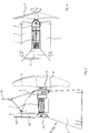
Das in
In den
Die erste Umlenkrolle
Die Funktion des Horizontalrührwerks ist Folgende:
Zum Absenken einer oberhalb des Nenn-Abwasserniveaus N befindlichen Montageeinheit M wird das umlaufende Seil S im Uhrzeigersinn um die erste Umlenkrolle
To lower a mounting unit M located above the nominal sewage level N, the circulating cable S is rotated clockwise about the
Ein oberer Befestigungspunkt B1 an der Montageeinheit M ist so gewählt, dass die Montageeinheit M beim Absenken eine Schräglage einnimmt. Wie insbesondere aus
Bei dem in
An der Montageeinheit M sind zwei fünfte Kuppelelemente
Mit dem Bezugszeichen
Beim Absenken wird das Montageelement M entlang des ersten Trums
Das vorgeschlagene Horizontalrührwerk lässt sich mit geringem Aufwand herstellen. Es kann insbesondere auf das Vorsehen einer vertikalen Säule oder eines vertikalen Pfeilers zum Führen der Montageeinheit M verzichtet werden. Mit dem vorgeschlagenen Horizontalrührwerk kann in besonders effizienter Weise eine Horizontalströmung in einem Klärbecken erzeugt werden. The proposed horizontal agitator can be produced with little effort. In particular, it can be dispensed with the provision of a vertical column or a vertical pillar for guiding the mounting unit M. With the proposed horizontal agitator, a horizontal flow can be generated in a clarifier in a particularly efficient manner.
BezugszeichenlisteLIST OF REFERENCE NUMBERS
- 11
- Tauchmotor submersible
- 22
- Getriebe transmission
- 33
- Propeller propeller
- 44
- erstes Strömungsleitelement first flow guide
- 55
- erstes Kuppelelement first coupling element
- 6 6
- drittes Kuppelelement third coupling element
- 77
- zweites Strömungsleitelement second flow guide
- 88th
- erste Trägerplatte first carrier plate
- 99
- zweite Trägerplatte second carrier plate
- 1010
- erstes Verbindungselement first connecting element
- 1111
- zweites Verbindungselement second connecting element
- 1212
- zweites Kuppelelement second coupling element
- 1313
- viertes Kuppelelement fourth coupling element
- 1414
- erstes Trum first run
- 1515
- erste Umlenkrolle first pulley
- 1616
- zweites Trum second run
- 1717
- erste Führung first guide
- 1818
- zweite Führung second leadership
- 1919
- drittes Verbindungselement third connecting element
- 2020
- Profilschiene rail
- 2121
- fünftes Kuppelelement fifth coupling element
- 2222
- sechstes Kuppelelement sixth coupling element
- AA
- Aufnahme admission
- B1B1
- oberer Befestigungspunkt upper attachment point
- B2B2
- unterer Befestigungspunkt lower attachment point
- BoBo
- Boden ground
- MM
- Montageeinheit assembly unit
- NN
- Nenn-Abwasserniveau Nominal wastewater level
- SS
- Seil rope
ZITATE ENTHALTEN IN DER BESCHREIBUNG QUOTES INCLUDE IN THE DESCRIPTION
Diese Liste der vom Anmelder aufgeführten Dokumente wurde automatisiert erzeugt und ist ausschließlich zur besseren Information des Lesers aufgenommen. Die Liste ist nicht Bestandteil der deutschen Patent- bzw. Gebrauchsmusteranmeldung. Das DPMA übernimmt keinerlei Haftung für etwaige Fehler oder Auslassungen.This list of the documents listed by the applicant has been generated automatically and is included solely for the better information of the reader. The list is not part of the German patent or utility model application. The DPMA assumes no liability for any errors or omissions.
Zitierte PatentliteraturCited patent literature
- US 4671872 [0002] US 4671872 [0002]
- WO 2008/101632 A1 [0003] WO 2008/101632 A1 [0003]
Claims (12)
Priority Applications (17)
| Application Number | Priority Date | Filing Date | Title |
|---|---|---|---|
| DE102012205579A DE102012205579A1 (en) | 2012-04-04 | 2012-04-04 | horizontal agitator |
| DE202012013493.0U DE202012013493U1 (en) | 2012-04-04 | 2012-04-04 | horizontal agitator |
| TW102106183A TWI587918B (en) | 2012-04-04 | 2013-02-22 | Horizontal blender |
| BR112014024944-0A BR112014024944B1 (en) | 2012-04-04 | 2013-03-20 | HORIZONTAL SHAKER |
| US14/389,788 US9957800B2 (en) | 2012-04-04 | 2013-03-20 | Horizontal agitator |
| EP13711875.8A EP2833992B1 (en) | 2012-04-04 | 2013-03-20 | Horizontal agitator |
| CA2867513A CA2867513C (en) | 2012-04-04 | 2013-03-20 | Horizontal agitator |
| JP2015503811A JP6328608B2 (en) | 2012-04-04 | 2013-03-20 | Horizontal stirring device |
| PL13711875T PL2833992T3 (en) | 2012-04-04 | 2013-03-20 | Horizontal agitator |
| CN201380016422.1A CN104245106B (en) | 2012-04-04 | 2013-03-20 | Horizontal agitator |
| DK13711875.8T DK2833992T3 (en) | 2012-04-04 | 2013-03-20 | Horizontal Agitator |
| HUE13711875A HUE027258T2 (en) | 2012-04-04 | 2013-03-20 | Horizontal agitator |
| PCT/EP2013/055838 WO2013149834A1 (en) | 2012-04-04 | 2013-03-20 | Horizontal agitator |
| ES13711875.8T ES2563856T3 (en) | 2012-04-04 | 2013-03-20 | Horizontal stirrer |
| MX2014011632A MX344231B (en) | 2012-04-04 | 2013-03-20 | Horizontal agitator. |
| KR1020147026814A KR101920895B1 (en) | 2012-04-04 | 2013-03-20 | Horizontal agitator |
| IL234745A IL234745A (en) | 2012-04-04 | 2014-09-18 | Horizontal agitator |
Applications Claiming Priority (1)
| Application Number | Priority Date | Filing Date | Title |
|---|---|---|---|
| DE102012205579A DE102012205579A1 (en) | 2012-04-04 | 2012-04-04 | horizontal agitator |
Publications (1)
| Publication Number | Publication Date |
|---|---|
| DE102012205579A1 true DE102012205579A1 (en) | 2013-10-10 |
Family
ID=47997424
Family Applications (2)
| Application Number | Title | Priority Date | Filing Date |
|---|---|---|---|
| DE202012013493.0U Expired - Lifetime DE202012013493U1 (en) | 2012-04-04 | 2012-04-04 | horizontal agitator |
| DE102012205579A Ceased DE102012205579A1 (en) | 2012-04-04 | 2012-04-04 | horizontal agitator |
Family Applications Before (1)
| Application Number | Title | Priority Date | Filing Date |
|---|---|---|---|
| DE202012013493.0U Expired - Lifetime DE202012013493U1 (en) | 2012-04-04 | 2012-04-04 | horizontal agitator |
Country Status (16)
| Country | Link |
|---|---|
| US (1) | US9957800B2 (en) |
| EP (1) | EP2833992B1 (en) |
| JP (1) | JP6328608B2 (en) |
| KR (1) | KR101920895B1 (en) |
| CN (1) | CN104245106B (en) |
| BR (1) | BR112014024944B1 (en) |
| CA (1) | CA2867513C (en) |
| DE (2) | DE202012013493U1 (en) |
| DK (1) | DK2833992T3 (en) |
| ES (1) | ES2563856T3 (en) |
| HU (1) | HUE027258T2 (en) |
| IL (1) | IL234745A (en) |
| MX (1) | MX344231B (en) |
| PL (1) | PL2833992T3 (en) |
| TW (1) | TWI587918B (en) |
| WO (1) | WO2013149834A1 (en) |
Families Citing this family (2)
| Publication number | Priority date | Publication date | Assignee | Title |
|---|---|---|---|---|
| CN105347526A (en) * | 2015-10-28 | 2016-02-24 | 桂林瑞丰环保微生物应用研究所 | Horizontal and vertical bidirectional vibration oil water deoiling method |
| CN112156685A (en) * | 2020-11-09 | 2021-01-01 | 中科广化(重庆)新材料研究院有限公司 | A agitating unit for sewage treatment |
Citations (3)
| Publication number | Priority date | Publication date | Assignee | Title |
|---|---|---|---|---|
| US4671872A (en) | 1986-03-18 | 1987-06-09 | Air-O-Lator Corporation | Aerator mast with azimuth lock and bottom stop |
| EP0531660A1 (en) * | 1991-07-17 | 1993-03-17 | E + M MASCHINENBAU GmbH | Guiding device for submersible stirring device |
| WO2008101632A1 (en) | 2007-02-19 | 2008-08-28 | Invent Umwelt- Und Verfahrenstechnik Ag | Horizontal agitator and method for producing a flow in a clearing basin using the horizontal agitator |
Family Cites Families (16)
| Publication number | Priority date | Publication date | Assignee | Title |
|---|---|---|---|---|
| JPS5589092A (en) * | 1978-12-19 | 1980-07-05 | Ebara Mfg | Mixer for reserve tank |
| US4464259A (en) * | 1982-09-30 | 1984-08-07 | Air-O-Lator Corporation | Hydraulic horizontal mixer |
| US4581182A (en) * | 1985-02-21 | 1986-04-08 | Air-O-Lator Corporation | Submersible mixer with air injection |
| JPH0420497Y2 (en) * | 1987-03-27 | 1992-05-11 | ||
| SE467292B (en) * | 1990-10-05 | 1992-06-29 | Flygt Ab | DEVICE FOR LETTING INSTALLABLE INSTALLATION OF A POLLUTABLE MOVER IN A WASHER CONTAINER |
| DE4120987C2 (en) * | 1991-06-25 | 1997-08-28 | Erwin Koeberle | From outside of a closed liquid container, e.g. a biogas plant, operable mechanical manipulator |
| DE19528701A1 (en) * | 1995-08-04 | 1997-02-06 | Wilo Gmbh | Rope guide for submersible pumps |
| DE19543525C1 (en) * | 1995-11-22 | 1997-02-06 | Itt Flygt Pumpen Gmbh | Device for handling submersible units |
| DE19620986C1 (en) * | 1996-05-24 | 1997-09-25 | Abs Pump Center Gmbh | Suspension device for travelling stirrer |
| DE19845545A1 (en) * | 1998-02-10 | 1999-08-12 | Fred Koch | Submerged mixer motor with reduction gear and vertical propeller |
| JP2002346359A (en) * | 2001-05-29 | 2002-12-03 | Shin Meiwa Ind Co Ltd | Propeller and underwater mixer |
| DE10150279A1 (en) * | 2001-10-05 | 2003-04-17 | Emu Unterwasserpumpen Gmbh | Immersed stirring device comprises stirring arrangement on guide tube and having immersed motor and propeller |
| DE10319760B4 (en) * | 2003-04-30 | 2015-05-13 | Abs Production Lohmar Gmbh | Suspension unit |
| JP2005199150A (en) * | 2004-01-14 | 2005-07-28 | Shin Meiwa Ind Co Ltd | Installation apparatus for submerged mixer |
| JP4990591B2 (en) * | 2006-09-29 | 2012-08-01 | 新明和工業株式会社 | Lifting device for underwater equipment |
| EP2689830B1 (en) * | 2012-07-26 | 2016-04-20 | Michael Niederbacher | Bio gas facility |
-
2012
- 2012-04-04 DE DE202012013493.0U patent/DE202012013493U1/en not_active Expired - Lifetime
- 2012-04-04 DE DE102012205579A patent/DE102012205579A1/en not_active Ceased
-
2013
- 2013-02-22 TW TW102106183A patent/TWI587918B/en active
- 2013-03-20 BR BR112014024944-0A patent/BR112014024944B1/en active IP Right Grant
- 2013-03-20 US US14/389,788 patent/US9957800B2/en active Active
- 2013-03-20 KR KR1020147026814A patent/KR101920895B1/en active IP Right Grant
- 2013-03-20 WO PCT/EP2013/055838 patent/WO2013149834A1/en active Application Filing
- 2013-03-20 CA CA2867513A patent/CA2867513C/en active Active
- 2013-03-20 HU HUE13711875A patent/HUE027258T2/en unknown
- 2013-03-20 MX MX2014011632A patent/MX344231B/en active IP Right Grant
- 2013-03-20 DK DK13711875.8T patent/DK2833992T3/en active
- 2013-03-20 ES ES13711875.8T patent/ES2563856T3/en active Active
- 2013-03-20 EP EP13711875.8A patent/EP2833992B1/en active Active
- 2013-03-20 JP JP2015503811A patent/JP6328608B2/en active Active
- 2013-03-20 PL PL13711875T patent/PL2833992T3/en unknown
- 2013-03-20 CN CN201380016422.1A patent/CN104245106B/en active Active
-
2014
- 2014-09-18 IL IL234745A patent/IL234745A/en active IP Right Grant
Patent Citations (3)
| Publication number | Priority date | Publication date | Assignee | Title |
|---|---|---|---|---|
| US4671872A (en) | 1986-03-18 | 1987-06-09 | Air-O-Lator Corporation | Aerator mast with azimuth lock and bottom stop |
| EP0531660A1 (en) * | 1991-07-17 | 1993-03-17 | E + M MASCHINENBAU GmbH | Guiding device for submersible stirring device |
| WO2008101632A1 (en) | 2007-02-19 | 2008-08-28 | Invent Umwelt- Und Verfahrenstechnik Ag | Horizontal agitator and method for producing a flow in a clearing basin using the horizontal agitator |
Also Published As
| Publication number | Publication date |
|---|---|
| US20150063998A1 (en) | 2015-03-05 |
| MX2014011632A (en) | 2014-10-17 |
| US9957800B2 (en) | 2018-05-01 |
| CA2867513C (en) | 2019-08-27 |
| CN104245106B (en) | 2016-10-12 |
| CA2867513A1 (en) | 2013-10-10 |
| KR101920895B1 (en) | 2019-02-13 |
| DK2833992T3 (en) | 2016-04-11 |
| MX344231B (en) | 2016-12-08 |
| JP2015514008A (en) | 2015-05-18 |
| WO2013149834A1 (en) | 2013-10-10 |
| BR112014024944A2 (en) | 2018-04-10 |
| TWI587918B (en) | 2017-06-21 |
| CN104245106A (en) | 2014-12-24 |
| PL2833992T3 (en) | 2016-07-29 |
| HUE027258T2 (en) | 2016-10-28 |
| KR20150002620A (en) | 2015-01-07 |
| BR112014024944B1 (en) | 2020-12-15 |
| ES2563856T3 (en) | 2016-03-16 |
| JP6328608B2 (en) | 2018-05-23 |
| TW201341047A (en) | 2013-10-16 |
| EP2833992B1 (en) | 2016-01-13 |
| IL234745A (en) | 2017-11-30 |
| EP2833992A1 (en) | 2015-02-11 |
| DE202012013493U1 (en) | 2017-03-03 |
Similar Documents
| Publication | Publication Date | Title |
|---|---|---|
| DE102008047341A1 (en) | Method for lifting components of wind turbines | |
| WO2015124135A1 (en) | Pump system for pumping viscous or partially viscous media out of a borehole | |
| EP2833992B1 (en) | Horizontal agitator | |
| DE102012111778A1 (en) | Rope clamp and lift system with rope clamp | |
| AT16486U1 (en) | conveyor system | |
| DE19501414A1 (en) | Arrangement for manipulating submersible operating equipment | |
| EP0144641B1 (en) | Service derrick for a well pump | |
| EP0122549A1 (en) | Lifting device for electrical submerged pump units | |
| DE102014101581A1 (en) | elevator system | |
| DE202012102170U1 (en) | Device for mounting / dismounting a component of a wind energy plant | |
| DE202010011174U1 (en) | Running track for a slope lift for people | |
| DE20109240U1 (en) | Roman blind with a single pull cord | |
| DE102012205577B3 (en) | horizontal agitator | |
| DE102014000285B4 (en) | Mobile load winch | |
| DE2133813A1 (en) | CAT VEHICLE | |
| EP4054967B1 (en) | Installation device for use in an elevator shaft | |
| DE102012210584A1 (en) | sliding door system | |
| DE19962298C2 (en) | Press-in device for pipes and drill rods | |
| DE102018129749B3 (en) | Ventilation system for aerating a liquid, in particular waste water, and liquid container | |
| AT10692U1 (en) | LIFTING AND SWIVELING DEVICE | |
| AT212227B (en) | Process for the creation of groundwater wells | |
| EP1045811B1 (en) | Cable elevator with a drive plate | |
| DE165200C (en) | ||
| DE2330696C3 (en) | Line piece for heating oil tank systems | |
| WO2003072480A1 (en) | Vertical lift system with an automatically travelling chain drive |
Legal Events
| Date | Code | Title | Description |
|---|---|---|---|
| R138 | Derivation of utility model |
Ref document number: 202012013493 Country of ref document: DE |
|
| R012 | Request for examination validly filed | ||
| R002 | Refusal decision in examination/registration proceedings | ||
| R003 | Refusal decision now final |