JP6328608B2 - Horizontal stirring device - Google Patents
Horizontal stirring device Download PDFInfo
- Publication number
- JP6328608B2 JP6328608B2 JP2015503811A JP2015503811A JP6328608B2 JP 6328608 B2 JP6328608 B2 JP 6328608B2 JP 2015503811 A JP2015503811 A JP 2015503811A JP 2015503811 A JP2015503811 A JP 2015503811A JP 6328608 B2 JP6328608 B2 JP 6328608B2
- Authority
- JP
- Japan
- Prior art keywords
- cable
- assembly unit
- horizontal
- mount
- coupling
- Prior art date
- Legal status (The legal status is an assumption and is not a legal conclusion. Google has not performed a legal analysis and makes no representation as to the accuracy of the status listed.)
- Active
Links
- 238000003756 stirring Methods 0.000 title claims description 42
- 230000008878 coupling Effects 0.000 claims description 80
- 238000010168 coupling process Methods 0.000 claims description 80
- 238000005859 coupling reaction Methods 0.000 claims description 80
- 238000013019 agitation Methods 0.000 claims description 12
- 238000007667 floating Methods 0.000 claims description 12
- 239000010865 sewage Substances 0.000 claims description 11
- 230000005484 gravity Effects 0.000 claims description 3
- XLYOFNOQVPJJNP-UHFFFAOYSA-N water Substances O XLYOFNOQVPJJNP-UHFFFAOYSA-N 0.000 description 10
- 238000000034 method Methods 0.000 description 5
- 230000005540 biological transmission Effects 0.000 description 3
- 238000005452 bending Methods 0.000 description 1
- 238000012423 maintenance Methods 0.000 description 1
Images


Classifications
-
- B—PERFORMING OPERATIONS; TRANSPORTING
- B01—PHYSICAL OR CHEMICAL PROCESSES OR APPARATUS IN GENERAL
- B01F—MIXING, e.g. DISSOLVING, EMULSIFYING OR DISPERSING
- B01F27/00—Mixers with rotary stirring devices in fixed receptacles; Kneaders
- B01F27/25—Mixers with both stirrer and drive unit submerged in the material being mixed
-
- B—PERFORMING OPERATIONS; TRANSPORTING
- B01—PHYSICAL OR CHEMICAL PROCESSES OR APPARATUS IN GENERAL
- B01F—MIXING, e.g. DISSOLVING, EMULSIFYING OR DISPERSING
- B01F27/00—Mixers with rotary stirring devices in fixed receptacles; Kneaders
- B01F27/60—Mixers with rotary stirring devices in fixed receptacles; Kneaders with stirrers rotating about a horizontal or inclined axis
- B01F27/71—Mixers with rotary stirring devices in fixed receptacles; Kneaders with stirrers rotating about a horizontal or inclined axis with propellers
-
- B—PERFORMING OPERATIONS; TRANSPORTING
- B01—PHYSICAL OR CHEMICAL PROCESSES OR APPARATUS IN GENERAL
- B01F—MIXING, e.g. DISSOLVING, EMULSIFYING OR DISPERSING
- B01F35/00—Accessories for mixers; Auxiliary operations or auxiliary devices; Parts or details of general application
- B01F35/40—Mounting or supporting mixing devices or receptacles; Clamping or holding arrangements therefor
-
- C—CHEMISTRY; METALLURGY
- C02—TREATMENT OF WATER, WASTE WATER, SEWAGE, OR SLUDGE
- C02F—TREATMENT OF WATER, WASTE WATER, SEWAGE, OR SLUDGE
- C02F1/00—Treatment of water, waste water, or sewage
-
- C—CHEMISTRY; METALLURGY
- C02—TREATMENT OF WATER, WASTE WATER, SEWAGE, OR SLUDGE
- C02F—TREATMENT OF WATER, WASTE WATER, SEWAGE, OR SLUDGE
- C02F3/00—Biological treatment of water, waste water, or sewage
- C02F3/02—Aerobic processes
- C02F3/12—Activated sludge processes
- C02F3/1278—Provisions for mixing or aeration of the mixed liquor
- C02F3/1284—Mixing devices
-
- F—MECHANICAL ENGINEERING; LIGHTING; HEATING; WEAPONS; BLASTING
- F01—MACHINES OR ENGINES IN GENERAL; ENGINE PLANTS IN GENERAL; STEAM ENGINES
- F01D—NON-POSITIVE DISPLACEMENT MACHINES OR ENGINES, e.g. STEAM TURBINES
- F01D5/00—Blades; Blade-carrying members; Heating, heat-insulating, cooling or antivibration means on the blades or the members
- F01D5/12—Blades
-
- B—PERFORMING OPERATIONS; TRANSPORTING
- B01—PHYSICAL OR CHEMICAL PROCESSES OR APPARATUS IN GENERAL
- B01F—MIXING, e.g. DISSOLVING, EMULSIFYING OR DISPERSING
- B01F35/00—Accessories for mixers; Auxiliary operations or auxiliary devices; Parts or details of general application
- B01F35/10—Maintenance of mixers
-
- C—CHEMISTRY; METALLURGY
- C02—TREATMENT OF WATER, WASTE WATER, SEWAGE, OR SLUDGE
- C02F—TREATMENT OF WATER, WASTE WATER, SEWAGE, OR SLUDGE
- C02F1/00—Treatment of water, waste water, or sewage
- C02F2001/007—Processes including a sedimentation step
-
- Y—GENERAL TAGGING OF NEW TECHNOLOGICAL DEVELOPMENTS; GENERAL TAGGING OF CROSS-SECTIONAL TECHNOLOGIES SPANNING OVER SEVERAL SECTIONS OF THE IPC; TECHNICAL SUBJECTS COVERED BY FORMER USPC CROSS-REFERENCE ART COLLECTIONS [XRACs] AND DIGESTS
- Y02—TECHNOLOGIES OR APPLICATIONS FOR MITIGATION OR ADAPTATION AGAINST CLIMATE CHANGE
- Y02W—CLIMATE CHANGE MITIGATION TECHNOLOGIES RELATED TO WASTEWATER TREATMENT OR WASTE MANAGEMENT
- Y02W10/00—Technologies for wastewater treatment
- Y02W10/10—Biological treatment of water, waste water, or sewage
Description
本発明は、請求項1の前提部に記載されているとおり水平型撹拌装置に関する。本発明は、さらに、水中モータと当該水中モータに駆動可能に接続されたプロペラとを含む組立ユニットを下降させる方法に関する。
The present invention relates to a horizontal stirrer as described in the premise of
一般的な水平型撹拌装置は、例えば特許文献1から知られている。水中モータが、プロペラと共に組立ユニットを形成する。この組立ユニットは、クラリファイヤーの壁に取り付けられて当該クラリファイヤーの底部で支持される支柱上で、鉛直方向に変位可能に案内される。この組立ユニットを昇降させるために、ケーブルウィンチが設けられる。この既知の水平型撹拌装置では、水中モータからプロペラの方向に向かって水の流れが生成される。このため、プロペラの水の吸引領域に位置する壁が、クラリファイヤー内に収容された水の効率的な水平方向の循環に対する抵抗となるので、この場合の水平方向の流れの生成効率はあまり良くない。
A general horizontal stirring device is known from
上記の構成と同じく支柱に取り付けられた水平型撹拌装置でありながら、上記の構成の短所を改善した水平型撹拌装置が、特許文献2から知られている。この水平型撹拌装置は、プロペラから水中モータに向かって水の流れを生成する。これにより、クラリファイヤーの壁および支柱のいずれも、プロペラによる汚水の吸引の阻害にならない。このような既知の水平型撹拌装置により、クラリファイヤーにおける汚水の水平方向の循環を優れた効率で行うことができる。
A horizontal agitation device which is a horizontal agitation device attached to a support column as in the above-mentioned configuration but which has improved the disadvantages of the above configuration is known from
本発明の目的は、さらに優れた効率を有する水平型撹拌装置を提供することである。本発明のさらなる目的は、そのような水平型撹拌装置を出来る限り簡単に且つ経済的に製造できるようにすることである。本発明のさらなる目的は、水中モータと当該水中モータに取り付けられたプロペラとで構成される組立ユニットを、修理および/または保守のためにクラリファイヤーの中から持ち上げられるようにすることである。 An object of the present invention is to provide a horizontal stirring apparatus having further excellent efficiency. A further object of the present invention is to make it possible to produce such a horizontal stirring device as simply and economically as possible. A further object of the present invention is to allow an assembly unit comprised of a submersible motor and a propeller attached to the submersible motor to be lifted out of the clarifier for repair and / or maintenance.
上記の目的は、請求項1の構成によって達成される。本発明の好適な実施形態は、請求項2〜12の構成から明らかである。
The above object is achieved by the structure of
本発明では、ガイド手段を、浮上位置とマウントとの間に延びる少なくとも1つの第1のケーブルを通過させるように形成する。この構成によれば、組立ユニットを案内するために従来設けられてきた支柱を省くことができる。これにより、その支柱による流動抵抗がなくなる。したがって、本発明の水平型撹拌装置により、クラリファイヤーにおける汚水の水平方向の循環を、極めて効率良く行うことができる。 In the present invention, the guide means is formed to pass at least one first cable extending between the floating position and the mount. According to this structure, the support | pillar conventionally provided in order to guide an assembly unit can be omitted. Thereby, the flow resistance by the support | pillar is lose | eliminated. Therefore, the horizontal stirring apparatus of the present invention can very efficiently circulate the sewage in the clarifier in the horizontal direction.
第1の実施形態において、前記第1のケーブルは、前記マウントに設けられた第1の進行方向反転装置によって案内され、当該第1のケーブルの第1の端部が、前記組立ユニットに取り付けられている。好ましくは、前記組立ユニットに設けられたガイドが、前記第1のケーブルを取り囲む。このようにして、前記組立ユニットを、前記第1のケーブルに沿って前記マウント上の組付位置へと案内することができる。 In the first embodiment, the first cable is guided by a first traveling direction reversing device provided on the mount, and a first end of the first cable is attached to the assembly unit. ing. Preferably, a guide provided in the assembly unit surrounds the first cable. In this way, the assembly unit can be guided along the first cable to an assembly position on the mount.
好ましくは、第2のケーブルであって、その第2の端部が前記組立ユニットに取り付けられた第2のケーブルが、前記組立ユニットを前記第1のケーブルに沿って動かすために設けられている。このような第2のケーブルは、前記組立ユニットを、上昇および/または下降させることができる。好ましくは、前記組立ユニットは当該組立ユニットに設けられた前記ガイドにより前記第1のケーブルに沿って案内される。 Preferably, a second cable, a second cable having a second end attached to the assembly unit, is provided for moving the assembly unit along the first cable. . Such a second cable can raise and / or lower the assembly unit. Preferably, the assembly unit is guided along the first cable by the guide provided in the assembly unit.
他の実施形態において、前記第1のケーブルの前記第1の端部は、前記組立ユニットにおける下方の取付ポイントで取り付けられており、前記第2のケーブルの前記第2の端部が、前記組立ユニットにおける少なくとも1つの上方の取付ポイントで取り付けられている。好ましくは、前記組立ユニットが少なくとも1つの上方の取付ポイントで懸架された際に、前記プロペラの軸心が前記クラリファイヤーの前記底部に対して傾く傾斜姿勢をその組立ユニットが取るように、前記上方の取付ポイントが前記組立ユニットの重心から少しずれている。このように前記組立ユニットが懸架状態で傾斜姿勢となることにより、当該組立ユニットを前記マウントに接続するのが極めて簡単になる。 In another embodiment, the first end of the first cable is attached at a lower attachment point in the assembly unit, and the second end of the second cable is attached to the assembly. It is attached at at least one upper attachment point in the unit. Preferably, when the assembly unit is suspended at at least one upper attachment point, the assembly unit takes an inclined posture in which the axis of the propeller is inclined with respect to the bottom of the clarifier. Are slightly deviated from the center of gravity of the assembly unit. Thus, since the assembly unit is in a tilted posture in a suspended state, it is extremely easy to connect the assembly unit to the mount.
好ましくは、前記第2のケーブルの前記第2の端部は、前記組立ユニットにおける前記上方の取付ポイントで着脱可能に取り付けられている。この目的のために、前記第2のケーブルの前記第2の端部にフックなどを取り付けて、前記組立ユニットの前記上方の取付ポイントに当該フックと対応するアイレット(小孔)、ブラケットなどを取り付けるようにしてもよい。この構成によれば、前記組立ユニットを前記マウント上に下降させた後、当該組立ユニットから前記第2のケーブルを外して、このケーブルを前記クラリファイヤーから取り出すことが可能になる。これにより、前記第2のケーブルによる流動抵抗をなくすことができ、さらに、前記水平型撹拌装置による前記クラリファイヤー内に入った汚水の循環効率を向上させることができる。 Preferably, the second end portion of the second cable is detachably attached at the upper attachment point in the assembly unit. For this purpose, a hook or the like is attached to the second end of the second cable, and an eyelet (small hole), a bracket or the like corresponding to the hook is attached to the upper attachment point of the assembly unit. You may do it. According to this configuration, after the assembly unit is lowered onto the mount, it is possible to remove the second cable from the assembly unit and take out the cable from the clarifier. Thereby, the flow resistance by the said 2nd cable can be eliminated, and also the circulation efficiency of the sewage which entered the said clarifier by the said horizontal stirring apparatus can be improved.
前記第2のケーブルの前記第2の端部に取り付けられたフックなどを引っ掛けるために、当該フックを(例えば、着脱可能に)取り付けた棒状体などを設けて、この棒状体などにより、前記フックなどを前記組立ユニットに設けられたアイレット、ブラケットなどに引っ掛けるようにしてもよい。 In order to hook a hook or the like attached to the second end of the second cable, a rod-like body to which the hook is attached (for example, detachable) is provided, and the hook is used by the rod-like body. Or the like may be hooked on an eyelet or a bracket provided in the assembly unit.
他の実施形態において、前記第1のケーブルの第3の端部が、前記基準の最高汚水面よりも上方に設けられた第1のウィンチに収容されており、前記第2のケーブルの第4の端部が、前記基準の最高汚水面よりも上方に設けられた第2のウィンチに収容されている。これらのウィンチ(好ましくは、当該ウィンチ同士は逆転機構を介して互いに接続される)により、前記組立ユニットの昇降が可能になる。例えば、これらのウィンチは、電気モータによって駆動される。 In another embodiment, the third end portion of the first cable is accommodated in a first winch provided above the reference maximum sewage surface, and the fourth end of the second cable is provided. Is accommodated in a second winch provided above the reference maximum sewage surface. These winches (preferably, the winches are connected to each other via a reverse rotation mechanism) allow the assembly unit to be raised and lowered. For example, these winches are driven by an electric motor.
特に好ましい一実施形態では、前記第1のケーブルと前記第2のケーブルとが、第2の進行方向反転装置によって前記浮上位置よりも上方で案内される循環するケーブルを形成するように組み合わされている。好ましくは、前記第2の進行方向反転装置は第3のウィンチである。例えば、前記第3のウィンチは、電気モータによって駆動される。 In a particularly preferred embodiment, the first cable and the second cable are combined so as to form a circulating cable guided above the flying position by a second traveling direction reversing device. Yes. Preferably, the second traveling direction reversing device is a third winch. For example, the third winch is driven by an electric motor.
好ましくは、前記第1のウィンチおよび前記第2のウィンチ、または、前記第2の進行方向反転装置が、前記浮上位置の領域に設けられたブリッジもしくはフレームに取り付けられている。この構成によれば、1つまたは複数の前記ケーブルの長さを短くすることができる。これにより、前記組立ユニットの運動経路が簡略化されるので、本発明の水平型撹拌装置の信頼度が極めて高くなる。 Preferably, the first winch and the second winch or the second traveling direction reversing device is attached to a bridge or a frame provided in the region of the floating position. According to this configuration, the length of one or a plurality of the cables can be shortened. As a result, the movement path of the assembly unit is simplified, so that the reliability of the horizontal stirring device of the present invention is extremely high.
他の実施形態では、前記組立ユニットが第1のカップリング装置を具備しており、前記マウントにその第1のカップリング装置と対応する第2のカップリング装置が設けられており、これら第1のカップリング装置と第2のカップリング装置との協働によって前記組立ユニットを前記マウントに着脱可能に接続することができる。好ましくは、前記第1のカップリング装置と前記第2のカップリング装置とが、前記第1のケーブルもしくは前記第2のケーブルを引っ張るか、または、循環するケーブルを用いる場合には当該循環するケーブルの第1の分岐ケーブルもしくは第2の分岐ケーブルを引っ張ることによって接続もしくは切離しが可能であるように形成されている。好ましくは、前記カップリング装置により、前記マウントと前記組立ユニットとの間で形状係合による接続部が形成される。この形状係合による接続部は、前記水平型撹拌装置が動作すると、互いに強制的に係止し合うので、補強されてより確実なものになる。 In another embodiment, the assembly unit includes a first coupling device, and the mount is provided with a second coupling device corresponding to the first coupling device. The assembly unit can be detachably connected to the mount by the cooperation of the coupling device and the second coupling device. Preferably, when the first coupling device and the second coupling device pull the first cable or the second cable or use a circulating cable, the circulating cable is used. The first branch cable or the second branch cable is pulled to be connected or disconnected. Preferably, the coupling device forms a connection portion by shape engagement between the mount and the assembly unit. Since the connecting portion by this shape engagement is forcibly locked with each other when the horizontal stirring device is operated, it is reinforced and more reliable.
前記第1のカップリング装置が第1のカップリング要素を有し、この第1のカップリング要素が、接続時に、前記第2のカップリング装置のうちの前記マウントに設けられた第2のカップリング要素と係合する。具体的には、前記第1のカップリング要素と前記第2のカップリング要素とが、前記組立ユニットが前記マウントに対して下降された際に傾いた状態でそのマウントと係合するように構成されている。 The first coupling device has a first coupling element, and the first coupling element is a second cup provided on the mount of the second coupling device when connected. Engage with the ring element. Specifically, the first coupling element and the second coupling element are configured to engage with the mount in an inclined state when the assembly unit is lowered with respect to the mount. Has been.
他の実施形態では、前記第1のカップリング装置が第3のカップリング要素を有しており、この第3のカップリング要素が、接続時に、前記第2のカップリング装置のうちの前記マウントに設けられた第4のカップリング要素と係合して挟持接続部または掛止め接続部を形成する。 In another embodiment, the first coupling device has a third coupling element that, when connected, the mount of the second coupling device. Engaging with a fourth coupling element provided on the to form a pinching connection or latching connection.
以下では、本発明の例示的な実施形態を、図面に基づいて詳細に説明する。 Hereinafter, exemplary embodiments of the present invention will be described in detail with reference to the drawings.
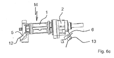
図1〜図5に示す水平型撹拌装置は、組立ユニット(その全体を符号Mで指す)を備える。組立ユニットMは、水中モータ1を含む。水中モータ1は、伝動機構2を介してプロペラ3を駆動することにより、プロペラ3からその水中モータ1の方向に向かう水平方向の水の流れを生成する。水中モータ1には、第1の流れ案内要素4が鉛直方向に延設されている。特に図6aから分かるように、組立ユニットMは、第1のカップリング装置を具備している。この第1のカップリング装置は、水中モータ1に延設された第1のカップリング要素5と、伝動機構2に延設された第3のカップリング要素6とを有する。
1 to 5 includes an assembly unit (the whole is indicated by a symbol M). The assembly unit M includes the
図1〜図5において、マウントには符号Aが付されている。このマウントAでは、2つのプレート状の第2の流れ案内要素7が、第1のキャリアプレート8および第2のキャリアプレート9を介して相互連結している。これらの第2の流れ案内要素7は、さらに、底部の側で、第1の連結要素10および第2の連結要素11を介して相互連結している。第1のキャリアプレート8および第2のキャリアプレート9は、第2のカップリング装置を保持している。この第2のカップリング装置は、第1のキャリアプレート8に延設された第2のカップリング要素12と、第2のキャリアプレート9に延設された第4のカップリング要素13とを有する。
In FIG. 1 to FIG. 5, a symbol A is attached to the mount. In this mount A, two plate-like second
図5に示すように、符号14は、循環するケーブルSのうち、第1のアイドラプーリ(遊び車)15とマウントAとの間に延びる第1の分岐ケーブルを指す。第2の分岐ケーブル16は、第1のアイドラプーリ15から、組立ユニットMにおける上方の取付ポイントB1へと延びる。好ましくは、上方の取付ポイントB1は、第1の流れ案内要素4に位置する。循環するケーブルSのうちの第1の分岐ケーブル14は、マウントAに設けられた第1のガイド17によって案内され、第1の分岐ケーブル14は、第1のキャリアプレート8内および第2のキャリアプレート9内を通過する。第1のガイド17はガイド手段の1つのガイド要素である。ケーブルSのうちの他方の端部は、組立ユニットMのうち、第3のカップリング要素6(図3)の領域に存在する下方の取付ポイントB2で取り付けられている。
As shown in FIG. 5,
図1に示すように、組立ユニットMは、第1の流れ案内要素4に取り付けられた第2のガイド18により、第1の分岐ケーブル14に沿って案内される。第2のガイド18は、ガイド手段の1つのガイド要素であり、第1の分岐ケーブル14を取り囲むスロットガイドであってもよいし、アイボルト(輪つきボルト)などであってもよい。図示のようにスロットガイドを利用することにより、組立ユニットMを、水平姿勢(図6dを参照)から傾斜姿勢(図6aを参照)へ回動させることができる。好ましくは、第1のガイド17(図2)は、第1のキャリアプレート8内および第2のキャリアプレート9内を通過する曲げパイプ(図示せず)である。その代わりに、第2のアイドラプーリ(図示せず)が設けられてもよい。
As shown in FIG. 1, the assembly unit M is guided along the
第1のアイドラプーリ15は、基準の汚水面Nよりも上方で、ブリッジ(図示せず)またはフレーム(図示せず)に取り付けられている。例えば、第1のアイドラプーリ15は、電気モータによって駆動される。図5では、クラリファイヤーの底部に符号Boが付されている。
The first
以下では、水平型撹拌装置の特徴について説明する。 Below, the characteristic of a horizontal type | mold stirring apparatus is demonstrated.
組立ユニットMを基準の汚水面Nよりも上方の位置から下降させるには、循環するケーブルSを、第1のアイドラプーリ15によって時計回りに動かす。これにより、組立ユニットMが、第2のガイド18により第1の分岐ケーブル14に沿って案内されながら、マウントAの方向に下降する。さらなる案内が、第2の分岐ケーブル16によって行われる。
In order to lower the assembly unit M from a position above the reference dirty water surface N, the circulating cable S is moved clockwise by the first
上方の取付ポイントB1は、組立ユニットMが下降する際に傾斜姿勢を取るように、組立ユニットMにおいて選択される。特に図6aから分かるように、その傾斜姿勢は、下降時にまず第1のカップリング要素5がマウントAに設けられた第2のカップリング要素12と係合するように選択される。ケーブルSを介して下方の取付ポイントB2に引張力を加えることにより、第3のカップリング要素6が、マウントAに取り付けられた第4のカップリング要素13と係合する。図6dに示す接続後の状態では、組立ユニットMが略水平姿勢を取る。この状態では、第3のカップリング要素6が第4のカップリング要素13に掛け止めされている。循環するケーブルSを第1のアイドラプーリ15によって反時計方向に動かすことにより、組立ユニットMを、上記とは逆の順番でマウントAから切り離すことができる。
The upper attachment point B1 is selected in the assembly unit M so as to take an inclined posture when the assembly unit M descends. As can be seen in particular in FIG. 6 a, the tilting position is selected such that the
図7に示す他の実施形態の水平型撹拌装置の場合には、第2の流れ案内要素7が、単一の第3の連結要素19を介して相互連結している。この第3の連結要素19は、組立ユニットMに面する上側の表面において、台形状のまたはV字形状(図示せず)のプロファイルレール20を具備している。
In the case of the horizontal stirrer of another embodiment shown in FIG. 7, the second
組立ユニットMには、2つの第5のカップリング要素21が取り付けられている。これら第5のカップリング要素21の形状は、第5のカップリング要素21がプロファイルレール20に実質的な形状係合によって取り付けられるように、そのプロファイルレール20の形状と対応している。
Two
符号22は、プロファイルレール20に取り付けられた第6のカップリング要素を指す。プロファイルレール20を具備する第3の連結要素19は、プロペラ3の方向に向かって下方に傾くようにして第2の流れ案内要素7に取り付けられている。
組立ユニットMは、下降する際には第2のガイド18により第1の分岐ケーブル14に沿って案内されて、第5のカップリング要素21がプロファイルレール20に取り付けられる。プロファイルレール20の傾きおよび第1の分岐ケーブル14によって生じる引張力により、第5のカップリング要素21が第6のカップリング要素22と強制的に接触する。この実施形態の水平型撹拌装置が動作すると、常にプロペラ3によって組立ユニットMに対して力が加えられ、この力が第5のカップリング要素21と第6のカップリング要素22とを互いに押し付け合う。
When the assembly unit M is lowered, the assembly unit M is guided along the
本発明の水平型撹拌装置は、低コストで製造することができる。具体的に述べると、組立ユニットMを案内するための鉛直方向の柱体や支柱を省くことができる。本発明の水平型撹拌装置により、クラリファイヤーにおける水平方向の水の流れを極めて効率良く生成することができる。
なお、本発明は、実施の態様として以下の内容を含む。
[態様1]
クラリファイヤーにおいて流れを生成する水平型撹拌装置であって、
水中モータ(1)と当該水中モータ(1)に駆動可能に接続されたプロペラ(3)とが組立ユニット(M)を形成しており、
前記組立ユニット(M)を着脱可能に取り付けるマウント(A)であって、前記クラリファイヤーの底部(Bo)によって支持されるマウント(A)が設けられており、
前記クラリファイヤーについて定められた基準の最高汚水面(N)よりも上方となる浮上位置と前記マウント(A)との間の略垂直方向の運動経路に沿って前記組立ユニット(M)を案内するガイド手段が設けられた、水平型撹拌装置において、
前記ガイド手段が、前記浮上位置と前記マウント(A)との間に延びる少なくとも1つの第1のケーブル(S)を通過させるように形成されていることを特徴とする、水平型撹拌装置。
[態様2]
態様1に記載の水平型撹拌装置において、前記第1のケーブルが、前記マウントに設けられた第1の進行方向反転装置によって案内され、当該第1のケーブル(S)の第1の端部が、前記組立ユニット(M)に取り付けられている、水平型撹拌装置。
[態様3]
態様1または2に記載の水平型撹拌装置において、前記組立ユニット(M)に設けられたガイド(18)が、前記第1のケーブルを取り囲む、水平型撹拌装置。
[態様4]
態様1から3のいずれか一態様に記載の水平型撹拌装置において、第2のケーブルであって、その第2の端部が前記組立ユニットに取り付けられた第2のケーブルが、前記組立ユニット(M)を前記第1のケーブルに沿って動かすために設けられている、水平型撹拌装置。
[態様5]
態様1から4のいずれか一態様に記載の水平型撹拌装置において、前記第1のケーブル(S)の前記第1の端部が、前記組立ユニット(M)における下方の取付ポイント(B2)で取り付けられており、前記第2のケーブル(S)の前記第2の端部が、前記組立ユニット(M)における少なくとも1つの上方の取付ポイント(B1)で取り付けられている、水平型撹拌装置。
[態様6]
態様1から5のいずれか一態様に記載の水平型撹拌装置において、前記組立ユニット(M)が少なくとも1つの上方の取付ポイント(B1)で懸架された際に、前記プロペラ(3)の軸心が前記クラリファイヤーの前記底部(Bo)に対して傾く傾斜姿勢をその組立ユニット(M)が取るように、前記上方の取付ポイント(B1)が前記組立ユニット(M)の重心から少しずれている、水平型撹拌装置。
[態様7]
態様1から6のいずれか一態様に記載の水平型撹拌装置において、前記第1のケーブルの第3の端部が、前記基準の最高汚水面(N)よりも上方に設けられた第1のウィンチに収容されており、前記第2のケーブルの第4の端部が、前記基準の最高汚水面(N)よりも上方に設けられた第2のウィンチに収容されている、水平型撹拌装置。
[態様8]
態様1から7のいずれか一態様に記載の水平型撹拌装置において、前記第1のケーブルと前記第2のケーブルとが、第2の進行方向反転装置(15)によって前記浮上位置よりも上方で案内される循環するケーブルを形成するように組み合わされており、好ましくは、前記第2の進行方向反転装置(15)が第3のウィンチである、水平型撹拌装置。
[態様9]
態様7または8に記載の水平型撹拌装置において、前記第1のウィンチおよび前記第2のウィンチ、または、前記第2の進行方向反転装置が、前記浮上位置の領域に設けられたブリッジもしくは前記浮上位置の領域に設置されたフレームに取り付けられている、水平型撹拌装置。
[態様10]
態様1から9のいずれか一態様に記載の水平型撹拌装置において、前記組立ユニット(M)が第1のカップリング装置を具備しており、前記マウント(A)にその第1のカップリング装置と対応する第2のカップリング装置が設けられており、これら第1のカップリング装置と第2のカップリング装置との協働によって前記組立ユニット(M)を前記マウント(A)に着脱可能に接続する、水平型撹拌装置。
[態様11]
態様1から10のいずれか一態様に記載の水平型撹拌装置において、前記第1のカップリング装置が第1のカップリング要素(5,21)を有しており、この第1のカップリング要素(5,21)が、接続時に、前記第2のカップリング装置のうちの前記マウント(A)に設けられた第2のカップリング要素(12,22)と係合する、水平型撹拌装置。[態様12]
態様1から11のいずれか一態様に記載の水平型撹拌装置において、前記第1のカップリング装置が第3のカップリング要素(6,21)を有しており、この第3のカップリング要素(6,21)が、接続時に、前記第2のカップリング装置のうちの前記マウント(A)に設けられた第4のカップリング要素(12,22)と係合して挟持接続部または掛止め接続部を形成する、水平型撹拌装置。
The horizontal stirring device of the present invention can be manufactured at low cost. Specifically, it is possible to omit a vertical column or column for guiding the assembly unit M. With the horizontal stirring device of the present invention, the horizontal water flow in the clarifier can be generated very efficiently.
In addition, this invention contains the following content as an aspect.
[Aspect 1]
A horizontal stirrer for generating a flow in a clarifier,
The submersible motor (1) and the propeller (3) drivably connected to the submersible motor (1) form an assembly unit (M).
A mount (A) for detachably mounting the assembly unit (M), the mount (A) supported by the bottom (Bo) of the clarifier;
The assembly unit (M) is guided along a substantially vertical movement path between the mount (A) and a floating position that is above the reference maximum sewage surface (N) defined for the clarifier. In a horizontal stirring device provided with a guide means,
The horizontal stirring device, wherein the guide means is formed so as to pass at least one first cable (S) extending between the floating position and the mount (A).
[Aspect 2]
In the horizontal stirring device according to
[Aspect 3]
The horizontal stirring apparatus according to the
[Aspect 4]
The horizontal stirring apparatus according to any one of
[Aspect 5]
In the horizontal stirring device according to any one of
[Aspect 6]
In the horizontal agitator according to any one of
[Aspect 7]
The horizontal stirrer according to any one of the
[Aspect 8]
In the horizontal stirring apparatus according to any one of
[Aspect 9]
9. The horizontal agitation device according to
[Aspect 10]
The horizontal stirring apparatus according to any one of
[Aspect 11]
The horizontal stirring apparatus according to any one of
The horizontal stirring apparatus according to any one of
1 水中モータ
2 伝動機構
3 プロペラ
4 第1の流れ案内要素
5 第1のカップリング要素
6 第3のカップリング要素
7 第2の流れ案内要素
8 第1のキャリアプレート
9 第2のキャリアプレート
10 第1の連結要素
11 第2の連結要素
12 第2のカップリング要素
13 第4のカップリング要素
14 第1の分岐ケーブル
15 第1のアイドラプーリ
16 第2の分岐ケーブル
17 第1のガイド
18 第2のガイド
19 第3の連結要素
20 プロファイルレール
21 第5のカップリング要素
22 第6のカップリング要素
A マウント
B1 上方の取付ポイント
B2 下方の取付ポイント
Bo 底部
M 組立ユニット
N 基準の汚水面
S ケーブル
DESCRIPTION OF
Claims (12)
水中モータ(1)と当該水中モータ(1)に駆動可能に接続されたプロペラ(3)とが組立ユニット(M)を形成しており、
前記組立ユニット(M)を着脱可能に取り付けるマウント(A)であって、前記クラリファイヤーの底部(Bo)によって支持されるマウント(A)が設けられており、
前記クラリファイヤーについて定められた基準の最高汚水面(N)よりも上方となる浮上位置と前記マウント(A)との間の略垂直方向の運動経路に沿って前記組立ユニット(M)を案内するガイド手段が設けられた、水平型撹拌装置において、
前記ガイド手段が、前記浮上位置と前記マウント(A)との間に延びる少なくとも1つの第1のケーブル(S)を通過させるように形成されていることを特徴とする、水平型撹拌装置。 A horizontal stirrer for generating a flow in a clarifier,
The submersible motor (1) and the propeller (3) drivably connected to the submersible motor (1) form an assembly unit (M).
A mount (A) for detachably mounting the assembly unit (M), the mount (A) supported by the bottom (Bo) of the clarifier;
The assembly unit (M) is guided along a substantially vertical movement path between the mount (A) and a floating position that is above the reference maximum sewage surface (N) defined for the clarifier. In a horizontal stirring device provided with a guide means,
The horizontal stirring device, wherein the guide means is formed so as to pass at least one first cable (S) extending between the floating position and the mount (A).
Applications Claiming Priority (3)
| Application Number | Priority Date | Filing Date | Title |
|---|---|---|---|
| DE102012205579.7 | 2012-04-04 | ||
| DE102012205579A DE102012205579A1 (en) | 2012-04-04 | 2012-04-04 | horizontal agitator |
| PCT/EP2013/055838 WO2013149834A1 (en) | 2012-04-04 | 2013-03-20 | Horizontal agitator |
Publications (3)
| Publication Number | Publication Date |
|---|---|
| JP2015514008A JP2015514008A (en) | 2015-05-18 |
| JP2015514008A5 JP2015514008A5 (en) | 2015-11-19 |
| JP6328608B2 true JP6328608B2 (en) | 2018-05-23 |
Family
ID=47997424
Family Applications (1)
| Application Number | Title | Priority Date | Filing Date |
|---|---|---|---|
| JP2015503811A Active JP6328608B2 (en) | 2012-04-04 | 2013-03-20 | Horizontal stirring device |
Country Status (16)
| Country | Link |
|---|---|
| US (1) | US9957800B2 (en) |
| EP (1) | EP2833992B1 (en) |
| JP (1) | JP6328608B2 (en) |
| KR (1) | KR101920895B1 (en) |
| CN (1) | CN104245106B (en) |
| BR (1) | BR112014024944B1 (en) |
| CA (1) | CA2867513C (en) |
| DE (2) | DE202012013493U1 (en) |
| DK (1) | DK2833992T3 (en) |
| ES (1) | ES2563856T3 (en) |
| HU (1) | HUE027258T2 (en) |
| IL (1) | IL234745A (en) |
| MX (1) | MX344231B (en) |
| PL (1) | PL2833992T3 (en) |
| TW (1) | TWI587918B (en) |
| WO (1) | WO2013149834A1 (en) |
Families Citing this family (2)
| Publication number | Priority date | Publication date | Assignee | Title |
|---|---|---|---|---|
| CN105347526A (en) * | 2015-10-28 | 2016-02-24 | 桂林瑞丰环保微生物应用研究所 | Horizontal and vertical bidirectional vibration oil water deoiling method |
| CN112156685A (en) * | 2020-11-09 | 2021-01-01 | 中科广化(重庆)新材料研究院有限公司 | A agitating unit for sewage treatment |
Family Cites Families (19)
| Publication number | Priority date | Publication date | Assignee | Title |
|---|---|---|---|---|
| JPS5589092A (en) * | 1978-12-19 | 1980-07-05 | Ebara Mfg | Mixer for reserve tank |
| US4464259A (en) * | 1982-09-30 | 1984-08-07 | Air-O-Lator Corporation | Hydraulic horizontal mixer |
| US4581182A (en) * | 1985-02-21 | 1986-04-08 | Air-O-Lator Corporation | Submersible mixer with air injection |
| US4671872A (en) | 1986-03-18 | 1987-06-09 | Air-O-Lator Corporation | Aerator mast with azimuth lock and bottom stop |
| JPH0420497Y2 (en) * | 1987-03-27 | 1992-05-11 | ||
| SE467292B (en) * | 1990-10-05 | 1992-06-29 | Flygt Ab | DEVICE FOR LETTING INSTALLABLE INSTALLATION OF A POLLUTABLE MOVER IN A WASHER CONTAINER |
| DE4120987C2 (en) * | 1991-06-25 | 1997-08-28 | Erwin Koeberle | From outside of a closed liquid container, e.g. a biogas plant, operable mechanical manipulator |
| DE4123664A1 (en) * | 1991-07-17 | 1993-01-21 | E & M Maschbau Gmbh | GUIDE DEVICE FOR A SUBMERSIBLE AGENCY OR THE LIKE |
| DE19528701A1 (en) * | 1995-08-04 | 1997-02-06 | Wilo Gmbh | Rope guide for submersible pumps |
| DE19543525C1 (en) * | 1995-11-22 | 1997-02-06 | Itt Flygt Pumpen Gmbh | Device for handling submersible units |
| DE19620986C1 (en) * | 1996-05-24 | 1997-09-25 | Abs Pump Center Gmbh | Suspension device for travelling stirrer |
| DE19845545A1 (en) * | 1998-02-10 | 1999-08-12 | Fred Koch | Submerged mixer motor with reduction gear and vertical propeller |
| JP2002346359A (en) * | 2001-05-29 | 2002-12-03 | Shin Meiwa Ind Co Ltd | Propeller and underwater mixer |
| DE10150279A1 (en) * | 2001-10-05 | 2003-04-17 | Emu Unterwasserpumpen Gmbh | Immersed stirring device comprises stirring arrangement on guide tube and having immersed motor and propeller |
| DE10319760B4 (en) * | 2003-04-30 | 2015-05-13 | Abs Production Lohmar Gmbh | Suspension unit |
| JP2005199150A (en) * | 2004-01-14 | 2005-07-28 | Shin Meiwa Ind Co Ltd | Installation apparatus for submerged mixer |
| JP4990591B2 (en) * | 2006-09-29 | 2012-08-01 | 新明和工業株式会社 | Lifting device for underwater equipment |
| DE102007008134A1 (en) | 2007-02-19 | 2008-08-21 | Invent Umwelt- Und Verfahrenstechnik Ag | Horizontal agitator and method for generating a flow in a clarifier with the horizontal agitator |
| EP2689830B1 (en) * | 2012-07-26 | 2016-04-20 | Michael Niederbacher | Bio gas facility |
-
2012
- 2012-04-04 DE DE202012013493.0U patent/DE202012013493U1/en not_active Expired - Lifetime
- 2012-04-04 DE DE102012205579A patent/DE102012205579A1/en not_active Ceased
-
2013
- 2013-02-22 TW TW102106183A patent/TWI587918B/en active
- 2013-03-20 WO PCT/EP2013/055838 patent/WO2013149834A1/en active Application Filing
- 2013-03-20 BR BR112014024944-0A patent/BR112014024944B1/en active IP Right Grant
- 2013-03-20 HU HUE13711875A patent/HUE027258T2/en unknown
- 2013-03-20 ES ES13711875.8T patent/ES2563856T3/en active Active
- 2013-03-20 JP JP2015503811A patent/JP6328608B2/en active Active
- 2013-03-20 PL PL13711875T patent/PL2833992T3/en unknown
- 2013-03-20 KR KR1020147026814A patent/KR101920895B1/en active IP Right Grant
- 2013-03-20 US US14/389,788 patent/US9957800B2/en active Active
- 2013-03-20 MX MX2014011632A patent/MX344231B/en active IP Right Grant
- 2013-03-20 DK DK13711875.8T patent/DK2833992T3/en active
- 2013-03-20 EP EP13711875.8A patent/EP2833992B1/en active Active
- 2013-03-20 CN CN201380016422.1A patent/CN104245106B/en active Active
- 2013-03-20 CA CA2867513A patent/CA2867513C/en active Active
-
2014
- 2014-09-18 IL IL234745A patent/IL234745A/en active IP Right Grant
Also Published As
| Publication number | Publication date |
|---|---|
| EP2833992A1 (en) | 2015-02-11 |
| KR101920895B1 (en) | 2019-02-13 |
| KR20150002620A (en) | 2015-01-07 |
| EP2833992B1 (en) | 2016-01-13 |
| ES2563856T3 (en) | 2016-03-16 |
| DK2833992T3 (en) | 2016-04-11 |
| US20150063998A1 (en) | 2015-03-05 |
| JP2015514008A (en) | 2015-05-18 |
| HUE027258T2 (en) | 2016-10-28 |
| BR112014024944B1 (en) | 2020-12-15 |
| MX2014011632A (en) | 2014-10-17 |
| MX344231B (en) | 2016-12-08 |
| US9957800B2 (en) | 2018-05-01 |
| BR112014024944A2 (en) | 2018-04-10 |
| DE102012205579A1 (en) | 2013-10-10 |
| CA2867513C (en) | 2019-08-27 |
| CN104245106B (en) | 2016-10-12 |
| DE202012013493U1 (en) | 2017-03-03 |
| IL234745A (en) | 2017-11-30 |
| TW201341047A (en) | 2013-10-16 |
| CA2867513A1 (en) | 2013-10-10 |
| WO2013149834A1 (en) | 2013-10-10 |
| CN104245106A (en) | 2014-12-24 |
| PL2833992T3 (en) | 2016-07-29 |
| TWI587918B (en) | 2017-06-21 |
Similar Documents
| Publication | Publication Date | Title |
|---|---|---|
| KR101239987B1 (en) | Azimuth thruster lifting system for ship | |
| JP6328608B2 (en) | Horizontal stirring device | |
| KR100967816B1 (en) | Method for mounting thruster in semi-submergible rig | |
| JP4990591B2 (en) | Lifting device for underwater equipment | |
| JP2013107765A (en) | Elevator device | |
| JP2015514008A5 (en) | ||
| KR20200017795A (en) | Multi-type submersible mixer | |
| CN203061170U (en) | Upper cover lifting device of reaction tank | |
| JP2010188300A (en) | Air diffuser | |
| JP2005095768A (en) | Apparatus for mounting submerged agitator and submerged agitation apparatus provided with the same | |
| JP6180503B2 (en) | Horizontal stirring device | |
| CN105668772A (en) | Lifting device of aerating system | |
| KR200268096Y1 (en) | Lifting and Transporting Equipment for the Support Frame of Membrane Module | |
| CN217527108U (en) | Sewage plug flow device | |
| JP7223274B2 (en) | winch fixing device | |
| JP2001248600A (en) | Elevation guiding mechanism in removable submerged pump | |
| JP2003181269A (en) | Agitation apparatus of sewage treating tank | |
| JP2005081239A (en) | Device of installing underwater stirrer | |
| KR101724111B1 (en) | Elevator | |
| JP2019051058A (en) | Acoustic reflection board device | |
| KR101095625B1 (en) | Flagpole connecting rod | |
| JP2006239605A (en) | Underwater stirring unit | |
| JP2007285085A (en) | Pool floor lifting device | |
| KR20130029844A (en) | Strand jack foundation for installing thruster | |
| JP2001070977A (en) | Aeration apparatus |
Legal Events
| Date | Code | Title | Description |
|---|---|---|---|
| A521 | Request for written amendment filed |
Free format text: JAPANESE INTERMEDIATE CODE: A523 Effective date: 20150930 |
|
| A621 | Written request for application examination |
Free format text: JAPANESE INTERMEDIATE CODE: A621 Effective date: 20150930 |
|
| A977 | Report on retrieval |
Free format text: JAPANESE INTERMEDIATE CODE: A971007 Effective date: 20161125 |
|
| A131 | Notification of reasons for refusal |
Free format text: JAPANESE INTERMEDIATE CODE: A131 Effective date: 20161129 |
|
| A521 | Request for written amendment filed |
Free format text: JAPANESE INTERMEDIATE CODE: A523 Effective date: 20170210 |
|
| A131 | Notification of reasons for refusal |
Free format text: JAPANESE INTERMEDIATE CODE: A131 Effective date: 20170627 |
|
| A521 | Request for written amendment filed |
Free format text: JAPANESE INTERMEDIATE CODE: A523 Effective date: 20170824 |
|
| A131 | Notification of reasons for refusal |
Free format text: JAPANESE INTERMEDIATE CODE: A131 Effective date: 20180109 |
|
| A521 | Request for written amendment filed |
Free format text: JAPANESE INTERMEDIATE CODE: A523 Effective date: 20180118 |
|
| TRDD | Decision of grant or rejection written | ||
| A01 | Written decision to grant a patent or to grant a registration (utility model) |
Free format text: JAPANESE INTERMEDIATE CODE: A01 Effective date: 20180403 |
|
| A61 | First payment of annual fees (during grant procedure) |
Free format text: JAPANESE INTERMEDIATE CODE: A61 Effective date: 20180418 |
|
| R150 | Certificate of patent or registration of utility model |
Ref document number: 6328608 Country of ref document: JP Free format text: JAPANESE INTERMEDIATE CODE: R150 |
|
| R250 | Receipt of annual fees |
Free format text: JAPANESE INTERMEDIATE CODE: R250 |
|
| R250 | Receipt of annual fees |
Free format text: JAPANESE INTERMEDIATE CODE: R250 |
|
| R250 | Receipt of annual fees |
Free format text: JAPANESE INTERMEDIATE CODE: R250 |