DE102011111786A1 - Method and apparatus for joining transfer or laminating film webs - Google Patents
Method and apparatus for joining transfer or laminating film webs Download PDFInfo
- Publication number
- DE102011111786A1 DE102011111786A1 DE102011111786A DE102011111786A DE102011111786A1 DE 102011111786 A1 DE102011111786 A1 DE 102011111786A1 DE 102011111786 A DE102011111786 A DE 102011111786A DE 102011111786 A DE102011111786 A DE 102011111786A DE 102011111786 A1 DE102011111786 A1 DE 102011111786A1
- Authority
- DE
- Germany
- Prior art keywords
- film
- film web
- welding head
- layer
- weld
- Prior art date
- Legal status (The legal status is an assumption and is not a legal conclusion. Google has not performed a legal analysis and makes no representation as to the accuracy of the status listed.)
- Ceased
Links
Images


Classifications
-
- B—PERFORMING OPERATIONS; TRANSPORTING
- B29—WORKING OF PLASTICS; WORKING OF SUBSTANCES IN A PLASTIC STATE IN GENERAL
- B29C—SHAPING OR JOINING OF PLASTICS; SHAPING OF MATERIAL IN A PLASTIC STATE, NOT OTHERWISE PROVIDED FOR; AFTER-TREATMENT OF THE SHAPED PRODUCTS, e.g. REPAIRING
- B29C65/00—Joining or sealing of preformed parts, e.g. welding of plastics materials; Apparatus therefor
- B29C65/02—Joining or sealing of preformed parts, e.g. welding of plastics materials; Apparatus therefor by heating, with or without pressure
- B29C65/06—Joining or sealing of preformed parts, e.g. welding of plastics materials; Apparatus therefor by heating, with or without pressure using friction, e.g. spin welding
- B29C65/069—Joining or sealing of preformed parts, e.g. welding of plastics materials; Apparatus therefor by heating, with or without pressure using friction, e.g. spin welding the welding tool cooperating with specially formed features of at least one of the parts to be joined, e.g. cooperating with holes or ribs of at least one of the parts to be joined
-
- B—PERFORMING OPERATIONS; TRANSPORTING
- B29—WORKING OF PLASTICS; WORKING OF SUBSTANCES IN A PLASTIC STATE IN GENERAL
- B29C—SHAPING OR JOINING OF PLASTICS; SHAPING OF MATERIAL IN A PLASTIC STATE, NOT OTHERWISE PROVIDED FOR; AFTER-TREATMENT OF THE SHAPED PRODUCTS, e.g. REPAIRING
- B29C65/00—Joining or sealing of preformed parts, e.g. welding of plastics materials; Apparatus therefor
- B29C65/02—Joining or sealing of preformed parts, e.g. welding of plastics materials; Apparatus therefor by heating, with or without pressure
- B29C65/08—Joining or sealing of preformed parts, e.g. welding of plastics materials; Apparatus therefor by heating, with or without pressure using ultrasonic vibrations
- B29C65/083—Joining or sealing of preformed parts, e.g. welding of plastics materials; Apparatus therefor by heating, with or without pressure using ultrasonic vibrations using a rotary sonotrode or a rotary anvil
- B29C65/087—Joining or sealing of preformed parts, e.g. welding of plastics materials; Apparatus therefor by heating, with or without pressure using ultrasonic vibrations using a rotary sonotrode or a rotary anvil using both a rotary sonotrode and a rotary anvil
-
- B—PERFORMING OPERATIONS; TRANSPORTING
- B29—WORKING OF PLASTICS; WORKING OF SUBSTANCES IN A PLASTIC STATE IN GENERAL
- B29C—SHAPING OR JOINING OF PLASTICS; SHAPING OF MATERIAL IN A PLASTIC STATE, NOT OTHERWISE PROVIDED FOR; AFTER-TREATMENT OF THE SHAPED PRODUCTS, e.g. REPAIRING
- B29C65/00—Joining or sealing of preformed parts, e.g. welding of plastics materials; Apparatus therefor
- B29C65/02—Joining or sealing of preformed parts, e.g. welding of plastics materials; Apparatus therefor by heating, with or without pressure
- B29C65/14—Joining or sealing of preformed parts, e.g. welding of plastics materials; Apparatus therefor by heating, with or without pressure using wave energy, i.e. electromagnetic radiation, or particle radiation
- B29C65/16—Laser beams
- B29C65/1629—Laser beams characterised by the way of heating the interface
- B29C65/1635—Laser beams characterised by the way of heating the interface at least passing through one of the parts to be joined, i.e. laser transmission welding
-
- B—PERFORMING OPERATIONS; TRANSPORTING
- B29—WORKING OF PLASTICS; WORKING OF SUBSTANCES IN A PLASTIC STATE IN GENERAL
- B29C—SHAPING OR JOINING OF PLASTICS; SHAPING OF MATERIAL IN A PLASTIC STATE, NOT OTHERWISE PROVIDED FOR; AFTER-TREATMENT OF THE SHAPED PRODUCTS, e.g. REPAIRING
- B29C65/00—Joining or sealing of preformed parts, e.g. welding of plastics materials; Apparatus therefor
- B29C65/02—Joining or sealing of preformed parts, e.g. welding of plastics materials; Apparatus therefor by heating, with or without pressure
- B29C65/14—Joining or sealing of preformed parts, e.g. welding of plastics materials; Apparatus therefor by heating, with or without pressure using wave energy, i.e. electromagnetic radiation, or particle radiation
- B29C65/16—Laser beams
- B29C65/1629—Laser beams characterised by the way of heating the interface
- B29C65/1654—Laser beams characterised by the way of heating the interface scanning at least one of the parts to be joined
-
- B—PERFORMING OPERATIONS; TRANSPORTING
- B29—WORKING OF PLASTICS; WORKING OF SUBSTANCES IN A PLASTIC STATE IN GENERAL
- B29C—SHAPING OR JOINING OF PLASTICS; SHAPING OF MATERIAL IN A PLASTIC STATE, NOT OTHERWISE PROVIDED FOR; AFTER-TREATMENT OF THE SHAPED PRODUCTS, e.g. REPAIRING
- B29C65/00—Joining or sealing of preformed parts, e.g. welding of plastics materials; Apparatus therefor
- B29C65/02—Joining or sealing of preformed parts, e.g. welding of plastics materials; Apparatus therefor by heating, with or without pressure
- B29C65/14—Joining or sealing of preformed parts, e.g. welding of plastics materials; Apparatus therefor by heating, with or without pressure using wave energy, i.e. electromagnetic radiation, or particle radiation
- B29C65/16—Laser beams
- B29C65/1629—Laser beams characterised by the way of heating the interface
- B29C65/1664—Laser beams characterised by the way of heating the interface making use of several radiators
-
- B—PERFORMING OPERATIONS; TRANSPORTING
- B29—WORKING OF PLASTICS; WORKING OF SUBSTANCES IN A PLASTIC STATE IN GENERAL
- B29C—SHAPING OR JOINING OF PLASTICS; SHAPING OF MATERIAL IN A PLASTIC STATE, NOT OTHERWISE PROVIDED FOR; AFTER-TREATMENT OF THE SHAPED PRODUCTS, e.g. REPAIRING
- B29C65/00—Joining or sealing of preformed parts, e.g. welding of plastics materials; Apparatus therefor
- B29C65/02—Joining or sealing of preformed parts, e.g. welding of plastics materials; Apparatus therefor by heating, with or without pressure
- B29C65/18—Joining or sealing of preformed parts, e.g. welding of plastics materials; Apparatus therefor by heating, with or without pressure using heated tools
- B29C65/22—Heated wire resistive ribbon, resistive band or resistive strip
- B29C65/221—Heated wire resistive ribbon, resistive band or resistive strip characterised by the type of heated wire, resistive ribbon, band or strip
- B29C65/222—Heated wire resistive ribbon, resistive band or resistive strip characterised by the type of heated wire, resistive ribbon, band or strip comprising at least a single heated wire
- B29C65/223—Heated wire resistive ribbon, resistive band or resistive strip characterised by the type of heated wire, resistive ribbon, band or strip comprising at least a single heated wire comprising several heated wires
-
- B—PERFORMING OPERATIONS; TRANSPORTING
- B29—WORKING OF PLASTICS; WORKING OF SUBSTANCES IN A PLASTIC STATE IN GENERAL
- B29C—SHAPING OR JOINING OF PLASTICS; SHAPING OF MATERIAL IN A PLASTIC STATE, NOT OTHERWISE PROVIDED FOR; AFTER-TREATMENT OF THE SHAPED PRODUCTS, e.g. REPAIRING
- B29C65/00—Joining or sealing of preformed parts, e.g. welding of plastics materials; Apparatus therefor
- B29C65/48—Joining or sealing of preformed parts, e.g. welding of plastics materials; Apparatus therefor using adhesives, i.e. using supplementary joining material; solvent bonding
- B29C65/50—Joining or sealing of preformed parts, e.g. welding of plastics materials; Apparatus therefor using adhesives, i.e. using supplementary joining material; solvent bonding using adhesive tape, e.g. thermoplastic tape; using threads or the like
- B29C65/5042—Joining or sealing of preformed parts, e.g. welding of plastics materials; Apparatus therefor using adhesives, i.e. using supplementary joining material; solvent bonding using adhesive tape, e.g. thermoplastic tape; using threads or the like covering both elements to be joined
-
- B—PERFORMING OPERATIONS; TRANSPORTING
- B29—WORKING OF PLASTICS; WORKING OF SUBSTANCES IN A PLASTIC STATE IN GENERAL
- B29C—SHAPING OR JOINING OF PLASTICS; SHAPING OF MATERIAL IN A PLASTIC STATE, NOT OTHERWISE PROVIDED FOR; AFTER-TREATMENT OF THE SHAPED PRODUCTS, e.g. REPAIRING
- B29C65/00—Joining or sealing of preformed parts, e.g. welding of plastics materials; Apparatus therefor
- B29C65/78—Means for handling the parts to be joined, e.g. for making containers or hollow articles, e.g. means for handling sheets, plates, web-like materials, tubular articles, hollow articles or elements to be joined therewith; Means for discharging the joined articles from the joining apparatus
- B29C65/7802—Positioning the parts to be joined, e.g. aligning, indexing or centring
- B29C65/7805—Positioning the parts to be joined, e.g. aligning, indexing or centring the parts to be joined comprising positioning features
- B29C65/7817—Positioning the parts to be joined, e.g. aligning, indexing or centring the parts to be joined comprising positioning features in the form of positioning marks
-
- B—PERFORMING OPERATIONS; TRANSPORTING
- B29—WORKING OF PLASTICS; WORKING OF SUBSTANCES IN A PLASTIC STATE IN GENERAL
- B29C—SHAPING OR JOINING OF PLASTICS; SHAPING OF MATERIAL IN A PLASTIC STATE, NOT OTHERWISE PROVIDED FOR; AFTER-TREATMENT OF THE SHAPED PRODUCTS, e.g. REPAIRING
- B29C65/00—Joining or sealing of preformed parts, e.g. welding of plastics materials; Apparatus therefor
- B29C65/78—Means for handling the parts to be joined, e.g. for making containers or hollow articles, e.g. means for handling sheets, plates, web-like materials, tubular articles, hollow articles or elements to be joined therewith; Means for discharging the joined articles from the joining apparatus
- B29C65/7802—Positioning the parts to be joined, e.g. aligning, indexing or centring
- B29C65/7832—Positioning the parts to be joined, e.g. aligning, indexing or centring by setting the overlap between the parts to be joined, e.g. the overlap between sheets, plates or web-like materials
-
- B—PERFORMING OPERATIONS; TRANSPORTING
- B29—WORKING OF PLASTICS; WORKING OF SUBSTANCES IN A PLASTIC STATE IN GENERAL
- B29C—SHAPING OR JOINING OF PLASTICS; SHAPING OF MATERIAL IN A PLASTIC STATE, NOT OTHERWISE PROVIDED FOR; AFTER-TREATMENT OF THE SHAPED PRODUCTS, e.g. REPAIRING
- B29C65/00—Joining or sealing of preformed parts, e.g. welding of plastics materials; Apparatus therefor
- B29C65/78—Means for handling the parts to be joined, e.g. for making containers or hollow articles, e.g. means for handling sheets, plates, web-like materials, tubular articles, hollow articles or elements to be joined therewith; Means for discharging the joined articles from the joining apparatus
- B29C65/7858—Means for handling the parts to be joined, e.g. for making containers or hollow articles, e.g. means for handling sheets, plates, web-like materials, tubular articles, hollow articles or elements to be joined therewith; Means for discharging the joined articles from the joining apparatus characterised by the feeding movement of the parts to be joined
- B29C65/7888—Means for handling of moving sheets or webs
- B29C65/7891—Means for handling of moving sheets or webs of discontinuously moving sheets or webs
-
- B—PERFORMING OPERATIONS; TRANSPORTING
- B29—WORKING OF PLASTICS; WORKING OF SUBSTANCES IN A PLASTIC STATE IN GENERAL
- B29C—SHAPING OR JOINING OF PLASTICS; SHAPING OF MATERIAL IN A PLASTIC STATE, NOT OTHERWISE PROVIDED FOR; AFTER-TREATMENT OF THE SHAPED PRODUCTS, e.g. REPAIRING
- B29C66/00—General aspects of processes or apparatus for joining preformed parts
- B29C66/01—General aspects dealing with the joint area or with the area to be joined
- B29C66/05—Particular design of joint configurations
- B29C66/10—Particular design of joint configurations particular design of the joint cross-sections
- B29C66/11—Joint cross-sections comprising a single joint-segment, i.e. one of the parts to be joined comprising a single joint-segment in the joint cross-section
- B29C66/112—Single lapped joints
- B29C66/1122—Single lap to lap joints, i.e. overlap joints
-
- B—PERFORMING OPERATIONS; TRANSPORTING
- B29—WORKING OF PLASTICS; WORKING OF SUBSTANCES IN A PLASTIC STATE IN GENERAL
- B29C—SHAPING OR JOINING OF PLASTICS; SHAPING OF MATERIAL IN A PLASTIC STATE, NOT OTHERWISE PROVIDED FOR; AFTER-TREATMENT OF THE SHAPED PRODUCTS, e.g. REPAIRING
- B29C66/00—General aspects of processes or apparatus for joining preformed parts
- B29C66/01—General aspects dealing with the joint area or with the area to be joined
- B29C66/05—Particular design of joint configurations
- B29C66/10—Particular design of joint configurations particular design of the joint cross-sections
- B29C66/11—Joint cross-sections comprising a single joint-segment, i.e. one of the parts to be joined comprising a single joint-segment in the joint cross-section
- B29C66/114—Single butt joints
- B29C66/1142—Single butt to butt joints
-
- B—PERFORMING OPERATIONS; TRANSPORTING
- B29—WORKING OF PLASTICS; WORKING OF SUBSTANCES IN A PLASTIC STATE IN GENERAL
- B29C—SHAPING OR JOINING OF PLASTICS; SHAPING OF MATERIAL IN A PLASTIC STATE, NOT OTHERWISE PROVIDED FOR; AFTER-TREATMENT OF THE SHAPED PRODUCTS, e.g. REPAIRING
- B29C66/00—General aspects of processes or apparatus for joining preformed parts
- B29C66/01—General aspects dealing with the joint area or with the area to be joined
- B29C66/05—Particular design of joint configurations
- B29C66/10—Particular design of joint configurations particular design of the joint cross-sections
- B29C66/13—Single flanged joints; Fin-type joints; Single hem joints; Edge joints; Interpenetrating fingered joints; Other specific particular designs of joint cross-sections not provided for in groups B29C66/11 - B29C66/12
- B29C66/135—Single hemmed joints, i.e. one of the parts to be joined being hemmed in the joint area
- B29C66/1352—Single hem to hem joints
-
- B—PERFORMING OPERATIONS; TRANSPORTING
- B29—WORKING OF PLASTICS; WORKING OF SUBSTANCES IN A PLASTIC STATE IN GENERAL
- B29C—SHAPING OR JOINING OF PLASTICS; SHAPING OF MATERIAL IN A PLASTIC STATE, NOT OTHERWISE PROVIDED FOR; AFTER-TREATMENT OF THE SHAPED PRODUCTS, e.g. REPAIRING
- B29C66/00—General aspects of processes or apparatus for joining preformed parts
- B29C66/01—General aspects dealing with the joint area or with the area to be joined
- B29C66/05—Particular design of joint configurations
- B29C66/20—Particular design of joint configurations particular design of the joint lines, e.g. of the weld lines
- B29C66/23—Particular design of joint configurations particular design of the joint lines, e.g. of the weld lines said joint lines being multiple and parallel or being in the form of tessellations
- B29C66/232—Particular design of joint configurations particular design of the joint lines, e.g. of the weld lines said joint lines being multiple and parallel or being in the form of tessellations said joint lines being multiple and parallel, i.e. the joint being formed by several parallel joint lines
-
- B—PERFORMING OPERATIONS; TRANSPORTING
- B29—WORKING OF PLASTICS; WORKING OF SUBSTANCES IN A PLASTIC STATE IN GENERAL
- B29C—SHAPING OR JOINING OF PLASTICS; SHAPING OF MATERIAL IN A PLASTIC STATE, NOT OTHERWISE PROVIDED FOR; AFTER-TREATMENT OF THE SHAPED PRODUCTS, e.g. REPAIRING
- B29C66/00—General aspects of processes or apparatus for joining preformed parts
- B29C66/40—General aspects of joining substantially flat articles, e.g. plates, sheets or web-like materials; Making flat seams in tubular or hollow articles; Joining single elements to substantially flat surfaces
- B29C66/41—Joining substantially flat articles ; Making flat seams in tubular or hollow articles
- B29C66/43—Joining a relatively small portion of the surface of said articles
-
- B—PERFORMING OPERATIONS; TRANSPORTING
- B29—WORKING OF PLASTICS; WORKING OF SUBSTANCES IN A PLASTIC STATE IN GENERAL
- B29C—SHAPING OR JOINING OF PLASTICS; SHAPING OF MATERIAL IN A PLASTIC STATE, NOT OTHERWISE PROVIDED FOR; AFTER-TREATMENT OF THE SHAPED PRODUCTS, e.g. REPAIRING
- B29C66/00—General aspects of processes or apparatus for joining preformed parts
- B29C66/70—General aspects of processes or apparatus for joining preformed parts characterised by the composition, physical properties or the structure of the material of the parts to be joined; Joining with non-plastics material
- B29C66/72—General aspects of processes or apparatus for joining preformed parts characterised by the composition, physical properties or the structure of the material of the parts to be joined; Joining with non-plastics material characterised by the structure of the material of the parts to be joined
- B29C66/723—General aspects of processes or apparatus for joining preformed parts characterised by the composition, physical properties or the structure of the material of the parts to be joined; Joining with non-plastics material characterised by the structure of the material of the parts to be joined being multi-layered
-
- B—PERFORMING OPERATIONS; TRANSPORTING
- B29—WORKING OF PLASTICS; WORKING OF SUBSTANCES IN A PLASTIC STATE IN GENERAL
- B29C—SHAPING OR JOINING OF PLASTICS; SHAPING OF MATERIAL IN A PLASTIC STATE, NOT OTHERWISE PROVIDED FOR; AFTER-TREATMENT OF THE SHAPED PRODUCTS, e.g. REPAIRING
- B29C66/00—General aspects of processes or apparatus for joining preformed parts
- B29C66/80—General aspects of machine operations or constructions and parts thereof
- B29C66/81—General aspects of the pressing elements, i.e. the elements applying pressure on the parts to be joined in the area to be joined, e.g. the welding jaws or clamps
- B29C66/812—General aspects of the pressing elements, i.e. the elements applying pressure on the parts to be joined in the area to be joined, e.g. the welding jaws or clamps characterised by the composition, by the structure, by the intensive physical properties or by the optical properties of the material constituting the pressing elements, e.g. constituting the welding jaws or clamps
- B29C66/8126—General aspects of the pressing elements, i.e. the elements applying pressure on the parts to be joined in the area to be joined, e.g. the welding jaws or clamps characterised by the composition, by the structure, by the intensive physical properties or by the optical properties of the material constituting the pressing elements, e.g. constituting the welding jaws or clamps characterised by the intensive physical properties or by the optical properties of the material constituting the pressing elements, e.g. constituting the welding jaws or clamps
- B29C66/81266—Optical properties, e.g. transparency, reflectivity
- B29C66/81267—Transparent to electromagnetic radiation, e.g. to visible light
-
- B—PERFORMING OPERATIONS; TRANSPORTING
- B29—WORKING OF PLASTICS; WORKING OF SUBSTANCES IN A PLASTIC STATE IN GENERAL
- B29C—SHAPING OR JOINING OF PLASTICS; SHAPING OF MATERIAL IN A PLASTIC STATE, NOT OTHERWISE PROVIDED FOR; AFTER-TREATMENT OF THE SHAPED PRODUCTS, e.g. REPAIRING
- B29C66/00—General aspects of processes or apparatus for joining preformed parts
- B29C66/80—General aspects of machine operations or constructions and parts thereof
- B29C66/81—General aspects of the pressing elements, i.e. the elements applying pressure on the parts to be joined in the area to be joined, e.g. the welding jaws or clamps
- B29C66/814—General aspects of the pressing elements, i.e. the elements applying pressure on the parts to be joined in the area to be joined, e.g. the welding jaws or clamps characterised by the design of the pressing elements, e.g. of the welding jaws or clamps
- B29C66/8141—General aspects of the pressing elements, i.e. the elements applying pressure on the parts to be joined in the area to be joined, e.g. the welding jaws or clamps characterised by the design of the pressing elements, e.g. of the welding jaws or clamps characterised by the surface geometry of the part of the pressing elements, e.g. welding jaws or clamps, coming into contact with the parts to be joined
- B29C66/81427—General aspects of the pressing elements, i.e. the elements applying pressure on the parts to be joined in the area to be joined, e.g. the welding jaws or clamps characterised by the design of the pressing elements, e.g. of the welding jaws or clamps characterised by the surface geometry of the part of the pressing elements, e.g. welding jaws or clamps, coming into contact with the parts to be joined comprising a single ridge, e.g. for making a weakening line; comprising a single tooth
-
- B—PERFORMING OPERATIONS; TRANSPORTING
- B29—WORKING OF PLASTICS; WORKING OF SUBSTANCES IN A PLASTIC STATE IN GENERAL
- B29C—SHAPING OR JOINING OF PLASTICS; SHAPING OF MATERIAL IN A PLASTIC STATE, NOT OTHERWISE PROVIDED FOR; AFTER-TREATMENT OF THE SHAPED PRODUCTS, e.g. REPAIRING
- B29C66/00—General aspects of processes or apparatus for joining preformed parts
- B29C66/80—General aspects of machine operations or constructions and parts thereof
- B29C66/83—General aspects of machine operations or constructions and parts thereof characterised by the movement of the joining or pressing tools
- B29C66/832—Reciprocating joining or pressing tools
- B29C66/8322—Joining or pressing tools reciprocating along one axis
-
- B—PERFORMING OPERATIONS; TRANSPORTING
- B29—WORKING OF PLASTICS; WORKING OF SUBSTANCES IN A PLASTIC STATE IN GENERAL
- B29C—SHAPING OR JOINING OF PLASTICS; SHAPING OF MATERIAL IN A PLASTIC STATE, NOT OTHERWISE PROVIDED FOR; AFTER-TREATMENT OF THE SHAPED PRODUCTS, e.g. REPAIRING
- B29C66/00—General aspects of processes or apparatus for joining preformed parts
- B29C66/80—General aspects of machine operations or constructions and parts thereof
- B29C66/83—General aspects of machine operations or constructions and parts thereof characterised by the movement of the joining or pressing tools
- B29C66/836—Moving relative to and tangentially to the parts to be joined, e.g. transversely to the displacement of the parts to be joined, e.g. using a X-Y table
- B29C66/8362—Rollers, cylinders or drums moving relative to and tangentially to the parts to be joined
-
- B—PERFORMING OPERATIONS; TRANSPORTING
- B29—WORKING OF PLASTICS; WORKING OF SUBSTANCES IN A PLASTIC STATE IN GENERAL
- B29C—SHAPING OR JOINING OF PLASTICS; SHAPING OF MATERIAL IN A PLASTIC STATE, NOT OTHERWISE PROVIDED FOR; AFTER-TREATMENT OF THE SHAPED PRODUCTS, e.g. REPAIRING
- B29C66/00—General aspects of processes or apparatus for joining preformed parts
- B29C66/90—Measuring or controlling the joining process
- B29C66/98—Determining the joining area by using markings on at least one of the parts to be joined
-
- B—PERFORMING OPERATIONS; TRANSPORTING
- B65—CONVEYING; PACKING; STORING; HANDLING THIN OR FILAMENTARY MATERIAL
- B65H—HANDLING THIN OR FILAMENTARY MATERIAL, e.g. SHEETS, WEBS, CABLES
- B65H21/00—Apparatus for splicing webs
-
- B—PERFORMING OPERATIONS; TRANSPORTING
- B65—CONVEYING; PACKING; STORING; HANDLING THIN OR FILAMENTARY MATERIAL
- B65H—HANDLING THIN OR FILAMENTARY MATERIAL, e.g. SHEETS, WEBS, CABLES
- B65H21/00—Apparatus for splicing webs
- B65H21/02—Apparatus for splicing webs for premarked, e.g. preprinted, webs
-
- B—PERFORMING OPERATIONS; TRANSPORTING
- B29—WORKING OF PLASTICS; WORKING OF SUBSTANCES IN A PLASTIC STATE IN GENERAL
- B29C—SHAPING OR JOINING OF PLASTICS; SHAPING OF MATERIAL IN A PLASTIC STATE, NOT OTHERWISE PROVIDED FOR; AFTER-TREATMENT OF THE SHAPED PRODUCTS, e.g. REPAIRING
- B29C2795/00—Printing on articles made from plastics or substances in a plastic state
- B29C2795/002—Printing on articles made from plastics or substances in a plastic state before shaping
-
- B—PERFORMING OPERATIONS; TRANSPORTING
- B29—WORKING OF PLASTICS; WORKING OF SUBSTANCES IN A PLASTIC STATE IN GENERAL
- B29C—SHAPING OR JOINING OF PLASTICS; SHAPING OF MATERIAL IN A PLASTIC STATE, NOT OTHERWISE PROVIDED FOR; AFTER-TREATMENT OF THE SHAPED PRODUCTS, e.g. REPAIRING
- B29C65/00—Joining or sealing of preformed parts, e.g. welding of plastics materials; Apparatus therefor
- B29C65/02—Joining or sealing of preformed parts, e.g. welding of plastics materials; Apparatus therefor by heating, with or without pressure
- B29C65/14—Joining or sealing of preformed parts, e.g. welding of plastics materials; Apparatus therefor by heating, with or without pressure using wave energy, i.e. electromagnetic radiation, or particle radiation
- B29C65/16—Laser beams
- B29C65/1629—Laser beams characterised by the way of heating the interface
- B29C65/1635—Laser beams characterised by the way of heating the interface at least passing through one of the parts to be joined, i.e. laser transmission welding
- B29C65/1638—Laser beams characterised by the way of heating the interface at least passing through one of the parts to be joined, i.e. laser transmission welding focusing the laser beam on the interface
-
- B—PERFORMING OPERATIONS; TRANSPORTING
- B29—WORKING OF PLASTICS; WORKING OF SUBSTANCES IN A PLASTIC STATE IN GENERAL
- B29C—SHAPING OR JOINING OF PLASTICS; SHAPING OF MATERIAL IN A PLASTIC STATE, NOT OTHERWISE PROVIDED FOR; AFTER-TREATMENT OF THE SHAPED PRODUCTS, e.g. REPAIRING
- B29C65/00—Joining or sealing of preformed parts, e.g. welding of plastics materials; Apparatus therefor
- B29C65/02—Joining or sealing of preformed parts, e.g. welding of plastics materials; Apparatus therefor by heating, with or without pressure
- B29C65/14—Joining or sealing of preformed parts, e.g. welding of plastics materials; Apparatus therefor by heating, with or without pressure using wave energy, i.e. electromagnetic radiation, or particle radiation
- B29C65/16—Laser beams
- B29C65/1677—Laser beams making use of an absorber or impact modifier
- B29C65/168—Laser beams making use of an absorber or impact modifier placed at the interface
-
- B—PERFORMING OPERATIONS; TRANSPORTING
- B29—WORKING OF PLASTICS; WORKING OF SUBSTANCES IN A PLASTIC STATE IN GENERAL
- B29C—SHAPING OR JOINING OF PLASTICS; SHAPING OF MATERIAL IN A PLASTIC STATE, NOT OTHERWISE PROVIDED FOR; AFTER-TREATMENT OF THE SHAPED PRODUCTS, e.g. REPAIRING
- B29C65/00—Joining or sealing of preformed parts, e.g. welding of plastics materials; Apparatus therefor
- B29C65/02—Joining or sealing of preformed parts, e.g. welding of plastics materials; Apparatus therefor by heating, with or without pressure
- B29C65/14—Joining or sealing of preformed parts, e.g. welding of plastics materials; Apparatus therefor by heating, with or without pressure using wave energy, i.e. electromagnetic radiation, or particle radiation
- B29C65/16—Laser beams
- B29C65/1677—Laser beams making use of an absorber or impact modifier
- B29C65/1683—Laser beams making use of an absorber or impact modifier coated on the article
-
- B—PERFORMING OPERATIONS; TRANSPORTING
- B29—WORKING OF PLASTICS; WORKING OF SUBSTANCES IN A PLASTIC STATE IN GENERAL
- B29C—SHAPING OR JOINING OF PLASTICS; SHAPING OF MATERIAL IN A PLASTIC STATE, NOT OTHERWISE PROVIDED FOR; AFTER-TREATMENT OF THE SHAPED PRODUCTS, e.g. REPAIRING
- B29C65/00—Joining or sealing of preformed parts, e.g. welding of plastics materials; Apparatus therefor
- B29C65/02—Joining or sealing of preformed parts, e.g. welding of plastics materials; Apparatus therefor by heating, with or without pressure
- B29C65/18—Joining or sealing of preformed parts, e.g. welding of plastics materials; Apparatus therefor by heating, with or without pressure using heated tools
- B29C65/22—Heated wire resistive ribbon, resistive band or resistive strip
- B29C65/221—Heated wire resistive ribbon, resistive band or resistive strip characterised by the type of heated wire, resistive ribbon, band or strip
- B29C65/224—Heated wire resistive ribbon, resistive band or resistive strip characterised by the type of heated wire, resistive ribbon, band or strip being a resistive ribbon, a resistive band or a resistive strip
-
- B—PERFORMING OPERATIONS; TRANSPORTING
- B29—WORKING OF PLASTICS; WORKING OF SUBSTANCES IN A PLASTIC STATE IN GENERAL
- B29C—SHAPING OR JOINING OF PLASTICS; SHAPING OF MATERIAL IN A PLASTIC STATE, NOT OTHERWISE PROVIDED FOR; AFTER-TREATMENT OF THE SHAPED PRODUCTS, e.g. REPAIRING
- B29C65/00—Joining or sealing of preformed parts, e.g. welding of plastics materials; Apparatus therefor
- B29C65/48—Joining or sealing of preformed parts, e.g. welding of plastics materials; Apparatus therefor using adhesives, i.e. using supplementary joining material; solvent bonding
- B29C65/4805—Joining or sealing of preformed parts, e.g. welding of plastics materials; Apparatus therefor using adhesives, i.e. using supplementary joining material; solvent bonding characterised by the type of adhesives
- B29C65/481—Non-reactive adhesives, e.g. physically hardening adhesives
- B29C65/4815—Hot melt adhesives, e.g. thermoplastic adhesives
-
- B—PERFORMING OPERATIONS; TRANSPORTING
- B29—WORKING OF PLASTICS; WORKING OF SUBSTANCES IN A PLASTIC STATE IN GENERAL
- B29C—SHAPING OR JOINING OF PLASTICS; SHAPING OF MATERIAL IN A PLASTIC STATE, NOT OTHERWISE PROVIDED FOR; AFTER-TREATMENT OF THE SHAPED PRODUCTS, e.g. REPAIRING
- B29C65/00—Joining or sealing of preformed parts, e.g. welding of plastics materials; Apparatus therefor
- B29C65/82—Testing the joint
- B29C65/8207—Testing the joint by mechanical methods
- B29C65/8215—Tensile tests
-
- B—PERFORMING OPERATIONS; TRANSPORTING
- B29—WORKING OF PLASTICS; WORKING OF SUBSTANCES IN A PLASTIC STATE IN GENERAL
- B29C—SHAPING OR JOINING OF PLASTICS; SHAPING OF MATERIAL IN A PLASTIC STATE, NOT OTHERWISE PROVIDED FOR; AFTER-TREATMENT OF THE SHAPED PRODUCTS, e.g. REPAIRING
- B29C65/00—Joining or sealing of preformed parts, e.g. welding of plastics materials; Apparatus therefor
- B29C65/82—Testing the joint
- B29C65/8253—Testing the joint by the use of waves or particle radiation, e.g. visual examination, scanning electron microscopy, or X-rays
-
- B—PERFORMING OPERATIONS; TRANSPORTING
- B29—WORKING OF PLASTICS; WORKING OF SUBSTANCES IN A PLASTIC STATE IN GENERAL
- B29C—SHAPING OR JOINING OF PLASTICS; SHAPING OF MATERIAL IN A PLASTIC STATE, NOT OTHERWISE PROVIDED FOR; AFTER-TREATMENT OF THE SHAPED PRODUCTS, e.g. REPAIRING
- B29C66/00—General aspects of processes or apparatus for joining preformed parts
- B29C66/004—Preventing sticking together, e.g. of some areas of the parts to be joined
- B29C66/0042—Preventing sticking together, e.g. of some areas of the parts to be joined of the joining tool and the parts to be joined
- B29C66/0044—Preventing sticking together, e.g. of some areas of the parts to be joined of the joining tool and the parts to be joined using a separating sheet, e.g. fixed on the joining tool
-
- B—PERFORMING OPERATIONS; TRANSPORTING
- B29—WORKING OF PLASTICS; WORKING OF SUBSTANCES IN A PLASTIC STATE IN GENERAL
- B29C—SHAPING OR JOINING OF PLASTICS; SHAPING OF MATERIAL IN A PLASTIC STATE, NOT OTHERWISE PROVIDED FOR; AFTER-TREATMENT OF THE SHAPED PRODUCTS, e.g. REPAIRING
- B29C66/00—General aspects of processes or apparatus for joining preformed parts
- B29C66/40—General aspects of joining substantially flat articles, e.g. plates, sheets or web-like materials; Making flat seams in tubular or hollow articles; Joining single elements to substantially flat surfaces
- B29C66/41—Joining substantially flat articles ; Making flat seams in tubular or hollow articles
- B29C66/43—Joining a relatively small portion of the surface of said articles
- B29C66/431—Joining the articles to themselves
-
- B—PERFORMING OPERATIONS; TRANSPORTING
- B29—WORKING OF PLASTICS; WORKING OF SUBSTANCES IN A PLASTIC STATE IN GENERAL
- B29C—SHAPING OR JOINING OF PLASTICS; SHAPING OF MATERIAL IN A PLASTIC STATE, NOT OTHERWISE PROVIDED FOR; AFTER-TREATMENT OF THE SHAPED PRODUCTS, e.g. REPAIRING
- B29C66/00—General aspects of processes or apparatus for joining preformed parts
- B29C66/70—General aspects of processes or apparatus for joining preformed parts characterised by the composition, physical properties or the structure of the material of the parts to be joined; Joining with non-plastics material
- B29C66/71—General aspects of processes or apparatus for joining preformed parts characterised by the composition, physical properties or the structure of the material of the parts to be joined; Joining with non-plastics material characterised by the composition of the plastics material of the parts to be joined
-
- B—PERFORMING OPERATIONS; TRANSPORTING
- B29—WORKING OF PLASTICS; WORKING OF SUBSTANCES IN A PLASTIC STATE IN GENERAL
- B29C—SHAPING OR JOINING OF PLASTICS; SHAPING OF MATERIAL IN A PLASTIC STATE, NOT OTHERWISE PROVIDED FOR; AFTER-TREATMENT OF THE SHAPED PRODUCTS, e.g. REPAIRING
- B29C66/00—General aspects of processes or apparatus for joining preformed parts
- B29C66/70—General aspects of processes or apparatus for joining preformed parts characterised by the composition, physical properties or the structure of the material of the parts to be joined; Joining with non-plastics material
- B29C66/72—General aspects of processes or apparatus for joining preformed parts characterised by the composition, physical properties or the structure of the material of the parts to be joined; Joining with non-plastics material characterised by the structure of the material of the parts to be joined
- B29C66/723—General aspects of processes or apparatus for joining preformed parts characterised by the composition, physical properties or the structure of the material of the parts to be joined; Joining with non-plastics material characterised by the structure of the material of the parts to be joined being multi-layered
- B29C66/7232—General aspects of processes or apparatus for joining preformed parts characterised by the composition, physical properties or the structure of the material of the parts to be joined; Joining with non-plastics material characterised by the structure of the material of the parts to be joined being multi-layered comprising a non-plastics layer
- B29C66/72321—General aspects of processes or apparatus for joining preformed parts characterised by the composition, physical properties or the structure of the material of the parts to be joined; Joining with non-plastics material characterised by the structure of the material of the parts to be joined being multi-layered comprising a non-plastics layer consisting of metals or their alloys
-
- B—PERFORMING OPERATIONS; TRANSPORTING
- B29—WORKING OF PLASTICS; WORKING OF SUBSTANCES IN A PLASTIC STATE IN GENERAL
- B29C—SHAPING OR JOINING OF PLASTICS; SHAPING OF MATERIAL IN A PLASTIC STATE, NOT OTHERWISE PROVIDED FOR; AFTER-TREATMENT OF THE SHAPED PRODUCTS, e.g. REPAIRING
- B29C66/00—General aspects of processes or apparatus for joining preformed parts
- B29C66/70—General aspects of processes or apparatus for joining preformed parts characterised by the composition, physical properties or the structure of the material of the parts to be joined; Joining with non-plastics material
- B29C66/73—General aspects of processes or apparatus for joining preformed parts characterised by the composition, physical properties or the structure of the material of the parts to be joined; Joining with non-plastics material characterised by the intensive physical properties of the material of the parts to be joined, by the optical properties of the material of the parts to be joined, by the extensive physical properties of the parts to be joined, by the state of the material of the parts to be joined or by the material of the parts to be joined being a thermoplastic or a thermoset
- B29C66/733—General aspects of processes or apparatus for joining preformed parts characterised by the composition, physical properties or the structure of the material of the parts to be joined; Joining with non-plastics material characterised by the intensive physical properties of the material of the parts to be joined, by the optical properties of the material of the parts to be joined, by the extensive physical properties of the parts to be joined, by the state of the material of the parts to be joined or by the material of the parts to be joined being a thermoplastic or a thermoset characterised by the optical properties of the material of the parts to be joined, e.g. fluorescence, phosphorescence
- B29C66/7334—General aspects of processes or apparatus for joining preformed parts characterised by the composition, physical properties or the structure of the material of the parts to be joined; Joining with non-plastics material characterised by the intensive physical properties of the material of the parts to be joined, by the optical properties of the material of the parts to be joined, by the extensive physical properties of the parts to be joined, by the state of the material of the parts to be joined or by the material of the parts to be joined being a thermoplastic or a thermoset characterised by the optical properties of the material of the parts to be joined, e.g. fluorescence, phosphorescence at least one of the parts to be joined being glossy or matt, reflective or refractive
- B29C66/73341—General aspects of processes or apparatus for joining preformed parts characterised by the composition, physical properties or the structure of the material of the parts to be joined; Joining with non-plastics material characterised by the intensive physical properties of the material of the parts to be joined, by the optical properties of the material of the parts to be joined, by the extensive physical properties of the parts to be joined, by the state of the material of the parts to be joined or by the material of the parts to be joined being a thermoplastic or a thermoset characterised by the optical properties of the material of the parts to be joined, e.g. fluorescence, phosphorescence at least one of the parts to be joined being glossy or matt, reflective or refractive at least one of the parts to be joined being glossy or reflective
-
- B—PERFORMING OPERATIONS; TRANSPORTING
- B29—WORKING OF PLASTICS; WORKING OF SUBSTANCES IN A PLASTIC STATE IN GENERAL
- B29C—SHAPING OR JOINING OF PLASTICS; SHAPING OF MATERIAL IN A PLASTIC STATE, NOT OTHERWISE PROVIDED FOR; AFTER-TREATMENT OF THE SHAPED PRODUCTS, e.g. REPAIRING
- B29C66/00—General aspects of processes or apparatus for joining preformed parts
- B29C66/70—General aspects of processes or apparatus for joining preformed parts characterised by the composition, physical properties or the structure of the material of the parts to be joined; Joining with non-plastics material
- B29C66/73—General aspects of processes or apparatus for joining preformed parts characterised by the composition, physical properties or the structure of the material of the parts to be joined; Joining with non-plastics material characterised by the intensive physical properties of the material of the parts to be joined, by the optical properties of the material of the parts to be joined, by the extensive physical properties of the parts to be joined, by the state of the material of the parts to be joined or by the material of the parts to be joined being a thermoplastic or a thermoset
- B29C66/733—General aspects of processes or apparatus for joining preformed parts characterised by the composition, physical properties or the structure of the material of the parts to be joined; Joining with non-plastics material characterised by the intensive physical properties of the material of the parts to be joined, by the optical properties of the material of the parts to be joined, by the extensive physical properties of the parts to be joined, by the state of the material of the parts to be joined or by the material of the parts to be joined being a thermoplastic or a thermoset characterised by the optical properties of the material of the parts to be joined, e.g. fluorescence, phosphorescence
- B29C66/7336—General aspects of processes or apparatus for joining preformed parts characterised by the composition, physical properties or the structure of the material of the parts to be joined; Joining with non-plastics material characterised by the intensive physical properties of the material of the parts to be joined, by the optical properties of the material of the parts to be joined, by the extensive physical properties of the parts to be joined, by the state of the material of the parts to be joined or by the material of the parts to be joined being a thermoplastic or a thermoset characterised by the optical properties of the material of the parts to be joined, e.g. fluorescence, phosphorescence at least one of the parts to be joined being opaque, transparent or translucent to visible light
- B29C66/73361—General aspects of processes or apparatus for joining preformed parts characterised by the composition, physical properties or the structure of the material of the parts to be joined; Joining with non-plastics material characterised by the intensive physical properties of the material of the parts to be joined, by the optical properties of the material of the parts to be joined, by the extensive physical properties of the parts to be joined, by the state of the material of the parts to be joined or by the material of the parts to be joined being a thermoplastic or a thermoset characterised by the optical properties of the material of the parts to be joined, e.g. fluorescence, phosphorescence at least one of the parts to be joined being opaque, transparent or translucent to visible light at least one of the parts to be joined being opaque to visible light
-
- B—PERFORMING OPERATIONS; TRANSPORTING
- B29—WORKING OF PLASTICS; WORKING OF SUBSTANCES IN A PLASTIC STATE IN GENERAL
- B29C—SHAPING OR JOINING OF PLASTICS; SHAPING OF MATERIAL IN A PLASTIC STATE, NOT OTHERWISE PROVIDED FOR; AFTER-TREATMENT OF THE SHAPED PRODUCTS, e.g. REPAIRING
- B29C66/00—General aspects of processes or apparatus for joining preformed parts
- B29C66/70—General aspects of processes or apparatus for joining preformed parts characterised by the composition, physical properties or the structure of the material of the parts to be joined; Joining with non-plastics material
- B29C66/73—General aspects of processes or apparatus for joining preformed parts characterised by the composition, physical properties or the structure of the material of the parts to be joined; Joining with non-plastics material characterised by the intensive physical properties of the material of the parts to be joined, by the optical properties of the material of the parts to be joined, by the extensive physical properties of the parts to be joined, by the state of the material of the parts to be joined or by the material of the parts to be joined being a thermoplastic or a thermoset
- B29C66/735—General aspects of processes or apparatus for joining preformed parts characterised by the composition, physical properties or the structure of the material of the parts to be joined; Joining with non-plastics material characterised by the intensive physical properties of the material of the parts to be joined, by the optical properties of the material of the parts to be joined, by the extensive physical properties of the parts to be joined, by the state of the material of the parts to be joined or by the material of the parts to be joined being a thermoplastic or a thermoset characterised by the extensive physical properties of the parts to be joined
- B29C66/7352—Thickness, e.g. very thin
-
- B—PERFORMING OPERATIONS; TRANSPORTING
- B29—WORKING OF PLASTICS; WORKING OF SUBSTANCES IN A PLASTIC STATE IN GENERAL
- B29C—SHAPING OR JOINING OF PLASTICS; SHAPING OF MATERIAL IN A PLASTIC STATE, NOT OTHERWISE PROVIDED FOR; AFTER-TREATMENT OF THE SHAPED PRODUCTS, e.g. REPAIRING
- B29C66/00—General aspects of processes or apparatus for joining preformed parts
- B29C66/80—General aspects of machine operations or constructions and parts thereof
- B29C66/81—General aspects of the pressing elements, i.e. the elements applying pressure on the parts to be joined in the area to be joined, e.g. the welding jaws or clamps
- B29C66/814—General aspects of the pressing elements, i.e. the elements applying pressure on the parts to be joined in the area to be joined, e.g. the welding jaws or clamps characterised by the design of the pressing elements, e.g. of the welding jaws or clamps
- B29C66/8141—General aspects of the pressing elements, i.e. the elements applying pressure on the parts to be joined in the area to be joined, e.g. the welding jaws or clamps characterised by the design of the pressing elements, e.g. of the welding jaws or clamps characterised by the surface geometry of the part of the pressing elements, e.g. welding jaws or clamps, coming into contact with the parts to be joined
- B29C66/81411—General aspects of the pressing elements, i.e. the elements applying pressure on the parts to be joined in the area to be joined, e.g. the welding jaws or clamps characterised by the design of the pressing elements, e.g. of the welding jaws or clamps characterised by the surface geometry of the part of the pressing elements, e.g. welding jaws or clamps, coming into contact with the parts to be joined characterised by its cross-section, e.g. transversal or longitudinal, being non-flat
- B29C66/81421—General aspects of the pressing elements, i.e. the elements applying pressure on the parts to be joined in the area to be joined, e.g. the welding jaws or clamps characterised by the design of the pressing elements, e.g. of the welding jaws or clamps characterised by the surface geometry of the part of the pressing elements, e.g. welding jaws or clamps, coming into contact with the parts to be joined characterised by its cross-section, e.g. transversal or longitudinal, being non-flat being convex or concave
- B29C66/81422—General aspects of the pressing elements, i.e. the elements applying pressure on the parts to be joined in the area to be joined, e.g. the welding jaws or clamps characterised by the design of the pressing elements, e.g. of the welding jaws or clamps characterised by the surface geometry of the part of the pressing elements, e.g. welding jaws or clamps, coming into contact with the parts to be joined characterised by its cross-section, e.g. transversal or longitudinal, being non-flat being convex or concave being convex
-
- B—PERFORMING OPERATIONS; TRANSPORTING
- B29—WORKING OF PLASTICS; WORKING OF SUBSTANCES IN A PLASTIC STATE IN GENERAL
- B29C—SHAPING OR JOINING OF PLASTICS; SHAPING OF MATERIAL IN A PLASTIC STATE, NOT OTHERWISE PROVIDED FOR; AFTER-TREATMENT OF THE SHAPED PRODUCTS, e.g. REPAIRING
- B29C66/00—General aspects of processes or apparatus for joining preformed parts
- B29C66/80—General aspects of machine operations or constructions and parts thereof
- B29C66/81—General aspects of the pressing elements, i.e. the elements applying pressure on the parts to be joined in the area to be joined, e.g. the welding jaws or clamps
- B29C66/816—General aspects of the pressing elements, i.e. the elements applying pressure on the parts to be joined in the area to be joined, e.g. the welding jaws or clamps characterised by the mounting of the pressing elements, e.g. of the welding jaws or clamps
- B29C66/8167—Quick change joining tools or surfaces
-
- B—PERFORMING OPERATIONS; TRANSPORTING
- B29—WORKING OF PLASTICS; WORKING OF SUBSTANCES IN A PLASTIC STATE IN GENERAL
- B29K—INDEXING SCHEME ASSOCIATED WITH SUBCLASSES B29B, B29C OR B29D, RELATING TO MOULDING MATERIALS OR TO MATERIALS FOR MOULDS, REINFORCEMENTS, FILLERS OR PREFORMED PARTS, e.g. INSERTS
- B29K2995/00—Properties of moulding materials, reinforcements, fillers, preformed parts or moulds
- B29K2995/0018—Properties of moulding materials, reinforcements, fillers, preformed parts or moulds having particular optical properties, e.g. fluorescent or phosphorescent
- B29K2995/0026—Transparent
- B29K2995/0027—Transparent for light outside the visible spectrum
-
- B—PERFORMING OPERATIONS; TRANSPORTING
- B65—CONVEYING; PACKING; STORING; HANDLING THIN OR FILAMENTARY MATERIAL
- B65H—HANDLING THIN OR FILAMENTARY MATERIAL, e.g. SHEETS, WEBS, CABLES
- B65H2301/00—Handling processes for sheets or webs
- B65H2301/40—Type of handling process
- B65H2301/46—Splicing
- B65H2301/462—Form of splice
- B65H2301/4621—Overlapping article or web portions
-
- B—PERFORMING OPERATIONS; TRANSPORTING
- B65—CONVEYING; PACKING; STORING; HANDLING THIN OR FILAMENTARY MATERIAL
- B65H—HANDLING THIN OR FILAMENTARY MATERIAL, e.g. SHEETS, WEBS, CABLES
- B65H2301/00—Handling processes for sheets or webs
- B65H2301/40—Type of handling process
- B65H2301/46—Splicing
- B65H2301/462—Form of splice
- B65H2301/4622—Abutting article or web portions, i.e. edge to edge
-
- B—PERFORMING OPERATIONS; TRANSPORTING
- B65—CONVEYING; PACKING; STORING; HANDLING THIN OR FILAMENTARY MATERIAL
- B65H—HANDLING THIN OR FILAMENTARY MATERIAL, e.g. SHEETS, WEBS, CABLES
- B65H2301/00—Handling processes for sheets or webs
- B65H2301/40—Type of handling process
- B65H2301/46—Splicing
- B65H2301/463—Splicing splicing means, i.e. means by which a web end is bound to another web end
- B65H2301/46327—Ultrasonic sealing
-
- B—PERFORMING OPERATIONS; TRANSPORTING
- B65—CONVEYING; PACKING; STORING; HANDLING THIN OR FILAMENTARY MATERIAL
- B65H—HANDLING THIN OR FILAMENTARY MATERIAL, e.g. SHEETS, WEBS, CABLES
- B65H2301/00—Handling processes for sheets or webs
- B65H2301/40—Type of handling process
- B65H2301/46—Splicing
- B65H2301/463—Splicing splicing means, i.e. means by which a web end is bound to another web end
- B65H2301/4634—Heat seal splice
-
- Y—GENERAL TAGGING OF NEW TECHNOLOGICAL DEVELOPMENTS; GENERAL TAGGING OF CROSS-SECTIONAL TECHNOLOGIES SPANNING OVER SEVERAL SECTIONS OF THE IPC; TECHNICAL SUBJECTS COVERED BY FORMER USPC CROSS-REFERENCE ART COLLECTIONS [XRACs] AND DIGESTS
- Y10—TECHNICAL SUBJECTS COVERED BY FORMER USPC
- Y10T—TECHNICAL SUBJECTS COVERED BY FORMER US CLASSIFICATION
- Y10T156/00—Adhesive bonding and miscellaneous chemical manufacture
- Y10T156/10—Methods of surface bonding and/or assembly therefor
Abstract
Es wird ein Verfahren zum Verbinden einer ersten und einer zweiten Folienbahn (2, 2') einer Transferfolie oder Laminierfolie beschrieben, wobei die Folienbahnen (2, 2') eine thermoplastische Trägerfolie (21) und eine Dekorlage (23) umfassen. Zwischen der ersten und der zweiten Folienbahn (2, 2') wird ein gemeinsamer Verbindungsabschnitt (3) ausgebildet, in dem die erste und die zweite Folienbahn (2, 2') durch ein Schweißverfahren miteinander verbunden werden. Weiter wird eine Vorrichtung zur Durchführung des Verfahrens beschrieben.A method for connecting a first and a second film web (2, 2 ') of a transfer film or laminating film is described, wherein the film webs (2, 2') comprise a thermoplastic carrier film (21) and a decorative layer (23). Between the first and the second film web (2, 2 '), a common connecting portion (3) is formed, in which the first and the second film web (2, 2') are joined together by a welding process. Furthermore, an apparatus for carrying out the method will be described.
Description
Die Erfindung betrifft ein Verfahren und eine Vorrichtung zum Verbinden zweier Transfer- oder Laminierfolienbahnen, die eine thermoplastische Trägerfolie und eine Dekorlage umfassen.The invention relates to a method and a device for connecting two transfer or laminating film webs, which comprise a thermoplastic carrier film and a decorative layer.
Bei der Verarbeitung und Anwendung von Transferfolien und Laminierfolien müssen oftmals Folienabschnitte miteinander verbunden werden, um aus kürzeren Folienbahnen oder Streifen entsprechend längere „Lauflängen” zusammenzufügen.In the processing and application of transfer films and laminating film sections often need to be connected to each other in order to combine shorter film lengths or strips correspondingly longer "run lengths".
Bestimmte Lauflängen ergeben sich sowohl aus Kundenanforderungen, zum Beispiel um mit Schnittrollen hoher Länge die Produktivität zu steigern, als auch aus der Forderung, den Ausschuss zu minimieren, weil Rüst- oder Standzeiten, insbesondere zum Rollenwechsel, verringert werden.Certain run lengths result from both customer requirements, for example to increase productivity with high length cut rolls, and from the requirement to minimize rejects because set-up times or down times, especially for roll changing, are reduced.
In der Folienherstellung und -verarbeitung („Inhouse”) besteht ebenfalls die Notwendigkeit, Folienbahnen miteinander zu verbinden, um die Produktivität zu erhöhen, den Ausschuss zu minimieren und um Rüstzeiten, Standzeiten und Anfahrprozesse zu verringern.In-house film production also requires the need to bond film webs together to increase productivity, minimize waste and reduce makeready times, downtime and start-up processes.
Das gängigste Verfahren ist das Verbinden, auch „Spleißen” genannt, mittels insbesondere manuell angebrachter Klebebänder. Hierbei werden die entsprechenden Folien mit handelsüblichen selbstklebenden Klebebändern zusammengeklebt. Die Verklebung erfolgt bei Laminier- oder Transferfolien (einseitig mit einer Transferlage beschichtete Folien) typischerweise auf der unbeschichteten Folienseite. Die Breite des Klebebandes ist typisch im Bereich von 2 bis 5 cm. Typische Dicken von Klebebändern liegen im Bereich von ca. 30 bis 130 μm.The most common method is the joining, also called "splicing", by means of, in particular, manually attached adhesive tapes. Here, the corresponding films are glued together with commercially available self-adhesive tapes. The bonding takes place in the case of laminating or transfer films (films coated on one side with a transfer layer) typically on the uncoated side of the film. The width of the adhesive tape is typically in the range of 2 to 5 cm. Typical thicknesses of adhesive tapes are in the range of about 30 to 130 microns.
Das Spleißen mit Klebeband hat sich in den letzten Jahren bewährt und bietet eine Reihe von Vorteilen. Das Verfahren ist kostengünstig, kann mit einer relativ hohen Passergenauigkeit der Folien zueinander erfolgen und der Spleiß, d. h. die Verbindungsstelle oder Verbindungsnaht, verfügt über hohe Festigkeiten, insbesondere Zugfestigkeit in Laufrichtung der Folien. Zudem kommen oftmals farbige Klebebänder zum Einsatz, um bestimmte Typen von Spleißen zu charakterisieren und optisch unterscheidbar zu machen.Adhesive tape splicing has been proven in recent years and offers a number of advantages. The method is inexpensive, can be done with a relatively high registration accuracy of the films to each other and the splice, d. H. the joint or seam, has high strength, especially tensile strength in the direction of the films. In addition, colored adhesive tapes are often used to characterize certain types of splices and make them visually distinguishable.
Spleißen mittels Klebebändern zeigt jedoch eine Reihe von Nachteilen.However, splicing with adhesive tapes has a number of disadvantages.
Beim Prägen von Einzelbildern sind diese Einzelbilder bzw. Motive, d. h. die Nutzen, in einem bestimmten Layout auf der Folie angeordnet, insbesondere in regelmäßigen Zeilen und Spuren. Dabei liegen die zu prägenden Nutzen in der Regel so nah zusammen, dass das Klebeband im Bereich der Prägezone liegt und dabei im Bereich der zu prägenden Nutzen, so dass diese überlappten Nutzen nicht prägbar sind und verloren gehen. Dies kann insbesondere zu Fehlprägungen und/oder zu Verschmutzungen der Prägestempel durch das Klebeband bzw. durch den am Rand austretenden Kleber des Klebebandes führen. Deshalb wird der Spleiß detektiert und ein Folienvorschub durchgeführt, wodurch ein Materialverlust eintritt und die Produktivität vermindert wird.When imprinting single images, these individual images or motifs, d. H. the benefits, arranged in a particular layout on the slide, especially in regular lines and tracks. As a rule, the benefits to be formed are so close together that the adhesive tape lies in the area of the embossing zone and in the area of the benefits to be embossed, so that these overlapped benefits are not noticeable and are lost. This can in particular lead to incorrect embossing and / or contamination of the embossing stamps by the adhesive tape or by the adhesive emerging from the edge of the adhesive tape. Therefore, the splice is detected and a sheet feeding is performed, whereby material loss occurs and productivity is lowered.
Beim Prägen von Einzelbildern auf parallelen Spuren besteht zusätzlich die Forderung, dass die Spleißstellen zum gleichen Zeitpunkt an der Prägeeinheit ankommen, da der Prägevorgang an allen Spuren unterbrochen werden muss bzw. alle Nutzen gleichzeitig übersprungen werden müssen und alle diese Nutzen verloren gehen. Liegen die Spleiße an unterschiedlichen Stellen in den Folien, so ist der Prägeprozess für längere Zeiten zu unterbrechen bzw. muss mehrmals wiederholt werden.When imprinting single images on parallel tracks, there is an additional requirement that the splice points arrive at the embossing unit at the same time, since the embossing process must be interrupted on all tracks or all benefits must be skipped at the same time and all these benefits are lost. If the splices are in different places in the foils, the embossing process has to be interrupted for longer periods or has to be repeated several times.
Beim Prägen von Einzelbildern mittels Mehrfachapplikation treten zusätzliche Probleme auf. Hier muss der Repeat der Einzelbilder, das heißt der Abstand der Einzelbilder zueinander, sehr genau stimmen. Aus diesem Grund können nur Folienstücke mit gleichem Repeat zusammen gespleißt werden.When embossing single images by multiple application additional problems occur. Here, the repeat of the individual images, that is, the distance between the individual images to each other, must be very accurate. For this reason, only pieces of film with the same repeat can be spliced together.
Innerhalb von gespleißten Rollen kann es an der Spleißstelle – bedingt durch den höheren Druck – zu Kaltkleberaustritt am Rand des Spleißbandes oder zum „Verblocken” der Rolien, d. h. zum Verkleben von benachbarten Windungen auf der Rolle, kommen.Within spliced rollers, it may be due to the higher pressure - at the splice - to cold adhesive leakage at the edge of the splicing tape or "blocking" the Rolien, d. H. for gluing adjacent turns on the roll, come.
Der Einsatz von Klebeband-Spleißen erfordert einen höheren steuerungstechnischen Aufwand.The use of adhesive tape splicing requires a higher control engineering effort.
Die Verwendung von schmäleren Klebebändern mit einer Breite kleiner 1 cm ist in der Regel nicht möglich, da mit schmalen Klebebändern die erforderlichen Festigkeiten, insbesondere Zugfestigkeiten während der Verarbeitung, nicht sicher erreicht werden und sich die Spleißstelle auch durch Zugkräfte beim Wickeln bzw. innerhalb der Rolle öffnen kann.The use of narrower adhesive tapes with a width of less than 1 cm is usually not possible because with narrow adhesive tapes the required strength, in particular tensile strengths during processing, can not be achieved with certainty and the splice also by tensile forces during winding or within the role can open.
Aufgabe der vorliegenden Erfindung ist es, ein verbessertes Verfahren und eine verbesserte Vorrichtung anzugeben, die die genannten Nachteile vermeiden.The object of the present invention is to specify an improved method and an improved device which avoid the disadvantages mentioned.
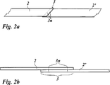
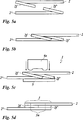
Erfindungsgemäß wird diese Aufgabe mit einem Verfahren zum Verbinden einer ersten und einer zweiten Folienbahn einer Transferfolie oder Laminierfolie gelöst, wobei die Folienbahnen eine thermoplastische Trägerfolie und eine Dekorlage umfassen, und wobei vorgesehen ist, dass zwischen der ersten und der zweiten Folienbahn ein gemeinsamer Verbindungsabschnitt ausgebildet wird, in dem die erste und die zweite Folienbahn durch ein Schweißverfahren miteinander verbunden werden.According to the invention, this object is achieved by a method for joining a first and a second film web of a transfer film or laminating film, wherein the film webs comprise a thermoplastic carrier film and a decorative layer, and it is provided that a common connecting section is formed between the first and the second film web in which the first and the second film web are joined together by a welding process.
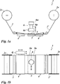
Die Aufgabe wird werter mit einer Vorrichtung zum stoffschlüssigen Verbinden einer ersten und einer zweiten Folienbahn einer Transferfolie oder Laminierfolie gelöst, wobei die Folienbahnen eine thermoplastische Trägerfolie und eine Dekorlage umfassen, und wobei die Dekorlage Motive und/oder Passmarken aufweist, und wobei vorgesehen ist, dass die Vorrichtung Aufnahmevorrichtungen für die erste und die zweiten Folienbahn und mindestens einen Schweißkopf umfasst, der über einem Verbindungsabschnitt der ersten und der zweiten Folienbahn angeordnet ist, und dass mindestens eine der Aufnahmevorrichtungen mit einer Justiereinrichtung bewegungsstarr verbunden ist.The object is achieved by a device for materially joining a first and a second film web of a transfer film or laminating film, wherein the film webs comprise a thermoplastic carrier film and a decorative layer, and wherein the decorative layer has motifs and / or registration marks, and it is provided that the device comprises receiving devices for the first and the second film web and at least one welding head, which is arranged above a connecting portion of the first and the second film web, and that at least one of the receiving devices is connected to an adjusting device in a manner of freezing motion.
Überraschender Weise hat sich gezeigt, dass eine dauerhafte und belastbare Schweißverbindung eintritt, obwohl die zu verschweißenden Folienbahnen als Mehrschichtkörper ausgebildet sind, die neben der verschweißbaren thermoplastischen Trägerfolie weitere Schichten umfassen, die die Festigkeit der Schweißverbindung herabsetzen können oder diese verhindern können.Surprisingly, it has been found that a durable and strong welded joint occurs, although the film webs to be welded are formed as a multi-layer body, which in addition to the heat-sealable thermoplastic support film further layers that can reduce the strength of the weld or prevent it.
Zudem weisen die Folien nach dem Schweißen eine sehr gute Planlage ohne nachteilige Verdickungsstelle durch ein zusätzliches Klebeband im Bereich der Naht auf und zeigen praktisch keine Dimensionsänderungen, insbesondere ein- oder zweidimensionale Verzüge, was zum Beispiel für Folgeprozesse wie Schneid- und Konfektionierungsprozesse von großer Bedeutung ist.In addition, the films have a very good flatness after welding without disadvantageous thickening by an additional adhesive tape in the seam and show virtually no dimensional changes, especially one or two-dimensional distortions, which is for example for subsequent processes such as cutting and packaging processes of great importance ,
Bei den Transferfolien handelt es sich um Folien, deren Dekorlage durch ein Prägewerkzeug mittels Druck und/oder Temperatur auf ein zu dekorierendes Substrat übertragen wird. Die Basis der Transferfolie bildet eine Trägerfolie aus einem thermoplastischen Kunststoff, auf der eine ablösbare Dekorlage angeordnet ist.The transfer films are films whose decorative layer is transferred by means of an embossing tool by means of pressure and / or temperature to a substrate to be decorated. The base of the transfer film forms a carrier film of a thermoplastic material, on which a removable decorative layer is arranged.
Die Dekorlage kann neben einer oder mehreren, das Dekor tragenden Dekorschichten weitere Schichten umfassen, beispielsweise eine Kleberschicht, eine Aktivierungsschicht für die Kleberschicht und eine Trennschicht, um das Ablösen der Dekorlage von einer Trägerfolie zu erleichtern.The decorative layer can comprise, in addition to one or more decorative layers carrying the decor, further layers, for example an adhesive layer, an activation layer for the adhesive layer and a release layer to facilitate detachment of the decorative layer from a carrier film.
Die eine Dekorschicht oder die mehreren Dekorschichten können beispielsweise jeweils als eine optional eingefärbte, transparente, transluzente oder opake Lackschicht, als eine fluoreszierende oder phosphoreszierende Lackschicht, als eine optisch variable Schicht und/oder als eine metallische oder nichtmetallische Reflexionsschicht ausgebildet sein. So kann eine Dekorschicht als eine pigmentierte Lackschicht ausgebildet sein, so dass Farbwirkungen ausbildbar sind und Bilder sowie alphanumerische Zeichen oder Symbole darstellbar sind. Die Dekorschicht kann eine funktionale Schicht, beispielsweise eine Magnetschicht, eine Photopolymerschicht oder eine Schicht aus leitenden, halbleitenden oder nichtleitenden Polymeren sein. Folien mit derartigen Dekorschichten können im Bereich von Magnetfolien, zum Fälschungsschutz von Banknoten und Dokumenten, für Außenanwendungen, zum Beispiel Chromfolien für Nummernschilder oder andere Dekore, im Bereich der IMD- oder IML-Technologie(IMD = In Mould Decoration; IML = In Mould-Labeling), für Antennenanwendungen sowie für Label unterschiedlichster Anwendungen zum Einsatz kommen. Zudem sind Kombinationen der genannten Dekorschichten ausführbar, wobei in einer Dekorschicht unterschiedliche Schichten direkt oder indirekt nebeneinander vorliegen. Die Schichtdicke einer solchen Dekorschicht beträgt vorzugsweise zwischen 1 μm und 25 μm, weiter bevorzugt zwischen 1 μm und 5 μm. Eine optisch variable Schicht kann von einer Replizierlackschicht mit einem abgeformten, diffraktiv und/oder refraktiv wirkenden Oberflächenrelief, einer Hologrammschicht, einer Volumenhologrammschicht, einem Dünnfilmschichtsystem, welches Farbwechseleffekte mittels Interferenz erzeugt, einer Flüssigkristallschicht oder einer Pigmente enthaltenden Schicht gebildet sein, beispielsweise optisch variable Interferenzschichtpigmente oder optisch variable Flüssigkristallpigmente oder Metall- oder Metalloxidpigmente. Als Oberflächenrelief kann beispielsweise eine refraktiv wirkende Makrostruktur, beispielsweise eine Linsenstruktur, ein diffraktives Beugungsgitter oder ein Hologramm abgeformt sein, welches vorzugsweise mit einer Reflektionsschicht belegt ist. Zur Unterstützung der optischen Effekte können metallische Schichten vorgesehen sein, die einfallendes Licht zurückwerfen. Die Dekorschichten können bereichsweise unterschiedlich ausgebildet sein und beliebig miteinander kombiniert sein, so dass beispielsweise OVD-Bereiche (Optically Variable Device) und Bildbereiche nebeneinander oder überlagernd dargestellt sind.The one or more decorative layers may be formed, for example, in each case as an optionally colored, transparent, translucent or opaque lacquer layer, as a fluorescent or phosphorescent lacquer layer, as an optically variable layer and / or as a metallic or non-metallic reflection layer. Thus, a decorative layer may be formed as a pigmented lacquer layer, so that color effects can be formed and images and alphanumeric characters or symbols can be displayed. The decorative layer may be a functional layer, for example a magnetic layer, a photopolymer layer or a layer of conductive, semiconductive or non-conductive polymers. Films with such decorative layers can be used in the field of magnetic foils, for counterfeit protection of banknotes and documents, for outdoor applications, for example chrome foils for number plates or other decors, in the area of IMD or IML technology (IMD = In Mold Decoration; Labeling), for antenna applications as well as for labels of various applications. In addition, combinations of said decorative layers can be carried out, wherein in a decorative layer different layers are present directly or indirectly next to each other. The layer thickness of such a decorative layer is preferably between 1 .mu.m and 25 .mu.m, more preferably between 1 .mu.m and 5 .mu.m. An optically variable layer may be formed by a replicating lacquer layer having a molded, diffractive and / or refractive surface relief, a hologram layer, a volume hologram layer, a thin film layer system which generates color change effects by interference, a liquid crystal layer or a pigment containing layer, for example optically variable interference layer pigments or optically variable liquid crystal pigments or metal or metal oxide pigments. As a surface relief, for example, a refractive macrostructure, for example a lens structure, a diffractive diffraction grating or a hologram may be formed, which is preferably covered with a reflective layer. To assist the optical effects, metallic layers can be provided which reflect back incident light. The decorative layers may be formed differently in regions and combined with each other arbitrarily, so that, for example, OVD regions (optically variable device) and image regions are shown side by side or superimposed.
Bei Laminierfolien ist eine Trennung der Dekorlage von der Trägerfolie nicht vorgesehen. Zwischen der Dekorlage und der Trägerfolie kann daher eine Haftvermittlerschicht vorgesehen sein. Die Dekorlage kann neben einer oder mehreren Dekorschichten weiter eine Kleberschicht umfassen. Es kann sich dabei um eine Heißkleberschicht oder eine Kaltkleberschicht handeln. Die Dekorschichten können wie die Dekorschichten der Transferfolie ausgebildet sein.When laminating a separation of the decorative layer is not provided by the carrier film. An adhesive layer may therefore be provided between the decorative layer and the carrier film. The decorative layer may further include an adhesive layer in addition to one or more decorative layers. It may be a hot melt adhesive layer or a cold adhesive layer. The decorative layers may be formed like the decorative layers of the transfer film.
Die einzelnen Schichten des Folienaufbaus können aus thermoplastischem Material, duroplastischem Material, zum Beispiel aus Lacken, die mittels UV-Strahlung vernetzt werden können, sowie aus Hybridmaterial (thermoplastisch, d. h. thermisch trocknend und gleichzeitig mit Strahlung vernetzbar) oder Kombinationen davon bestehen.The individual layers of the film structure can be made of thermoplastic material, thermosetting material, for example, paints, which can be crosslinked by means of UV radiation, as well as of hybrid material (thermoplastic, ie thermal drying and crosslinkable at the same time with radiation) or combinations thereof.
Die Schichtabfolgen können auch mehrfach vorliegen. Möglich ist auch, dass eine Dekorlage aus funktionalen und/oder dekorativen Schichten auf beiden Seiten der Trägerfolie vorliegt.The sequence of layers can also be multiple. It is also possible that a decorative layer of functional and / or decorative layers is present on both sides of the carrier film.
Insbesondere von den Trennschichten, bei denen es sich vorzugsweise um Wachstrennschichten handelt, welche bei Aktivierung mittels Wärme beim Heißprägen erweicht werden und dadurch ihre Trennfunktion erfüllen, und von den Metallisierungsschichten war zu erwarten, dass sie die Festigkeit der Schweißverbindung so stark herabsetzen, dass eine sichere Verbindung zweier Folienbahnen nicht möglich ist.In particular, the release layers, which are preferably wax release layers, which soften upon hot activation heat softening and thereby perform their separation function, and of the metallization layers were expected to reduce the strength of the weld so much that a safe Connection of two film webs is not possible.
Mit dem erfindungsgemäßen Verfahren und der erfindungsgemäßen Vorrichtung können überraschenderweise dennoch Folien mit hoher Genauigkeit durch eine Schweißverbindung gespleißt werden, wobei ein Verbindungsabschnitt ausgebildet wird, der im Rolle-zu-Rolle-Prozess zu keiner Produktionsstörung führt.Surprisingly, with the method according to the invention and the device according to the invention, nevertheless, films can be spliced with high accuracy through a welded connection, whereby a connecting section is formed which leads to no production disturbance in the roll-to-roll process.
Es kann vorgesehen sein, dass der gemeinsame Verbindungsabschnitt als ein Überlappungsstoß ausgebildet wird. Der Überlappungsstoß kann mit besonders geringer Breite ausgebildet werden, so dass auch Folien spleißbar sind, deren Motivabstand innerhalb des Layouts der Motive so gering ist, dass bei Verwendung von Spleißband die dem Verbindungsabschnitt benachbarten Motive nicht abprägbar wären.It can be provided that the common connecting portion is formed as a lap joint. The overlap impact can be formed with a particularly small width, so that films can also be spliced whose motif distance within the layout of the motifs is so small that, when using splicing tape, the motifs adjacent to the connection section would not be printable.
Es kann auch vorgesehen sein, dass der gemeinsame Verbindungsabschnitt als ein Stumpfstoß, der von einer Spleißfolie überdeckt ist, ausgebildet wird. Bei der Spleißfolie handelt es sich allerdings nicht um ein Klebeband, so dass Verschmutzungen durch Austritt von Kleber nicht auftreten können. Die Spleißfolie kann auch eine geringere Dicke als ein Klebeband aufweisen, insbesondere eine Dicke von etwa 5 μm bis 20 μm aufweisen.It can also be provided that the common connecting portion is formed as a butt joint which is covered by a splicing foil. However, the splicing film is not an adhesive tape, so that contamination by leakage of adhesive can not occur. The splicing film may also have a smaller thickness than an adhesive tape, in particular have a thickness of about 5 microns to 20 microns.
Es kann weiter vorgesehen sein, dass die erste und die zweite Folienbahn mittels Ultraschallschweißen miteinander verbunden werden.It may further be provided that the first and the second film web are joined together by means of ultrasonic welding.
In einer weiteren Ausführung kann vorgesehen sein, dass die erste und die zweite Folienbahn mittels Kontaktschweißen miteinander verbunden werden. Beim Kontaktschweißen werden erhitzte Abschnitte des Schweißkopfes mit dem Verbindungsabschnitt in thermischen Kontakt gebracht, so dass ein lokales Aufschmelzen der beiden Folienbahnen erfolgt, die dadurch miteinander verschweißt werden.In a further embodiment it can be provided that the first and the second film web are connected to one another by means of contact welding. In contact welding heated portions of the welding head are brought into thermal contact with the connecting portion, so that there is a local melting of the two film webs, which are thereby welded together.
Es kann vorgesehen sein, dass zur Ausbildung einer Schweißnaht ein erhitztes Band oder ein erhitzter Draht verwendet wird.It can be provided that a heated strip or a heated wire is used to form a weld.
Weiter kann vorgesehen sein, dass die erste und die zweite Folienbahn mittels Laserschweißen miteinander verbunden werden. Es kann vorgesehen sein, einen Laser längs der Schweißnaht zu bewegen und/oder das Laserlicht optisch so abzulenken, dass es eine Linie ausbildet.It can further be provided that the first and the second film web are connected to one another by means of laser welding. It can be provided to move a laser along the weld and / or to optically deflect the laser light so that it forms a line.
Es kann vorgehen sein, dass in dem Verbindungsabschnitt unter der ersten und der zweiten Folienbahn eine Absorptionsschicht für Laserlicht angeordnet wird. Die Absorptionsschicht wandelt das Laserlicht in Wärme um. Dadurch ist es insbesondere möglich, geringere Laserleistungen zu verwenden. Durch die Absorptionsschicht ist es außerdem möglich, die auf die Schweißstelle einwirkende Energie auch rückseitig in die Schweißstelle einzutragen, d. h. von der dem Laserlicht abgewandten Seite. Die Absorptionsschicht kann als oberste Schicht oder unter einer anderen Schicht innerhalb einer mehrschichtigen Dekorlage angeordnet sein. Möglich ist auch der Einsatz mehrerer Absorptionsschichten, ggf. an unterschiedlichen Positionen innerhalb der Dekorlage und mit ggf. unterschiedlicher Absorptionscharakteristik für Laserlicht.It may be possible for an absorption layer for laser light to be arranged in the connecting section below the first and the second film web. The absorption layer converts the laser light into heat. This makes it possible in particular to use lower laser powers. Through the absorption layer, it is also possible to enter the energy acting on the weld also back of the weld, d. H. from the side facing away from the laser light. The absorption layer may be arranged as the uppermost layer or under another layer within a multilayer decorative layer. It is also possible to use a plurality of absorption layers, possibly at different positions within the decorative layer and possibly with different absorption characteristics for laser light.
In einer vorteilhaften Ausbildung kann vorgesehen sein, dass als Absorptionsschicht eine das Laserlicht absorbierende Spleißfolie verwendet wird. Bei der Spleißfolie handelt es sich allerdings nicht um ein Klebeband, so dass Verschmutzungen durch Austritt von Kleber nicht auftreten können. Vorteilhafterweise kann es sich um eine eingefärbte Folie aus dem Material der Trägerfolie handeln.In an advantageous embodiment, it may be provided that a splicing foil which absorbs the laser light is used as the absorption layer. However, the splicing film is not an adhesive tape, so that contamination by leakage of adhesive can not occur. Advantageously, it may be a colored film of the material of the carrier film.
Die Schnittkanten der Folien können geradlinig ausgebildet sein. Möglich ist auch der Einsatz von wellenförmig geschnittenen, perforierten, gezackten Kanten usw.The cut edges of the films may be rectilinear. It is also possible to use wavy-cut, perforated, serrated edges, etc.
Es kann vorgesehen sein, dass eine kontinuierliche Schweißnaht ausgebildet wird. In der einfachsten Form kann es sich um eine geradlinige kontinuierliche Einfach- oder Mehrfachnaht handeln. Die kontinuierliche Schweißnaht kann auch wellenförmig, gezackt oder mäanderförmig ausgebildet sein. Der Schweißkopf, beispielsweise der Kontaktschweißkopf, der Laserstrahl oder die Sonotrode, kann der genannten Nahtkontur entsprechend über die Folienoberfläche bewegt werden oder es kann ein entsprechend ausgeformter Schweißdraht vorgesehen sein.It can be provided that a continuous weld is formed. In the simplest form, it may be a straight continuous single or multiple seam. The continuous weld can also be wave-shaped, serrated or meander-shaped. The welding head, for example the contact welding head, the laser beam or the sonotrode, can be moved over the film surface correspondingly to said seam contour or a correspondingly shaped welding wire can be provided.
Es kann auch vorgesehen sein, dass eine diskontinuierliche Schweißnaht ausgebildet wird. So können insbesondere gestrichelte oder gepunktete Schweißnähte ausgebildet werden, indem beispielsweise der Laserstrahl ein- und ausgeschaltet wird, der Kontaktschweißkopf oder die Sonotrode ein- und ausgeschaltet oder von der Folienoberfläche abgehoben und wieder aufgesetzt wird.It can also be provided that a discontinuous weld seam is formed. In particular, dashed or dotted weld seams can be formed by, for example, switching the laser beam on and off, the contact welding head or the sonotrode is switched on and off or lifted off the film surface and put back on.
Weiter kann vorgesehen sein, dass eine Schweißnaht in oszillierender Form ausgebildet wird. Bei einer oszillierenden Schweißnaht kann die Lage der Schweißnaht und/oder die Breite der Schweißnaht variiert sein. Es kann beispielsweise der Fokus des Laserstrahls verändert werden. Weiter kann vorgesehen sein, Kontaktschweißköpfe oder Sonotroden mit länglichem Querschnitt, beispielsweise rechteckförmigem oder elliptischen Querschnitt zu verwenden und diese um ihre Längsachse zu drehen oder zu schwenken. Die Breite der Schweißnaht kann bei dieser Ausbildung variiert werden, indem durch die Drehlage des Schweißkopfes unterschiedlich effektive Breiten des Schweißkopfes eingestellt werden. Die effektive Breite des Schweißkopfes variiert so zwischen der Abmessung der Schmalseite des Rechtecks oder der Ellipse und der Abmessung der Breitseite des Rechtecks oder der Ellipse.It can further be provided that a weld seam is formed in an oscillating shape. In an oscillating weld, the position of the weld and / or the width of the weld may be varied. For example, the focus of the laser beam can be changed. It can further be provided to use contact welding heads or sonotrodes with an oblong cross section, for example a rectangular or elliptical cross section, and to turn or pivot them about their longitudinal axis. The width of the weld can be varied in this design by different effective widths of the welding head can be adjusted by the rotational position of the welding head. The effective width of the welding head thus varies between the dimension of the narrow side of the rectangle or the ellipse and the dimension of the broad side of the rectangle or the ellipse.
In einer weiteren vorteilhaften Ausbildung kann vorgesehen sein, dass die Dekorlage vor dem Schweißprozess im Bereich der Schweißnaht entfernt wird. Das Entfernen der Dekorlage kann durch in Kontakt bringen mit einem selbstklebenden Klebeband mit nachfolgendem Abziehen der Dekorlagen oder durch vorgängiges Transferieren auf eine Unterlage mittels eines zum Beispiel 3 mm breiten beheizten Prägerades erfolgen.In a further advantageous embodiment it can be provided that the decorative layer is removed before the welding process in the region of the weld. The removal of the decorative layer can be done by bringing into contact with a self-adhesive tape with subsequent removal of the decorative layers or by prior transfer to a pad by means of, for example, a 3 mm wide heated embossing wheel.
Möglich ist auch die vorgängige Modifikation, insbesondere Ablation oder thermische Zerstörung, der Dekorlage mittels Lasereinwirkung.Also possible is the previous modification, in particular ablation or thermal destruction, the decorative layer by means of laser action.
Weiter kann vorgesehen sein, dass die erste und die zweite Folienbahn so zueinander ausgerichtet werden, dass die auf der ersten Folienbahn angeordneten Motive und/oder Passmarken zu den auf der zweiten Folienbahn angeordneten Motive und/oder Passmarken im Verbindungsabschnitt im Register mit einer Lagetoleranz kleiner als +/–0,5 mm ausgerichtet sind. Wenn die Motive klare Konturen aufweisen, beispielsweise scharte Kanten und/oder Konturen, können Passmarken entbehrlich sein.It can further be provided that the first and the second film web are aligned with one another in such a way that the motifs and / or registration marks arranged on the first film web are smaller than the motifs and / or registration marks arranged in the second film web in the connecting section in the register +/- 0.5 mm are aligned. If the subjects have clear contours, such as sharp edges and / or contours, registration marks can be dispensable.
Weitere Ansprüche sind auf die Ausbildung der Vorrichtung gerichtet.Further claims are directed to the formation of the device.
Es kann vorgesehen sein, dass die Justiereinrichtung so ausgebildet ist, dass die auf der ersten Folienbahn angeordnete Motive und/oder Passmarken zu den auf der zweiten Folienbahn angeordneten Motive und/oder Passmarken in dem Verbindungsabschnitt im Register mit einer Lagetoleranz kleiner als +/–0,5 mm ausrichtbar sind oder umgekehrt. Die Justiereinrichtung kann eine oder mehrere Messeinrichtungen und einen oder mehrere Antriebseinrichtungen umfassen. Die Antriebseinrichtungen können beispielsweise in die Aufnahmevorrichtung integriert sein. Es kann sich dabei um Linearmotoren handeln, wobei die Aufnahmevorrichtung einen Kreuztisch umfassen kann, der in x- und y-Richtung durch die Linearmotoren bewegbar ist. Die Messeinrichtung kann beispielsweise eine elektronische Kamera und einen Computer mit Bilderfassungs- und verarbeitungssoftware umfassen.It can be provided that the adjusting device is designed so that the arranged on the first film web motifs and / or registration marks to the arranged on the second film web motifs and / or registration marks in the connecting portion in the register with a position tolerance less than +/- 0 , 5 mm are alignable or vice versa. The adjusting device may comprise one or more measuring devices and one or more drive devices. The drive devices can be integrated, for example, in the receiving device. It may be linear motors, wherein the receiving device may comprise a cross table, which is movable in the x and y direction by the linear motors. The measuring device may comprise, for example, an electronic camera and a computer with image acquisition and processing software.
Es kann vorgesehen sein, dass der mindestens eine Schweißkopf senkrecht zu der Oberfläche der Folienabschnitte bewegbar ist.It can be provided that the at least one welding head is movable perpendicular to the surface of the film sections.
Weiter kann vorgesehen sein, dass der mindestens eine Schweißkopf um seine Längsachse drehbar ist, wie weiter oben beschrieben.It can further be provided that the at least one welding head is rotatable about its longitudinal axis, as described above.
Weiter kann vorgesehen sein, dass der mindestens eine Schweißkopf quer zu der Oberfläche der Folienabschnitte in x- und/oder y-Richtung, insbesondere frei bewegbar ist. Diese Option kann bevorzugt sein, wenn Folienbahnen gespleißt werden, deren Breite größer als die Arbeitsbreite des Schweißkopfes ist.It can further be provided that the at least one welding head is movable transversely to the surface of the film sections in the x and / or y direction, in particular freely. This option may be preferred when splicing film webs whose width is greater than the working width of the welding head.
Der Schweißkopf kann so ausgebildet sein, dass er Schweißnähte beliebiger Form und Muster sowie Ein- und Mehrfachschweißnähte erzeugen kann.The welding head can be designed so that it can produce welds of any shape and pattern as well as single and multiple welds.
Es kann vorgesehen sein, dass der mindestens eine Schweißkopf als ein Ulltraschallschweißkopf ausgebildet ist. Der Schweißkopf kann austauschbare Sonotroden aufweisen, beispielsweise um unterschiedliche Schweißnahtgeometrien ausbilden zu können.It can be provided that the at least one welding head is designed as a Ulltraschallschweißkopf. The welding head can have exchangeable sonotrodes, for example in order to be able to form different weld seam geometries.
Weiter kann vorgesehen sein, dass der mindestens eine Schweißkopf als ein Kontaktschweißkopf ausgebildet ist. Es kann ein Impulsbetrieb vorgesehen sein, um eine flächige Erwärmung des Schweißkopfes zu vermeiden.It can further be provided that the at least one welding head is designed as a contact welding head. It may be provided a pulse operation in order to avoid a surface heating of the welding head.
In einer weiteren vorteilhaften Ausbildung kann vorgesehen sein, dass der mindestens eine Schweißkopf als ein Laserschweißkopf ausgebildet ist. Die Schweißvorrichtung kann eine speziell ausgestaltete, insbesondere wenig haftende Unterlage (beispielsweise aus Metall, Silikon, Teflon, Polyamid oder ähnliches) aufweisen. Möglich ist auch eine beispielsweise zwischen Sonotrode und Folienoberfläche angeordnete Auflage, zum Beispiel in Form einer Silikonauflage. Die Schweißvorrichtung kann weiter Einrichtungen zum Schneiden und/oder Fixieren der Folien haben. Beispiele sind Ansaugvorrichtungen, Klemm- und Spannvorrichtungen, Anpressvorrichtungen oder Kombinationen davon.In a further advantageous embodiment it can be provided that the at least one welding head is designed as a laser welding head. The welding device may have a specially configured, in particular low-adhesion pad (for example made of metal, silicone, Teflon, polyamide or the like). It is also possible, for example, in the form of a silicone support arranged between sonotrode and film surface pad. The welding device may further have means for cutting and / or fixing the films. Examples are suction devices, clamping and tensioning devices, pressure devices or combinations thereof.
Die Erfindung wird nun anhand von Ausführungsbeispielen näher erläutert. Es zeigen The invention will now be explained in more detail with reference to exemplary embodiments. Show it
Die bandförmigen Folienbahnen
Die Aufnahmevorrichtung
Zu dem Ultraschallwandler
Die Sonotrode
Der abgesenkte Ultraschallschweißkopf
Überraschender Weise hat sich gezeigt, dass eine dauerhafte und belastbare Schweißverbindung eintritt, obwohl zwischen den beiden Trägerfolien im Überlappungsstoß
Alternativ zu der Doppelnaht aus zwei geradlinigen parallelen Einzelnähten sind auch andere Doppelnähte ausführbar, wenn der Ultraschallschweißkopf
Die
Die
Die
Die
Die
Ist der Kontaktschweißkopf
Die
Die beiden Folienbahnen
Wie Untersuchungen gezeigt haben, sind in den Schweißnähten
Wie Versuche mit unterschiedlichen Schweißverfahren zeigten, wird zwar die Zugfestigkeit eines konventionellen Spleißes nicht erreicht, doch wird die an einen Spleiß zu stellende minimale Anforderung einer Zugfestigkeit größer 13 N/cm erreicht. Die Zugfestigkeit wurde jeweils mit einer Zwick-Prüfmaschine ermittelt.As tests with different welding methods have shown, although the tensile strength of a conventional splice is not achieved, the minimum splice requirement for a splice greater than 13 N / cm is achieved. The tensile strength was determined in each case with a Zwick testing machine.
Für eine Ultraschallschweißuerbindung ergaben sich für Folien aus PET bei einer Nahtbreite von 0,8 mm in Abhängigkeit von der Materialdicke folgende Zugfestigkeiten:
- – PET 19 μm: 21,5 N/cm
- – PET 50 μm: 47,0 N/cm
- PET 19 μm: 21.5 N / cm
- PET 50 μm: 47.0 N / cm
Das Ausgangsmaterial weist bei einer Dicke von 19 μm eine Zugfestigkeit von 40–45 N/cm auf.The starting material has a tensile strength of 40-45 N / cm at a thickness of 19 microns.
Herkömmliches, mit Kleber beschichtetes Spleißband weist eine Zugfestigkeit von 30–40 N/cm auf. Bei einem konventionellen Spleiß und einer PET-Folie von 19 μm Dicke wird eine Zugfestigkeit von 35–45 N/cm erreicht.Conventional adhesive coated splice tape has a tensile strength of 30-40 N / cm. In a conventional splice and a PET film of 19 microns thickness, a tensile strength of 35-45 N / cm is achieved.
Der erfindungsgemäß geschweißte Spleiß des o. g. PET-Materials wies eine Zugfestigkeit von 15–25 N/cm auf, was für die Weiterverarbeitung der verbundenen Folienbahnen in einem Rolle-zu-Rolle-Verfahren ausreichend ist.The inventively welded splice of o. G. PET material had a tensile strength of 15-25 N / cm, which is sufficient for further processing of the bonded film webs in a roll-to-roll process.
In einem weiteren Versuch wurde Folienbahnen einer Heißprägefolie durch Ultraschallschweißen mit einer Nahtbreite von 0,6–1,0 mm verbunden, wobei die Zugfestigkeit pro Naht 12–19 N/cm betrug.In a further experiment, film webs of a hot stamping film were bonded by ultrasonic welding with a seam width of 0.6-1.0 mm, the tensile strength per seam being 12-19 N / cm.
Mit einer Heißprägefolie mit pigmentiertem Kleber wurde bei gleicher Nahtbreite von 0,6–1,0 mm nur eine Zugfestigkeit von 3,0 N/cm pro Naht erreicht.With a hot stamping foil with pigmented adhesive, only a tensile strength of 3.0 N / cm per seam was achieved with the same seam width of 0.6-1.0 mm.
Weitere Versuche wurden durchgeführt, um den Einfluss der Nahtbreite und des Schweißverfahrens zu ermitteln:
- – Ultraschallschweißen (pro 0,5 mm Naht): 4,1 N/cm
- – Ultraschallschweißen (pro 1 mm Naht): 8,5 N/cm
- – Impulsschweißen bzw. Kontaktschweißen (pro 1,6 mm Naht): 12,8 N/cm
- - Ultrasonic welding (per 0.5 mm seam): 4.1 N / cm
- - Ultrasonic welding (per 1 mm seam): 8.5 N / cm
- - Impulse welding or contact welding (per 1.6 mm seam): 12.8 N / cm
Offensichtlich hat die Breite der Schweißnaht den entscheidenden Einfluss auf die Zugfestigkeit der Schweißnaht.Obviously, the width of the weld has a decisive influence on the tensile strength of the weld.
Es wurden folgende Anforderungen an die Nahtstelle der beiden Folienbahnen
Wie sich weiter zeigte, konnten folgende Ergebnisse beim Verbinden von Folienbahnen einer Heißprägefolie mit einer Gesamtdicke von etwa 19 μm erreicht werden:
- – Herstellung einer Nahtstelle im Register mit +/–0,5 mm Toleranz;
- – Breite der Nahtstelle maximal 3 mm;
- – Auftragen der Nahtstelle, das heißt Dicke der Nahtstelle nicht größer als bei Ausbildung mit Spleißband;
- – Haftung so gut, dass die Folie die in einer typischen Applikationsmaschine auftretenden Zugkräfte übersteht;
- – Länge der Nahtstelle:
im Bereich von 10 bis 650 mm,
As further shown, the following results could be achieved when joining foil webs of a hot stamping foil with a total thickness of about 19 μm:
- - Creation of a seam in the register with +/- 0.5 mm tolerance;
- - width of the seam maximum 3 mm;
- - Application of the interface, that is thickness of the interface not larger than when trained with splice tape;
- Adhesion so good that the film will withstand the tensile forces occurring in a typical application machine;
- - length of the interface: in the range of 10 to 650 mm,
BezugszeichenlisteLIST OF REFERENCE NUMBERS
- 11
- Vorrichtung zum Verbinden von FolienabschnittenDevice for joining foil sections
- 2, 2'2, 2 '
- Folienabschnittfilm section
- 2f, 2f'2f, 2f '
- Faltabschnittfolding section
- 2v2v
- Vorratsrollesupply roll
- 33
- Überlappungsstoßlap joint
- 3n3n
- SchweißnahtWeld
- 4, 4'4, 4 '
- Aufnahmevorrichtungcradle
- 4j4y
- Justiereinrichtungadjusting
- 55
- Ambossanvil
- 66
- UltraschallschweißkopfUltrasonic welding head
- 6a6a
- AmplitudentransformationsstückAmplitude transformation piece
- 6s6s
- Sonotrodesonotrode
- 6w6w
- Ultraschallwandlerultrasound transducer
- 77
- SpleißfolieSpleißfolie
- 88th
- KontaktschweißkopfContact welding head
- 8h8h
- Heizelementheating element
- 99
- LaserschweißkopfLaser welding head
- 1010
- Absorptionsschichtabsorbing layer
- 2121
- Trägerfoliesupport film
- 2222
- TrennschichtInterface
- 2323
- Übertragungslagetransfer layer
- 2424
- Metallisierungmetallization
Claims (22)
Priority Applications (10)
| Application Number | Priority Date | Filing Date | Title |
|---|---|---|---|
| DE102011111786A DE102011111786A1 (en) | 2011-09-01 | 2011-09-01 | Method and apparatus for joining transfer or laminating film webs |
| JP2014527560A JP6090324B2 (en) | 2011-09-01 | 2012-07-31 | Method and apparatus for joining transfer film webs or laminated film webs |
| EP12745449.4A EP2750864B1 (en) | 2011-09-01 | 2012-07-31 | Method for joining transfer or laminating film webs |
| MX2014002189A MX350755B (en) | 2011-09-01 | 2012-07-31 | Method and device for joining transfer or laminating film webs. |
| RU2014112354A RU2606648C2 (en) | 2011-09-01 | 2012-07-31 | Method and device for connection of image transferring or lamination film webs |
| US14/342,090 US9782927B2 (en) | 2011-09-01 | 2012-07-31 | Method and device for joining transfer or laminating film webs |
| TR2019/02068T TR201902068T4 (en) | 2011-09-01 | 2012-07-31 | Method for joining transfer or lamination film strips. |
| PCT/EP2012/064913 WO2013029901A1 (en) | 2011-09-01 | 2012-07-31 | Method and device for joining transfer or laminating film webs |
| CN201280048512.4A CN103842154B (en) | 2011-09-01 | 2012-07-31 | Method and apparatus for connecting transfer film web or laminate film web |
| BR112014004633-6A BR112014004633B1 (en) | 2011-09-01 | 2012-07-31 | method for joining transfer film or laminating blankets |
Applications Claiming Priority (1)
| Application Number | Priority Date | Filing Date | Title |
|---|---|---|---|
| DE102011111786A DE102011111786A1 (en) | 2011-09-01 | 2011-09-01 | Method and apparatus for joining transfer or laminating film webs |
Publications (1)
| Publication Number | Publication Date |
|---|---|
| DE102011111786A1 true DE102011111786A1 (en) | 2013-03-07 |
Family
ID=46640010
Family Applications (1)
| Application Number | Title | Priority Date | Filing Date |
|---|---|---|---|
| DE102011111786A Ceased DE102011111786A1 (en) | 2011-09-01 | 2011-09-01 | Method and apparatus for joining transfer or laminating film webs |
Country Status (10)
| Country | Link |
|---|---|
| US (1) | US9782927B2 (en) |
| EP (1) | EP2750864B1 (en) |
| JP (1) | JP6090324B2 (en) |
| CN (1) | CN103842154B (en) |
| BR (1) | BR112014004633B1 (en) |
| DE (1) | DE102011111786A1 (en) |
| MX (1) | MX350755B (en) |
| RU (1) | RU2606648C2 (en) |
| TR (1) | TR201902068T4 (en) |
| WO (1) | WO2013029901A1 (en) |
Cited By (4)
| Publication number | Priority date | Publication date | Assignee | Title |
|---|---|---|---|---|
| DE102013214553A1 (en) * | 2013-07-25 | 2015-01-29 | Bayerische Motoren Werke Aktiengesellschaft | Method for sealing a side region of a film stack, film stack and laminated glass pane |
| US20150174687A1 (en) * | 2013-12-23 | 2015-06-25 | Samsung Display Co., Ltd. | Method for fusing nanowire junctions in conductive films |
| FR3041950A1 (en) * | 2015-10-01 | 2017-04-07 | C E R M E X Constructions Etudes Et Rech De Materiels Pour L'emballage D'expedition | FEEDING FOR FARDELING |
| DE102018130674A1 (en) * | 2018-12-03 | 2020-06-04 | Bundesdruckerei Gmbh | Method and device for splicing a first and a second film composite |
Families Citing this family (26)
| Publication number | Priority date | Publication date | Assignee | Title |
|---|---|---|---|---|
| EP2873517B1 (en) * | 2013-11-14 | 2019-04-24 | Airbus Defence and Space GmbH | Stabilising device, stabilising process and method for producing fibre compound components |
| ES2777299T3 (en) * | 2014-05-12 | 2020-08-04 | Tetra Laval Holdings & Finance | Splicing device and method |
| KR101602815B1 (en) * | 2014-07-28 | 2016-03-21 | 신화인터텍 주식회사 | Soft mold for optical film and method of fabricating the same |
| FR3033515B1 (en) * | 2015-03-12 | 2017-11-24 | Spoolex | ULTRASOUND PERFECTION LAMINATING METHOD OF A THERMOFUSIBLE ARTICLE, AND ROLLING DEVICE FOR CARRYING OUT SAID METHOD |
| EP3081515B1 (en) * | 2015-03-19 | 2019-05-08 | Domenico Reviati | Method and system for continuous change of reels made of corrugated cardboard, supplying packaging machines and packaging machine comprising such a system |
| US10351377B2 (en) | 2015-08-03 | 2019-07-16 | Elsner Engineering Works, Inc. | Ultrasonic roll tail closure of non-woven web material method and apparatus |
| TWI764875B (en) * | 2015-11-03 | 2022-05-21 | 德商利昂哈德 庫爾茲公司 | Method for applying a transfer layer on a film to a substrate and an application device therefor |
| SI3383203T1 (en) * | 2015-12-02 | 2020-08-31 | Swedish Match North Europe Ab | An oral pouched snuff product |
| JP6715928B2 (en) * | 2016-07-01 | 2020-07-01 | エステー産業株式会社 | Sheet welding equipment |
| CN108687442B (en) * | 2017-03-30 | 2021-10-01 | 法拉第未来公司 | System and method for welding |
| JP6842669B2 (en) * | 2017-05-29 | 2021-03-17 | トヨタ紡織株式会社 | Particle impregnation device and manufacturing method of particle impregnated non-woven fabric |
| US10071439B1 (en) * | 2017-09-27 | 2018-09-11 | Spirit Aerosystems, Inc. | Method and system of joining thick sheets of non-weldable material using ultrasonic joining |
| US10413993B2 (en) * | 2017-09-27 | 2019-09-17 | Spirit Aerosystems, Inc. | Method and system of joining thick sheets of non-weldable material using ultrasonic joining |
| CN107555222A (en) * | 2017-10-09 | 2018-01-09 | 江门市南天机械制造有限公司 | A kind of film material receiving |
| CN107932660A (en) * | 2017-11-22 | 2018-04-20 | 陈德宁 | A kind of ultrasonic wave connects rattan machine |
| US11198249B2 (en) | 2018-07-30 | 2021-12-14 | General Electric Company | Method of joining additively manufactured components |
| DE102018133676A1 (en) * | 2018-12-28 | 2020-07-02 | Airbus Operations Gmbh | Joining process as well as processing head and production machine for performing the process |
| JP6574911B1 (en) * | 2019-01-16 | 2019-09-11 | 大成ラミック株式会社 | Joint tape, packaging film coupling method and coupling apparatus using the same |
| CN110315684B (en) * | 2019-08-13 | 2021-06-01 | 东莞市艾尔玛科技有限公司 | Foil feeder for in-mold transfer printing process |
| KR102223220B1 (en) * | 2019-11-05 | 2021-03-05 | (주)동양산기 | Continuous feeder of foam sheet |
| CN112223759B (en) * | 2020-10-09 | 2022-03-25 | 山东亚新塑料包装有限公司 | Preparation method of plastic film |
| CN112976589B (en) * | 2021-02-23 | 2023-03-21 | 赣州欧翔电子有限公司 | Ultrasonic welding device and ultrasonic welding method thereof |
| US11407182B1 (en) * | 2021-08-11 | 2022-08-09 | Dukane Ias, Llc | Depth control of seal line penetration for rotary ultrasonic horn/anvil welding without mechanical stop |
| US11654637B2 (en) | 2021-08-11 | 2023-05-23 | Dukane Ias, Llc | Depth control of seal line penetration for rotary ultrasonic horn/anvil welding without mechanical stop |
| US11701736B2 (en) * | 2021-09-30 | 2023-07-18 | Wiegel Tool Works, Inc. | Systems and methods for making a composite thickness metal part |
| IT202100031250A1 (en) * | 2021-12-14 | 2023-06-14 | Gd Spa | Procedure for joining two sheets of packaging material |
Citations (3)
| Publication number | Priority date | Publication date | Assignee | Title |
|---|---|---|---|---|
| DE3524964A1 (en) * | 1985-07-12 | 1987-01-22 | Grecon Greten Gmbh & Co Kg | Process for joining an end of a film web to the start of a film web |
| DE60023528T2 (en) * | 1999-09-30 | 2006-07-20 | Newmat S.A. | A method of making a false ceiling or wallcovering with a heat-strained, printed polymeric material |
| EP2305452A1 (en) * | 2009-10-02 | 2011-04-06 | Kirson Industrial Reinforcements GmbH | Method for joining coated textiles, joint points and use of a device to carry out the method |
Family Cites Families (25)
| Publication number | Priority date | Publication date | Assignee | Title |
|---|---|---|---|---|
| US3278149A (en) | 1965-02-19 | 1966-10-11 | Aluminum Co Of America | Shelving assembly |
| JPS4420877Y1 (en) * | 1966-03-01 | 1969-09-05 | ||
| US4259399A (en) * | 1978-08-31 | 1981-03-31 | Burlington Industries, Inc. | Ultrasonic nonwoven bonding |
| JPH05246592A (en) | 1992-03-02 | 1993-09-24 | Yamakawa Kako:Kk | Film feeding device |
| US5827384A (en) * | 1997-07-18 | 1998-10-27 | The Procter & Gamble Company | Process for bonding webs |
| JP3204171B2 (en) | 1997-07-31 | 2001-09-04 | ブラザー工業株式会社 | Ultrasonic welding fusing equipment |
| EP1105286A4 (en) * | 1998-07-10 | 2002-07-10 | Edison Welding Inst | Simultaneous butt and lap joints |
| JP2000159400A (en) | 1998-11-24 | 2000-06-13 | Ykk Corp | Tape end positioning device for tape end joiner |
| JP2000272013A (en) | 1999-03-23 | 2000-10-03 | Shin Etsu Polymer Co Ltd | Method for connecting plastic sheet material |
| WO2000066345A2 (en) | 1999-04-30 | 2000-11-09 | Powerlasers Ltd. | Method of clamping thermoplastic pieces and heat control for laser welding |
| JP2001001365A (en) | 1999-06-22 | 2001-01-09 | Dainippon Printing Co Ltd | Sheet unwinding feed apparatus for injection molding inmold decoration |
| JP2001158047A (en) | 1999-12-03 | 2001-06-12 | Panac Co Ltd | Method for ultrasonically welding and bonding synthetic resin film |
| JP4603122B2 (en) * | 2000-02-23 | 2010-12-22 | 四国化工機株式会社 | Ultrasonic sealing device |
| DK1184311T3 (en) * | 2000-08-31 | 2005-01-17 | Tetra Laval Holdings & Finance | Method of assembling laminated material for packaging of pourable foods |
| DE10226148B4 (en) | 2002-06-13 | 2011-11-17 | Tetra Laval Holdings & Finance S.A. | Device for bonding two packaging material webs |
| JP2004043072A (en) | 2002-07-10 | 2004-02-12 | Tokyo Autom Mach Works Ltd | Film splicing device |
| JP2004256268A (en) | 2003-02-27 | 2004-09-16 | Toppan Printing Co Ltd | Connecting method of web material |
| US7645353B2 (en) * | 2003-12-23 | 2010-01-12 | Kimberly-Clark Worldwide, Inc. | Ultrasonically laminated multi-ply fabrics |
| JP4420877B2 (en) | 2005-09-22 | 2010-02-24 | シャープ株式会社 | Image processing method, image processing apparatus, and image output apparatus |
| JP5008964B2 (en) | 2006-12-21 | 2012-08-22 | 芝浦メカトロニクス株式会社 | ACF tape bonding apparatus, ACF tape bonding apparatus, and ACF tape bonding method |
| DE102007038578A1 (en) * | 2007-08-16 | 2009-02-19 | Evonik Degussa Gmbh | Method of decorating surfaces |
| JP5342286B2 (en) | 2008-05-16 | 2013-11-13 | 日東電工株式会社 | Manufacturing method of sheet joined body and sheet joined body |
| CN101407112A (en) * | 2008-11-24 | 2009-04-15 | 四川蒙特工程建设有限公司 | Plastic film welding device |
| IT1392809B1 (en) | 2009-02-04 | 2012-03-23 | Goglio Spa | METHOD AND EQUIPMENT TO PERFORM HEAD JOINTS OF A THERMAL-HEATING AND LAMINATED FLEXIBLE LAMINATE SO IT HAS OBTAINED |
| IT1393913B1 (en) * | 2009-05-05 | 2012-05-17 | Rent Srl | GROUP AND PROCEDURE FOR FEEDING MATERIAL COILS IN SHEET, IN PARTICULAR BUT NOT ONLY THE PRINTED PLASTIC FILM WITH POSITION REFERENCES FOR AUTOMATIC PACKAGING MACHINES |
-
2011
- 2011-09-01 DE DE102011111786A patent/DE102011111786A1/en not_active Ceased
-
2012
- 2012-07-31 US US14/342,090 patent/US9782927B2/en not_active Expired - Fee Related
- 2012-07-31 EP EP12745449.4A patent/EP2750864B1/en not_active Not-in-force
- 2012-07-31 CN CN201280048512.4A patent/CN103842154B/en not_active Expired - Fee Related
- 2012-07-31 MX MX2014002189A patent/MX350755B/en active IP Right Grant
- 2012-07-31 RU RU2014112354A patent/RU2606648C2/en not_active IP Right Cessation
- 2012-07-31 WO PCT/EP2012/064913 patent/WO2013029901A1/en active Application Filing
- 2012-07-31 TR TR2019/02068T patent/TR201902068T4/en unknown
- 2012-07-31 JP JP2014527560A patent/JP6090324B2/en not_active Expired - Fee Related
- 2012-07-31 BR BR112014004633-6A patent/BR112014004633B1/en not_active IP Right Cessation
Patent Citations (3)
| Publication number | Priority date | Publication date | Assignee | Title |
|---|---|---|---|---|
| DE3524964A1 (en) * | 1985-07-12 | 1987-01-22 | Grecon Greten Gmbh & Co Kg | Process for joining an end of a film web to the start of a film web |
| DE60023528T2 (en) * | 1999-09-30 | 2006-07-20 | Newmat S.A. | A method of making a false ceiling or wallcovering with a heat-strained, printed polymeric material |
| EP2305452A1 (en) * | 2009-10-02 | 2011-04-06 | Kirson Industrial Reinforcements GmbH | Method for joining coated textiles, joint points and use of a device to carry out the method |
Cited By (8)
| Publication number | Priority date | Publication date | Assignee | Title |
|---|---|---|---|---|
| DE102013214553A1 (en) * | 2013-07-25 | 2015-01-29 | Bayerische Motoren Werke Aktiengesellschaft | Method for sealing a side region of a film stack, film stack and laminated glass pane |
| US20150174687A1 (en) * | 2013-12-23 | 2015-06-25 | Samsung Display Co., Ltd. | Method for fusing nanowire junctions in conductive films |
| US9925616B2 (en) * | 2013-12-23 | 2018-03-27 | Samsung Display Co., Ltd. | Method for fusing nanowire junctions in conductive films |
| FR3041950A1 (en) * | 2015-10-01 | 2017-04-07 | C E R M E X Constructions Etudes Et Rech De Materiels Pour L'emballage D'expedition | FEEDING FOR FARDELING |
| EP3156356A1 (en) * | 2015-10-01 | 2017-04-19 | C.E.R.M.E.X. Constructions Etudes Et Recherches De Materiels Pour L'emballage D'expedition | Supply device for bundling with a shrink-wrap foil |
| US11332336B2 (en) | 2015-10-01 | 2022-05-17 | Sidel Packing Solutions | Feed for plastic-wrapping |
| DE102018130674A1 (en) * | 2018-12-03 | 2020-06-04 | Bundesdruckerei Gmbh | Method and device for splicing a first and a second film composite |
| DE102018130674B4 (en) | 2018-12-03 | 2021-12-23 | Bundesdruckerei Gmbh | Method and device for splicing a first and a second composite film |
Also Published As
| Publication number | Publication date |
|---|---|
| US9782927B2 (en) | 2017-10-10 |
| MX350755B (en) | 2017-09-18 |
| EP2750864B1 (en) | 2018-12-12 |
| CN103842154B (en) | 2017-06-16 |
| MX2014002189A (en) | 2014-05-30 |
| TR201902068T4 (en) | 2019-03-21 |
| JP2014526398A (en) | 2014-10-06 |
| CN103842154A (en) | 2014-06-04 |
| RU2014112354A (en) | 2015-10-10 |
| BR112014004633A2 (en) | 2017-03-14 |
| BR112014004633B1 (en) | 2020-07-28 |
| US20140311654A1 (en) | 2014-10-23 |
| EP2750864A1 (en) | 2014-07-09 |
| JP6090324B2 (en) | 2017-03-08 |
| WO2013029901A1 (en) | 2013-03-07 |
| RU2606648C2 (en) | 2017-01-10 |
Similar Documents
| Publication | Publication Date | Title |
|---|---|---|
| EP2750864B1 (en) | Method for joining transfer or laminating film webs | |
| EP2841515B1 (en) | Method and apparatus for joining the end of a first film web and a second film web | |
| EP2344343B1 (en) | Security element transfer material with multi-layered carrier | |
| EP3802144B1 (en) | Method for producing a laminated body and a laminating film and laminated body and laminating film | |
| EP2501552B1 (en) | Documents of value having fused layers | |
| WO2012107157A1 (en) | Method for stamp-laminating a first film onto a film web | |
| EP3339050B1 (en) | Tab, data page, book block and book-type document and method for the production of same | |
| DE102015219813B4 (en) | Method and device for producing a security document | |
| EP1395427B1 (en) | Method and device for producing a portable data carrier | |
| DE10347035B4 (en) | Method and device for producing electrically conductive structures on a substrate for an electronic data carrier | |
| EP3680112B1 (en) | Composite consisting of a support film and two adhesive layers, method for producing a semi-finished product comprising such a composite and semi-finished product | |
| WO2020057961A1 (en) | Tab, data page, book block, value and/or security document, and method for producing same | |
| DE102014108461A1 (en) | Method and device for joining film webs | |
| DE102018209981A1 (en) | Method for connecting two components and component assembly | |
| WO2017144261A1 (en) | Method and device for connecting two film webs and film web produced thereby | |
| EP3853034B1 (en) | Tab, data page, book block and book-like document and method for the production thereof | |
| DE2658201A1 (en) | Coating a flat web or section with a laminate - using a printed two-ply laminate to provide protection and firm adhesion | |
| DE102015113464B4 (en) | Method for connecting two film webs and thus obtainable film web | |
| EP3492273B1 (en) | Book-like valuable and/or security document and method for producing a book-like valuable and/or security document | |
| EP4214063A1 (en) | Security element transfer material for transfer, in good register, of security elements to value documents | |
| DE19542328A1 (en) | Formation of three-dimensional body by assembling and welding laser-cut profiled sheets | |
| EP1879162B1 (en) | Foldable product and method for manufacturing a product refined with plastic film | |
| DE1935904C3 (en) | Device for producing corrugated cardboard from plastic film | |
| DE1935904A1 (en) | Manufacturing process for a corrugated plastic cardboard and equipment to carry out this process |
Legal Events
| Date | Code | Title | Description |
|---|---|---|---|
| R012 | Request for examination validly filed | ||
| R123 | Application deemed withdrawn due to non-payment of filing fee | ||
| R409 | Internal rectification of the legal status completed | ||
| R409 | Internal rectification of the legal status completed | ||
| R409 | Internal rectification of the legal status completed | ||
| R002 | Refusal decision in examination/registration proceedings | ||
| R003 | Refusal decision now final |