EP2501552B1 - Documents of value having fused layers - Google Patents
Documents of value having fused layers Download PDFInfo
- Publication number
- EP2501552B1 EP2501552B1 EP10777023.2A EP10777023A EP2501552B1 EP 2501552 B1 EP2501552 B1 EP 2501552B1 EP 10777023 A EP10777023 A EP 10777023A EP 2501552 B1 EP2501552 B1 EP 2501552B1
- Authority
- EP
- European Patent Office
- Prior art keywords
- welding
- layer
- area
- multilayer arrangement
- foil
- Prior art date
- Legal status (The legal status is an assumption and is not a legal conclusion. Google has not performed a legal analysis and makes no representation as to the accuracy of the status listed.)
- Not-in-force
Links
Images


Classifications
-
- B—PERFORMING OPERATIONS; TRANSPORTING
- B42—BOOKBINDING; ALBUMS; FILES; SPECIAL PRINTED MATTER
- B42D—BOOKS; BOOK COVERS; LOOSE LEAVES; PRINTED MATTER CHARACTERISED BY IDENTIFICATION OR SECURITY FEATURES; PRINTED MATTER OF SPECIAL FORMAT OR STYLE NOT OTHERWISE PROVIDED FOR; DEVICES FOR USE THEREWITH AND NOT OTHERWISE PROVIDED FOR; MOVABLE-STRIP WRITING OR READING APPARATUS
- B42D25/00—Information-bearing cards or sheet-like structures characterised by identification or security features; Manufacture thereof
- B42D25/40—Manufacture
- B42D25/45—Associating two or more layers
-
- B—PERFORMING OPERATIONS; TRANSPORTING
- B29—WORKING OF PLASTICS; WORKING OF SUBSTANCES IN A PLASTIC STATE IN GENERAL
- B29C—SHAPING OR JOINING OF PLASTICS; SHAPING OF MATERIAL IN A PLASTIC STATE, NOT OTHERWISE PROVIDED FOR; AFTER-TREATMENT OF THE SHAPED PRODUCTS, e.g. REPAIRING
- B29C65/00—Joining or sealing of preformed parts, e.g. welding of plastics materials; Apparatus therefor
- B29C65/02—Joining or sealing of preformed parts, e.g. welding of plastics materials; Apparatus therefor by heating, with or without pressure
- B29C65/08—Joining or sealing of preformed parts, e.g. welding of plastics materials; Apparatus therefor by heating, with or without pressure using ultrasonic vibrations
-
- B—PERFORMING OPERATIONS; TRANSPORTING
- B29—WORKING OF PLASTICS; WORKING OF SUBSTANCES IN A PLASTIC STATE IN GENERAL
- B29C—SHAPING OR JOINING OF PLASTICS; SHAPING OF MATERIAL IN A PLASTIC STATE, NOT OTHERWISE PROVIDED FOR; AFTER-TREATMENT OF THE SHAPED PRODUCTS, e.g. REPAIRING
- B29C65/00—Joining or sealing of preformed parts, e.g. welding of plastics materials; Apparatus therefor
- B29C65/02—Joining or sealing of preformed parts, e.g. welding of plastics materials; Apparatus therefor by heating, with or without pressure
- B29C65/14—Joining or sealing of preformed parts, e.g. welding of plastics materials; Apparatus therefor by heating, with or without pressure using wave energy, i.e. electromagnetic radiation, or particle radiation
- B29C65/16—Laser beams
- B29C65/1629—Laser beams characterised by the way of heating the interface
- B29C65/1635—Laser beams characterised by the way of heating the interface at least passing through one of the parts to be joined, i.e. laser transmission welding
-
- B—PERFORMING OPERATIONS; TRANSPORTING
- B29—WORKING OF PLASTICS; WORKING OF SUBSTANCES IN A PLASTIC STATE IN GENERAL
- B29C—SHAPING OR JOINING OF PLASTICS; SHAPING OF MATERIAL IN A PLASTIC STATE, NOT OTHERWISE PROVIDED FOR; AFTER-TREATMENT OF THE SHAPED PRODUCTS, e.g. REPAIRING
- B29C65/00—Joining or sealing of preformed parts, e.g. welding of plastics materials; Apparatus therefor
- B29C65/02—Joining or sealing of preformed parts, e.g. welding of plastics materials; Apparatus therefor by heating, with or without pressure
- B29C65/14—Joining or sealing of preformed parts, e.g. welding of plastics materials; Apparatus therefor by heating, with or without pressure using wave energy, i.e. electromagnetic radiation, or particle radiation
- B29C65/16—Laser beams
- B29C65/1677—Laser beams making use of an absorber or impact modifier
- B29C65/1683—Laser beams making use of an absorber or impact modifier coated on the article
-
- B—PERFORMING OPERATIONS; TRANSPORTING
- B29—WORKING OF PLASTICS; WORKING OF SUBSTANCES IN A PLASTIC STATE IN GENERAL
- B29C—SHAPING OR JOINING OF PLASTICS; SHAPING OF MATERIAL IN A PLASTIC STATE, NOT OTHERWISE PROVIDED FOR; AFTER-TREATMENT OF THE SHAPED PRODUCTS, e.g. REPAIRING
- B29C65/00—Joining or sealing of preformed parts, e.g. welding of plastics materials; Apparatus therefor
- B29C65/02—Joining or sealing of preformed parts, e.g. welding of plastics materials; Apparatus therefor by heating, with or without pressure
- B29C65/44—Joining a heated non plastics element to a plastics element
-
- B—PERFORMING OPERATIONS; TRANSPORTING
- B29—WORKING OF PLASTICS; WORKING OF SUBSTANCES IN A PLASTIC STATE IN GENERAL
- B29C—SHAPING OR JOINING OF PLASTICS; SHAPING OF MATERIAL IN A PLASTIC STATE, NOT OTHERWISE PROVIDED FOR; AFTER-TREATMENT OF THE SHAPED PRODUCTS, e.g. REPAIRING
- B29C66/00—General aspects of processes or apparatus for joining preformed parts
- B29C66/01—General aspects dealing with the joint area or with the area to be joined
- B29C66/05—Particular design of joint configurations
- B29C66/10—Particular design of joint configurations particular design of the joint cross-sections
- B29C66/11—Joint cross-sections comprising a single joint-segment, i.e. one of the parts to be joined comprising a single joint-segment in the joint cross-section
- B29C66/112—Single lapped joints
- B29C66/1122—Single lap to lap joints, i.e. overlap joints
-
- B—PERFORMING OPERATIONS; TRANSPORTING
- B29—WORKING OF PLASTICS; WORKING OF SUBSTANCES IN A PLASTIC STATE IN GENERAL
- B29C—SHAPING OR JOINING OF PLASTICS; SHAPING OF MATERIAL IN A PLASTIC STATE, NOT OTHERWISE PROVIDED FOR; AFTER-TREATMENT OF THE SHAPED PRODUCTS, e.g. REPAIRING
- B29C66/00—General aspects of processes or apparatus for joining preformed parts
- B29C66/01—General aspects dealing with the joint area or with the area to be joined
- B29C66/05—Particular design of joint configurations
- B29C66/20—Particular design of joint configurations particular design of the joint lines, e.g. of the weld lines
- B29C66/21—Particular design of joint configurations particular design of the joint lines, e.g. of the weld lines said joint lines being formed by a single dot or dash or by several dots or dashes, i.e. spot joining or spot welding
-
- B—PERFORMING OPERATIONS; TRANSPORTING
- B29—WORKING OF PLASTICS; WORKING OF SUBSTANCES IN A PLASTIC STATE IN GENERAL
- B29C—SHAPING OR JOINING OF PLASTICS; SHAPING OF MATERIAL IN A PLASTIC STATE, NOT OTHERWISE PROVIDED FOR; AFTER-TREATMENT OF THE SHAPED PRODUCTS, e.g. REPAIRING
- B29C66/00—General aspects of processes or apparatus for joining preformed parts
- B29C66/01—General aspects dealing with the joint area or with the area to be joined
- B29C66/05—Particular design of joint configurations
- B29C66/305—Decorative or coloured joints
-
- B—PERFORMING OPERATIONS; TRANSPORTING
- B29—WORKING OF PLASTICS; WORKING OF SUBSTANCES IN A PLASTIC STATE IN GENERAL
- B29C—SHAPING OR JOINING OF PLASTICS; SHAPING OF MATERIAL IN A PLASTIC STATE, NOT OTHERWISE PROVIDED FOR; AFTER-TREATMENT OF THE SHAPED PRODUCTS, e.g. REPAIRING
- B29C66/00—General aspects of processes or apparatus for joining preformed parts
- B29C66/40—General aspects of joining substantially flat articles, e.g. plates, sheets or web-like materials; Making flat seams in tubular or hollow articles; Joining single elements to substantially flat surfaces
- B29C66/41—Joining substantially flat articles ; Making flat seams in tubular or hollow articles
- B29C66/43—Joining a relatively small portion of the surface of said articles
-
- B—PERFORMING OPERATIONS; TRANSPORTING
- B29—WORKING OF PLASTICS; WORKING OF SUBSTANCES IN A PLASTIC STATE IN GENERAL
- B29C—SHAPING OR JOINING OF PLASTICS; SHAPING OF MATERIAL IN A PLASTIC STATE, NOT OTHERWISE PROVIDED FOR; AFTER-TREATMENT OF THE SHAPED PRODUCTS, e.g. REPAIRING
- B29C66/00—General aspects of processes or apparatus for joining preformed parts
- B29C66/40—General aspects of joining substantially flat articles, e.g. plates, sheets or web-like materials; Making flat seams in tubular or hollow articles; Joining single elements to substantially flat surfaces
- B29C66/47—Joining single elements to sheets, plates or other substantially flat surfaces
- B29C66/474—Joining single elements to sheets, plates or other substantially flat surfaces said single elements being substantially non-flat
-
- B—PERFORMING OPERATIONS; TRANSPORTING
- B29—WORKING OF PLASTICS; WORKING OF SUBSTANCES IN A PLASTIC STATE IN GENERAL
- B29C—SHAPING OR JOINING OF PLASTICS; SHAPING OF MATERIAL IN A PLASTIC STATE, NOT OTHERWISE PROVIDED FOR; AFTER-TREATMENT OF THE SHAPED PRODUCTS, e.g. REPAIRING
- B29C66/00—General aspects of processes or apparatus for joining preformed parts
- B29C66/70—General aspects of processes or apparatus for joining preformed parts characterised by the composition, physical properties or the structure of the material of the parts to be joined; Joining with non-plastics material
- B29C66/74—Joining plastics material to non-plastics material
- B29C66/748—Joining plastics material to non-plastics material to natural products or their composites, not provided for in groups B29C66/742 - B29C66/746
- B29C66/7486—Paper, e.g. cardboard
-
- B—PERFORMING OPERATIONS; TRANSPORTING
- B29—WORKING OF PLASTICS; WORKING OF SUBSTANCES IN A PLASTIC STATE IN GENERAL
- B29C—SHAPING OR JOINING OF PLASTICS; SHAPING OF MATERIAL IN A PLASTIC STATE, NOT OTHERWISE PROVIDED FOR; AFTER-TREATMENT OF THE SHAPED PRODUCTS, e.g. REPAIRING
- B29C66/00—General aspects of processes or apparatus for joining preformed parts
- B29C66/90—Measuring or controlling the joining process
- B29C66/91—Measuring or controlling the joining process by measuring or controlling the temperature, the heat or the thermal flux
- B29C66/912—Measuring or controlling the joining process by measuring or controlling the temperature, the heat or the thermal flux by measuring the temperature, the heat or the thermal flux
- B29C66/9121—Measuring or controlling the joining process by measuring or controlling the temperature, the heat or the thermal flux by measuring the temperature, the heat or the thermal flux by measuring the temperature
- B29C66/91211—Measuring or controlling the joining process by measuring or controlling the temperature, the heat or the thermal flux by measuring the temperature, the heat or the thermal flux by measuring the temperature with special temperature measurement means or methods
- B29C66/91218—Measuring or controlling the joining process by measuring or controlling the temperature, the heat or the thermal flux by measuring the temperature, the heat or the thermal flux by measuring the temperature with special temperature measurement means or methods using colour change, e.g. using separate colour indicators
-
- B—PERFORMING OPERATIONS; TRANSPORTING
- B29—WORKING OF PLASTICS; WORKING OF SUBSTANCES IN A PLASTIC STATE IN GENERAL
- B29C—SHAPING OR JOINING OF PLASTICS; SHAPING OF MATERIAL IN A PLASTIC STATE, NOT OTHERWISE PROVIDED FOR; AFTER-TREATMENT OF THE SHAPED PRODUCTS, e.g. REPAIRING
- B29C66/00—General aspects of processes or apparatus for joining preformed parts
- B29C66/90—Measuring or controlling the joining process
- B29C66/91—Measuring or controlling the joining process by measuring or controlling the temperature, the heat or the thermal flux
- B29C66/912—Measuring or controlling the joining process by measuring or controlling the temperature, the heat or the thermal flux by measuring the temperature, the heat or the thermal flux
- B29C66/9121—Measuring or controlling the joining process by measuring or controlling the temperature, the heat or the thermal flux by measuring the temperature, the heat or the thermal flux by measuring the temperature
- B29C66/91221—Measuring or controlling the joining process by measuring or controlling the temperature, the heat or the thermal flux by measuring the temperature, the heat or the thermal flux by measuring the temperature of the parts to be joined
-
- B—PERFORMING OPERATIONS; TRANSPORTING
- B42—BOOKBINDING; ALBUMS; FILES; SPECIAL PRINTED MATTER
- B42D—BOOKS; BOOK COVERS; LOOSE LEAVES; PRINTED MATTER CHARACTERISED BY IDENTIFICATION OR SECURITY FEATURES; PRINTED MATTER OF SPECIAL FORMAT OR STYLE NOT OTHERWISE PROVIDED FOR; DEVICES FOR USE THEREWITH AND NOT OTHERWISE PROVIDED FOR; MOVABLE-STRIP WRITING OR READING APPARATUS
- B42D25/00—Information-bearing cards or sheet-like structures characterised by identification or security features; Manufacture thereof
- B42D25/20—Information-bearing cards or sheet-like structures characterised by identification or security features; Manufacture thereof characterised by a particular use or purpose
- B42D25/29—Securities; Bank notes
-
- B—PERFORMING OPERATIONS; TRANSPORTING
- B42—BOOKBINDING; ALBUMS; FILES; SPECIAL PRINTED MATTER
- B42D—BOOKS; BOOK COVERS; LOOSE LEAVES; PRINTED MATTER CHARACTERISED BY IDENTIFICATION OR SECURITY FEATURES; PRINTED MATTER OF SPECIAL FORMAT OR STYLE NOT OTHERWISE PROVIDED FOR; DEVICES FOR USE THEREWITH AND NOT OTHERWISE PROVIDED FOR; MOVABLE-STRIP WRITING OR READING APPARATUS
- B42D25/00—Information-bearing cards or sheet-like structures characterised by identification or security features; Manufacture thereof
- B42D25/40—Manufacture
- B42D25/405—Marking
- B42D25/41—Marking using electromagnetic radiation
-
- D—TEXTILES; PAPER
- D21—PAPER-MAKING; PRODUCTION OF CELLULOSE
- D21H—PULP COMPOSITIONS; PREPARATION THEREOF NOT COVERED BY SUBCLASSES D21C OR D21D; IMPREGNATING OR COATING OF PAPER; TREATMENT OF FINISHED PAPER NOT COVERED BY CLASS B31 OR SUBCLASS D21G; PAPER NOT OTHERWISE PROVIDED FOR
- D21H21/00—Non-fibrous material added to the pulp, characterised by its function, form or properties; Paper-impregnating or coating material, characterised by its function, form or properties
- D21H21/14—Non-fibrous material added to the pulp, characterised by its function, form or properties; Paper-impregnating or coating material, characterised by its function, form or properties characterised by function or properties in or on the paper
- D21H21/40—Agents facilitating proof of genuineness or preventing fraudulent alteration, e.g. for security paper
-
- B—PERFORMING OPERATIONS; TRANSPORTING
- B29—WORKING OF PLASTICS; WORKING OF SUBSTANCES IN A PLASTIC STATE IN GENERAL
- B29C—SHAPING OR JOINING OF PLASTICS; SHAPING OF MATERIAL IN A PLASTIC STATE, NOT OTHERWISE PROVIDED FOR; AFTER-TREATMENT OF THE SHAPED PRODUCTS, e.g. REPAIRING
- B29C65/00—Joining or sealing of preformed parts, e.g. welding of plastics materials; Apparatus therefor
- B29C65/02—Joining or sealing of preformed parts, e.g. welding of plastics materials; Apparatus therefor by heating, with or without pressure
- B29C65/08—Joining or sealing of preformed parts, e.g. welding of plastics materials; Apparatus therefor by heating, with or without pressure using ultrasonic vibrations
- B29C65/081—Joining or sealing of preformed parts, e.g. welding of plastics materials; Apparatus therefor by heating, with or without pressure using ultrasonic vibrations having a component of vibration not perpendicular to the welding surface
- B29C65/082—Angular, i.e. torsional ultrasonic welding
-
- B—PERFORMING OPERATIONS; TRANSPORTING
- B29—WORKING OF PLASTICS; WORKING OF SUBSTANCES IN A PLASTIC STATE IN GENERAL
- B29C—SHAPING OR JOINING OF PLASTICS; SHAPING OF MATERIAL IN A PLASTIC STATE, NOT OTHERWISE PROVIDED FOR; AFTER-TREATMENT OF THE SHAPED PRODUCTS, e.g. REPAIRING
- B29C65/00—Joining or sealing of preformed parts, e.g. welding of plastics materials; Apparatus therefor
- B29C65/02—Joining or sealing of preformed parts, e.g. welding of plastics materials; Apparatus therefor by heating, with or without pressure
- B29C65/14—Joining or sealing of preformed parts, e.g. welding of plastics materials; Apparatus therefor by heating, with or without pressure using wave energy, i.e. electromagnetic radiation, or particle radiation
- B29C65/16—Laser beams
- B29C65/1603—Laser beams characterised by the type of electromagnetic radiation
- B29C65/1612—Infrared [IR] radiation, e.g. by infrared lasers
- B29C65/1616—Near infrared radiation [NIR], e.g. by YAG lasers
-
- B—PERFORMING OPERATIONS; TRANSPORTING
- B29—WORKING OF PLASTICS; WORKING OF SUBSTANCES IN A PLASTIC STATE IN GENERAL
- B29C—SHAPING OR JOINING OF PLASTICS; SHAPING OF MATERIAL IN A PLASTIC STATE, NOT OTHERWISE PROVIDED FOR; AFTER-TREATMENT OF THE SHAPED PRODUCTS, e.g. REPAIRING
- B29C65/00—Joining or sealing of preformed parts, e.g. welding of plastics materials; Apparatus therefor
- B29C65/82—Testing the joint
- B29C65/8253—Testing the joint by the use of waves or particle radiation, e.g. visual examination, scanning electron microscopy, or X-rays
-
- B—PERFORMING OPERATIONS; TRANSPORTING
- B29—WORKING OF PLASTICS; WORKING OF SUBSTANCES IN A PLASTIC STATE IN GENERAL
- B29C—SHAPING OR JOINING OF PLASTICS; SHAPING OF MATERIAL IN A PLASTIC STATE, NOT OTHERWISE PROVIDED FOR; AFTER-TREATMENT OF THE SHAPED PRODUCTS, e.g. REPAIRING
- B29C66/00—General aspects of processes or apparatus for joining preformed parts
- B29C66/01—General aspects dealing with the joint area or with the area to be joined
- B29C66/05—Particular design of joint configurations
- B29C66/20—Particular design of joint configurations particular design of the joint lines, e.g. of the weld lines
- B29C66/24—Particular design of joint configurations particular design of the joint lines, e.g. of the weld lines said joint lines being closed or non-straight
- B29C66/242—Particular design of joint configurations particular design of the joint lines, e.g. of the weld lines said joint lines being closed or non-straight said joint lines being closed, i.e. forming closed contours
- B29C66/2422—Particular design of joint configurations particular design of the joint lines, e.g. of the weld lines said joint lines being closed or non-straight said joint lines being closed, i.e. forming closed contours being circular, oval or elliptical
- B29C66/24221—Particular design of joint configurations particular design of the joint lines, e.g. of the weld lines said joint lines being closed or non-straight said joint lines being closed, i.e. forming closed contours being circular, oval or elliptical being circular
-
- B—PERFORMING OPERATIONS; TRANSPORTING
- B29—WORKING OF PLASTICS; WORKING OF SUBSTANCES IN A PLASTIC STATE IN GENERAL
- B29C—SHAPING OR JOINING OF PLASTICS; SHAPING OF MATERIAL IN A PLASTIC STATE, NOT OTHERWISE PROVIDED FOR; AFTER-TREATMENT OF THE SHAPED PRODUCTS, e.g. REPAIRING
- B29C66/00—General aspects of processes or apparatus for joining preformed parts
- B29C66/01—General aspects dealing with the joint area or with the area to be joined
- B29C66/05—Particular design of joint configurations
- B29C66/306—Applying a mark during joining
- B29C66/3062—Applying a mark during joining in the form of letters or numbers
- B29C66/30621—Applying a mark during joining in the form of letters or numbers in the form of letters
-
- B—PERFORMING OPERATIONS; TRANSPORTING
- B29—WORKING OF PLASTICS; WORKING OF SUBSTANCES IN A PLASTIC STATE IN GENERAL
- B29C—SHAPING OR JOINING OF PLASTICS; SHAPING OF MATERIAL IN A PLASTIC STATE, NOT OTHERWISE PROVIDED FOR; AFTER-TREATMENT OF THE SHAPED PRODUCTS, e.g. REPAIRING
- B29C66/00—General aspects of processes or apparatus for joining preformed parts
- B29C66/01—General aspects dealing with the joint area or with the area to be joined
- B29C66/05—Particular design of joint configurations
- B29C66/306—Applying a mark during joining
- B29C66/3062—Applying a mark during joining in the form of letters or numbers
- B29C66/30623—Applying a mark during joining in the form of letters or numbers in the form of numbers
-
- B—PERFORMING OPERATIONS; TRANSPORTING
- B29—WORKING OF PLASTICS; WORKING OF SUBSTANCES IN A PLASTIC STATE IN GENERAL
- B29C—SHAPING OR JOINING OF PLASTICS; SHAPING OF MATERIAL IN A PLASTIC STATE, NOT OTHERWISE PROVIDED FOR; AFTER-TREATMENT OF THE SHAPED PRODUCTS, e.g. REPAIRING
- B29C66/00—General aspects of processes or apparatus for joining preformed parts
- B29C66/70—General aspects of processes or apparatus for joining preformed parts characterised by the composition, physical properties or the structure of the material of the parts to be joined; Joining with non-plastics material
- B29C66/71—General aspects of processes or apparatus for joining preformed parts characterised by the composition, physical properties or the structure of the material of the parts to be joined; Joining with non-plastics material characterised by the composition of the plastics material of the parts to be joined
-
- B—PERFORMING OPERATIONS; TRANSPORTING
- B29—WORKING OF PLASTICS; WORKING OF SUBSTANCES IN A PLASTIC STATE IN GENERAL
- B29C—SHAPING OR JOINING OF PLASTICS; SHAPING OF MATERIAL IN A PLASTIC STATE, NOT OTHERWISE PROVIDED FOR; AFTER-TREATMENT OF THE SHAPED PRODUCTS, e.g. REPAIRING
- B29C66/00—General aspects of processes or apparatus for joining preformed parts
- B29C66/70—General aspects of processes or apparatus for joining preformed parts characterised by the composition, physical properties or the structure of the material of the parts to be joined; Joining with non-plastics material
- B29C66/73—General aspects of processes or apparatus for joining preformed parts characterised by the composition, physical properties or the structure of the material of the parts to be joined; Joining with non-plastics material characterised by the intensive physical properties of the material of the parts to be joined, by the optical properties of the material of the parts to be joined, by the extensive physical properties of the parts to be joined, by the state of the material of the parts to be joined or by the material of the parts to be joined being a thermoplastic or a thermoset
- B29C66/739—General aspects of processes or apparatus for joining preformed parts characterised by the composition, physical properties or the structure of the material of the parts to be joined; Joining with non-plastics material characterised by the intensive physical properties of the material of the parts to be joined, by the optical properties of the material of the parts to be joined, by the extensive physical properties of the parts to be joined, by the state of the material of the parts to be joined or by the material of the parts to be joined being a thermoplastic or a thermoset characterised by the material of the parts to be joined being a thermoplastic or a thermoset
- B29C66/7392—General aspects of processes or apparatus for joining preformed parts characterised by the composition, physical properties or the structure of the material of the parts to be joined; Joining with non-plastics material characterised by the intensive physical properties of the material of the parts to be joined, by the optical properties of the material of the parts to be joined, by the extensive physical properties of the parts to be joined, by the state of the material of the parts to be joined or by the material of the parts to be joined being a thermoplastic or a thermoset characterised by the material of the parts to be joined being a thermoplastic or a thermoset characterised by the material of at least one of the parts being a thermoplastic
- B29C66/73921—General aspects of processes or apparatus for joining preformed parts characterised by the composition, physical properties or the structure of the material of the parts to be joined; Joining with non-plastics material characterised by the intensive physical properties of the material of the parts to be joined, by the optical properties of the material of the parts to be joined, by the extensive physical properties of the parts to be joined, by the state of the material of the parts to be joined or by the material of the parts to be joined being a thermoplastic or a thermoset characterised by the material of the parts to be joined being a thermoplastic or a thermoset characterised by the material of at least one of the parts being a thermoplastic characterised by the materials of both parts being thermoplastics
-
- B—PERFORMING OPERATIONS; TRANSPORTING
- B29—WORKING OF PLASTICS; WORKING OF SUBSTANCES IN A PLASTIC STATE IN GENERAL
- B29K—INDEXING SCHEME ASSOCIATED WITH SUBCLASSES B29B, B29C OR B29D, RELATING TO MOULDING MATERIALS OR TO MATERIALS FOR MOULDS, REINFORCEMENTS, FILLERS OR PREFORMED PARTS, e.g. INSERTS
- B29K2067/00—Use of polyesters or derivatives thereof, as moulding material
-
- B—PERFORMING OPERATIONS; TRANSPORTING
- B29—WORKING OF PLASTICS; WORKING OF SUBSTANCES IN A PLASTIC STATE IN GENERAL
- B29K—INDEXING SCHEME ASSOCIATED WITH SUBCLASSES B29B, B29C OR B29D, RELATING TO MOULDING MATERIALS OR TO MATERIALS FOR MOULDS, REINFORCEMENTS, FILLERS OR PREFORMED PARTS, e.g. INSERTS
- B29K2311/00—Use of natural products or their composites, not provided for in groups B29K2201/00 - B29K2309/00, as reinforcement
- B29K2311/12—Paper, e.g. cardboard
- B29K2311/123—Coated
-
- B—PERFORMING OPERATIONS; TRANSPORTING
- B29—WORKING OF PLASTICS; WORKING OF SUBSTANCES IN A PLASTIC STATE IN GENERAL
- B29K—INDEXING SCHEME ASSOCIATED WITH SUBCLASSES B29B, B29C OR B29D, RELATING TO MOULDING MATERIALS OR TO MATERIALS FOR MOULDS, REINFORCEMENTS, FILLERS OR PREFORMED PARTS, e.g. INSERTS
- B29K2711/00—Use of natural products or their composites, not provided for in groups B29K2601/00 - B29K2709/00, for preformed parts, e.g. for inserts
- B29K2711/12—Paper, e.g. cardboard
- B29K2711/123—Coated
-
- B—PERFORMING OPERATIONS; TRANSPORTING
- B29—WORKING OF PLASTICS; WORKING OF SUBSTANCES IN A PLASTIC STATE IN GENERAL
- B29L—INDEXING SCHEME ASSOCIATED WITH SUBCLASS B29C, RELATING TO PARTICULAR ARTICLES
- B29L2009/00—Layered products
-
- B—PERFORMING OPERATIONS; TRANSPORTING
- B29—WORKING OF PLASTICS; WORKING OF SUBSTANCES IN A PLASTIC STATE IN GENERAL
- B29L—INDEXING SCHEME ASSOCIATED WITH SUBCLASS B29C, RELATING TO PARTICULAR ARTICLES
- B29L2017/00—Carriers for sound or information
-
- B42D2035/20—
-
- B—PERFORMING OPERATIONS; TRANSPORTING
- B42—BOOKBINDING; ALBUMS; FILES; SPECIAL PRINTED MATTER
- B42D—BOOKS; BOOK COVERS; LOOSE LEAVES; PRINTED MATTER CHARACTERISED BY IDENTIFICATION OR SECURITY FEATURES; PRINTED MATTER OF SPECIAL FORMAT OR STYLE NOT OTHERWISE PROVIDED FOR; DEVICES FOR USE THEREWITH AND NOT OTHERWISE PROVIDED FOR; MOVABLE-STRIP WRITING OR READING APPARATUS
- B42D25/00—Information-bearing cards or sheet-like structures characterised by identification or security features; Manufacture thereof
- B42D25/30—Identification or security features, e.g. for preventing forgery
- B42D25/324—Reliefs
-
- B—PERFORMING OPERATIONS; TRANSPORTING
- B42—BOOKBINDING; ALBUMS; FILES; SPECIAL PRINTED MATTER
- B42D—BOOKS; BOOK COVERS; LOOSE LEAVES; PRINTED MATTER CHARACTERISED BY IDENTIFICATION OR SECURITY FEATURES; PRINTED MATTER OF SPECIAL FORMAT OR STYLE NOT OTHERWISE PROVIDED FOR; DEVICES FOR USE THEREWITH AND NOT OTHERWISE PROVIDED FOR; MOVABLE-STRIP WRITING OR READING APPARATUS
- B42D25/00—Information-bearing cards or sheet-like structures characterised by identification or security features; Manufacture thereof
- B42D25/40—Manufacture
- B42D25/45—Associating two or more layers
- B42D25/455—Associating two or more layers using heat
-
- D—TEXTILES; PAPER
- D21—PAPER-MAKING; PRODUCTION OF CELLULOSE
- D21H—PULP COMPOSITIONS; PREPARATION THEREOF NOT COVERED BY SUBCLASSES D21C OR D21D; IMPREGNATING OR COATING OF PAPER; TREATMENT OF FINISHED PAPER NOT COVERED BY CLASS B31 OR SUBCLASS D21G; PAPER NOT OTHERWISE PROVIDED FOR
- D21H19/00—Coated paper; Coating material
- D21H19/10—Coatings without pigments
- D21H19/14—Coatings without pigments applied in a form other than the aqueous solution defined in group D21H19/12
- D21H19/20—Coatings without pigments applied in a form other than the aqueous solution defined in group D21H19/12 comprising macromolecular compounds obtained by reactions only involving carbon-to-carbon unsaturated bonds
- D21H19/22—Polyalkenes, e.g. polystyrene
Definitions
- the invention relates to a multilayer arrangement for producing a value document with welded layers, to a method for producing such a multilayer arrangement and to a document of value.
- Value documents within the meaning of the present invention are, for example, banknotes, stocks, bonds, certificates, vouchers, checks, lottery tickets, high-quality admission tickets, passports, identity cards, credit cards and other flat valuables. Such valuables can also be packaging for possibly high-quality products.
- the term value document also includes precursors of the named value documents which, for example, are not fit for circulation.
- Such value documents such as banknotes, often comprise a sheet-like paper substrate which consists of a fibrous material, such as cotton fibers.
- a paper substrate may contain security elements, for example a watermark or a film element in the form of a security thread, which is at least partially incorporated in the paper substrate, or in the form of a transfer element, such as a patch or a label, which is arranged on the surface of the paper substrate.
- security elements for example a watermark or a film element in the form of a security thread, which is at least partially incorporated in the paper substrate, or in the form of a transfer element, such as a patch or a label, which is arranged on the surface of the paper substrate.
- the paper substrate is porous and has a large surface area and a high surface roughness. Therefore, such paper substrates are susceptible to soils which, for example, reduce the circulation time of such a banknote.
- value documents such as banknotes
- plastic banknotes many security features known from value documents with a paper substrate, such as watermarks, window or pendulum security threads, can not be incorporated in such a plastic bank note or also stampings, as they can be introduced, for example by stitch or gravure printing in paper substrates.
- pure plastic banknotes are highly sensitive to heat, so that they tend to shrink in climatically unfavorable regions. Also known from paper banknotes properties, such as grip and sound, can not be realized with plastic banknotes.
- Multi-layered substrates for documents of value which comprise one or more plastic film layers and one or more paper layers.
- Such a multilayer substrate combines, depending on the structure and arrangement of the layers, the properties of paper layers and plastic film layers in various ways.
- Film composite banknotes are based, for example, on multi-layer substrates.
- Such multi-layer substrates can be created by laminating the various layers or by directly extruding the plastic film onto a paper layer.
- the various layers of such a multilayer substrate are therefore firmly connected, but such a multilayer substrate is only partially gap-resistant.
- the different layers can already be separated from one another when they are used as intended, or, above all, they can be separated from one another during a targeted splitting attack.
- Such multi-layer substrates may have a reduced cycle time, for example in the case of composite film banknotes. They are also exposed due to their cleavage additional counterfeiting attacks, for example, parts of the multilayer substrate can be split off and can be replaced by counterfeiting.
- the multi-layered arrangement according to the invention for a document of value comprises inter alia a first layer which consists of a plastic film and a second layer which consists of a further plastic film, wherein the layers are arranged one above the other at least in an overlapping area and a partial area of the overlapping area forms a welding area in which the first and the second layer are welded together in such a way that the welding region forms a tactile and / or visually perceptible recognition or security feature of the value document.
- the multilayer arrangement according to the invention for a value document can be the value document itself, a part of the value document or a preliminary stage of the value document.
- the plastic film can be PET (polyethylene terephthalate), OPP (oriented polypropylene), PE (polyethylene), PC (polycarbonate), PA (polyamide) or a mixture of these materials. However, all other suitable plastic materials and mixtures thereof can be used.
- the plastic film is preferably thermoplastic. Depending on the application, the plastic film may be partially matted or glossy. Such a partial matting can be obtained by covering the films with a resist and then etching the film surface in the area not covered by the resist.
- the plastic film may additionally be monoaxially or biaxially stretched. Such a stretching of the plastic film leads inter alia to an increased tear strength of the multilayer arrangement.
- the paper may be any kind of paper or papery material, in particular cotton paper. It is also possible to use paper whose fibers contain a certain proportion x of a polymer material in the range between 0 and 100% by weight.
- the first and the second layer are arranged one above the other in the overlapping area.
- the first and second layers are formed completely overlapping.
- the plastic film of the first layer partially melts and penetrates into the paper. If the paper consists of synthetic fibers, they can also melt and form a firm bond with the plastic film of the first layer. If the second layer consists of a further plastic film, this can also melt depending on the choice of materials and thus in turn enter into a firm connection with the plastic film of the first layer.
- the adhesion of the two layers to one another is increased and thus the composite stability of the multilayer arrangement according to the invention is increased. As a result, the gap strength of the multilayer arrangement is increased. Since during welding at least the plastic film of the first layer melts and bonds to the second layer, the first layer is present after the welding in the welding area in a modified form. Consequently, non-destructive peeling of the first layer from the second layer is no longer possible.
- the welding region forms a tactile and / or visually perceptible recognition or security feature. This is achieved by a suitable choice of the welding technique and by a suitable coordination of the welding parameters on the first and second layers to be welded.
- the welding takes place with a welding technique such as laser welding or ultrasonic welding, for example rotary ultrasonic welding.
- a welding technique such as laser welding or ultrasonic welding, for example rotary ultrasonic welding.
- Laser welding is a non-contact welding technique.
- the ultrasonic welding In contrast to laser welding, it is not contact-free, but engraved rollers are pressed into the material.
- the parameters are preferably selected such that at a given point in time welding only takes place in a punctiform area which produces welding spots or weld lines or welds with a diameter of less than 10 ⁇ m, 20 ⁇ m, 30 ⁇ m, 50 ⁇ m or 100 microns allowed.
- the tactile feature can be haptically recognized by a user or detected by machine.
- the transparency of the first and second layers is insignificant, and completely opaque, translucent, ie, partially transparent, or completely transparent materials may be selected for the two layers to be welded, or optionally for further layers above or below become.
- Verschtab Schemee can be created, which can be described as stampings or embossed structures or even as perforations.
- the parameters of the welding process and the materials of the first and the second layer can be coordinated so that the welding region of the first and second layers is visually perceptible.
- the welding region is blackened by the welding, wherein the transparency or the opacity of the first and the second layer and optionally further about or layers arranged therebelow must be suitably chosen so that the optically changed weld region is perceptible.
- the visual recognition of the weld area can be done visually by a user or by machine.
- the range in which welding of the first and second layers takes place at a given time can be made very small. Accordingly, the Versch Trip Scheme form information for the viewer, for example in the form of characters, numbers, letters, images or other characteristic patterns, which may have a high graphic resolution.
- the welding area can therefore already form a security feature of the value document due to its design.
- the laser radiation or ultrasound used for welding is perpendicular to or at an angle to the surface normal of the first and the second layer on the multilayer arrangement.
- a welding technique such as laser or ultrasonic welding makes it possible to weld together only the first and the second layer with the intermediate layer of paper, even if further layers in the radiation direction or in the direction of the sound before or after the first and the second layer are arranged.
- these welding techniques allow the selective welding of internal layers. This can be done, for example, by the fact that the laser radiation is focused and the intensity of the radiation used for welding is matched to the first and second layer, that a welding of the first and the second layer takes place only with reduced beam cross-section, in particular in the focus of the laser radiation.
- laser-radiation-sensitive or ultrasound-sensitive substances which absorb the laser radiation or the ultrasound can be introduced into the first and / or second layer.
- the irradiated laser radiation or the ultrasound is absorbed in a targeted manner in the corresponding layer, as a result of which this layer locally heats up, melts and then welds to the adjacent layer.
- Nd YAG or Nd: YVO 4 laser can be used. These emit laser radiation with a wavelength of 1064 nm which is not or only slightly absorbed by materials such as PET. In the layers to be welded or in one of the two layers to be welded then these laser radiation absorbing substances can be introduced, such as bis (4-dimethylaminodithiobenzil) nickel or N, N, N ', N'-tetrakis [4-bis (3-cyanopropyl ) aminophenyl] -p-phenylenediaminiumdihexafluorophosphate.
- bis (4-dimethylaminodithiobenzil) nickel or N, N, N ', N'-tetrakis [4-bis (3-cyanopropyl ) aminophenyl] -p-phenylenediaminiumdihexafluorophosphate such as bis (4-dimethylaminodithiobenzil) nickel or N, N, N ',
- ultrasound-absorbing substances such as, for example, adhesives with isocyanate or acrylate systems, can be used. These are preferably additionally designed as heat-activatable adhesives.
- the first and second layers are welded, although they are not arranged directly on top of one another, but are separated by one or possibly several intermediate layers.
- the intermediate layer is designed such that it is the first welding and second layer not obstructed. This can be done by displacing the intermediate layer during welding of the first and the second layer in the welding region, or by allowing the melt of the first and optionally the second layer to completely penetrate the intermediate layer and thus create a direct connection of the first and second layers by welding.
- the first and the second layer are each a plastic film which are not arranged directly on top of each other but are separated by one or possibly several intermediate layers of paper.
- the two plastic films are welded together or embossed through the paper.
- the intermediate layer formed of paper is displaced in the welding region during welding of the first and the second layer. This results in a particularly good gap strength of the plastic film / paper / plastic film composite.
- the welding areas represent embossing or embossing structures or even perforations.
- the embossed structures or perforations are tactilely perceptible.
- the intermediate layer may also be laser-sensitive or ultrasound-sensitive, so that it absorbs laser radiation or ultrasound. This also ensures a local absorption and corresponding heating of the intermediate layer, and thus the boundary layer between the first and second layer.
- the welding region in which the first and the second layer are welded together, forms a tactile and / or optically perceivable region.
- the first and / or second layer, the intermediate layer or optionally an adjacent layer comprises a laser-sensitive and / or ultrasound-sensitive and / or thermosensitive substance, due to the incident laser radiation or as a result of ultrasound or as a result of welding occurring heating shows a color change.
- This color change can be from transparent to colored, from colored to transparent or from a first color to a second color.
- the region in which the color change takes place is preferably larger, that is wider, than the region in which the welding of the first and the second layer takes place at a given time.
- the color change takes place even at a lower intensity of the incident laser radiation or the incident ultrasound compared with the intensity during welding or at a lower temperature than the temperature occurring during welding.
- the area of the color change has a predetermined, constant width around the welding region.
- the area of the color change is arranged perfectly in register with the welding area.
- thermal, laser or ultrasound-sensitive substances demonstrate.
- the value document which has the multilayer arrangement according to the invention, has an outline with corners and edges.
- the value document has a rectangular outline, as is typically the case with banknotes.
- the welding region is formed as a welding point at a corner or as a respective welding point at a plurality, preferably all corners of the document of value. This allows a secure tactile and / or visual perception of the corner or possibly the corners of the value document.
- a plurality of welds may be provided at the edge of the document of value in the region of the corners.
- the welding region can be formed as a linear region along one or more edges of the document of value.
- a line-shaped welding area may be provided at the edges of the document of value in the region of the corners or in sections at one or more edges in areas spaced from the corners.
- the welding area is formed circumferentially on the value document and includes all corners and edges of the value document.
- Such provision of the welding region at the corners and / or edges of the document of value increases the nip strength of the document of value.
- a substance is provided in the multi-layered arrangement of the document of value, which shows the color change described above, then not only the mentioned advantages are achieved, but also also the perceptibility of the outline of the document of value additionally supported.
- the Verscheat Schemee example generated by laser radiation or ultrasound can also be used for an attractive design, optionally in conjunction with a print or other security features.
- the sheet comprises the first and second layers according to the invention and the separation of a document of value is done by laser or ultrasonic welding such that the first and the second layer welded together at the edges resulting from the separation of the value document.
- the resulting Verschtab Scheme thus forms the edge, that is, the edge of the document of value. Since the removal of the value document from such a sheet takes place in the same work step as the welding of the first and second layers, the welding region lies perfectly in register with the edge of the outline of the document of value. This registration of edge and weld area again provides a security feature that is easily verified and difficult to mimic.
- the welding area at the edge of the outline of the value document, the value document is laterally closed and the nip strength is increased.
- the multi-layered arrangement of the document of value also comprises a substance having a color change as described above by the laser or ultrasonic welding when separating out the document of value shows from the sheet, whereby the edge of the document of value, the welding area and the area of the color change are perfectly in register with each other. This forms a security feature with further increased counterfeit security.
- the laser or ultrasonic welding allows targeted welding of internal layers.
- further layers lying in front of the first and second layers are formed in such a way that the perceptibility of the recognition or security feature formed by the welding region and optionally the region of the color change is not or only insignificantly impaired ,
- This can be achieved in that the further layers are sufficiently thin so that the tactile characteristic of the welding region can still be recognized, or that the further layers are sufficiently transparent, so that the optical characteristic of the welding region and / or optionally the color change region is still recognized can be.
- Such additional layers may be arranged above or below the first and second layers before or after welding.
- the document of value comprising the multi-layered assembly according to the invention is a laminated film banknote which comprises either a paper core with double-sided plastic film coating or a plastic film core with double-sided paper coating.
- the first and / or second layer may be the substrate of the document of value, a coating of the substrate or another element arranged on the document of value, in particular a film element such as a film strip, a patch or a security thread be.
- a plurality of variants is possible, of which the following figures and preferred embodiments represent only examples.
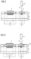
- Fig. 1 is shown as a value document a composite film banknote 1 in plan view.
- Fig. 2 is a cross section through the composite film banknote 1 shown.
- the film composite banknote 1 contains as core a paper layer 2 made of cotton paper, which is coated on both sides with a transparent plastic film 3 made of PET.
- a transparent plastic film 3 made of PET.
- the denomination "50" is shown at the in Fig. 1 right bottom corner of the composite film banknote 1, the denomination "50" is shown.
- the in Fig. 2 illustrated cross section is a cross section of this area. In this area, the paper layer 2 and the plastic film coating 3 above are welded together in a welding region 6 by means of a laser 4 emitting a laser radiation 5.
- the welding area consists of two line-shaped areas, each having a width of about 50 microns to about 500 microns, typically of about 100 microns.
- Fig. 2 represented by the welding in the Verschpar Scheme 6 a firm connection between the upper plastic film 3 and the paper layer 2, and a survey 7 on the surface of the upper plastic film 3 and thus on the surface of the film composite banknote 1.
- the survey 7 forms a tactile Feature that can be sensed or machine detected by a user.
- the laser 4 is an Nd: YAG or an Nd: YVO 4 laser emitting laser radiation 5 with a wavelength of 1064 nm. This laser radiation passes through the plastic film 3 unhindered, but is absorbed by the paper layer 2, so that at the Interface between plastic film 3 and paper layer 2, a welding of the two layers occurs.
- the paper layer 2 contains suitable laser-absorbing substances.
- the upper plastic film 3 further comprises a thermosensitive substance, which shows a color change from transparent to colored above a reversal temperature, so that the transparent prior to welding plastic film 3 in the color change region 8 shows a visually perceptible color.
- the turnover temperature of the thermosensitive substance is below the temperature which occurs when the plastic film 3 is welded to the paper layer 2, so that the color change of the thermosensitive substance in the plastic film 3 does not only occur in the welding region 6, but also in a region 8 around the welding region 6 around.
- this color changeover region 8 has a width of approximately 250 ⁇ m to approximately 500 ⁇ m around the welding region 6.
- the denomination "50" of the composite film banknote 8 can be recognized not only tactilely but also optically.
- Fig. 3 is an alternative structure of the composite film banknote shown in cross section.
- the paper layer 2 is coated next to the plastic film 3 with a further plastic film 9.
- the further plastic film 9 is formed such that the elevation 7 resulting from the welding region 6 is also present on the surface of the further film layer 9.
- the further film layer 9 is formed, for example, sufficiently thin and / or formed from a sufficiently flexible material.
- the further plastic film 9 is sufficiently translucent, for example completely transparent, so that the color change region 8 is visible through the further plastic film layer 9 when the film composite banknote is viewed.
- the further plastic film layer 9 can be before or after the laser welding on the plastic film layer 3 are arranged.
- the welding area may include only the interface between the plastic film 3 and the paper layer 2.
- the welding region can also be chosen such that the welding region completely covers the plastic film 3 and optionally additionally comprises the plastic film 9 partially or completely.
- a welding of several plastic films with the paper substrate 2 can be realized. If the welding area 9 extends as far as the surface of the composite film banknote, then not only is an elevation 7 in the welding area 6, but also an altered surface structure which supports the haptic perceptibility of the elevation 7.
- Fig. 4 is another alternative structure of the film composite banknote 1 shown in cross section.
- the paper layer 2 comprises a coating 10, which forms an intermediate layer between the paper layer 2 and the plastic film 3.
- the coating 10 is in the illustrated embodiment, a paint, to which a laser-absorbing substance is added. Accordingly, the laser radiation incident on laser welding 5 is absorbed in the intermediate layer 10, which leads to a selective welding of the paper layer 2 with the plastic film layer 3 at its interface.
- a region 11 is shown with multiple welds 12.
- the upper plastic film 3 is welded to the paper layer 2 and the welding region 6 as in the right side in Fig. 2 shown.
- a thermosensitive substance is not available in this area.
- the Versch poros 12 of the area 11 form a braille, which indicates the denomination of the composite film banknote 1. This welding region thus forms a denomination-specific identification feature of the film composite banknote 1.
- Fig. 1 is shown in the left area of the film composite banknote 1, a security thread 13 which occurs in areas 14 on the surface of the paper layer 2 and can be perceived by the transparent PET plastic film 3.
- Fig. 5 a cross-section of the composite film banknote along the security thread 13 is shown.
- the security thread 13 is a film strip which is incorporated into the paper layer 2 of the plastic film 1 and, as shown, enters the surface of the paper layer 2 in regions 14. Outside the regions 14, the security thread 13 runs in the interior of the paper layer 2. In the exemplary embodiment shown, this is therefore a window security thread.
- the security thread may also be formed as a pendulum security thread, in which the security thread 13 runs alternately on the upper and lower surface of the paper layer 2.
- the paper layer 2 is coated with a plastic film 3.
- the security thread 13 and the plastic film 3 are arranged directly on each other.
- the plastic film 3 and the security thread 13 can be welded together.
- the welding region 6, in which the security thread 13 and the plastic film 3 are welded together can completely comprise a region 14, as shown on the right in FIG Fig. 5 is shown.
- the welding region 6 may also comprise only a portion of a region 14 in which the security thread 13 comes to the surface of the paper layer 2, as shown on the left in FIG Fig. 5 is shown.
- the plastic film 3 may in turn comprise a substance which shows a color change as a result of the welding. If the welding region 6 is identical to the region 14 in which the security thread 13 comes to the surface of the paper layer 2, the region of the color change 8 is not only formed in register with the welding region 6, but also with the region 14. This register-containing arrangement between the areas 14 in which the security thread 13 comes to the surface of the paper layer 3 and thus visible for example in incident light, and the color change area 8 can be easily checked by a user, but are difficult to imitate by a counterfeiter.
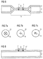
- a continuous recess 15 in the form of a hole can furthermore be provided, as shown in FIG Fig. 1 is shown in plan view.
- This area of the film composite banknote 1 is in Fig. 6 shown in cross section.
- the hole 15 can be as in Fig.1 be circular or have any other shape, for example, be triangular, square, rectangular, square, hexagonal, octagonal or elliptical.
- the plastic films 3, with which the paper layer 2 is coated on both sides, extend beyond the hole 15. In this area, the plastic films 3 are due to the lack of paper layer 2 directly to each other and close the hole 15.
- the welding region 6 In a region 16 of the hole 15 point or line welds or seams 12 are provided and the resulting Verschtab Stud 6 forms a portion of the hole 15th In an embodiment not shown, the welding region 6 completely encloses the hole. As in Fig. 1 already indicated, the welding region 6 within the hole 15 consists of several point or line-shaped Areas, such as welds or welds 12, which represent information 16 for the user of the composite film banknote 1.
- the information 16 may be, for example, a characteristic arrangement of welding spots, as in FIG Fig. 1 represented, or any other characteristic character, letters, numbers, numbers, a picture, a Braille or any other pattern with a recognition value. Examples of such information are in the FIGS. 7a to 7c shown.
- film composite banknote 1 carries in a lower region a film strip 17, which is formed as a patch.
- This area of the film composite banknote 1 is in Fig. 8 shown in cross section.
- the patch 17 is arranged directly on the plastic film 3.
- the patch is welded to the plastic film 3 of the composite film banknote 1, as indicated by the welding regions 6 in FIG Fig. 8 is shown.
- an improved adhesion of patch 17 to the composite film banknote 1 is ensured, which goes beyond the adhesion that is possible by gluing or laminating due to the welding of patch 17 and plastic film 3.
- a non-destructive detachment of patch 17 from the plastic film 3 is prevented by the welding of patch 17 and plastic film 3.
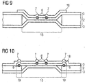
- This in Fig.1 illustrated hole 15 may, as shown, additionally be covered by a further film element 18 in the form of another patch.
- This area of the film composite banknote 1 is in Fig. 9 shown in cross section.
- Patch 18 is arranged directly on the plastic film 3 and overlaps the hole 15 of the paper layer 2. In the region of the hole 15, the patch 18 is welded to the plastic film 3 in a welding region 6. Thereby the plastic film 3 is mechanically stabilized in the region of the hole 15.
- the Verschpar Schl 6 can form an information 16, as in the FIGS. 7a to 7c is shown.
- Fig. 10 an alternative embodiment of the film composite banknote 1 is shown.
- the paper substrate 2 in turn has a continuous recess 15 in the form of a hole.
- This hole 15 is completely covered by the film strip 18 in the form of a patch.
- the patch 18 is arranged in edge regions 19 around the hole 15 directly on the paper layer 2.
- the patch 18 is welded to the paper layer 2.
- the welding region 6 consists of several welding spots.
- the paper layer 2 and the patch 18 are coated by plastic films 3.
- the patch 18 may have the same outline shape as the continuous recess 15.
- the outline of patch 18 can also be selected independently of the outline of the continuous recess 15, as shown for example in FIG Fig. 1 is shown, in which the through recess 15 is circular and patch 18 is square. Further embodiments are in the FIGS. 11a to 11e shown.
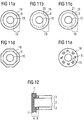
- the continuous recess 15 is formed in the paper layer 2 each circular.
- the patch 18 is also circular and arranged concentrically to the hole 15 on the film composite banknote 1.
- a welding region 6 is provided, in which the patch 18 is welded to the paper layer 2.
- the welding region 6 is a continuous, circular line concentric with the contours of hole 15 and patch 18.
- the welding region 6 is formed by circular arc segments 20 which are located on a circular line which runs concentrically with the contours of hole 15 and patch 18.
- the welding region 6 is formed by welding points 21 which are located on a circular line which runs concentrically to the contours of hole 15 and patch 18.
- the patch 18 is an octagonal element.
- the welding region 6 forms a continuous line, which has a constant distance from the outline of the patch 18 and thus also has an octagonal shape. In general, it is advantageous if the welding region 6 runs in the vicinity of the outline of the patch 18, since in this outer edge region of patch 18 the requirements for the gap strength between patch 18 and the paper substrate 2 are the highest.
- the welding region 6 is formed in the edge region 19 in the form of letters and numbers.
- the Versch favorite Scheme 6 forms an information for a viewer, which can be perceived haptically and / or visually.
- the welding region 6 coincides with the edge of patch 18.
- Fig. 10 illustrated coverage of a hole 15 by means of a patch 18 solves problems that provides the presence of a hole 15 in the paper substrate 2 in the creation of a film composite banknote, that is, when applying a plastic film 3 on both sides.
- the application of a laminating adhesive for the plastic films 3 on both sides to the paper layer 2 (duplex lamination) in the laminating device and in the subsequent winding device leads to the pressing through of the laminating adhesive in the region of the hole 15 and for correspondingly depositing the laminating adhesive on the respective opposite side.
- the patch 18 usually has only a slight adhesion to the plastic film 3, since here, if appropriate, a laminating adhesive and a thermoplastic hot-melt adhesive come to rest on each other. By providing additional welding regions 6 'within hole 15 between patch 18 and plastic film 3, the adhesion of these two layers is increased.
- a weld 22 along the edge of the composite film banknote 1 is shown.
- Fig. 12 is this edge region, that is, the section through the weld 22, shown.
- the film composite banknote 1 comprises a paper layer 2 and plastic film layers 3 on both sides.
- the two-sided film layers 3 are welded together by the weld seam 22 in the edge region of the film composite banknote 1.
- the weld seam 22 forms a further welding region 6.
- Such a weld can be made when separating out the film composite banknote 1 from a multiple-use sheet with a multiplicity of composite film banknotes or by subsequent processing of the edge of the film composite banknote 1 Fig.
- a substance is provided in the plastic film layers 3, which shows a color change due to the welding of the plastic films 3. This occurs in a color change area 8 having a predetermined width.
- the color change area 8 is also in register with the Verschpar Scheme 6, the survey 7 and the edge of the film association banknote 1, which creates another easily verifiable and difficult to imitate security feature.
Landscapes
- Engineering & Computer Science (AREA)
- Mechanical Engineering (AREA)
- Physics & Mathematics (AREA)
- Optics & Photonics (AREA)
- Health & Medical Sciences (AREA)
- Electromagnetism (AREA)
- Toxicology (AREA)
- Thermal Sciences (AREA)
- Manufacturing & Machinery (AREA)
- Chemical & Material Sciences (AREA)
- General Health & Medical Sciences (AREA)
- Business, Economics & Management (AREA)
- Accounting & Taxation (AREA)
- Finance (AREA)
- Composite Materials (AREA)
- Credit Cards Or The Like (AREA)
- Paper (AREA)
Description
Die Erfindung betrifft eine mehrschichtige Anordnung zur Herstellung eines Wertdokuments mit verschweißten Schichten, ein Verfahren zur Herstellung einer solchen mehrschichtigen Anordnung sowie ein Wertdokument.The invention relates to a multilayer arrangement for producing a value document with welded layers, to a method for producing such a multilayer arrangement and to a document of value.
Wertdokumente im Sinne der vorliegenden Erfindung sind beispielsweise Banknoten, Aktien, Anleihen, Urkunden, Gutscheine, Schecks, Lotteriescheine, hochwertige Eintrittskarten, Pässe, Ausweise, Kreditkarten und andere flächige Wertgegenstände. Solche Wertgegenstände können aber auch Verpackungen für gegebenenfalls hochwertige Produkte sein. Der Begriff Wertdokument umfasst im Sinne der vorliegenden Erfindung auch Vorstufen der genannten Wertdokumente, die beispielsweise nicht umlauffähig sind.Value documents within the meaning of the present invention are, for example, banknotes, stocks, bonds, certificates, vouchers, checks, lottery tickets, high-quality admission tickets, passports, identity cards, credit cards and other flat valuables. Such valuables can also be packaging for possibly high-quality products. For the purposes of the present invention, the term value document also includes precursors of the named value documents which, for example, are not fit for circulation.
Solche Wertdokumente, wie Banknoten, umfassen häufig ein schichtartiges Papiersubstrat, welches aus einem faserartigen Material, wie Baumwollfasern, besteht. Ein solches Papiersubstrat kann Sicherheitselemente enthalten, beispielsweise ein Wasserzeichen oder ein Folienelement in Form eines Sicherheitsfadens, der zumindest teilweise in das Papiersubstrat eingearbeitet ist, oder in Form eines Transferelements, wie einem Patch oder einem Etikett, welches auf der Oberfläche des Papiersubstrats angeordnet ist. Das Papiersubstrat ist porös und besitzt eine große Oberfläche und eine hohe Oberflächenrauigkeit. Daher sind solche Papiersubstrate anfällig für Verschmutzungen, welche beispielsweise die Umlaufzeit einer solchen Banknote herabsetzen.Such value documents, such as banknotes, often comprise a sheet-like paper substrate which consists of a fibrous material, such as cotton fibers. Such a paper substrate may contain security elements, for example a watermark or a film element in the form of a security thread, which is at least partially incorporated in the paper substrate, or in the form of a transfer element, such as a patch or a label, which is arranged on the surface of the paper substrate. The paper substrate is porous and has a large surface area and a high surface roughness. Therefore, such paper substrates are susceptible to soils which, for example, reduce the circulation time of such a banknote.
In der
Als Alternative wurden beispielsweise in der
Solche Mehrschichtsubstrate können durch Laminieren der verschiedenen Schichten oder auch durch direkte Extrusion der Kunststofffolie auf eine Papierschicht geschaffen werden. Die verschiedenen Schichten eines solchen Mehrschichtsubstrats sind daher zwar fest verbunden, jedoch ist ein solches Mehrschichtsubstrat nur bedingt spaltfest. Mit anderen Worten können sich die verschiedenen Schichten bereits bei bestimmungsgemäßem Verbrauch voneinander lösen oder vor allem bei einem gezielten Spaltungsangriff voneinander getrennt werden. Solche Mehrschichtsubstrate weisen beispielsweise im Fall von Folienverbundbanknoten gegebenenfalls eine verringerte Umlaufzeit auf. Sie sind zudem infolge ihrer Spaltbarkeit zusätzlichen Fälschungsangriffen ausgesetzt, da beispielsweise Teile des Mehrschichtsubstrats abgespalten werden können und durch Fälschungen ersetzt werden können. Diese Nachteile ergeben sich nicht nur bei Folienverbundbanknoten, sondern generell bei Mehrschichtsubstraten, in denen verschiedene Schichten insbesondere aus verschiedenen Materialien aufeinander angeordnet sind, beispielsweise beim Anordnen eines Transferelementes auf einem Substrat.Such multi-layer substrates can be created by laminating the various layers or by directly extruding the plastic film onto a paper layer. The various layers of such a multilayer substrate are therefore firmly connected, but such a multilayer substrate is only partially gap-resistant. In other words, the different layers can already be separated from one another when they are used as intended, or, above all, they can be separated from one another during a targeted splitting attack. Such multi-layer substrates may have a reduced cycle time, for example in the case of composite film banknotes. They are also exposed due to their cleavage additional counterfeiting attacks, for example, parts of the multilayer substrate can be split off and can be replaced by counterfeiting. These disadvantages do not only arise in laminated film banknotes, but generally in multilayer substrates in which different layers are arranged in particular of different materials to each other, for example when arranging a transfer element on a substrate.
Aufgabe der vorliegenden Erfindung ist es daher, eine mehrschichtige Anordnung zur Herstellung eines Wertdokuments anzugeben, die eine erhöhte Spaltfestigkeit und eine erhöhte Sicherheit gegenüber Spaltungsangriffen bietet und zusätzliche Möglichkeiten zum Einbringen von Merkmalen bietet, die das Wertdokument charakterisieren können. Es ist weiterhin Aufgabe der vorliegenden Erfindung, ein Verfahren zur Herstellung einer solchen mehrschichtigen Anordnung und ein entsprechendes Wertdokument anzugeben.It is therefore an object of the present invention to specify a multilayer arrangement for producing a value document which offers increased gap strength and increased security against splitting attacks and offers additional possibilities for introducing features which can characterize the document of value. It is a further object of the present invention to specify a method for producing such a multilayer arrangement and a corresponding value document.
Diese Aufgabe wird durch ein mehrschichtiges Substrat, ein Wertdokument sowie ein Herstellungsverfahren mit den Merkmalen der unabhängigen Ansprüche gelöst. Die abhängigen Ansprüche betreffen bevorzugte Ausgestaltungen und Weiterbildungen der Erfindung.This object is achieved by a multilayer substrate, a value document and a production method having the features of the independent claims. The dependent claims relate to preferred embodiments and further developments of the invention.
Die erfindungsgemäße mehrschichtige Anordnung für ein Wertdokument umfasst unter anderem eine erste Schicht, die aus einer Kunststofffolie besteht, und eine zweite Schicht, die aus einer weiteren Kunststofffolie besteht, wobei die Schichten zumindest in einem Überlappungsbereich übereinander angeordnet sind und ein Teilbereich des Überlappungsbereichs einen Verschweißbereich bildet, in welchem die erste und die zweite Schicht derart miteinander verschweißt sind, dass der Verschweißbereich ein taktil und/ oder optisch wahrnehmbares Erkennungs- oder Sicherheitsmerkmal des Wertdokumentes bildet. Die erfindungsgemäße mehrschichtige Anordnung für ein Wertdokument kann das Wertdokument selbst, ein Teil des Wertdokuments oder eine Vorstufe des Wertdokuments sein.The multi-layered arrangement according to the invention for a document of value comprises inter alia a first layer which consists of a plastic film and a second layer which consists of a further plastic film, wherein the layers are arranged one above the other at least in an overlapping area and a partial area of the overlapping area forms a welding area in which the first and the second layer are welded together in such a way that the welding region forms a tactile and / or visually perceptible recognition or security feature of the value document. The multilayer arrangement according to the invention for a value document can be the value document itself, a part of the value document or a preliminary stage of the value document.
Bei der Kunststofffolie kann es sich um PET (Polyethylenterephthalat), OPP (Orientiertes Polypropylen), PE (Polyethylen), PC (Polycarbonat), PA (Polyamid) oder ein Gemisch aus diesen Materialien handeln. Es sind jedoch auch alle anderen geeigneten Kunststoffmaterialien und deren Gemische einsetzbar. Die Kunststofffolie ist vorzugsweise thermoplastisch. Je nach Anwendung kann die Kunststofffolie bereichsweise mattiert oder glänzend ausgeführt werden. Eine solche bereichsweise Mattierung kann durch Abdecken der Folien mit einem Resistlack und anschließendes Ätzen der Folienoberfläche in dem nicht durch den Resistlack abgedeckten Bereich erhalten werden.The plastic film can be PET (polyethylene terephthalate), OPP (oriented polypropylene), PE (polyethylene), PC (polycarbonate), PA (polyamide) or a mixture of these materials. However, all other suitable plastic materials and mixtures thereof can be used. The plastic film is preferably thermoplastic. Depending on the application, the plastic film may be partially matted or glossy. Such a partial matting can be obtained by covering the films with a resist and then etching the film surface in the area not covered by the resist.
Die Kunststofffolie kann zusätzlich monoaxial oder biaxial gereckt sein. Eine solche Reckung der Kunststofffolie führt unter anderem zu einer erhöhten Einreißfestigkeit der mehrschichtigen Anordnung.The plastic film may additionally be monoaxially or biaxially stretched. Such a stretching of the plastic film leads inter alia to an increased tear strength of the multilayer arrangement.
Als Papier kommt jede Art von Papier oder papierartigem Material in Betracht, insbesondere Baumwollpapier. Es kann auch Papier eingesetzt werden, dessen Fasern einen gewissen Anteil x eines Polymermaterials im Bereich zwischen 0 und 100 Gew.-% enthalten.The paper may be any kind of paper or papery material, in particular cotton paper. It is also possible to use paper whose fibers contain a certain proportion x of a polymer material in the range between 0 and 100% by weight.
Erfindungsgemäß werden die erste und die zweite Schicht im Überlappungsbereich übereinander angeordnet. Vorzugsweise sind die erste und zweite Schicht vollständig überlappend ausgebildet.According to the invention, the first and the second layer are arranged one above the other in the overlapping area. Preferably, the first and second layers are formed completely overlapping.
Durch das anschließende Verschweißen wird eine feste Verbindung zwischen der ersten und der zweiten Schicht geschaffen, die gegebenenfalls eine weitere Verbindung der beiden Schichten darstellt. Beim Verschweißen schmilzt die Kunststofffolie der ersten Schicht teilweise auf und dringt in das Papier ein. Besteht das Papier aus Kunststofffasern, so können diese ebenfalls aufschmelzen und mit der Kunststofffolie der ersten Schicht eine feste Verbindung eingehen. Besteht die zweite Schicht aus einer weiteren Kunststofffolie, so kann diese je nach Wahl der Materialien ebenfalls aufschmelzen und somit wiederum mit der Kunststofffolie der ersten Schicht eine feste Verbindung eingehen. Durch das Verschweißen der ersten und der zweiten Schicht wird die Haftung der beiden Schichten aufeinander erhöht und somit die Verbundstabilität der erfindungsgemäßen mehrschichtigen Anordnung erhöht. Dadurch wird die Spaltfestigkeit der mehrschichtigen Anordnung erhöht. Da beim Verschweißen zumindest die Kunststofffolie der ersten Schicht schmilzt und sich mit der zweiten Schicht verbindet, liegt die erste Schicht nach dem Verschweißen in dem Verschweißbereich in veränderter Form vor. Folglich ist kein zerstörungsfreies Ablösen der ersten Schicht von der zweiten Schicht mehr möglich.By the subsequent welding a firm connection between the first and the second layer is created, which optionally a represents further connection of the two layers. During welding, the plastic film of the first layer partially melts and penetrates into the paper. If the paper consists of synthetic fibers, they can also melt and form a firm bond with the plastic film of the first layer. If the second layer consists of a further plastic film, this can also melt depending on the choice of materials and thus in turn enter into a firm connection with the plastic film of the first layer. By welding the first and the second layer, the adhesion of the two layers to one another is increased and thus the composite stability of the multilayer arrangement according to the invention is increased. As a result, the gap strength of the multilayer arrangement is increased. Since during welding at least the plastic film of the first layer melts and bonds to the second layer, the first layer is present after the welding in the welding area in a modified form. Consequently, non-destructive peeling of the first layer from the second layer is no longer possible.
Erfindungsgemäß bildet der Verschweißbereich ein taktil und/oder optisch wahrnehmbares Erkennungs- oder Sicherheitsmerkmal. Dies wird durch eine geeignete Wahl der Verschweißtechnik und durch eine geeignete Abstimmung der Schweißparameter auf die zu verschweißenden ersten und zweiten Schichten erreicht.According to the invention, the welding region forms a tactile and / or visually perceptible recognition or security feature. This is achieved by a suitable choice of the welding technique and by a suitable coordination of the welding parameters on the first and second layers to be welded.
In einer bevorzugten Ausgestaltung findet das Verschweißen mit einer Schweißtechnik wie Laserschweißen oder Ultraschallschweißen, beispielsweise rotativem Ultraschallschweißen, statt. Mit diesen Techniken ist es möglich, einen flächigen Bereich zu verschweißen. Bei dem Laserschweißen handelt es sich um eine berührungsfreie Schweißtechnik. Das Ultraschallschweißen ist im Gegensatz zum Laserschweißen nicht berührungsfrei, sondern es werden gravierte Walzen in das Material gedrückt.In a preferred embodiment, the welding takes place with a welding technique such as laser welding or ultrasonic welding, for example rotary ultrasonic welding. With these techniques, it is possible to weld a flat area. Laser welding is a non-contact welding technique. The ultrasonic welding In contrast to laser welding, it is not contact-free, but engraved rollers are pressed into the material.
Bevorzugt werden die Parameter beim Schweißprozess derart gewählt, dass zu einem gegebenen Zeitpunkt ein Verschweißen nur in einem punktuellen Bereich stattfindet, der das Erzeugen von Schweißpunkten oder Schweißlinien bzw. Schweißnähten mit einem Durchmesser von weniger als 10 µm, 20 µm, 30 µm, 50 µm oder 100 µm gestattet. Je nach Material der beiden zu verschweißenden Schichten und der Parameter der Schweißprozesse kann somit ein beispielsweise punkt- oder linienförmiger Verschweißbereich geschaffen werden, der einen gegenüber nicht verschweißten Bereichen erhabenen Bereich und somit ein taktiles Merkmal für das Wertdokument bildet. Das taktile Merkmal kann durch einen Benutzer haptisch erkannt werden oder maschinell detektiert werden. Bei einem solchen rein taktilen Merkmal ist die Transparenz der ersten und der zweiten Schicht unerheblich, und es können vollständig opake, transluzente, das heißt teilweise transparente, oder vollständig transparente Materialien für die beiden zu verschweißenden Schichten oder gegebenenfalls für weitere darüber oder darunter angeordnete Schichten gewählt werden. Insbesondere beim Ultraschallschweißen, das nicht berührungsfrei erfolgt, können Verschweißbereiche geschaffen werden, die man als Verprägungen bzw. Prägestrukturen oder sogar als Perforationen bezeichnen kann.In the welding process, the parameters are preferably selected such that at a given point in time welding only takes place in a punctiform area which produces welding spots or weld lines or welds with a diameter of less than 10 μm, 20 μm, 30 μm, 50 μm or 100 microns allowed. Depending on the material of the two layers to be welded and the parameters of the welding processes, it is thus possible, for example, to create a spot or line-shaped welding region which forms a region raised in relation to non-welded regions and thus a tactile feature for the document of value. The tactile feature can be haptically recognized by a user or detected by machine. In such a purely tactile feature, the transparency of the first and second layers is insignificant, and completely opaque, translucent, ie, partially transparent, or completely transparent materials may be selected for the two layers to be welded, or optionally for further layers above or below become. In particular, in ultrasonic welding, which does not occur without contact, Verschweißbereiche can be created, which can be described as stampings or embossed structures or even as perforations.
Alternativ oder zusätzlich können die Parameter des Schweißprozesses und die Materialien der ersten und der zweiten Schicht so aufeinander abgestimmt werden, dass der Verschweißbereich der ersten und zweiten Schicht optisch wahrnehmbar ist. Im einfachsten Fall wird der Verschweißbereich durch das Verschweißen geschwärzt, wobei die Transparenz bzw. die Opazität der ersten und der zweiten Schicht und gegebenenfalls weiterer darüber oder darunter angeordneter Schichten geeignet gewählt sein muss, so dass der optisch veränderte Verschweißbereich wahrnehmbar ist. Das optische Erkennen des Verschweißbereichs kann visuell durch einen Benutzer oder maschinell geschehen.Alternatively or additionally, the parameters of the welding process and the materials of the first and the second layer can be coordinated so that the welding region of the first and second layers is visually perceptible. In the simplest case, the welding region is blackened by the welding, wherein the transparency or the opacity of the first and the second layer and optionally further about or layers arranged therebelow must be suitably chosen so that the optically changed weld region is perceptible. The visual recognition of the weld area can be done visually by a user or by machine.
Wie erwähnt, kann durch die Auswahl von Laserschweißen oder Ultraschallschweißen als Schweißtechnik der Bereich, in dem zu einem gegebenen Zeitpunkt das Verschweißen von erster und zweiter Schicht stattfindet, sehr klein gewählt werden. Entsprechend kann der Verschweißbereich eine Information für den Betrachter bilden, beispielsweise in Form von Zeichen, Zahlen, Buchstaben, Bildern oder sonstigen charakteristischen Mustern, die dabei eine hohe graphische Auflösung aufweisen können. Der Verschweißbereich kann daher bereits aufgrund seiner Ausgestaltung ein Sicherheitsmerkmal des Wertdokumentes bilden. Alternativ ist es beispielsweise auch denkbar, einen taktil erkennbaren Verschweißbereich in Form von charakteristischen Erhebungen, beispielsweise einer Währungs- und/oder denominationsspezifischen Blindenschrift, vorzusehen.As mentioned, by selecting laser welding or ultrasonic welding as the welding technique, the range in which welding of the first and second layers takes place at a given time can be made very small. Accordingly, the Verschweißbereich form information for the viewer, for example in the form of characters, numbers, letters, images or other characteristic patterns, which may have a high graphic resolution. The welding area can therefore already form a security feature of the value document due to its design. Alternatively, it is also conceivable, for example, to provide a tactile weldable region in the form of characteristic elevations, for example a currency and / or denomination-specific Braille.
Die Laserstrahlung oder der Ultraschall, die bzw. der zum Verschweißen verwendet wird, trifft beispielsweise senkrecht oder auch unter einem Winkel gegenüber der Oberflächennormalen der ersten und der zweiten Schicht auf die mehrschichtige Anordnung auf. Die Verwendung einer Schweißtechnik wie das Laser- oder Ultraschallschweißen gestattet es, nur die erste und die zweite Schicht mit der Zwischenschicht aus Papier miteinander zu verschweißen, auch wenn in Strahlungsrichtung bzw. in Richtung der Beschallung vor oder hinter der ersten und der zweiten Schicht weitere Schichten angeordnet sind. Mit anderen Worten gestatten diese Schweißtechniken das gezielte Verschweißen innen liegender Schichten. Dies kann z.B. dadurch geschehen, dass die Laserstrahlung fokussiert wird und die Intensität der zum Verschweißen verwendeten Strahlung derart auf die erste und zweite Schicht abgestimmt ist, dass ein Verschweißen der ersten und der zweiten Schicht nur bei verringertem Strahlquerschnitt, insbesondere im Fokus der Laserstrahlung, stattfindet. Alternativ oder zusätzlich können in der ersten und/oder zweiten Schicht laserstrahlungssensitive oder ultraschallsensitive Substanzen eingebracht sein, die die Laserstrahlung bzw. den Ultraschall absorbieren. Dadurch wird die eingestrahlte Laserstrahlung bzw. der Ultraschall gezielt in der entsprechenden Schicht absorbiert, wodurch sich diese Schicht lokal erhitzt, aufschmilzt und entsprechend mit der benachbarten Schicht verschweißt.The laser radiation or ultrasound used for welding, for example, is perpendicular to or at an angle to the surface normal of the first and the second layer on the multilayer arrangement. The use of a welding technique such as laser or ultrasonic welding makes it possible to weld together only the first and the second layer with the intermediate layer of paper, even if further layers in the radiation direction or in the direction of the sound before or after the first and the second layer are arranged. In other words, these welding techniques allow the selective welding of internal layers. This can be done, for example, by the fact that the laser radiation is focused and the intensity of the radiation used for welding is matched to the first and second layer, that a welding of the first and the second layer takes place only with reduced beam cross-section, in particular in the focus of the laser radiation. Alternatively or additionally, laser-radiation-sensitive or ultrasound-sensitive substances which absorb the laser radiation or the ultrasound can be introduced into the first and / or second layer. As a result, the irradiated laser radiation or the ultrasound is absorbed in a targeted manner in the corresponding layer, as a result of which this layer locally heats up, melts and then welds to the adjacent layer.
Zum Laserschweißen können Nd:YAG- oder Nd:YVO4-Laser einsetzt werden. Diese emittieren eine Laserstrahlung mit einer Wellenlänge von 1064 nm die von Materialien, wie PET, nicht oder nur geringfügig absorbiert wird. In die zu verschweißenden Schichten oder in eine der beiden zu verschweißenden Schichten können dann diese Laserstrahlung absorbierende Substanzen eingebracht werden, wie Bis(4-dimethylaminodithiobenzil)nickel oder N,N,N',N'-Tetrakis[4-bis(3-cyanopropyl)aminophenyl]-p-phenylenediaminiumdihexafluorophosphate.For laser welding Nd: YAG or Nd: YVO 4 laser can be used. These emit laser radiation with a wavelength of 1064 nm which is not or only slightly absorbed by materials such as PET. In the layers to be welded or in one of the two layers to be welded then these laser radiation absorbing substances can be introduced, such as bis (4-dimethylaminodithiobenzil) nickel or N, N, N ', N'-tetrakis [4-bis (3-cyanopropyl ) aminophenyl] -p-phenylenediaminiumdihexafluorophosphate.
Beim Ultraschallschweißen können entsprechend ultraschallabsorbierend wirkende Substanzen, wie beispielsweise Klebstoffe mit Isocyanat- oder Acrylat-Systemen, verwendet werden. Diese sind vorzugsweise zusätzlich als wärmeaktivierbare Klebstoffe ausgebildet.In ultrasonic welding, correspondingly ultrasound-absorbing substances, such as, for example, adhesives with isocyanate or acrylate systems, can be used. These are preferably additionally designed as heat-activatable adhesives.
Die erste und die zweite Schicht werden verschweißt, obwohl sie nicht direkt aufeinander angeordnet sind, sondern durch eine oder gegebenenfalls mehrere Zwischenschichten getrennt sind. Die Zwischenschicht ist dabei derart ausgestaltet, dass sie das Verschweißen von erster und zweiter Schicht nicht behindert. Dies kann dadurch geschehen, dass die Zwischenschicht beim Verschweißen der ersten und der zweiten Schicht im Verschweißbereich verdrängt wird oder die Schmelze der ersten und gegebenenfalls der zweiten Schicht die Zwischenschicht vollständig durchdringt und somit eine direkte Verbindung der ersten und der zweiten Schicht durch Verschweißen schafft.The first and second layers are welded, although they are not arranged directly on top of one another, but are separated by one or possibly several intermediate layers. The intermediate layer is designed such that it is the first welding and second layer not obstructed. This can be done by displacing the intermediate layer during welding of the first and the second layer in the welding region, or by allowing the melt of the first and optionally the second layer to completely penetrate the intermediate layer and thus create a direct connection of the first and second layers by welding.
Erfindungsgemäß handelt es sich bei der ersten und der zweiten Schicht jeweils um eine Kunststofffolie, die nicht direkt aufeinander angeordnet sind, sondern durch eine oder gegebenenfalls mehrere Zwischenschichten aus Papier getrennt sind. Durch Ultraschall werden die beiden Kunststofffolien durch das Papier hindurch miteinander verschweißt bzw. verprägt. Die aus Papier gebildete Zwischenschicht wird beim Verschweißen der ersten und der zweiten Schicht im Verschweißbereich verdrängt. Dadurch ergibt sich eine besonders gute Spaltfestigkeit des Kunststofffolie/Papier/Kunststofffolie-Verbundes. In Abhängigkeit von den Bedingungen, unter denen das Ultraschallschweißen durchgeführt wird, stellen die Verschweißbereiche Verprägungen bzw. Prägestrukturen oder sogar Perforationen dar. Die Prägestrukturen oder Perforationen sind taktil gut wahrnehmbar.According to the invention, the first and the second layer are each a plastic film which are not arranged directly on top of each other but are separated by one or possibly several intermediate layers of paper. By ultrasound, the two plastic films are welded together or embossed through the paper. The intermediate layer formed of paper is displaced in the welding region during welding of the first and the second layer. This results in a particularly good gap strength of the plastic film / paper / plastic film composite. Depending on the conditions under which the ultrasonic welding is carried out, the welding areas represent embossing or embossing structures or even perforations. The embossed structures or perforations are tactilely perceptible.
Die Zwischenschicht kann ebenfalls laser- oder ultraschallsensitiv ausgebildet sein, so dass sie Laserstrahlung bzw. Ultraschall absorbiert. Dadurch wird ebenfalls eine lokale Absorption und entsprechende Erhitzung der Zwischenschicht, und somit der Grenzschicht zwischen erster und zweiter Schicht, gewährleistet.The intermediate layer may also be laser-sensitive or ultrasound-sensitive, so that it absorbs laser radiation or ultrasound. This also ensures a local absorption and corresponding heating of the intermediate layer, and thus the boundary layer between the first and second layer.
Erfindungsgemäß bildet der Verschweißbereich, in dem die erste und die zweite Schicht miteinander verschweißt sind, einen taktil und/oder optisch wahrnehmbaren Bereich. In einer vorteilhaften Ausgestaltung umfasst die erste und/oder zweite Schicht, die Zwischenschicht oder gegebenenfalls eine benachbarte Schicht eine Laser-sensitive und/oder Ultraschall-sensitive und/oder thermosensitive Substanz, die infolge der einfallenden Laserstrahlung oder infolge des Ultraschalls oder infolge der beim Verschweißen auftretenden Erwärmung einen Farbumschlag zeigt. Dieser Farbumschlag kann von transparent zu farbig sein, von farbig zu transparent oder von einer ersten Farbe zu einer zweiten Farbe. Der Bereich, in dem der Farbumschlag stattfindet, ist dabei vorzugsweise größer, das heißt breiter, als der Bereich, in dem zu einem gegebenen Zeitpunkt das Verschweißen der ersten und der zweiten Schicht stattfindet. Dies kann dadurch erreicht werden, dass der Farbumschlag bereits bei einer geringeren Intensität der einfallenden Laserstrahlung oder des einfallenden Ultraschalls verglichen mit der Intensität beim Verschweißen oder bei einer geringeren Temperatur als die beim Verschweißen auftretende Temperatur, stattfindet. Da unabhängig davon, ob der Farbumschlag auf eine Laser-sensitive, Ultraschall-sensitive oder thermosensitive Eigenschaft der Substanz zurückgeht, der Farbumschlag beim Arbeitsschritt des Verschweißens stattfindet, weist der Bereich des Farbumschlags eine vorgegebene, konstante Breite um den Verschweißbereich auf. Mit anderen Worten ist der Bereich des Farbumschlags perfekt registerhaltig zu dem Verschweißbereich angeordnet. Eine solche registerhaltige Anordnung des Bereichs des Farbumschlags und des Verschweißbereichs bildet ein Sicherheitsmerkmal, das zum einen von einem Betrachter aufwandsarm überprüft werden kann und zum anderen nur schwer nachgeahmt werden kann. Entsprechend weist dies Sicherheitsmerkmal eine hohe Fälschungssicherheit auf.According to the invention, the welding region, in which the first and the second layer are welded together, forms a tactile and / or optically perceivable region. In an advantageous embodiment, the first and / or second layer, the intermediate layer or optionally an adjacent layer comprises a laser-sensitive and / or ultrasound-sensitive and / or thermosensitive substance, due to the incident laser radiation or as a result of ultrasound or as a result of welding occurring heating shows a color change. This color change can be from transparent to colored, from colored to transparent or from a first color to a second color. The region in which the color change takes place is preferably larger, that is wider, than the region in which the welding of the first and the second layer takes place at a given time. This can be achieved in that the color change takes place even at a lower intensity of the incident laser radiation or the incident ultrasound compared with the intensity during welding or at a lower temperature than the temperature occurring during welding. Regardless of whether the color change is due to a laser-sensitive, ultrasound-sensitive or thermosensitive property of the substance, the color change takes place during the welding operation, the area of the color change has a predetermined, constant width around the welding region. In other words, the area of the color change is arranged perfectly in register with the welding area. Such a register-containing arrangement of the region of the color change and the Verschweißbereichs forms a security feature that can be checked with little effort by a viewer and on the other hand can be hard to imitate. Accordingly, this security feature has a high security against counterfeiting.
Im Sinne der vorliegenden Schrift werden als thermo-, laser- oder ultraschallsensitiv Substanzen bezeichnet, die die oder den beim Schweißen verwendete Laserstrahlung bzw. Ultraschall absorbieren und/oder infolge der einfallenden Laserstrahlung oder des einfallenden Ultraschalls oder infolge der beim Verschweißen auftretenden erhöhten Temperatur einen Farbumschlag zeigen.For the purposes of the present specification, substances which absorb the laser radiation or ultrasound used in welding and / or ultrasound and / or as a result of incident laser radiation or incident ultrasound or as a result of the elevated temperature occurring during welding are referred to as thermal, laser or ultrasound-sensitive substances demonstrate.
In einer bevorzugten Ausgestaltung weist das Wertdokument, das die erfindungsgemäße mehrschichtige Anordnung aufweist, einen Umriss mit Ecken und Kanten auf. Beispielsweise weist das Wertdokument einen rechteckigen Umriss auf, wie dies typischerweise bei Banknoten der Fall ist. In einer vorteilhaften Ausgestaltung ist der Verschweißbereich als ein Schweißpunkt an einer Ecke oder als jeweils ein Schweißpunkt an mehreren, vorzugsweise allen Ecken des Wertdokumentes ausgebildet. Dies gestattet ein sicheres taktiles und/oder optisches Wahrnehmen der Ecke oder gegebenenfalls der Ecken des Wertdokuments. Alternativ können auch mehrere Schweißpunkte an der Kante des Wertdokumentes im Bereich der Ecken vorgesehen sein. Weiter alternativ kann der Verschweißbereich als linienförmiger Bereich entlang einer oder mehrerer Kanten des Wertdokumentes ausgebildet sein. Beispielsweise kann ein linienförmiger Schweißbereich an den Kanten des Wertdokumentes im Bereich der Ecken oder abschnittsweise an einer oder mehreren Kanten in von den Ecken beabstandeten Bereichen vorgesehen sein. Besonders bevorzugt ist der Verschweißbereich auf dem Wertdokument umlaufend ausgebildet und umfasst alle Ecken und Kanten des Wertdokumentes. Ein solches Vorsehen des Verschweißbereichs an den Ecken und/ oder Kanten des Wertdokumentes erhöht die Spaltfestigkeit des Wertdokumentes. Ist in der mehrschichtigen Anordnung des Wertdokumentes zusätzlich eine Substanz vorgesehen, die den oben beschriebenen Farbumschlag zeigt, so werden dadurch nicht nur die erwähnten Vorteile erzielt, sondern auch die Wahrnehmbarkeit des Umrisses des Wertdokumentes zusätzlich unterstützt. In allen Ausgestaltungen können die z.B. durch Laserstrahlung oder Ultraschall erzeugten Verschweißbereiche darüber hinaus für ein attraktives Design genutzt werden, gegebenenfalls in Verbindung mit einem Aufdruck oder anderen Sicherheitsmerkmalen.In a preferred embodiment, the value document, which has the multilayer arrangement according to the invention, has an outline with corners and edges. For example, the value document has a rectangular outline, as is typically the case with banknotes. In an advantageous embodiment, the welding region is formed as a welding point at a corner or as a respective welding point at a plurality, preferably all corners of the document of value. This allows a secure tactile and / or visual perception of the corner or possibly the corners of the value document. Alternatively, a plurality of welds may be provided at the edge of the document of value in the region of the corners. As an alternative, the welding region can be formed as a linear region along one or more edges of the document of value. For example, a line-shaped welding area may be provided at the edges of the document of value in the region of the corners or in sections at one or more edges in areas spaced from the corners. Particularly preferably, the welding area is formed circumferentially on the value document and includes all corners and edges of the value document. Such provision of the welding region at the corners and / or edges of the document of value increases the nip strength of the document of value. If, in addition, a substance is provided in the multi-layered arrangement of the document of value, which shows the color change described above, then not only the mentioned advantages are achieved, but also also the perceptibility of the outline of the document of value additionally supported. In all embodiments, the Verschweißbereiche example generated by laser radiation or ultrasound can also be used for an attractive design, optionally in conjunction with a print or other security features.
Häufig werden Wertdokumente, wie Banknoten, in Form von Bogen, so genannten Mehrnutzen-Bogen, hergestellt, in denen mehrere Wertdokumente nebeneinander angeordnet sind. Ein einzelnes Wertdokument wird dann aus einem solchen Bogen herausgetrennt, beispielsweise herausgeschnitten. In einer vorteilhaften Ausgestaltung dieses Verfahrens umfasst der Bogen die erfindungsgemäßen ersten und zweiten Schichten und das Heraustrennen eines Wertdokumentes geschieht durch Laser- oder Ultraschallschweißen derart, dass die erste und die zweite Schicht zugleich an den durch das Heraustrennen entstehenden Kanten des Wertdokumentes miteinander verschweißen. Der entstehende Verschweißbereich bildet somit den Rand, das heißt die Kante des Wertdokumentes. Da das Heraustrennen des Wertdokuments aus einem solchen Bogen im gleichen Arbeitsschritt erfolgt wie das Verschweißen der ersten und zweiten Schicht, liegt der Verschweißbereich perfekt registerhaltig zu der Kante des Umrisses des Wertdokumentes. Diese Registerhaltigkeit von Kante und Verschweißbereich bildet wiederum ein Sicherheitsmerkmal, das leicht überprüft und nur schwer nachgeahmt werden kann. Zusätzlich wird durch das Vorsehen des Verschweißbereichs an der Kante des Umrisses des Wertdokuments, das Wertdokument seitlich verschlossen und die Spaltfestigkeit erhöht.Often value documents, such as banknotes, in the form of sheets, so-called multi-benefit sheet produced, in which several value documents are arranged side by side. A single value document is then separated from such a sheet, for example, cut out. In an advantageous embodiment of this method, the sheet comprises the first and second layers according to the invention and the separation of a document of value is done by laser or ultrasonic welding such that the first and the second layer welded together at the edges resulting from the separation of the value document. The resulting Verschweißbereich thus forms the edge, that is, the edge of the document of value. Since the removal of the value document from such a sheet takes place in the same work step as the welding of the first and second layers, the welding region lies perfectly in register with the edge of the outline of the document of value. This registration of edge and weld area again provides a security feature that is easily verified and difficult to mimic. In addition, by providing the welding area at the edge of the outline of the value document, the value document is laterally closed and the nip strength is increased.
Vorzugsweise umfasst die mehrschichtige Anordnung des Wertdokumentes auch eine Substanz, die einen wie oben beschriebenen Farbumschlag durch das Laser- oder Ultraschallschweißen beim Heraustrennen des Wertdokuments aus dem Bogen zeigt, wodurch die Kante des Wertdokumentes, der Verschweißbereich und der Bereich des Farbumschlages perfekt registerhaltig zueinander angeordnet sind. Dies bildet ein Sicherheitsmerkmal mit weiter erhöhter Fälschungssicherheit.Preferably, the multi-layered arrangement of the document of value also comprises a substance having a color change as described above by the laser or ultrasonic welding when separating out the document of value shows from the sheet, whereby the edge of the document of value, the welding area and the area of the color change are perfectly in register with each other. This forms a security feature with further increased counterfeit security.
Wie bereits beschrieben, gestattet das Laser- oder Ultraschallschweißen ein gezieltes Verschweißen innen liegender Schichten. Dabei sind zumindest in Betrachtungsrichtung, aus der das Wertdokument zu betrachten ist, vor der ersten und zweiten Schicht liegende weitere Schichten derart ausgebildet, dass die Wahrnehmbarkeit des durch den Verschweißbereich und gegebenenfalls den Bereich des Farbumschlags gebildeten Erkennungs- oder Sicherheitsmerkmals nicht oder nur unwesentlich beeinträchtigt wird. Dies kann dadurch erreicht werden, dass die weiteren Schichten ausreichend dünn sind, so dass die taktile Charakteristik des Verschweißbereichs weiterhin erkannt werden kann, oder dass die weiteren Schichten ausreichend transparent sind, so dass die optische Charakteristik des Verschweißbereichs und/oder gegebenenfalls des Farbumschlagbereichs weiterhin erkannt werden kann. Solche weiteren Schichten können zeitlich vor oder nach dem Verschweißen oberhalb oder unterhalb der ersten und zweiten Schichten angeordnet werden.As already described, the laser or ultrasonic welding allows targeted welding of internal layers. At least in the viewing direction, from which the document of value is to be considered, further layers lying in front of the first and second layers are formed in such a way that the perceptibility of the recognition or security feature formed by the welding region and optionally the region of the color change is not or only insignificantly impaired , This can be achieved in that the further layers are sufficiently thin so that the tactile characteristic of the welding region can still be recognized, or that the further layers are sufficiently transparent, so that the optical characteristic of the welding region and / or optionally the color change region is still recognized can be. Such additional layers may be arranged above or below the first and second layers before or after welding.
In einer bevorzugten Ausgestaltung ist das Wertdokument, das die erfindungsgemäße mehrschichtige Anordnung umfasst, eine Folienverbundbanknote, die entweder einen Papierkern mit beidseitiger Kunststofffolienbeschichtung oder einen Kunststofffolienkern mit beidseitiger Papierbeschichtung umfasst. Die erste und/oder zweite Schicht können dabei das Substrat des Wertdokumentes, eine Beschichtung des Substrats oder ein sonstiges auf dem Wertdokument angeordnetes Element, insbesondere ein Folienelement wie ein Folienstreifen, ein Patch oder ein Sicherheitsfaden sein. Dabei ist eine Vielzahl von Varianten möglich, von denen die nachfolgenden Figuren und bevorzugten Ausführungsbeispiele nur Beispiele darstellen.In a preferred embodiment, the document of value comprising the multi-layered assembly according to the invention is a laminated film banknote which comprises either a paper core with double-sided plastic film coating or a plastic film core with double-sided paper coating. The first and / or second layer may be the substrate of the document of value, a coating of the substrate or another element arranged on the document of value, in particular a film element such as a film strip, a patch or a security thread be. In this case, a plurality of variants is possible, of which the following figures and preferred embodiments represent only examples.
Ausführungsbeispiele und Vorteile der Erfindung werden nachfolgend beispielhaft anhand der begleitenden Figuren erläutert. Die Beispiele stellen bevorzugte Ausführungsformen dar, die die Erfindung in keiner Weise beschränken. Die gezeigten Figuren sind schematische Darstellungen, die die realen Proportionen nicht widerspiegeln, sondern einer verbesserten Anschaulichkeit der verschiedenen Ausführungsbeispiele dienen.Exemplary embodiments and advantages of the invention are explained below by way of example with reference to the accompanying figures. The examples represent preferred embodiments which in no way limit the invention. The figures shown are schematic representations that do not reflect the real proportions, but serve an improved clarity of the various embodiments.
Im Einzelnen zeigen die Figuren:
- Fig. 1
- eine Folienverbundbanknote in Draufsicht;
- Fig. 2
- einen ersten Querschnitt durch die Folienverbundbanknote;
- Fig. 3
- einen Querschnitt durch eine weiteres Ausführungsbeispiel der Folienverbundbanknote;
- Figuren 4
bis 6 - verschiedene Querschnitte durch die Folienverbundbanknote;
- Figuren 7a bis 7c
- Draufsichten auf verschiedene Ausführungsbeispiele eines Lochbereichs der Folienverbundbanknote;
Figuren 8bis 10- verschiedene Querschnitte durch die Folienverbundbanknote;
- Figuren 11a bis 11e
- Draufsichten auf verschiedene Ausführungsbeispiele eines abgedeckten Lochbereichs der Folienverbundbanknote; und
- Fig. 12
- einen Querschnitt durch einen Randbereich der Folienverbundbanknote.
- Fig. 1
- a composite film banknote in plan view;
- Fig. 2
- a first cross section through the composite film banknote;
- Fig. 3
- a cross section through a further embodiment of the film composite banknote;
- FIGS. 4 to 6
- different cross sections through the composite film banknote;
- FIGS. 7a to 7c
- Top views of various embodiments of a hole portion of the composite film banknote;
- FIGS. 8 to 10
- different cross sections through the composite film banknote;
- FIGS. 11a to 11e
- Top views of various embodiments of a covered hole portion of the film composite banknote; and
- Fig. 12
- a cross section through an edge region of the film composite banknote.
In
Die obere Kunststofffolie 3 umfasst weiterhin eine thermosensitive Substanz, die oberhalb einer Umschlagstemperatur einen Farbumschlag von transparent zu farbig zeigt, so dass die vor dem Verschweißen transparente Kunststofffolie 3 in dem Farbumschlagsbereich 8 eine optisch wahrnehmbare Farbe zeigt. Die Umschlagstemperatur der thermosensitiven Substanz liegt dabei unterhalb der Temperatur, die beim Verschweißen der Kunststofffolie 3 mit der Papierschicht 2 auftritt, so dass der Farbumschlag der thermosensitiven Substanz in der Kunststofffolie 3 nicht nur im Verschweißbereich 6 auftritt, sondern auch in einem Bereich 8 um den Verschweißbereich 6 herum. Im vorliegenden Ausführungsbeispiel weist dieser Farbumschlagbereich 8 eine Breite von etwa 250 µm bis etwa 500 µm um den Verschweißbereich 6 herum auf. Somit kann die Denomination "50" der Folienverbundbanknote 8 nicht nur taktil, sondern auch optisch erkannt werden.The
In
Wie in
In
In
In der Folienverbundbanknote 1 kann weiterhin eine durchgehende Ausnehmung 15 in Form eines Lochs vorgesehen sein, wie dies in
Die in
Das in
In
In den in den
Die in
Am linken Rand der in
Zusätzlich ist in den Kunststofffolienschichten 3 eine Substanz vorgesehen, die infolge des Verschweißens der Kunststofffolien 3 einen Farbumschlag zeigt. Dieser tritt in einem Farbumschlagbereich 8 auf, der eine vorgegebene Breite aufweist. Somit liegt der Farbumschlagsbereich 8 ebenfalls registerhaltig zu dem Verschweißbereich 6, der Erhebung 7 und dem Rand der Folienverbandbanknote 1, was ein weiteres leicht überprüfbares und schwer nachahmbares Sicherheitsmerkmal schafft.In addition, a substance is provided in the plastic film layers 3, which shows a color change due to the welding of the
Wie in
Claims (14)
- A multilayer arrangement for a value document, comprising a first layer consisting of a plastic foil and a second layer consisting of a further plastic foil, wherein the plastic foils are separated by one or possibly several intermediate layers of paper, characterized in that the plastic foils are arranged above each other at least in an overlap area and at least one partial area of the overlap area forms a welding area in which the first and the second plastic foil are welded to each other in such a fashion that the welding area forms a tactilely and/or optically perceivable recognition or security feature.
- The multilayer arrangement according to claim 1, characterized in that the first and/or the second layer are formed by any one of the following alternatives:- a foil element, in particular a patch, a foil strip or a security thread,- a substrate of the value document, in particular a substrate with a continuous gap,- a coating of the substrate of the value document, in particular in the form of a foil element.
- The multilayer arrangement according to any of the preceding claims, characterized in that the first and second layer are welded to each other by applying a welding method, preferably by laser or ultrasonic welding.
- The multilayer arrangement according to any of the preceding claims, characterized in that the welding area consists of one or several dot-shaped or line-shaped areas and the welding area preferably forms an information item.
- The multilayer arrangement according to any of the preceding claims, characterized in that the first layer and/or the second layer and/or possibly the intermediate layer is laser-sensitive and/or ultrasound-sensitive and/or thermo-sensitive.
- The multilayer arrangement according to any of the preceding claims, characterized in that the welding area comprises a corner or at least in some sections an edge of the multilayer arrangement and is preferably configured completely circumferentially on the multilayer arrangement.
- A value document, in particular a foil composite banknote or a foil compose banknote sheet, comprising a multilayer arrangement according to any of the claims 1 to 6.
- A method for manufacturing a multilayer arrangement for a value document, comprising the steps of:- making available a first layer consisting of a plastic foil,- arranging a second layer consisting of a further plastic layer on the first layer, such that the layers have at least one overlap area, wherein the plastic foils are separated by one or possibly several intermediate layers of paper, and- welding the first and the second layer in a welding area which forms at least one partial area of the overlap area, in such a fashion that the welding area forms a tactilely and/or optically perceivable recognition or security feature.
- The method according to claim 8, characterized in that the first and/or the second layer are formed by any one of the following alternatives:- a foil element, in particular a patch, a foil strip or a security thread,- a substrate of the value document, in particular a substrate with a continuous gap,- a coating of the substrate of the value document, in particular in the form of a foil element.
- The method according to claim 8 or 9, characterized in that the welding of the first and second layer is effected by applying a welding method, preferably by laser or ultrasonic welding.
- The method according to any of the claims 8 to 10, characterized in that the welding area consists of one or several dot-shaped or line-shaped areas and the welding area preferably forms an information item.
- The method according to any of the claims 8 to 11, characterized in that the first layer and/or the second layer and/or possibly the intermediate layer is laser-sensitive and/or ultrasound-sensitive and/or thermo-sensitive.
- The method according to any of the claims 8 to 12, characterized in that the welding area comprises a corner or at least in some sections an edge of the multilayer arrangement and is preferably configured completely circumferentially on the multilayer arrangement.
- The method according to any of the claims 8 to 13, characterized in that upon the welding of the first and the second layer the multilayer substrate is additionally severed completely, such that the welding area comprises the edge of the multilayer substrate, and preferably the multilayer arrangement is detached from a sheet, in particular a multi-up sheet.
Applications Claiming Priority (2)
| Application Number | Priority Date | Filing Date | Title |
|---|---|---|---|
| DE102009053706A DE102009053706A1 (en) | 2009-11-18 | 2009-11-18 | Value document with welded layers |
| PCT/EP2010/067628 WO2011061203A1 (en) | 2009-11-18 | 2010-11-17 | Documents of value having fused layers |
Publications (2)
| Publication Number | Publication Date |
|---|---|
| EP2501552A1 EP2501552A1 (en) | 2012-09-26 |
| EP2501552B1 true EP2501552B1 (en) | 2016-03-30 |
Family
ID=43259797
Family Applications (1)
| Application Number | Title | Priority Date | Filing Date |
|---|---|---|---|
| EP10777023.2A Not-in-force EP2501552B1 (en) | 2009-11-18 | 2010-11-17 | Documents of value having fused layers |
Country Status (4)
| Country | Link |
|---|---|
| EP (1) | EP2501552B1 (en) |
| DE (1) | DE102009053706A1 (en) |
| PL (1) | PL2501552T3 (en) |
| WO (1) | WO2011061203A1 (en) |
Families Citing this family (6)
| Publication number | Priority date | Publication date | Assignee | Title |
|---|---|---|---|---|
| DE102011108239A1 (en) | 2011-07-21 | 2013-01-24 | Giesecke & Devrient Gmbh | Data carrier with tactile security feature |
| DE102011119213A1 (en) * | 2011-11-23 | 2013-05-23 | Giesecke & Devrient Gmbh | A method of manufacturing a value document substrate, apparatus and value document substrate |
| DE102015010811A1 (en) | 2015-08-21 | 2017-02-23 | Veridos Gmbh | Multi-layered data carrier with a flat see-through window |
| GB2543050A (en) * | 2015-10-05 | 2017-04-12 | De La Rue Int Ltd | A method of manufacturing a security sheet and a security sheet |
| DE102019002160A1 (en) * | 2019-03-12 | 2020-09-17 | Mühlbauer Gmbh & Co. Kg | Security insert with a tactile lacquer arrangement for an identity document and method for producing such a security insert |
| JP2023508103A (en) * | 2019-12-23 | 2023-02-28 | クレイン アンド カンパニー、 インコーポレイテッド | Ultrasonic Bonding of Security Devices to Substrates to Prevent Harvesting |
Family Cites Families (3)
| Publication number | Priority date | Publication date | Assignee | Title |
|---|---|---|---|---|
| AUPO289296A0 (en) | 1996-10-10 | 1996-10-31 | Securency Pty Ltd | Self-verifying security documents |
| US6440254B1 (en) * | 2000-01-03 | 2002-08-27 | Hallmark Cards, Incorporated | Method of bonding a layer of material to a substrate |
| DE10243653A1 (en) | 2002-09-19 | 2004-04-01 | Giesecke & Devrient Gmbh | security paper |
-
2009
- 2009-11-18 DE DE102009053706A patent/DE102009053706A1/en not_active Withdrawn
-
2010
- 2010-11-17 PL PL10777023.2T patent/PL2501552T3/en unknown
- 2010-11-17 EP EP10777023.2A patent/EP2501552B1/en not_active Not-in-force
- 2010-11-17 WO PCT/EP2010/067628 patent/WO2011061203A1/en not_active Ceased
Also Published As
| Publication number | Publication date |
|---|---|
| DE102009053706A1 (en) | 2011-05-19 |
| EP2501552A1 (en) | 2012-09-26 |
| WO2011061203A1 (en) | 2011-05-26 |
| PL2501552T3 (en) | 2016-09-30 |
Similar Documents
| Publication | Publication Date | Title |
|---|---|---|
| EP1854641B1 (en) | Banknote and method for manufacturing it | |
| EP2750864B1 (en) | Method for joining transfer or laminating film webs | |
| EP2461970B1 (en) | Method for producing a security element and security element obtainable according to the method | |
| EP2344343B1 (en) | Security element transfer material with multi-layered carrier | |
| EP2501552B1 (en) | Documents of value having fused layers | |
| EP2271501B1 (en) | Method for producing a security or value document | |
| EP2734382B2 (en) | Data carrier with tactile security feature | |
| WO2012097463A1 (en) | Method for producing a multilayer data carrier and data carrier produced by said method | |
| EP2147156B1 (en) | Security paper | |
| EP2828093B1 (en) | Security document having a perforation window, and method for the production thereof | |
| EP3291996B1 (en) | Data carrier for inserting into a notebook- or book-shaped object and method for producing the same | |
| EP3342602B1 (en) | Multilayered value document substrate | |
| EP1556228B1 (en) | Identification card and method for the production thereof | |
| EP2590822B1 (en) | Value document with a transparent ink-accepting layer and with an opaque ink-accepting layer | |
| EP2753754B2 (en) | Method for producing a security paper and microlens thread | |
| EP3337673B1 (en) | Multilayer data storage device having a flat see-through window | |
| EP2295234B1 (en) | Film compound bank note and method for its production | |
| EP3074235B1 (en) | Security element and method of its production | |
| EP3174731B1 (en) | Multi-layer composite, method for producing same, and multi-layer composite for a value and/or security document | |
| EP4426563B1 (en) | Transfer security element material and value document comprising a security element | |
| EP2993057B1 (en) | Banknote with window | |
| WO2022128152A1 (en) | Data carrier having a composite substrate having a security element arranged in a see-through region |
Legal Events
| Date | Code | Title | Description |
|---|---|---|---|
| PUAI | Public reference made under article 153(3) epc to a published international application that has entered the european phase |
Free format text: ORIGINAL CODE: 0009012 |
|
| 17P | Request for examination filed |
Effective date: 20120618 |
|
| AK | Designated contracting states |
Kind code of ref document: A1 Designated state(s): AL AT BE BG CH CY CZ DE DK EE ES FI FR GB GR HR HU IE IS IT LI LT LU LV MC MK MT NL NO PL PT RO RS SE SI SK SM TR |
|
| DAX | Request for extension of the european patent (deleted) | ||
| 17Q | First examination report despatched |
Effective date: 20141021 |
|
| REG | Reference to a national code |
Ref country code: DE Ref legal event code: R079 Ref document number: 502010011360 Country of ref document: DE Free format text: PREVIOUS MAIN CLASS: B42D0015000000 Ipc: B42D0025324000 |
|
| GRAP | Despatch of communication of intention to grant a patent |
Free format text: ORIGINAL CODE: EPIDOSNIGR1 |
|
| RIC1 | Information provided on ipc code assigned before grant |
Ipc: B42D 25/455 20140101ALI20150930BHEP Ipc: B29C 65/00 20060101ALI20150930BHEP Ipc: B42D 25/324 20140101AFI20150930BHEP Ipc: B42D 25/41 20140101ALI20150930BHEP |
|
| INTG | Intention to grant announced |
Effective date: 20151027 |
|
| GRAS | Grant fee paid |
Free format text: ORIGINAL CODE: EPIDOSNIGR3 |
|
| GRAA | (expected) grant |
Free format text: ORIGINAL CODE: 0009210 |
|
| AK | Designated contracting states |
Kind code of ref document: B1 Designated state(s): AL AT BE BG CH CY CZ DE DK EE ES FI FR GB GR HR HU IE IS IT LI LT LU LV MC MK MT NL NO PL PT RO RS SE SI SK SM TR |
|
| REG | Reference to a national code |
Ref country code: GB Ref legal event code: FG4D Free format text: NOT ENGLISH |
|
| REG | Reference to a national code |
Ref country code: CH Ref legal event code: EP |
|
| REG | Reference to a national code |
Ref country code: AT Ref legal event code: REF Ref document number: 784922 Country of ref document: AT Kind code of ref document: T Effective date: 20160415 |
|
| REG | Reference to a national code |
Ref country code: IE Ref legal event code: FG4D Free format text: LANGUAGE OF EP DOCUMENT: GERMAN |
|
| REG | Reference to a national code |
Ref country code: DE Ref legal event code: R096 Ref document number: 502010011360 Country of ref document: DE |
|
| REG | Reference to a national code |
Ref country code: LT Ref legal event code: MG4D |
|
| PG25 | Lapsed in a contracting state [announced via postgrant information from national office to epo] |
Ref country code: GR Free format text: LAPSE BECAUSE OF FAILURE TO SUBMIT A TRANSLATION OF THE DESCRIPTION OR TO PAY THE FEE WITHIN THE PRESCRIBED TIME-LIMIT Effective date: 20160701 Ref country code: NO Free format text: LAPSE BECAUSE OF FAILURE TO SUBMIT A TRANSLATION OF THE DESCRIPTION OR TO PAY THE FEE WITHIN THE PRESCRIBED TIME-LIMIT Effective date: 20160630 Ref country code: FI Free format text: LAPSE BECAUSE OF FAILURE TO SUBMIT A TRANSLATION OF THE DESCRIPTION OR TO PAY THE FEE WITHIN THE PRESCRIBED TIME-LIMIT Effective date: 20160330 Ref country code: HR Free format text: LAPSE BECAUSE OF FAILURE TO SUBMIT A TRANSLATION OF THE DESCRIPTION OR TO PAY THE FEE WITHIN THE PRESCRIBED TIME-LIMIT Effective date: 20160330 |
|
| REG | Reference to a national code |
Ref country code: NL Ref legal event code: MP Effective date: 20160330 |
|
| PG25 | Lapsed in a contracting state [announced via postgrant information from national office to epo] |
Ref country code: RS Free format text: LAPSE BECAUSE OF FAILURE TO SUBMIT A TRANSLATION OF THE DESCRIPTION OR TO PAY THE FEE WITHIN THE PRESCRIBED TIME-LIMIT Effective date: 20160330 Ref country code: LV Free format text: LAPSE BECAUSE OF FAILURE TO SUBMIT A TRANSLATION OF THE DESCRIPTION OR TO PAY THE FEE WITHIN THE PRESCRIBED TIME-LIMIT Effective date: 20160330 Ref country code: SE Free format text: LAPSE BECAUSE OF FAILURE TO SUBMIT A TRANSLATION OF THE DESCRIPTION OR TO PAY THE FEE WITHIN THE PRESCRIBED TIME-LIMIT Effective date: 20160330 Ref country code: LT Free format text: LAPSE BECAUSE OF FAILURE TO SUBMIT A TRANSLATION OF THE DESCRIPTION OR TO PAY THE FEE WITHIN THE PRESCRIBED TIME-LIMIT Effective date: 20160330 |
|
| PG25 | Lapsed in a contracting state [announced via postgrant information from national office to epo] |
Ref country code: NL Free format text: LAPSE BECAUSE OF FAILURE TO SUBMIT A TRANSLATION OF THE DESCRIPTION OR TO PAY THE FEE WITHIN THE PRESCRIBED TIME-LIMIT Effective date: 20160330 |
|
| PG25 | Lapsed in a contracting state [announced via postgrant information from national office to epo] |
Ref country code: IS Free format text: LAPSE BECAUSE OF FAILURE TO SUBMIT A TRANSLATION OF THE DESCRIPTION OR TO PAY THE FEE WITHIN THE PRESCRIBED TIME-LIMIT Effective date: 20160730 Ref country code: EE Free format text: LAPSE BECAUSE OF FAILURE TO SUBMIT A TRANSLATION OF THE DESCRIPTION OR TO PAY THE FEE WITHIN THE PRESCRIBED TIME-LIMIT Effective date: 20160330 |
|
| REG | Reference to a national code |
Ref country code: FR Ref legal event code: PLFP Year of fee payment: 7 |
|
| PG25 | Lapsed in a contracting state [announced via postgrant information from national office to epo] |
Ref country code: SK Free format text: LAPSE BECAUSE OF FAILURE TO SUBMIT A TRANSLATION OF THE DESCRIPTION OR TO PAY THE FEE WITHIN THE PRESCRIBED TIME-LIMIT Effective date: 20160330 Ref country code: RO Free format text: LAPSE BECAUSE OF FAILURE TO SUBMIT A TRANSLATION OF THE DESCRIPTION OR TO PAY THE FEE WITHIN THE PRESCRIBED TIME-LIMIT Effective date: 20160330 Ref country code: CZ Free format text: LAPSE BECAUSE OF FAILURE TO SUBMIT A TRANSLATION OF THE DESCRIPTION OR TO PAY THE FEE WITHIN THE PRESCRIBED TIME-LIMIT Effective date: 20160330 Ref country code: PT Free format text: LAPSE BECAUSE OF FAILURE TO SUBMIT A TRANSLATION OF THE DESCRIPTION OR TO PAY THE FEE WITHIN THE PRESCRIBED TIME-LIMIT Effective date: 20160801 Ref country code: SM Free format text: LAPSE BECAUSE OF FAILURE TO SUBMIT A TRANSLATION OF THE DESCRIPTION OR TO PAY THE FEE WITHIN THE PRESCRIBED TIME-LIMIT Effective date: 20160330 Ref country code: ES Free format text: LAPSE BECAUSE OF FAILURE TO SUBMIT A TRANSLATION OF THE DESCRIPTION OR TO PAY THE FEE WITHIN THE PRESCRIBED TIME-LIMIT Effective date: 20160330 |
|
| PG25 | Lapsed in a contracting state [announced via postgrant information from national office to epo] |
Ref country code: IT Free format text: LAPSE BECAUSE OF FAILURE TO SUBMIT A TRANSLATION OF THE DESCRIPTION OR TO PAY THE FEE WITHIN THE PRESCRIBED TIME-LIMIT Effective date: 20160330 |
|
| REG | Reference to a national code |
Ref country code: DE Ref legal event code: R097 Ref document number: 502010011360 Country of ref document: DE |
|
| PG25 | Lapsed in a contracting state [announced via postgrant information from national office to epo] |
Ref country code: DK Free format text: LAPSE BECAUSE OF FAILURE TO SUBMIT A TRANSLATION OF THE DESCRIPTION OR TO PAY THE FEE WITHIN THE PRESCRIBED TIME-LIMIT Effective date: 20160330 |
|
| PLBE | No opposition filed within time limit |
Free format text: ORIGINAL CODE: 0009261 |
|
| STAA | Information on the status of an ep patent application or granted ep patent |
Free format text: STATUS: NO OPPOSITION FILED WITHIN TIME LIMIT |
|
| PG25 | Lapsed in a contracting state [announced via postgrant information from national office to epo] |
Ref country code: BE Free format text: LAPSE BECAUSE OF NON-PAYMENT OF DUE FEES Effective date: 20161130 |
|
| 26N | No opposition filed |
Effective date: 20170103 |
|
| PG25 | Lapsed in a contracting state [announced via postgrant information from national office to epo] |
Ref country code: SI Free format text: LAPSE BECAUSE OF FAILURE TO SUBMIT A TRANSLATION OF THE DESCRIPTION OR TO PAY THE FEE WITHIN THE PRESCRIBED TIME-LIMIT Effective date: 20160330 |
|
| REG | Reference to a national code |
Ref country code: CH Ref legal event code: PL |
|
| PG25 | Lapsed in a contracting state [announced via postgrant information from national office to epo] |
Ref country code: CH Free format text: LAPSE BECAUSE OF NON-PAYMENT OF DUE FEES Effective date: 20161130 Ref country code: LI Free format text: LAPSE BECAUSE OF NON-PAYMENT OF DUE FEES Effective date: 20161130 |
|
| REG | Reference to a national code |
Ref country code: DE Ref legal event code: R081 Ref document number: 502010011360 Country of ref document: DE Owner name: GIESECKE+DEVRIENT CURRENCY TECHNOLOGY GMBH, DE Free format text: FORMER OWNER: GIESECKE & DEVRIENT GMBH, 81677 MUENCHEN, DE |
|
| REG | Reference to a national code |
Ref country code: IE Ref legal event code: MM4A |
|
| PG25 | Lapsed in a contracting state [announced via postgrant information from national office to epo] |
Ref country code: LU Free format text: LAPSE BECAUSE OF NON-PAYMENT OF DUE FEES Effective date: 20161130 |
|
| REG | Reference to a national code |
Ref country code: FR Ref legal event code: PLFP Year of fee payment: 8 |
|
| PG25 | Lapsed in a contracting state [announced via postgrant information from national office to epo] |
Ref country code: IE Free format text: LAPSE BECAUSE OF NON-PAYMENT OF DUE FEES Effective date: 20161117 |
|
| REG | Reference to a national code |
Ref country code: AT Ref legal event code: MM01 Ref document number: 784922 Country of ref document: AT Kind code of ref document: T Effective date: 20161117 |
|
| PG25 | Lapsed in a contracting state [announced via postgrant information from national office to epo] |
Ref country code: AT Free format text: LAPSE BECAUSE OF NON-PAYMENT OF DUE FEES Effective date: 20161117 |
|
| REG | Reference to a national code |
Ref country code: BE Ref legal event code: MM Effective date: 20161130 |
|
| REG | Reference to a national code |
Ref country code: GB Ref legal event code: 732E Free format text: REGISTERED BETWEEN 20180118 AND 20180124 |
|
| PG25 | Lapsed in a contracting state [announced via postgrant information from national office to epo] |
Ref country code: HU Free format text: LAPSE BECAUSE OF FAILURE TO SUBMIT A TRANSLATION OF THE DESCRIPTION OR TO PAY THE FEE WITHIN THE PRESCRIBED TIME-LIMIT; INVALID AB INITIO Effective date: 20101117 Ref country code: CY Free format text: LAPSE BECAUSE OF FAILURE TO SUBMIT A TRANSLATION OF THE DESCRIPTION OR TO PAY THE FEE WITHIN THE PRESCRIBED TIME-LIMIT Effective date: 20160330 |
|
| PG25 | Lapsed in a contracting state [announced via postgrant information from national office to epo] |
Ref country code: MC Free format text: LAPSE BECAUSE OF FAILURE TO SUBMIT A TRANSLATION OF THE DESCRIPTION OR TO PAY THE FEE WITHIN THE PRESCRIBED TIME-LIMIT Effective date: 20160330 Ref country code: TR Free format text: LAPSE BECAUSE OF FAILURE TO SUBMIT A TRANSLATION OF THE DESCRIPTION OR TO PAY THE FEE WITHIN THE PRESCRIBED TIME-LIMIT Effective date: 20160330 Ref country code: MK Free format text: LAPSE BECAUSE OF FAILURE TO SUBMIT A TRANSLATION OF THE DESCRIPTION OR TO PAY THE FEE WITHIN THE PRESCRIBED TIME-LIMIT Effective date: 20160330 |
|
| REG | Reference to a national code |
Ref country code: FR Ref legal event code: TP Owner name: GIESECKE+DEVRIENT CURRENCY TECHNOLOGY GMBH, DE Effective date: 20180530 |
|
| PG25 | Lapsed in a contracting state [announced via postgrant information from national office to epo] |
Ref country code: BG Free format text: LAPSE BECAUSE OF FAILURE TO SUBMIT A TRANSLATION OF THE DESCRIPTION OR TO PAY THE FEE WITHIN THE PRESCRIBED TIME-LIMIT Effective date: 20160330 |
|
| PG25 | Lapsed in a contracting state [announced via postgrant information from national office to epo] |
Ref country code: MT Free format text: LAPSE BECAUSE OF FAILURE TO SUBMIT A TRANSLATION OF THE DESCRIPTION OR TO PAY THE FEE WITHIN THE PRESCRIBED TIME-LIMIT Effective date: 20160330 |
|
| PG25 | Lapsed in a contracting state [announced via postgrant information from national office to epo] |
Ref country code: AL Free format text: LAPSE BECAUSE OF FAILURE TO SUBMIT A TRANSLATION OF THE DESCRIPTION OR TO PAY THE FEE WITHIN THE PRESCRIBED TIME-LIMIT Effective date: 20160330 |
|
| PGFP | Annual fee paid to national office [announced via postgrant information from national office to epo] |
Ref country code: IE Payment date: 20181126 Year of fee payment: 9 |
|
| PGFP | Annual fee paid to national office [announced via postgrant information from national office to epo] |
Ref country code: GB Payment date: 20191126 Year of fee payment: 10 |
|
| PGFP | Annual fee paid to national office [announced via postgrant information from national office to epo] |
Ref country code: DE Payment date: 20201130 Year of fee payment: 11 |
|
| GBPC | Gb: european patent ceased through non-payment of renewal fee |
Effective date: 20201117 |
|
| PG25 | Lapsed in a contracting state [announced via postgrant information from national office to epo] |
Ref country code: GB Free format text: LAPSE BECAUSE OF NON-PAYMENT OF DUE FEES Effective date: 20201117 |
|
| PG25 | Lapsed in a contracting state [announced via postgrant information from national office to epo] |
Ref country code: PL Free format text: LAPSE BECAUSE OF NON-PAYMENT OF DUE FEES Effective date: 20191117 |
|
| REG | Reference to a national code |
Ref country code: DE Ref legal event code: R119 Ref document number: 502010011360 Country of ref document: DE |
|
| PG25 | Lapsed in a contracting state [announced via postgrant information from national office to epo] |
Ref country code: DE Free format text: LAPSE BECAUSE OF NON-PAYMENT OF DUE FEES Effective date: 20220601 |
|
| PGFP | Annual fee paid to national office [announced via postgrant information from national office to epo] |
Ref country code: FR Payment date: 20221118 Year of fee payment: 13 |
|
| P01 | Opt-out of the competence of the unified patent court (upc) registered |
Effective date: 20230520 |
|
| PG25 | Lapsed in a contracting state [announced via postgrant information from national office to epo] |
Ref country code: FR Free format text: LAPSE BECAUSE OF NON-PAYMENT OF DUE FEES Effective date: 20231130 |
|
| PG25 | Lapsed in a contracting state [announced via postgrant information from national office to epo] |
Ref country code: FR Free format text: LAPSE BECAUSE OF NON-PAYMENT OF DUE FEES Effective date: 20231130 |