DE102011086656A1 - Sensor for triggering e.g. belt retractor in motor car, has housing portion made of softer material than carrier element and comprising snatching element, which performs snatching of housing rear wall in through hole of carrier device - Google Patents
Sensor for triggering e.g. belt retractor in motor car, has housing portion made of softer material than carrier element and comprising snatching element, which performs snatching of housing rear wall in through hole of carrier device Download PDFInfo
- Publication number
- DE102011086656A1 DE102011086656A1 DE102011086656A DE102011086656A DE102011086656A1 DE 102011086656 A1 DE102011086656 A1 DE 102011086656A1 DE 102011086656 A DE102011086656 A DE 102011086656A DE 102011086656 A DE102011086656 A DE 102011086656A DE 102011086656 A1 DE102011086656 A1 DE 102011086656A1
- Authority
- DE
- Germany
- Prior art keywords
- sensor
- carrier
- housing
- rear wall
- carrier device
- Prior art date
- Legal status (The legal status is an assumption and is not a legal conclusion. Google has not performed a legal analysis and makes no representation as to the accuracy of the status listed.)
- Ceased
Links
Images


Classifications
-
- B—PERFORMING OPERATIONS; TRANSPORTING
- B60—VEHICLES IN GENERAL
- B60R—VEHICLES, VEHICLE FITTINGS, OR VEHICLE PARTS, NOT OTHERWISE PROVIDED FOR
- B60R22/00—Safety belts or body harnesses in vehicles
- B60R22/48—Control systems, alarms, or interlock systems, for the correct application of the belt or harness
-
- B—PERFORMING OPERATIONS; TRANSPORTING
- B60—VEHICLES IN GENERAL
- B60R—VEHICLES, VEHICLE FITTINGS, OR VEHICLE PARTS, NOT OTHERWISE PROVIDED FOR
- B60R22/00—Safety belts or body harnesses in vehicles
- B60R22/34—Belt retractors, e.g. reels
- B60R22/36—Belt retractors, e.g. reels self-locking in an emergency
- B60R22/40—Belt retractors, e.g. reels self-locking in an emergency responsive only to vehicle movement
- B60R2022/401—Belt retractors, e.g. reels self-locking in an emergency responsive only to vehicle movement with adjustable sensor
-
- B—PERFORMING OPERATIONS; TRANSPORTING
- B60—VEHICLES IN GENERAL
- B60R—VEHICLES, VEHICLE FITTINGS, OR VEHICLE PARTS, NOT OTHERWISE PROVIDED FOR
- B60R22/00—Safety belts or body harnesses in vehicles
- B60R22/48—Control systems, alarms, or interlock systems, for the correct application of the belt or harness
- B60R2022/4808—Sensing means arrangements therefor
Landscapes
- Engineering & Computer Science (AREA)
- Mechanical Engineering (AREA)
- Automation & Control Theory (AREA)
- Automotive Seat Belt Assembly (AREA)
- Investigating Or Analyzing Materials By The Use Of Electric Means (AREA)
Abstract
Description
Die Erfindung bezieht sich auf einen Sensor, insbesondere zur Auslösung einer Fahrzeugsicherheitseinrichtung.The invention relates to a sensor, in particular for triggering a vehicle safety device.
Ein für eine Fahrzeugsicherheitseinrichtung geeigneter Sensor ist beispielsweise aus der deutschen Offenlegungsschrift
Die Anforderungen an Kraftfahrzeuge bezüglich der innen und außen auftretenden Geräuschemissionen werden immer strenger. Der Erfindung liegt daher die Aufgabe zugrunde, einen Sensor anzugeben, bei dem die auftretende Geräuschemission möglichst gering ist.The demands made on motor vehicles with regard to the internal and external noise emissions are becoming increasingly stringent. The invention is therefore based on the object to provide a sensor in which the noise emission occurring is as low as possible.
Diese Aufgabe wird erfindungsgemäß durch einen Sensor mit den Merkmalen gemäß Patentanspruch 1 gelöst. Vorteilhafte Ausgestaltungen des erfindungsgemäßen Sensors sind in Unteransprüchen angegeben.This object is achieved by a sensor with the features of
Danach ist erfindungsgemäß vorgesehen, dass der Sensor ein Trägerelement und ein Gehäuseteil aufweist, das das Trägerelement hält, und das Gehäuseteil aus einem weicheren Material als das Trägerelement besteht.Thereafter, the invention provides that the sensor has a carrier element and a housing part which holds the carrier element, and the housing part consists of a softer material than the carrier element.
Ein wesentlicher Vorteil des erfindungsgemäßen Sensors ist darin zu sehen, dass bei diesem die im Bereich des Trägerelements des Sensors auftretenden Geräusche durch das weichere Material des Gehäuseteils gedämpft werden, so dass der Sensor außen insgesamt deutlich weniger Schall erzeugt als dies der Fall wäre, wenn das Trägerelement und das Gehäuseteil aus gleichhartem Material bestünden.An essential advantage of the sensor according to the invention is the fact that in this case the noises occurring in the area of the carrier element of the sensor are damped by the softer material of the housing part, so that the sensor produces a significantly lower noise on the outside than would be the case if Carrier element and the housing part made of the same hard material.
Das Gehäuseteil besteht vorzugsweise aus einem Elastomer oder aus einem weichen Kunststoff.The housing part is preferably made of an elastomer or of a soft plastic.
Der Sensor ist vorzugsweise geeignet, zwischen einer Trägereinrichtung und einem Abdeckelement (z. B in Form einer Abdeckkappe) derart eingesetzt zu werden, dass das Trägerelement von der Trägereinrichtung und dem Abdeckelement getrennt bleibt.The sensor is preferably suitable for being inserted between a carrier device and a cover element (for example in the form of a cover cap) in such a way that the carrier element remains separate from the carrier device and the cover element.
Gemäß einer bevorzugten Ausgestaltung ist vorgesehen, dass das Gehäuseteil eine Gehäuserückwand aufweist.According to a preferred embodiment, it is provided that the housing part has a housing rear wall.
Zumindest ein Schnappelement ermöglicht vorzugsweise ein Verschnappen der Gehäuserückwand in einer Durchgangsöffnung einer Trägereinrichtung; ein solches Schnappelement kann die Montage erleichtern. Die Trägereinrichtung kann beispielsweise eine Platte umfassen.At least one snap element preferably enables snap-fastening of the rear wall of the housing in a passage opening of a carrier device; such a snap element can facilitate assembly. The carrier device may for example comprise a plate.
Das Schnappelement hintergreift nach einer Montage der Gehäuserückwand in der Durchgangsöffnung der Trägereinrichtung vorzugsweise die Ebene der Durchgangsöffnung.The snap element engages after mounting the housing rear wall in the through hole of the carrier device preferably the plane of the through hole.
Darüber hinaus wird es als vorteilhaft angesehen, wenn die Gehäuserückwand des Gehäuseteils einen ringförmigen Anschlagsabschnitt aufweist, der bei einer Montage der Gehäuserückwand an der Durchgangsöffnung der Trägereinrichtung auf der dem Trägerelement des Sensors zugewandten Seite der Trägereinrichtung anliegt.Moreover, it is considered advantageous if the housing rear wall of the housing part has an annular abutment portion, which rests on a mount of the housing rear wall at the passage opening of the carrier device on the carrier element of the sensor side facing the carrier device.
Die Form des ringförmigen Anschlagsabschnitts ist beliebig, sie kann kreisrund, oval, oder auch eckig sein. Vorzugsweise ist die Form an die Kontur der Durchgangsöffnung der Trägereinrichtung angepasst, beispielsweise derart, dass das Gehäuseteil in der Durchgangsöffnung der Trägereinrichtung klemmend gehalten wird.The shape of the annular abutment portion is arbitrary, it may be circular, oval, or square. Preferably, the shape is adapted to the contour of the passage opening of the carrier device, for example, such that the housing part is clamped in the passage opening of the carrier device.
Der ringförmige Anschlagsabschnitt kann beispielsweise durch das oder die Schnappelemente unterbrochen sein.The annular abutment portion may be interrupted, for example, by the one or more snap elements.
Die Gehäuserückwand weist vorzugsweise einen Innenbereich auf, der sich nach einer Montage der Gehäuserückwand an der Durchgangsöffnung der Trägereinrichtung auf der dem Trägerelement des Sensors zugewandten Seite der Trägereinrichtung, auf der dem Trägerelement des Sensors abgewandten Seite der Trägereinrichtung oder dazwischen befindet. Besonders bevorzugt befindet sich der Innenbereich auf der dem Trägerelement des Sensors abgewandten Seite der Trägereinrichtung.The rear wall of the housing preferably has an inner area which, after assembly of the rear wall of the housing at the passage opening of the carrier device, is located on the side of the carrier device facing the carrier element of the sensor device, on the side of the carrier device remote from the carrier element of the carrier device or therebetween. The inner region is particularly preferably located on the side of the carrier device facing away from the carrier element of the sensor.
Der Innenbereich der Gehäuserückwand und der ringförmige Anschlagsabschnitt sind bevorzugt durch einen Verbindungsabschnitt verbunden, der die Ebene der Durchgangsöffnung durchsetzt. Vorzugsweise weist der Verbindungsabschnitt eine zumindest abschnittsweise gewölbte Oberfläche auf.The inner region of the housing rear wall and the annular abutment portion are preferably connected by a connecting portion which passes through the plane of the through-opening. Preferably, the connecting portion has an at least partially curved surface.
Die Ringform des im Querschnitt ringförmigen Verbindungsabschnitts ist beliebig, sie sollte lediglich mit der Kontur des ringförmigen Anschlagsabschnitts und/oder mit der Kontur der Durchgangsöffnung der Trägereinrichtung korrelieren.The ring shape of the annular cross-section connecting portion is arbitrary, it should only correlate with the contour of the annular abutment portion and / or with the contour of the passage opening of the carrier device.
Der ringförmige Verbindungsabschnitt und/oder der Anschlagsabschnitt bilden vorzugsweise einen Dichtring – gegen Schall und Staub – zwischen Abdeckung und Rahmen.The annular connecting portion and / or the stop portion preferably form a sealing ring - against noise and dust - between the cover and the frame.
Darüber hinaus wird es als vorteilhaft angesehen, wenn das Gehäuseteil zwei parallel verlaufende Schienenabschnitte aufweist, die senkrecht, schräg oder parallel zur Gehäuserückwand ausgerichtet sind. Das Trägerelement des Sensors ist bevorzugt zwischen den zwei parallel verlaufenden Schienenabschnitten eingesteckt oder eingeschoben und wird bevorzugt von diesen gehalten.Moreover, it is considered advantageous if the housing part has two parallel rail sections, which are aligned perpendicular, oblique or parallel to the rear wall of the housing. The support element of the sensor is preferably between the two parallel Rail sections inserted or inserted and is preferably held by these.
Das Gehäuseteil ist vorzugsweise einteilig, und die zwei parallel verlaufenden Schienenabschnitte sind vorzugsweise einteilig an die Gehäuserückwand angeformt. Somit bestehen also auch die Schienenabschnitte vorzugsweise aus einem weichen Kunststoffmaterial oder einem Elastomer.The housing part is preferably in one piece, and the two parallel rail sections are preferably formed integrally with the rear wall of the housing. Thus, therefore, also the rail sections preferably made of a soft plastic material or an elastomer.
Der Sensor ist vorzugsweise zur Auslösung eines Fahrzeuginsassenrückhaltesystems, insbesondere eines Gurtaufrollers, geeignet.The sensor is preferably suitable for triggering a vehicle occupant restraint system, in particular a belt retractor.
Der Sensor kann beispielsweise einen Trägheitskörper aufweisen, der bei einer Bewegung des Sensors relativ zu dem Trägerelement auslenkbar ist. Das Trägerelement kann mit dem Trägheitskörper mittelbar oder unmittelbar in mechanischem Kontakt stehen: Beispielsweise kann der Trägheitskörper auf dem Trägerelement aufliegen oder von diesem gehalten werden. So kann der Sensor beispielsweise mit einer unteren Rollfläche ausgestattet sein, auf der der Trägheitskörper rollen kann. Alternativ kann der Sensor mit einem Pendelgelenk ausgestattet sein, das ein Pendeln des Trägheitskörpers relativ zum Trägerelement ermöglicht. Auch ist es möglich, den Sensor mit einem so genannten ”Standing Man” (stehender Mann) auszustatten; dabei handelt es sich um einen stehenden Trägheitskörper, der im Falle einer Beschleunigung trägheitsbedingt eine Kippbewegung ausführen kann.By way of example, the sensor can have an inertia body which can be deflected relative to the carrier element during a movement of the sensor. The carrier element may be in mechanical or direct mechanical contact with the inertial body: for example, the inertial body may rest on or be held by the carrier element. For example, the sensor may be provided with a lower rolling surface on which the inertial body can roll. Alternatively, the sensor may be equipped with a pendulum joint that allows the inertia body to oscillate relative to the support member. It is also possible to equip the sensor with a so-called "standing man"; It is a stationary inertial body, which can perform a tilting motion in the event of acceleration due to inertia.
Die Erfindung bezieht sich darüber hinaus auf eine Fahrzeugsicherheitseinrichtung mit einem Sensor. Erfindungsgemäß ist vorgesehen, dass die Fahrzeugsicherheitseinrichtung eine Trägereinrichtung und ein Abdeckelement aufweist, das Trägerelement des Sensors zwischen der Trägereinrichtung und dem Abdeckelement angeordnet ist und das Trägerelement des Sensors durch das Gehäuseteil des Sensors von der Trägereinrichtung getrennt ist.The invention also relates to a vehicle safety device with a sensor. According to the invention, the vehicle safety device has a carrier device and a cover element, the carrier element of the sensor is arranged between the carrier device and the cover element and the carrier element of the sensor is separated from the carrier device by the housing part of the sensor.
Bezüglich der Vorteile der erfindungsgemäßen Fahrzeugsicherheitseinrichtung sei auf die obigen Ausführungen im Zusammenhang mit dem erfindungsgemäßen Sensor verwiesen, da die Vorteile des erfindungsgemäßen Sensors denen der erfindungsgemäßen Sicherheitseinrichtung im Wesentlichen entsprechen.With regard to the advantages of the vehicle safety device according to the invention, reference is made to the above statements in connection with the sensor according to the invention, since the advantages of the sensor according to the invention essentially correspond to those of the safety device according to the invention.
Die Trägereinrichtung der Fahrzeugsicherheitseinrichtung kann beispielsweise einen Bestandteil eines Rahmens der Fahrzeugsicherheitseinrichtung bilden.The carrier device of the vehicle safety device can for example form part of a frame of the vehicle safety device.
Das Abdeckelement ist vorzugsweise kappenförmig und/oder durch eine Abdeckkappe gebildet.The cover is preferably cap-shaped and / or formed by a cap.
Das Trägerelement des Sensors ist durch das Gehäuseteil vorzugsweise nicht nur von der Trägereinrichtung sondern auch von dem Abdeckelement getrennt.The carrier element of the sensor is preferably separated by the housing part not only from the carrier device but also from the cover element.
Darüber hinaus wird es als vorteilhaft angesehen, wenn die Trägereinrichtung eine Durchgangsöffnung aufweist. Das Gehäuseteil weist vorzugsweise eine Gehäuserückwand und zumindest ein Schnappelement auf, das die Gehäuserückwand in der Durchgangsöffnung der Trägereinrichtung verschnappt. Wie bereits erwähnt, kann ein Schnappelement die Montage erleichtern. Die Gehäuserückwand des Gehäuseteils weist bevorzugt einen ringförmigen Anschlagsabschnitt auf, der im Bereich der Durchgangsöffnung der Trägereinrichtung auf der dem Trägerelement des Sensors zugewandten Seite der Trägereinrichtung anliegt. Das Schnappelement liegt bevorzugt auf der dem Trägerelement des Sensors abgewandten Seite der Trägereinrichtung an und bewirkt vorzugsweise gemeinsam mit dem ringförmigen Anschlagsabschnitt eine formschlüssige Verbindung zwischen der Gehäuserückwand des Gehäuseteils und der Trägereinrichtung. Außerdem dämpft der ringförmige Anschlagsabschnitt die Geräuschübertragung von der Abdeckung zum Rahmen und/oder umgekehrt.Moreover, it is considered advantageous if the carrier device has a passage opening. The housing part preferably has a housing rear wall and at least one snap element, which snaps the housing rear wall in the passage opening of the carrier device. As already mentioned, a snap element can facilitate assembly. The housing rear wall of the housing part preferably has an annular abutment portion, which bears against the carrier element of the sensor in the region of the passage opening of the carrier device on the side of the carrier device. The snap element is preferably located on the side facing away from the carrier of the sensor side of the support means and preferably causes together with the annular abutment portion a positive connection between the rear wall of the housing part and the support means. In addition, the annular abutment portion dampens the transmission of noise from the cover to the frame and / or vice versa.
Das Gehäuseteil durchsetzt vorzugsweise die Ebene der Durchgangsöffnung der Trägereinrichtung und weist bevorzugt einen Innenbereich auf, der sich auf der dem Trägerelement des Sensors abgewandten Seite der Trägereinrichtung befindet Der Innenbereich der Gehäuserückwand und der ringförmige Anschlagsabschnitt sind vorzugsweise durch einen die Durchgangsöffnung der Trägereinrichtung durchsetzenden Verbindungsabschnitt verbunden.The housing part preferably passes through the plane of the passage opening of the carrier device and preferably has an inner region which is located on the side facing away from the support member of the sensor device. The inner region of the rear wall of the housing and the annular stopper portion are preferably connected by a connection section passing through the passage opening of the carrier device.
Der Verbindungsabschnitt ist vorzugsweise ringförmig und weist bevorzugt zumindest abschnittsweise eine gewölbte Oberfläche auf.The connecting section is preferably annular and preferably has at least sections a curved surface.
Das Gehäuseteil weist vorzugsweise zwei parallel verlaufende Schienenabschnitte auf, die senkrecht, schräg (z. B. in einem Winkel zwischen 0 und 10 Grad) oder parallel zur Gehäuserückwand ausgerichtet sind. Das Trägerelement des Sensors ist bevorzugt zwischen den zwei parallel verlaufenden Schienenabschnitten eingesteckt.The housing part preferably has two parallel rail sections which are aligned vertically, obliquely (eg at an angle between 0 and 10 degrees) or parallel to the rear wall of the housing. The carrier element of the sensor is preferably inserted between the two parallel rail sections.
Falls der Sensor als Trägheitskörper eine Sensorkugel aufweist, die auf einer unteren Rollfläche rollen kann, so wird es als vorteilhaft angesehen, wenn die untere Rollfläche eine Bohrung (vorzugsweise in der Mitte der unteren Rollfläche) aufweist und die Sensorkugel in bzw. auf der Bohrung gelagert wird. Die angrenzende Geometrie der Rollfläche ist vorzugsweise so gestaltet, dass die Sensorkugel an ihrer Bewegung nicht gehindert wird, bis sie die Bohrung verlassen hat. Somit wird durch den Bohrungsdurchmesser gesteuert, bei welcher Beschleunigung bzw. Neigung die Kugel in Bewegung gesetzt und dadurch der Sensor ausgelöst sowie, beispielsweise ein Gurtaufroller, verriegelt wird.If the inertial body sensor has a sensor ball that can roll on a lower rolling surface, it is considered advantageous if the lower rolling surface has a bore (preferably in the middle of the lower rolling surface) and supports the sensor ball in or on the bore becomes. The adjacent geometry of the rolling surface is preferably designed so that the sensor ball is not hindered in its movement until it has left the bore. Thus, by the Controlled bore diameter, at which acceleration or inclination set the ball in motion and thereby triggered the sensor and, for example, a belt retractor is locked.
Eine Durchmesseränderung der Bohrung (beispielsweise im Rahmen von Fertigungstoleranzen) hat einen wesentlich kleineren Einfluss auf die Kugelbewegung und damit auf die Sensitivität des Sensors als eine Konuswinkeländerung; der Konuswinkel beschreibt dabei den Öffnungswinkel der Konusfläche, die die Bohrung umgibt und auf der die Sensorkugel rollt, sobald sie die Bohrung verlassen hat. Nach Verlassen der Bohrung läuft die Kugel auf der Konusfläche, um die Ver- und Entriegelungsfunktionen erfüllen zu können.A diameter change of the bore (for example in the context of manufacturing tolerances) has a much smaller influence on the ball movement and thus on the sensitivity of the sensor than a cone angle change; The cone angle describes the opening angle of the conical surface that surrounds the bore and on which the sensor ball rolls as soon as it has left the bore. After leaving the hole, the ball runs on the cone surface in order to fulfill the locking and unlocking functions.
Durch das Vorsehen einer Bohrung kann der Sensor noch genauer eingestellt und mit größeren Toleranzen gefertigt werden als dies ohne eine solche Bohrung möglich wäre.By providing a bore, the sensor can be set even more precisely and manufactured with larger tolerances than would be possible without such a bore.
Zur Festlegung der Sensorsensitivität kann somit in vorteilhafter Weise das Verhältnis zwischen Kugeldurchmesser und Bohrungsdurchmesser sowie zwischen Bohrungsdurchmesser und Konuswinkel eingestellt werden. Vorzugsweise ist der dem Bohrungsdurchmesser entsprechende kugelbezogene Öffnungswinkel β (bezogen auf die Mitte der Sensorkugel) größer als der die Konusfläche definierende Konuswinkel α; es gilt also vorzugsweise:
Der Konuswinkel α ist vorzugsweise mindestens so groß wie der für den Sensor vorgegebene Entriegelungswinkel im Falle einer Neigung des Sensors.The cone angle α is preferably at least as great as the unlocking angle predetermined for the sensor in the case of an inclination of the sensor.
Durch die zusätzliche Bohrung lässt sich der Funktionsbereich des Sensors also besonders leicht einstellen. Es kann mit größeren Toleranzen als ohne Bohrung gefertigt werden, und die Herstellbarkeit und die Qualitätssicherung werden vereinfacht. Außerdem haben Geräuschmessungen mit unterschiedlichen Streckenprofilen gezeigt, dass durch die Bohrung die Fahrzeugsensorkugel früher in Rotationsbewegung gebracht werden kann, was zu einer Geräuschreduzierung des Sensors führt.Due to the additional bore, the functional range of the sensor can be set particularly easily. It can be manufactured with larger tolerances than without drilling, and the manufacturability and quality assurance are simplified. In addition, noise measurements with different track profiles have shown that the vehicle sensor ball can be rotationally driven through the bore earlier resulting in noise reduction of the sensor.
Die Erfindung wird nachfolgend anhand von Ausführungsbeispielen näher erläutert; dabei zeigen beispielhaftThe invention will be explained in more detail with reference to embodiments; thereby show by way of example
In den Figuren werden der Übersicht halber für identische oder vergleichbare Komponenten stets dieselben Bezugszeichen verwendet.For the sake of clarity, the same reference numbers are always used in the figures for identical or comparable components.
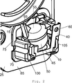
Die
In der
Der Sensor
Das Sensorglied
Zur Befestigung des Sensors
Der oder die Schnappelemente
Zur Befestigung des Trägerelements
Nach dem Einsetzen des Sensors
Bei dem Ausführungsbeispiel gemäß
Das Gehäuseteil
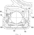
Die
Die
Die
Darüber hinaus zeigt die
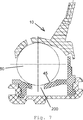
Die
Die
Die
Durch die Formgestaltung des ringförmigen, gewölbten Verbindungsabschnitts
Der Innenbereich
Die
Die
Der Winkel α ist vorzugsweise größer als 14° und beträgt beispielsweise 16°.The angle α is preferably greater than 14 ° and is for example 16 °.
BezugszeichenlisteLIST OF REFERENCE NUMBERS
- 11
- FahrzeugsicherheitseinrichtungVehicle safety device
- 55
- Gurtaufrollerretractor
- 1010
- Sensorsensor
- 1515
- Sperrradratchet wheel
- 2020
- Rahmenframe
- 2525
- Platteplate
- 3030
- DurchgangsöffnungThrough opening
- 3535
- Trägereinrichtungsupport means
- 4040
- Trägerelementsupport element
- 4545
- untere Rollflächelower rolling surface
- 5050
- Trägheitskörperinertial body
- 5555
- Sensorgliedsensor element
- 6060
- Bolzenbolt
- 6565
- Sperrabschnittblocking portion
- 7070
- Gehäuseteilhousing part
- 7575
- Anschlagsabschnittstop section
- 8080
- Schnappelementsnap element
- 8585
- dem Trägerelement zugewandte Seitethe carrier element facing side
- 9090
- dem Trägerelement abgewandte Seitethe side facing away from the carrier element
- 100100
- Schienenabschnittrail section
- 105105
- Schienenabschnittrail section
- 110110
- GehäuserückwandRear panel
- 120120
- Abdeckelementcover
- 150150
- Innenbereichinterior
- 155155
- Verbindungsabschnittconnecting portion
- 200200
- Bohrungdrilling
- 210210
- Konusflächeconical surface
- HH
- Horizontalehorizontal
- αα
- Winkelangle
- ββ
- Winkelangle
ZITATE ENTHALTEN IN DER BESCHREIBUNG QUOTES INCLUDE IN THE DESCRIPTION
Diese Liste der vom Anmelder aufgeführten Dokumente wurde automatisiert erzeugt und ist ausschließlich zur besseren Information des Lesers aufgenommen. Die Liste ist nicht Bestandteil der deutschen Patent- bzw. Gebrauchsmusteranmeldung. Das DPMA übernimmt keinerlei Haftung für etwaige Fehler oder Auslassungen.This list of the documents listed by the applicant has been generated automatically and is included solely for the better information of the reader. The list is not part of the German patent or utility model application. The DPMA assumes no liability for any errors or omissions.
Zitierte PatentliteraturCited patent literature
- DE 102008008041 A [0002] DE 102008008041 A [0002]
Claims (10)
Priority Applications (5)
| Application Number | Priority Date | Filing Date | Title |
|---|---|---|---|
| DE102011086656A DE102011086656A1 (en) | 2011-11-18 | 2011-11-18 | Sensor for triggering e.g. belt retractor in motor car, has housing portion made of softer material than carrier element and comprising snatching element, which performs snatching of housing rear wall in through hole of carrier device |
| JP2014541540A JP2014533621A (en) | 2011-11-18 | 2012-11-07 | Sensor |
| US14/357,493 US9409547B2 (en) | 2011-11-18 | 2012-11-07 | Sensor |
| PCT/DE2012/200071 WO2013071928A2 (en) | 2011-11-18 | 2012-11-07 | Sensor |
| EP12816450.6A EP2780201B1 (en) | 2011-11-18 | 2012-11-07 | Sensor |
Applications Claiming Priority (1)
| Application Number | Priority Date | Filing Date | Title |
|---|---|---|---|
| DE102011086656A DE102011086656A1 (en) | 2011-11-18 | 2011-11-18 | Sensor for triggering e.g. belt retractor in motor car, has housing portion made of softer material than carrier element and comprising snatching element, which performs snatching of housing rear wall in through hole of carrier device |
Publications (1)
| Publication Number | Publication Date |
|---|---|
| DE102011086656A1 true DE102011086656A1 (en) | 2012-05-03 |
Family
ID=45935873
Family Applications (1)
| Application Number | Title | Priority Date | Filing Date |
|---|---|---|---|
| DE102011086656A Ceased DE102011086656A1 (en) | 2011-11-18 | 2011-11-18 | Sensor for triggering e.g. belt retractor in motor car, has housing portion made of softer material than carrier element and comprising snatching element, which performs snatching of housing rear wall in through hole of carrier device |
Country Status (5)
| Country | Link |
|---|---|
| US (1) | US9409547B2 (en) |
| EP (1) | EP2780201B1 (en) |
| JP (1) | JP2014533621A (en) |
| DE (1) | DE102011086656A1 (en) |
| WO (1) | WO2013071928A2 (en) |
Cited By (3)
| Publication number | Priority date | Publication date | Assignee | Title |
|---|---|---|---|---|
| WO2017050794A1 (en) * | 2015-09-24 | 2017-03-30 | Autoliv Development Ab | Vehicle-sensitive sensor with multi-part sensor mass |
| DE102017203417A1 (en) | 2017-03-02 | 2018-09-06 | Autoliv Development Ab | Belt retractor with a noise-damped acceleration sensor |
| EP3848255A1 (en) * | 2020-01-08 | 2021-07-14 | Illinois Tool Works Inc. | Sensor housing for a sensor for detecting acceleration and / or tilt angle changes and sensor comprising such a sensor housing |
Families Citing this family (3)
| Publication number | Priority date | Publication date | Assignee | Title |
|---|---|---|---|---|
| JP6539102B2 (en) * | 2015-04-28 | 2019-07-03 | Joyson Safety Systems Japan株式会社 | Seat belt retractor and seat belt device |
| DE102020204949B4 (en) | 2020-04-20 | 2023-11-30 | Joyson Safety Systems Germany Gmbh | Sensor for a vehicle safety device |
| DE102020209902B3 (en) | 2020-08-05 | 2021-12-09 | Joyson Safety Systems Germany Gmbh | Sensor for a vehicle safety device |
Citations (1)
| Publication number | Priority date | Publication date | Assignee | Title |
|---|---|---|---|---|
| DE102008008041A1 (en) | 2008-02-05 | 2008-07-17 | Takata-Petri Ag | Belt retractor for seat belt, has mass inertia clutch arranged between drive pulley and belt spindle and mass inertia clutch has coupling element, which is swiveled by acceleration of driving wheel |
Family Cites Families (31)
| Publication number | Priority date | Publication date | Assignee | Title |
|---|---|---|---|---|
| DE2228683C2 (en) | 1972-06-13 | 1982-01-21 | Artur 7060 Schorndorf Föhl | Acceleration and deceleration dependent, electrical switching device for installation in vehicles |
| DE2646238C2 (en) | 1976-10-13 | 1989-02-23 | TRW Repa GmbH, 7077 Alfdorf | Belt retractors for vehicle seat belts |
| DE8009960U1 (en) * | 1980-04-11 | 1980-08-07 | Kolb Gmbh & Co, 8065 Erdweg | VEHICLE SENSITIVE BLOCKING DEVICE |
| DE8324794U1 (en) | 1983-08-30 | 1985-05-15 | Autoflug Gmbh, 2084 Rellingen | Self-locking belt retractor, in particular for motor vehicle seat belts |
| GB8404079D0 (en) * | 1984-02-16 | 1984-03-21 | Ase Uk Ltd | Seat belt retractor |
| DE8415088U1 (en) | 1984-05-17 | 1984-10-25 | Britax-Kolb GmbH & Co, 8065 Erdweg | BELT REEL FOR VEHICLE SAFETY BELTS |
| DE3418378A1 (en) | 1984-05-17 | 1986-02-13 | Britax-Kolb GmbH & Co, 8065 Erdweg | Belt retractor for vehicle safety belts |
| DE8436479U1 (en) | 1984-12-13 | 1986-04-17 | Autoflug Gmbh, 2084 Rellingen | Three-point seat belt arrangement |
| EP0185367B2 (en) | 1984-12-21 | 1993-03-24 | Autoliv-Kolb GmbH & Co. | Safety belt system |
| DE3446981A1 (en) | 1984-12-21 | 1986-09-18 | Britax-Kolb GmbH & Co, 8060 Dachau | CLAMPING DEVICE FOR A SAFETY BELT SYSTEM |
| JPH01307671A (en) | 1988-06-07 | 1989-12-12 | Takata Kk | Acceleration induction device |
| US5209421A (en) | 1990-09-27 | 1993-05-11 | Fuji-Autolib Co., Ltd. | Noiseless emergency locking type retractor |
| US5178410A (en) * | 1991-06-14 | 1993-01-12 | Breed Automotive Technology, Inc. | Velocity change sensor with lateral shock absorber |
| DE9110281U1 (en) | 1991-08-20 | 1991-10-17 | TRW Repa GmbH, 7077 Alfdorf | Noise-damped sensor for a seat belt retractor |
| GB9215855D0 (en) | 1992-07-25 | 1992-09-09 | Bsrd Ltd | Improvements to emergency locking passenger safety belt mechanisms |
| GB2278894B (en) | 1993-05-26 | 1997-12-24 | Luk Lamellen & Kupplungsbau | Friction clutch |
| US5495994A (en) * | 1994-09-07 | 1996-03-05 | Trw Vehicle Safety Systems Inc. | Inertia sensitive seat belt retractor |
| JPH10181526A (en) * | 1996-12-20 | 1998-07-07 | Tokai Rika Co Ltd | Acceleration sensor device for vehicle |
| US6082655A (en) | 1998-11-04 | 2000-07-04 | Trw Vehicle Safety Systems Inc. | Noise suppression cover for belt webbing retractor |
| US6164581A (en) * | 1999-01-29 | 2000-12-26 | Breed Automotive Technology, Inc. | Low noise self-compensating vehicle sensor and retractor |
| JP3645445B2 (en) | 1999-04-09 | 2005-05-11 | 株式会社東海理化電機製作所 | Webbing take-up device |
| US6419178B1 (en) | 2000-07-19 | 2002-07-16 | Breed Automotive Technology, Inc. | Seat belt retractor with integrally formed frame |
| JP3984061B2 (en) | 2002-01-25 | 2007-09-26 | 芦森工業株式会社 | Seat belt retractor |
| DE10227788A1 (en) | 2002-06-21 | 2004-01-08 | Trw Occupant Restraint Systems Gmbh & Co. Kg | Sensor for a belt retractor |
| DE10230211B4 (en) | 2002-07-04 | 2004-07-29 | Autoliv Development Ab | Vehicle sensor for a belt retractor with a stepped footprint |
| DE102005032808A1 (en) | 2004-12-13 | 2007-01-18 | Krohne Ag | gauge |
| BRPI0604333A (en) * | 2006-10-23 | 2008-06-17 | Chris Cintos De Seguranca Ltda | seat belt vibration / noise absorption system |
| DE102007049200B4 (en) | 2007-10-13 | 2023-10-05 | Autoliv Development Ab | Self-locking belt retractor |
| DE102009018177B4 (en) | 2009-04-22 | 2019-08-14 | Autoliv Development Ab | Belt retractor with a noise-damped acceleration sensor |
| DE102009036516B4 (en) | 2009-08-07 | 2021-07-15 | Autoliv Development Ab | Self-locking belt retractor |
| JP2011111007A (en) * | 2009-11-25 | 2011-06-09 | Takata Corp | Seat belt retractor and seat belt device |
-
2011
- 2011-11-18 DE DE102011086656A patent/DE102011086656A1/en not_active Ceased
-
2012
- 2012-11-07 US US14/357,493 patent/US9409547B2/en active Active
- 2012-11-07 JP JP2014541540A patent/JP2014533621A/en active Pending
- 2012-11-07 WO PCT/DE2012/200071 patent/WO2013071928A2/en active Application Filing
- 2012-11-07 EP EP12816450.6A patent/EP2780201B1/en active Active
Patent Citations (1)
| Publication number | Priority date | Publication date | Assignee | Title |
|---|---|---|---|---|
| DE102008008041A1 (en) | 2008-02-05 | 2008-07-17 | Takata-Petri Ag | Belt retractor for seat belt, has mass inertia clutch arranged between drive pulley and belt spindle and mass inertia clutch has coupling element, which is swiveled by acceleration of driving wheel |
Cited By (6)
| Publication number | Priority date | Publication date | Assignee | Title |
|---|---|---|---|---|
| WO2017050794A1 (en) * | 2015-09-24 | 2017-03-30 | Autoliv Development Ab | Vehicle-sensitive sensor with multi-part sensor mass |
| EP3459797A1 (en) | 2015-09-24 | 2019-03-27 | Autoliv Development AB | Vehicle-sensitive sensor with multi-part sensor mass |
| US10793104B2 (en) | 2015-09-24 | 2020-10-06 | Autoliv Development Ab | Vehicle-sensitive sensor with multi-part sensor mass |
| DE102017203417A1 (en) | 2017-03-02 | 2018-09-06 | Autoliv Development Ab | Belt retractor with a noise-damped acceleration sensor |
| DE102017203417B4 (en) * | 2017-03-02 | 2020-09-10 | Autoliv Development Ab | Belt retractor with a noise-dampened acceleration sensor |
| EP3848255A1 (en) * | 2020-01-08 | 2021-07-14 | Illinois Tool Works Inc. | Sensor housing for a sensor for detecting acceleration and / or tilt angle changes and sensor comprising such a sensor housing |
Also Published As
| Publication number | Publication date |
|---|---|
| WO2013071928A3 (en) | 2013-07-11 |
| US9409547B2 (en) | 2016-08-09 |
| JP2014533621A (en) | 2014-12-15 |
| EP2780201B1 (en) | 2016-01-13 |
| EP2780201A2 (en) | 2014-09-24 |
| WO2013071928A2 (en) | 2013-05-23 |
| US20140305203A1 (en) | 2014-10-16 |
Similar Documents
| Publication | Publication Date | Title |
|---|---|---|
| EP2780201B1 (en) | Sensor | |
| EP0528230A2 (en) | Soundproofed sensor for a safety belt retractor | |
| DE102011008339B4 (en) | Device for removing vibrations on a vehicle part | |
| DE102013104144A1 (en) | Door structure with a locking element preventing the door unlocking | |
| EP3353017B1 (en) | Vehicle-sensitive sensor with multi-part sensor mass | |
| DE102018101737A1 (en) | Biegefederelement made of fiber-reinforced plastic composite material | |
| DE102014115704A1 (en) | Motor vehicle door lock | |
| AT517290A2 (en) | axle spring | |
| DE102007049200B4 (en) | Self-locking belt retractor | |
| DE112018006035T5 (en) | ULTRASONIC SENSOR AND BRACKET | |
| EP1564432B1 (en) | Spring assembly for a vehicle and a spring seat for such a spring assembly | |
| DE102009018177B4 (en) | Belt retractor with a noise-damped acceleration sensor | |
| DE102006033543B4 (en) | Self-locking belt retractor | |
| DE102017203417B4 (en) | Belt retractor with a noise-dampened acceleration sensor | |
| DE102018128163A1 (en) | Wheel house for a motor vehicle | |
| DE102008039215A1 (en) | Sensor, particularly for triggering vehicle occupant restraint system, has lower rolling surface, where lower area of lower rolling surface has elevation, which is arranged to guide rolling inertia body around elevation | |
| DE102015118087A1 (en) | bumper assembly | |
| DE19949369C2 (en) | Attachment of a trim part to a wall element | |
| DE102011008289A1 (en) | Vehicle has bumper bracket and bumper unit, where baffle element and detection unit are arranged between bumper bracket and bumper unit | |
| DE102015017201B4 (en) | Vehicle-sensitive sensor with multi-part sensor mass | |
| DE29615567U1 (en) | Front protection bar | |
| DE10003917B4 (en) | Holding device for a decorative figure of a motor vehicle | |
| EP1033297A2 (en) | Dynamic damper for steering wheels of motor vehicles | |
| EP2343221A1 (en) | Rollover protection for motor vehicles | |
| DE102010036296A1 (en) | Arrangement for fastening a steering column to a vehicle-mounted component of a vehicle |
Legal Events
| Date | Code | Title | Description |
|---|---|---|---|
| R012 | Request for examination validly filed | ||
| R230 | Request for early publication | ||
| R082 | Change of representative |
Representative=s name: UWE FISCHER, DE |
|
| R081 | Change of applicant/patentee |
Owner name: TAKATA AKTIENGESELLSCHAFT, DE Free format text: FORMER OWNER: TAKATA-PETRI AG, 63743 ASCHAFFENBURG, DE Effective date: 20120904 |
|
| R082 | Change of representative |
Representative=s name: FISCHER, UWE, DIPL.-ING. DR.-ING., DE Effective date: 20120904 Representative=s name: UWE FISCHER, DE Effective date: 20120904 |
|
| R016 | Response to examination communication | ||
| R002 | Refusal decision in examination/registration proceedings | ||
| R003 | Refusal decision now final |