DE102004040775B4 - packaging tray - Google Patents
packaging tray Download PDFInfo
- Publication number
- DE102004040775B4 DE102004040775B4 DE102004040775.4A DE102004040775A DE102004040775B4 DE 102004040775 B4 DE102004040775 B4 DE 102004040775B4 DE 102004040775 A DE102004040775 A DE 102004040775A DE 102004040775 B4 DE102004040775 B4 DE 102004040775B4
- Authority
- DE
- Germany
- Prior art keywords
- packaging tray
- tray
- packaging
- depressions
- shell
- Prior art date
- Legal status (The legal status is an assumption and is not a legal conclusion. Google has not performed a legal analysis and makes no representation as to the accuracy of the status listed.)
- Expired - Fee Related
Links
- 238000004806 packaging method and process Methods 0.000 title claims abstract description 59
- 235000013372 meat Nutrition 0.000 claims abstract description 4
- 230000002745 absorbent Effects 0.000 claims description 14
- 239000002250 absorbent Substances 0.000 claims description 14
- 235000013305 food Nutrition 0.000 claims description 6
- 238000003466 welding Methods 0.000 claims description 5
- 239000004033 plastic Substances 0.000 claims description 4
- 239000004743 Polypropylene Substances 0.000 claims description 3
- -1 polypropylene Polymers 0.000 claims description 3
- 229920001155 polypropylene Polymers 0.000 claims description 3
- 238000003856 thermoforming Methods 0.000 claims description 3
- 239000004793 Polystyrene Substances 0.000 claims description 2
- XAGFODPZIPBFFR-UHFFFAOYSA-N aluminium Chemical compound [Al] XAGFODPZIPBFFR-UHFFFAOYSA-N 0.000 claims description 2
- 229910052782 aluminium Inorganic materials 0.000 claims description 2
- 229920002223 polystyrene Polymers 0.000 claims description 2
- 230000007704 transition Effects 0.000 claims description 2
- 238000012856 packing Methods 0.000 claims 1
- 239000002689 soil Substances 0.000 claims 1
- 239000007788 liquid Substances 0.000 description 6
- 238000004519 manufacturing process Methods 0.000 description 2
- 230000002093 peripheral effect Effects 0.000 description 2
- 239000011358 absorbing material Substances 0.000 description 1
- 230000007423 decrease Effects 0.000 description 1
- 239000012530 fluid Substances 0.000 description 1
- 239000000463 material Substances 0.000 description 1
- 235000021485 packed food Nutrition 0.000 description 1
- 230000008092 positive effect Effects 0.000 description 1
- 230000003134 recirculating effect Effects 0.000 description 1
- 238000007789 sealing Methods 0.000 description 1
- 239000012780 transparent material Substances 0.000 description 1
- 238000009423 ventilation Methods 0.000 description 1
Images
Classifications
-
- B—PERFORMING OPERATIONS; TRANSPORTING
- B65—CONVEYING; PACKING; STORING; HANDLING THIN OR FILAMENTARY MATERIAL
- B65D—CONTAINERS FOR STORAGE OR TRANSPORT OF ARTICLES OR MATERIALS, e.g. BAGS, BARRELS, BOTTLES, BOXES, CANS, CARTONS, CRATES, DRUMS, JARS, TANKS, HOPPERS, FORWARDING CONTAINERS; ACCESSORIES, CLOSURES, OR FITTINGS THEREFOR; PACKAGING ELEMENTS; PACKAGES
- B65D81/00—Containers, packaging elements, or packages, for contents presenting particular transport or storage problems, or adapted to be used for non-packaging purposes after removal of contents
- B65D81/24—Adaptations for preventing deterioration or decay of contents; Applications to the container or packaging material of food preservatives, fungicides, pesticides or animal repellants
- B65D81/26—Adaptations for preventing deterioration or decay of contents; Applications to the container or packaging material of food preservatives, fungicides, pesticides or animal repellants with provision for draining away, or absorbing, or removing by ventilation, fluids, e.g. exuded by contents; Applications of corrosion inhibitors or desiccators
- B65D81/264—Adaptations for preventing deterioration or decay of contents; Applications to the container or packaging material of food preservatives, fungicides, pesticides or animal repellants with provision for draining away, or absorbing, or removing by ventilation, fluids, e.g. exuded by contents; Applications of corrosion inhibitors or desiccators for absorbing liquids
Landscapes
- Engineering & Computer Science (AREA)
- Food Science & Technology (AREA)
- Mechanical Engineering (AREA)
- Packages (AREA)
- Containers Having Bodies Formed In One Piece (AREA)
- Packging For Living Organisms, Food Or Medicinal Products That Are Sensitive To Environmental Conditiond (AREA)
Abstract
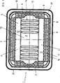
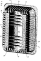
Verpackungsschale (1) für Lebensmittel, insbesondere Frischfleisch, die in Aufsicht eine in etwa rechteckige oder quadratische Form besitzt, mit einem Schalenboden (3) und mit einer sich vom Schalenboden (3) nach oben erstreckenden, umlaufenden Seitenwand (2), wobei zwischen dem Schalenboden (3) und der Seitenwand (2) eine Vertiefung (11) zum Einlegen einer Saugeinlage (5) angeordnet ist, zwei in Aufsicht streifenförmige Vertiefungen (11) vorhanden sind, die parallel zueinander verlaufen und sich eine Vertiefung (11) entlang einer Längsseite (7) der Verpackungsschale (1) erstreckt während sich die andere Vertiefung (11) entlang der gegenüberliegenden Längsseite (8) der Verpackungsschale (1) erstreckt, dadurch gekennzeichnet, dass der Schalenboden (3) zwischen den beiden Vertiefungen (11) kuppelförmig derart nach oben gewölbt ist, dass er beidseitig zu den Vertiefungen (11) hin abfällt, und dass im Schalenboden (3) mindestens eine Rinne (14) ausgebildet ist, deren Boden (15) höher liegt als der Boden (12) der Vertiefungen (11) und die in die Vertiefungen (11) mündet.Packaging tray (1) for foodstuffs, in particular fresh meat, which has an approximately rectangular or square shape in plan view, with a tray bottom (3) and with a circumferential side wall (2) extending upwardly from the tray bottom (3), between the Shell bottom (3) and the side wall (2) has a recess (11) for inserting a suction insert (5) is arranged, two in plan strip-shaped depressions (11) are present, which are parallel to each other and a depression (11) along a longitudinal side (7) the packaging shell (1) extends while the other depression (11) extends along the opposite longitudinal side (8) of the packaging shell (1), characterized in that the shell bottom (3) dome - shaped in such a manner between the two depressions (11) is curved above that it falls on both sides of the recesses (11) out, and that in the tray bottom (3) at least one channel (14) is formed, the bottom (15) h here lies than the bottom (12) of the recesses (11) and into the recesses (11) opens.
Description
Die Erfindung betrifft eine Verpackungsschale für Lebensmittel, insbesondere Frischfleisch, die in Aufsicht eine in etwa rechteckige oder quadratische Form besitzt, mit einem Schalenboden und mit einer sich vom Schalenboden nach oben erstreckenden umlaufenden Seitenwand, wobei zwischen dem Schalenboden und der Seitenwand eine Vertiefung zum Einlegen einer Saugeinlage angeordnet ist. zwei in Aufsicht streifenförmige Vertiefungen vorhanden sind, die parallel zueinander verlaufen, und sich eine Vertiefung entlang einer Längsseite der Verpackungsschale erstreckt während sich die andere Vertiefung entlang der gegenüberliegenden Längsseite der Verpackungsschale erstreckt.The invention relates to a packaging tray for food, especially fresh meat, which has an approximately rectangular or square shape in plan view, with a shell bottom and with a shell bottom upwardly extending circumferential side wall, wherein between the shell bottom and the side wall a recess for inserting a Suction pad is arranged. two in plan strip-shaped recesses are provided which are parallel to each other, and a recess extends along one longitudinal side of the packaging tray while the other recess extends along the opposite longitudinal side of the packaging tray.
Es sind bereits zahlreiche Verpackungsschalen bekannt, die mit einer Saugeinlage ausgerüstet sind, um die von dem verpackten Nahrungsmittel abgesonderten Flüssigkeiten zu absorbieren. Diesbezüglich wird beispielsweise verwiesen auf das deutsche Gebrauchsmuster
Eine der weiteren gattungsgemäßen Verpackungsschale mit einer gerippten Seitenstruktur ist aus dem
Auch das deutsche Gebrauchsmuster
In der
Aufgabe der vorliegenden Erfindung ist es daher, eine verbesserte Verpackungsschale der genannten Art bereitzustellen, die in Großserie einfacher herstellbar ist und in welche die Saugeinlage auf einfache Weise eingebracht werden kann.Object of the present invention is therefore to provide an improved packaging tray of the type mentioned, which is easier to produce in mass production and in which the absorbent pad can be introduced in a simple manner.
Gelöst wird diese Aufgabe durch eine Verpackungsschale gemäß der Lehre des Anspruchs 1.This problem is solved by a packaging tray according to the teaching of
Die erfindungsgemäße Verpackungsschale besitzt zwei in Aufsicht streifenförmige Vertiefungen, die parallel zueinander verlaufen. Eine dieser Vertiefungen verläuft dabei entlang einer Längsseite der Verpackungsschale, während sich die andere Vertiefung entlang der gegenüberliegenden Längsseite der Verpackungsschale erstreckt. Diese Vertiefungen befinden sich somit zwischen dem Schalenboden und der Seitenwand. Besitzt die Verpackungsschale in Aufsicht eine rechteckige Form, dann können sich die Vertiefungen entlang der größeren Längsseite (nachstehend Längsseite genannt) und auch entlang der kürzeren Längsseite (nachstehend Querseite genannt) erstrecken.The packaging tray according to the invention has two in plan view strip-shaped depressions which are parallel to each other. One of these depressions runs along one longitudinal side of the packaging shell, while the other depression extends along the opposite longitudinal side of the packaging shell. These recesses are thus between the shell bottom and the side wall. If the packaging tray has a rectangular shape in plan view, then the depressions may extend along the larger longitudinal side (hereinafter referred to as longitudinal side) and also along the shorter longitudinal side (hereinafter referred to as transverse side).
Die erfindungsgemäße Verpackungsschale zeichnet sich dadurch aus, dass der Schalenboden zwischen den beiden Vertiefungen kuppelförmig derart nach oben gewölbt, dass er beidseitig zu den Vertiefungen hin abfällt. Auf diese Weise werden die von dem verpackten Gut abgesonderte Flüssigkeiten zu den Vertiefungen und den darin befindlichen Saugeinlagen geleitet. Besteht die Verpackungsschale aus einem durchsichtigen Material, was vorzugsweise der Fall ist, dann kann das verpackte Gut durch den Schalenboden vom Kunden begutachtet werden, ohne dass abgesonderte Flüssigkeiten den ästhetischen Eindruck beeinflussen.The packaging tray according to the invention is characterized in that the tray bottom between the two wells dome-shaped curved so upwards that it falls off on both sides to the wells out. In this way, the separated liquids from the packaged Good are passed to the wells and the suction pads therein. If the packaging tray is made of a transparent material, which is preferably the case, then the packaged product can be inspected by the tray bottom by the customer, without any secreted liquids influencing the aesthetic impression.
Die erfindungsgemäße Verpackungsschale zeichnet sich ferner dadurch aus, dass im gewölbten Bereich des Schalenbodens mindestens eine Rinne ausgebildet ist, deren Boden nicht tiefer liegt als der Boden der Vertiefungen und die in die Vertiefungen mündet. Auf diese Weise können abgesonderte Flüssigkeiten besser zu den Vertiefungen abgeleitet werden. Ferner ist dadurch auch eine Belüftung des verpackten Gutes möglich.The packaging tray according to the invention is further distinguished by the fact that at least one channel is formed in the arched area of the tray bottom, the bottom of which is not lower than the bottom of the recesses and which opens into the recesses. In this way, separated liquids can be better diverted to the wells. Furthermore, this also ventilation of the packaged goods is possible.
Nach einer bevorzugten Ausführungsform wird eine streifenförmige Saugeinlage eingesetzt. Derartige Saugeinlagen können in schmalen Streifen von Standardrollen geschnitten werden und mit der Verpackungsschale, vorzugsweise mit dem Boden der Vertiefung, verbunden und somit daran fixiert werden. Diese Fixierung erfolgt vorzugsweise durch Ultraschallschweißen und erfolgt weiterhin vorzugsweise punktuell oder entlang von Linien. Nach einer am meisten bevorzugten Ausführungsform ist die Saugeinlage an ihren Endpunkten an dem Boden der Vertiefung fixiert. Eine derartige Fixierung mittels Ultraschallschweißen ist in dem
Nach einer weiteren bevorzugten Ausführungsform ist der Boden der Vertiefungen plan. Zudem liegen die Böden der beiden Vertiefungen in etwa auf gleicher Höhe. Dadurch liegt die Saugeinlage optimal auf dem Boden der Vertiefung auf und verbindet sich nicht an dem jeweiligen in der Verpackungsschale liegenden Gut und kann somit auch nicht herausgerissen werden. According to another preferred embodiment, the bottom of the wells is flat. In addition, the bottoms of the two wells are approximately at the same height. As a result, the absorbent pad lies optimally on the bottom of the depression and does not connect to the respective material lying in the packaging shell and thus can not be torn out.
Sofern dies wegen der aufzunehmenden Flüssigkeitsmenge erforderlich ist, werden zwei Lagen einer derartigen Saugeinlage eingelegt und insbesondere eingeschweißt.If this is necessary because of the amount of liquid to be absorbed, two layers of such absorbent insert are inserted and in particular welded.
Vorzugsweise sind mehrere Rinnen vorhanden, die parallel zueinander verlaufen sowie senkrecht zu den Vertiefungen angeordnet sind. Dadurch können die oben erwähnten positiven Effekte noch gesteigert werden.Preferably, a plurality of grooves are present, which run parallel to each other and are arranged perpendicular to the recesses. As a result, the above-mentioned positive effects can be increased even more.
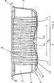
Nach einer bevorzugten Ausführungsform bildet der Übergang zwischen den Vertiefungen und dem Schalenboden in dem Bereich, in dem keine Vertiefungen vorhanden sind, und der Seitenwand einen abgerundeten Wandbereich, in dem zumindest bereichsweise im wesentlichen nebeneinander angeordnete und zum Inneren der Schale offene Kanäle vorhanden sind, die sich in etwa senkrecht zur Längsrichtung des Randbereiches erstrecken. Der Kanalboden dieser Kanäle liegt an deren dem Schalenboden zugesandten Ende nicht tiefer als der Boden der Vertiefungen. Daher ergibt sich eine Rippenstruktur, die in dem
Zumindest einige Kanäle im Randbereich gehen zur Seitenwand hin in zum Inneren der Schale offene, im wesentlichen nebeneinander angeordnete Seitenkanäle über, die sich im wesentlichen senkrecht ausgehend vom Randbereich nach oben in der Seitenwand erstrecken. Auch diese Struktur ist aus dem genannten Gebrauchsmuster bekannt. Die Seitenkanäle verringern sich dabei vorzugsweise vom Randbereich aus zu ihrem jeweiligen Ende hin in ihrer Tiefe und/oder ihrer Breite.At least some channels in the edge region pass over to the side wall into side channels which are open to the interior of the shell and essentially extend next to one another, which extend substantially perpendicularly from the edge region upwards in the side wall. This structure is known from the aforementioned utility model. The side channels are preferably reduced from the edge region to their respective end in their depth and / or their width.
Die erfindungsgemäße Verpackungsschale ist vorzugsweise einstückig und durch Tiefziehen einer Folie erhältlich. Bei der Folie handelt es sich vorzugsweise um eine solche aus Kunststoff oder Aluminium. Bei dem Kunststoff kann es sich beispielsweise um Polypropylen oder Polystyrol handeln. Die Verpackungsschale wird insbesondere durch Thermoformen hergestellt.The packaging tray according to the invention is preferably in one piece and obtainable by deep-drawing a film. The film is preferably one made of plastic or aluminum. The plastic may be, for example, polypropylene or polystyrene. The packaging tray is produced in particular by thermoforming.
Die Erfindung wird im folgenden anhand der Zeichnungen näher erläutert.The invention will be explained in more detail below with reference to the drawings.
Die in der
Der Schalenboden
Die Vertiefungen
Zwischen den beiden Vertiefungen
In diesem Gewölbe
Befindet sich eine flüssigkeitsabsondernde Fleischeinlage in der Verpackungsschale
In dem Gewölbe
Insbesondere aus den
Die Seitenwand
Sowohl die Kanäle
Durch diese nebeneinander liegenden Kanäle
Die umlaufende Seitenwand
Die in den Figuren gezeigte Verpackungsschale
Die unteren, äußeren Mantelflächen der Vertiefungen
BezugszeichenlisteLIST OF REFERENCE NUMBERS
- 11
- Verpackungsschalepackaging tray
- 22
- SeitenwandSide wall
- 33
- Schalenbodenshell bottom
- 44
- Randbereichborder area
- 55
- Saugeinlageabsorbent panel
- 66
- Seitenkanalside channel
- 77
- Längsseitelong side
- 88th
- Längsseitelong side
- 99
- Querseitetransverse side
- 1010
- Querseitetransverse side
- 1111
- Vertiefungdeepening
- 1212
- Bodenground
- 1313
- Gewölbevault
- 1414
- Rinnegutter
- 1515
- Rinnenbodenchannel base
- 1616
- Kanalchannel
- 1717
- Kanalbodenchannel bottom
- 1818
- Randedge
- 1919
- Siegelrandsealing edge
Claims (14)
Priority Applications (2)
| Application Number | Priority Date | Filing Date | Title |
|---|---|---|---|
| DE102004040775.4A DE102004040775B4 (en) | 2004-08-23 | 2004-08-23 | packaging tray |
| EP05018275A EP1630107A3 (en) | 2004-08-23 | 2005-08-23 | packaging tray |
Applications Claiming Priority (1)
| Application Number | Priority Date | Filing Date | Title |
|---|---|---|---|
| DE102004040775.4A DE102004040775B4 (en) | 2004-08-23 | 2004-08-23 | packaging tray |
Publications (2)
| Publication Number | Publication Date |
|---|---|
| DE102004040775A1 DE102004040775A1 (en) | 2006-03-02 |
| DE102004040775B4 true DE102004040775B4 (en) | 2015-09-10 |
Family
ID=35427612
Family Applications (1)
| Application Number | Title | Priority Date | Filing Date |
|---|---|---|---|
| DE102004040775.4A Expired - Fee Related DE102004040775B4 (en) | 2004-08-23 | 2004-08-23 | packaging tray |
Country Status (2)
| Country | Link |
|---|---|
| EP (1) | EP1630107A3 (en) |
| DE (1) | DE102004040775B4 (en) |
Families Citing this family (1)
| Publication number | Priority date | Publication date | Assignee | Title |
|---|---|---|---|---|
| DE202011050589U1 (en) | 2011-06-30 | 2011-10-14 | Es-Plastic Gmbh & Co. Kg | Bowl for skewers |
Citations (7)
| Publication number | Priority date | Publication date | Assignee | Title |
|---|---|---|---|---|
| DE9109537U1 (en) * | 1990-09-06 | 1991-09-26 | Bartling-Werke Friedr.-Aug. Bartling GmbH & Co. KG, 4714 Selm | Packaging tray for food |
| DE69300866T2 (en) * | 1992-01-27 | 1996-07-18 | Andersen Irma | PACKING TRAY FOR LIQUID FOODSTUFFS LIKE MEAT. |
| DE69705852T2 (en) * | 1996-10-23 | 2002-04-04 | Actuant Corp., Glendale | HYDRAULIC SYSTEM FOR TILTING A DRIVER'S CAB |
| DE29924308U1 (en) * | 1998-09-15 | 2002-09-19 | Pedersen, Steen, Esbjerg V | packaging tray |
| DE20308312U1 (en) * | 2003-05-27 | 2003-07-24 | ES-Plastic GmbH & Co. KG, 94116 Hutthurm | Packing tray for fresh food has channels provided in rounded edge section connecting side wall to base, are towards inside of tray, and extend perpendicularly to longitudinal direction of edge section |
| US20030141307A1 (en) * | 2001-10-26 | 2003-07-31 | Craig Sanders | Tray for storing and transporting products |
| DE20312305U1 (en) * | 2003-08-09 | 2003-12-04 | Neid, Oliver | Food storage and vending pack has a groove around the inside of the base and filled with a moisture absorbing insert |
Family Cites Families (3)
| Publication number | Priority date | Publication date | Assignee | Title |
|---|---|---|---|---|
| DE1061965B (en) | 1957-01-17 | 1959-07-23 | Colex Andresen K G | Shaped body made from bath salt bubbling in water |
| US3155303A (en) * | 1962-01-31 | 1964-11-03 | Fred Minikes | Meat packaging tray |
| DE10061965B4 (en) * | 2000-12-13 | 2004-08-19 | Es-Plastic Gmbh & Co.Kg | Packaging tray for food and process for its production |
-
2004
- 2004-08-23 DE DE102004040775.4A patent/DE102004040775B4/en not_active Expired - Fee Related
-
2005
- 2005-08-23 EP EP05018275A patent/EP1630107A3/en not_active Withdrawn
Patent Citations (7)
| Publication number | Priority date | Publication date | Assignee | Title |
|---|---|---|---|---|
| DE9109537U1 (en) * | 1990-09-06 | 1991-09-26 | Bartling-Werke Friedr.-Aug. Bartling GmbH & Co. KG, 4714 Selm | Packaging tray for food |
| DE69300866T2 (en) * | 1992-01-27 | 1996-07-18 | Andersen Irma | PACKING TRAY FOR LIQUID FOODSTUFFS LIKE MEAT. |
| DE69705852T2 (en) * | 1996-10-23 | 2002-04-04 | Actuant Corp., Glendale | HYDRAULIC SYSTEM FOR TILTING A DRIVER'S CAB |
| DE29924308U1 (en) * | 1998-09-15 | 2002-09-19 | Pedersen, Steen, Esbjerg V | packaging tray |
| US20030141307A1 (en) * | 2001-10-26 | 2003-07-31 | Craig Sanders | Tray for storing and transporting products |
| DE20308312U1 (en) * | 2003-05-27 | 2003-07-24 | ES-Plastic GmbH & Co. KG, 94116 Hutthurm | Packing tray for fresh food has channels provided in rounded edge section connecting side wall to base, are towards inside of tray, and extend perpendicularly to longitudinal direction of edge section |
| DE20312305U1 (en) * | 2003-08-09 | 2003-12-04 | Neid, Oliver | Food storage and vending pack has a groove around the inside of the base and filled with a moisture absorbing insert |
Also Published As
| Publication number | Publication date |
|---|---|
| EP1630107A3 (en) | 2006-04-12 |
| EP1630107A2 (en) | 2006-03-01 |
| DE102004040775A1 (en) | 2006-03-02 |
Similar Documents
| Publication | Publication Date | Title |
|---|---|---|
| DE69500053T2 (en) | Packaging for packaging and preserving fresh goods | |
| CH627987A5 (en) | STACKABLE BOTTLE BOX MADE OF PLASTIC. | |
| DE2703278A1 (en) | PACKAGING TRAY | |
| DE2944327A1 (en) | TRAY FOR MUG | |
| DE3530350C2 (en) | ||
| DE3722789C2 (en) | ||
| DE3737052C2 (en) | ||
| DE2428960C2 (en) | Bowl-shaped flat container made of pressed material | |
| DE60018458T2 (en) | PRESS FORM FOODS SUCH AS HAM DURING THEIR COOKING CONTAINED CONTAINING PRESSURE | |
| DE3202032C2 (en) | Multi-layer bag open on one side for holding powdery products | |
| DE19856494C2 (en) | Tray for packaging meat portions or similar foods | |
| DE102004040775B4 (en) | packaging tray | |
| DE2357979A1 (en) | BOTTLE PACKAGING | |
| DE7118186U (en) | Tray for packing meat and the like. | |
| EP3875399A1 (en) | Packaging tray with bottom tray | |
| DE202008005727U1 (en) | Packaging bag, sealing jaw arrangement | |
| DE29711265U1 (en) | Product carrier for food packaging | |
| DE102009011312A1 (en) | Collapsible container, has cover foils connected at upper and/or lower edges by bridging interspaces of foils such that bearing forces obtained from side walls are perpendicularly guided to upper and/or lower edges | |
| DE102006025198A1 (en) | System box especially for the transport of fresh fish | |
| DE29716844U1 (en) | Food holding tray | |
| DE20308312U1 (en) | Packing tray for fresh food has channels provided in rounded edge section connecting side wall to base, are towards inside of tray, and extend perpendicularly to longitudinal direction of edge section | |
| DE3916668A1 (en) | Carrying tray for fruit and horticultural fruits | |
| DE3302191A1 (en) | CONTAINER, IN PARTICULAR MENU BOWL IN ALUMINUM FILM, WITH LID | |
| DE3841806A1 (en) | Stackable bottle crate made of plastic | |
| DE2743709A1 (en) | PACKAGING AND METHOD AND DEVICE FOR THEIR MANUFACTURING |
Legal Events
| Date | Code | Title | Description |
|---|---|---|---|
| R005 | Application deemed withdrawn due to failure to request examination | ||
| R409 | Internal rectification of the legal status completed | ||
| R074 | Re-establishment allowed | ||
| R409 | Internal rectification of the legal status completed | ||
| R012 | Request for examination validly filed |
Effective date: 20110823 |
|
| R016 | Response to examination communication | ||
| R016 | Response to examination communication | ||
| R018 | Grant decision by examination section/examining division | ||
| R081 | Change of applicant/patentee |
Owner name: ES-PLASTIK GMBH, DE Free format text: FORMER OWNER: ES-PLASTIC GMBH & CO.KG, 94116 HUTTHURM, DE |
|
| R082 | Change of representative |
Representative=s name: PROPINDUS PATENTANWAELTE NIEDMERS JAEGER KOEST, DE |
|
| R119 | Application deemed withdrawn, or ip right lapsed, due to non-payment of renewal fee |