CN216540582U - Elastic strip blank conveying system - Google Patents
Elastic strip blank conveying system Download PDFInfo
- Publication number
- CN216540582U CN216540582U CN202123235995.4U CN202123235995U CN216540582U CN 216540582 U CN216540582 U CN 216540582U CN 202123235995 U CN202123235995 U CN 202123235995U CN 216540582 U CN216540582 U CN 216540582U
- Authority
- CN
- China
- Prior art keywords
- conveying belt
- guide plate
- elastic strip
- strip blank
- conveyer belt
- Prior art date
- Legal status (The legal status is an assumption and is not a legal conclusion. Google has not performed a legal analysis and makes no representation as to the accuracy of the status listed.)
- Active
Links
Images


Abstract
The utility model provides an elastic strip blank conveying system which comprises a first conveying belt, a second conveying belt and a third conveying belt which are sequentially butted, wherein the first conveying belt is butted with a cutting device, the first conveying belt conveys an elastic strip blank onto the second conveying belt through a first butting unit, the second conveying belt is in matched butt joint with at least one third conveying belt, the third conveying belt is connected with the second conveying belt through a second butting unit, and the second conveying belt is butted with a heating forming device. The utility model has the advantages that: the cooperation through a plurality of conveyer belts and butt joint unit carries the bullet strip blank of cutting in with cutting equipment for thermoforming equipment, can guarantee the continuation of takt time, and the second conveyer belt can dock a plurality of third conveyer belts simultaneously moreover to use a cutting equipment to dock a plurality of thermoforming equipment, make cutting equipment can efficient work, improve production efficiency.
Description
Technical Field
The utility model relates to the technical field of elastic strip processing, in particular to an elastic strip blank conveying system.
Background
The bullet strip is the part of the fixed rail of widely used in the rail is laid, and the bullet strip is processed man-hour at the mill, generally is to send into the structure that rear end equipment heated and crooked bullet strip into after cutting into the length of predetermineeing, because cutting equipment and the unable direct butt joint of firing equipment, therefore mainly carry out the transportation of raw materials through the manual type among the prior art, need consume higher human cost, work efficiency is lower moreover.
The schemes such as the automatic stacking device disclosed in the utility model patent application with publication number CN111071803A and the elastic bar collecting and grabbing device disclosed in the utility model patent with publication number CN209939846U can be used for transferring the cut raw materials of the cutting equipment to the thermoforming equipment, however, these equipments all need to perform the discontinuous material transferring operation, which can affect the normal production rhythm and the production efficiency, and the transferred materials can not be ensured to enter the thermoforming equipment in sequence in a regular arrangement, and still need to be manually operated or assisted; and generally, the time required for cutting is far shorter than the time required for heating and bending forming, and if the elastic strip blank output by the cutting equipment is directly conveyed to the heating forming equipment, the working efficiency of the cutting equipment is seriously influenced.
SUMMERY OF THE UTILITY MODEL
The utility model aims to provide an elastic strip blank conveying system which can automatically convey cut elastic strip blanks to heating forming equipment.
The utility model solves the technical problems through the following technical scheme: the utility model provides an bullet strip blank conveying system, is including the first conveyer belt, second conveyer belt and the third conveyer belt that dock in proper order, first conveyer belt and cutting equipment butt joint, first conveyer belt passes through first butt joint unit and transports bullet strip blank to the second conveyer belt, the cooperation of second conveyer belt is butt jointed at least one the third conveyer belt, the third conveyer belt passes through the second butt joint unit and is connected with the second conveyer belt, the second conveyer belt docks with the thermoforming equipment.
The elastic strip blanks cut in the cutting equipment are conveyed to the thermal forming equipment through the matching of the plurality of conveying belts and the butt joint unit, the production beat can be ensured to be continuous, the second conveying belt can be in butt joint with the plurality of third conveying belts simultaneously, and therefore the cutting equipment is used for butt joint with the plurality of thermal forming equipment, the cutting equipment can work efficiently, and the production efficiency is improved.
Preferably, the first conveyor belt, the second conveyor belt and the third conveyor belt are arranged in parallel, and the elastic strip blank moves on the first conveyor belt, the second conveyor belt and the third conveyor belt along the length direction.
Preferably, the second conveyor belt is disposed below the ground.
Preferably, the first butt joint unit comprises a telescopic cylinder, a first guide plate and a first scraper lifter, the telescopic cylinder and the first guide plate are respectively arranged on two sides of the first conveying belt, one end of the first guide plate, which is far away from the first conveying belt, is inclined downwards, the upper end of the stroke of the first scraper lifter is in butt joint with the discharging end of the first guide plate, and the output end of the telescopic cylinder is fixedly connected with a first push plate.
Preferably, the first scraper elevator comprises two parallel chains, the chains are driven by chain wheels to rotate approximately in the vertical direction, the chains on the two sides are respectively and uniformly provided with a plurality of scrapers, and the elastic strip blank is placed on the scrapers to move downwards along with the chains.
Preferably, the lower end of the first material guide plate is provided with two first gap grooves, and the scraping plates on the chains at two sides can rotate to pass through the first gap grooves;
the feed end of second conveyer belt is provided with the splint that the upper end leaned to the outside respectively in direction of delivery's both sides, is provided with two second breach grooves that supply the scraper blade to pass through on the splint that are close to first scraper blade lifting machine one side.
Preferably, a first clamping jaw is arranged above the output end of the second conveying belt, the second butt joint unit comprises a second material guide plate and a second scraper lifter, and the first clamping jaw can clamp the elastic strip blank at the output end of the second conveying belt and move to the position above the second material guide plate; the second material guide plate is fixed on the side surface of the output end of the second conveying belt, the second material guide plate inclines downwards relative to the second conveying belt, the end part of the second material guide plate is upwarped, and one end, far away from the second conveying belt, of the second material guide plate is arranged to be of a comb-tooth-shaped structure; the second scraper lifter is provided with a comb-shaped lifting plate, and the lifting plate can pass through the comb-shaped structure of the second material guide plate.
Preferably, the both sides of second conveyer belt output are provided with one respectively the second butt joint unit, first clamping jaw is fixed in on the direction of delivery vertically slide rail with the second conveyer belt, first clamping jaw includes two grip blocks that are parallel to each other, be provided with the draw-in groove of an indent on the relative side of grip block respectively, two the grip block can be close to each other in step or keep away from.
Preferably, the second butt joint unit further comprises a feeding slope in butt joint with the upper end of the second scraper lifter, the elastic strip blank moves to the upper end of the second scraper lifter along with the second scraper lifter and automatically enters the feeding slope, the feeding slope is arranged obliquely downwards, the lower end of the feeding slope is connected with a vertically downward guide groove, the lower end of the guide groove is provided with a notch allowing the elastic strip blank to leave, and the outer side of the notch is provided with a chamfering machine matched with the two ends of the elastic strip blank; the upper end of the chamfering machine is provided with a second clamping jaw, a third material guide plate is obliquely arranged on the side face of the feeding end of the third conveying belt, the second clamping jaw moves the elastic strip blank to the third material guide plate from the chamfering machine, and the elastic strip blank can enter the third conveying belt by rolling along the third material guide plate.
Preferably, a protruding elastic sheet is arranged at the notch at the lower end of the guide groove, and a second push plate for pushing the elastic strip blank out of the chamfering machine is arranged on one side of the notch, which is far away from the chamfering machine.
The elastic strip blank conveying system provided by the utility model has the advantages that: the cooperation through a plurality of conveyer belts and butt joint unit carries the bullet strip blank of cutting in with cutting equipment for thermoforming equipment, can guarantee the continuation of takt time, and the second conveyer belt can dock a plurality of third conveyer belts simultaneously moreover to use a cutting equipment to dock a plurality of thermoforming equipment, make cutting equipment can efficient work, improve production efficiency. The conveying of the elastic strip blank is realized through the exchange and matching of the scraper plate of the hoister and each material guide plate.
Drawings
FIG. 1 is a schematic diagram of a spring blank transport system provided by an embodiment of the present invention;
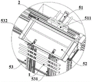
fig. 2 is a schematic view illustrating a state of cooperation between a first conveyor belt and a first docking unit of the spring strip blank conveying system according to the embodiment of the present invention;
fig. 3 is a schematic diagram illustrating the cooperation state of the second conveyor belt and the first docking unit of the spring strip blank conveying system according to the embodiment of the present invention;
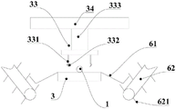
fig. 4 is a schematic diagram illustrating the cooperation state of the second conveyor belt and the second docking unit of the spring strip blank conveying system according to the embodiment of the present invention;
FIG. 5 is a schematic view of a first jaw of a spring bar blank transport system provided in accordance with an embodiment of the present invention;
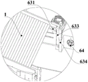
fig. 6 is a schematic diagram of a state of cooperation between a second scraper elevator and a feeding slope of the spring strip blank conveying system provided by the embodiment of the utility model;
FIG. 7 is a schematic illustration of a guide groove of a feed ramp of a spring blank transport system according to an embodiment of the present invention;
fig. 8 is a schematic view of a state of cooperation between a third conveyor belt and a second docking unit of the spring strip blank conveying system according to the embodiment of the present invention.
Detailed Description
To make the objects, technical solutions and advantages of the present invention more apparent, the technical solutions of the present invention are described below in detail and completely with reference to the accompanying drawings, and it is apparent that the described embodiments are some, but not all embodiments of the present invention. All other embodiments, which can be derived by a person skilled in the art from the embodiments given herein without making any creative effort, shall fall within the protection scope of the present invention.
As shown in fig. 1, this embodiment provides an elastic strip blank conveying system, including elastic strip blank 1 through first conveyer belt 2, second conveyer belt 3 and third conveyer belt 4 in proper order, first conveyer belt 2 and cutting equipment butt joint, first conveyer belt 2 shifts elastic strip blank 1 to second conveyer belt 3 through first butt joint unit 5 on, the second conveyer belt has at least one to the butt joint of third conveyer belt 4, the second conveyer belt is connected with third conveyer belt 4 through second butt joint unit 6, second conveyer belt 3 and the butt joint of thermoforming equipment.
This implementation is carried thermal forming equipment through the cooperation of a plurality of conveyer belts and butt joint unit with the bullet strip blank 1 of cutting in the cutting equipment, can guarantee the continuation of takt time, and second conveyer belt 3 can dock a plurality of third conveyer belts 4 simultaneously moreover to use a plurality of thermal forming equipment of cutting equipment butt joint, make cutting equipment can efficient work, improve production efficiency.
With reference to fig. 2, the first conveyor belt 2, the second conveyor belt 3, and the third conveyor belt 4 are respectively arranged in parallel, the elastic strip blank 1 can move on the first conveyor belt 2, the second conveyor belt 3, and the third conveyor belt 4 along the length direction, in this embodiment, a half of underground space is formed in a workshop by underground construction, the second conveyor belt 3 is disposed in the half of underground space, and the second conveyor belt 3 only transmits materials, so that the second conveyor belt 3 can be located below the ground when covering the support structure above the second conveyor belt 3, and other devices can be placed on the second conveyor belt 3 for passing through or placing on the second conveyor belt, and therefore, under the condition of increasing production equipment, the floor area does not need to be increased.
Referring to fig. 2, the first butting unit 5 includes a telescopic cylinder 51, a first material guiding plate 52 and a first scraper lifter 53, the telescopic cylinder 51 and the first material guiding plate 52 are respectively disposed on two sides of the first conveyor belt 2, one side of the first material guiding plate 52, which is away from the first conveyor belt 2, is inclined downward, the upper end of the stroke of the first scraper lifter 53 is butted with the discharging end of the first material guiding plate 52, and the output end of the telescopic cylinder 51 is fixedly connected with a first push plate 511.
The elastic strip blank 1 is conveyed to the discharge end on the first conveyor belt 2, then the telescopic cylinder 51 pushes the elastic strip blank 1 to the first material guide plate 52 through the first push plate 511, and under the action of motion inertia and gravity, the elastic strip blank 1 rolls on the first material guide plate 52 and enters the first scraper lifter 53, and moves downwards through the rotation of the first scraper lifter 53.
The first scraper elevator 53 comprises two parallel chains 531, the chains 531 are driven by sprockets to rotate in the vertical direction, a plurality of scrapers 532 are uniformly arranged on the chains 531 on two sides respectively, the included angle between each scraper 532 and the corresponding chain 531 in the direction opposite to the movement direction of the chain 531 is smaller than 90 degrees, the elastic strip blank 1 is placed on the inclined scrapers 532 to prevent rolling off, and after the scrapers 532 cross the uppermost ends of the chains 531, the elastic strip blank 1 rolls into the scrapers 532 and then rotates downwards along with the scrapers 532. Guide baffles 531 are arranged on two sides of the first material guide plate 52 to properly limit the axial position of the material guide plate 52 and ensure that the material guide plate can enter the first scraper lifter 53. Further, the upper end of the guide baffle 531 forms a first flange 522 toward the inside of the first guide plate 52 to prevent the spring strip blank 1 from jumping up on the first guide plate 52 due to collision or the like.
In order to be conveniently matched with the first scraper lifter 53, the lower end of the first material guide plate 52 is further provided with two first notched grooves 523, and the scrapers 532 on the chains 531 on the two sides can rotate to pass through the first notched grooves 531, so that the chains 531 can be tightly attached to the lower end of the first material guide plate 52, and the elastic strip blank 1 can conveniently roll into the scrapers 532.
Referring to fig. 3, the feeding end of the second conveyor belt 3 is provided with a clamping plate 31 with an upper end inclined to the outside on each side of the conveying direction, the clamping plate 31 on the side close to the first scraper lifter 53 is provided with two second notch grooves 32 for the scraper 532 to pass through, when the scraper 532 carries the elastic strip blank 1 to pass through the second notch grooves 32, the elastic strip blank 1 enters the clamping plate 31, and the scraper 532 leaves from the second notch grooves 32, thereby completing the process of transferring the elastic strip blank 1 from the first conveyor belt 2 to the second conveyor belt 3.
The second conveyer belt 3 drives the spring strip blank 1 to axially advance, and a plurality of groups of clamping plates 31 can be arranged on the conveying path of the second conveyer belt 3 as required to prevent the spring strip blank 1 from rolling off.
Referring to fig. 4, a first clamping jaw 33 is arranged above the output end of the second conveyor belt 3, the second docking unit includes a second material guide plate 61 and a second scraper lifter 62, the first clamping jaw 33 can clamp the elastic strip blank 1 on the second conveyor belt 3 and move above the second material guide plate 61, the second material guide plate 61 is fixed on the side surface of the second conveyor belt 3, the second material guide plate 61 is inclined downward and the end portion is tilted upward relative to the second conveyor belt 3, the end of the second material guide plate 61 away from the second conveyor belt 3 is arranged in a comb-shaped structure, the second scraper lifter 62 has a comb-shaped lifting plate 621, and the lifting plate 621 can pass through the comb-shaped structure of the second material guide plate 61; the first clamping jaw 33 clamps the elastic strip blank 1 and transversely moves to the second material guide plate 61 to be placed on the second material guide plate, then the elastic strip blank 1 is released, the elastic strip blank 1 automatically rolls to the outer side of the second material guide plate 61, the lifting plate 621 of the second scraper lifter 62 penetrates through the comb-shaped structure of the second material guide plate 61 to lift the elastic strip blank 1, and the elastic strip blank 1 is driven to move upwards along with the lifting plate 621.
In this embodiment, be provided with one respectively in the both sides of second conveyer belt 3 second butt joint unit 6, first clamping jaw 33 is fixed in on the direction of delivery vertically slide rail 34 with second conveyer belt 3, first clamping jaw 33 is alternative carries bullet strip blank 1 for the second butt joint unit 6 of both sides to take into account the collocation of different equipment takts. The first clamping jaw 33 comprises two clamping plates 331 which are parallel to each other, the opposite side surfaces of the clamping plates 331 are respectively provided with an inwards concave clamping groove 332, the two clamping plates 331 can be close to or far away from each other synchronously, and the two clamping plates 331 are driven by a lifting cylinder 333 to lift along the vertical direction.
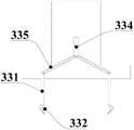
Specifically, two grip block 331 can be respectively the spiro union in the both ends of same lead screw, and the screw thread opposite direction at lead screw both ends, rotates through the motor drive lead screw and makes two grip block 331 simultaneous movement, perhaps refer to fig. 5, still be provided with two grip block 331 simultaneous movement of centre gripping cylinder drive on the first clamping jaw 33, specifically, the flexible end 334 of centre gripping cylinder is articulated to be connected with two connecting rods 335, two connecting rods 335 respectively with the articulated of a grip block 331 even, grip block 331 slides along the horizontal direction and sets up to under the pulling of connecting rod 335, can follow the horizontal direction and be close to or keep away from in step.
With reference to fig. 6, the second docking unit 6 further includes a feeding slope 63 docked with the upper end of the second scraper elevator 62, the elastic strip blank 1 moves to the upper end of the second scraper elevator 62 along with the second scraper elevator 62 and automatically enters the feeding slope 63, specifically, the feeding slope 63 includes two support plates 631 arranged in parallel, the side surfaces of the support plates 631 are further provided with baffle plates 632, the support plates 631 of the feeding slope 63 are arranged obliquely downward, after the elastic strip blank 1 is carried by the second scraper elevator 62 to move upward to the top end, the two ends of the elastic strip blank 1 enter the range of the two side support plates 631, the two ends of the elastic strip blank 1 are limited by the two side baffle plates 632, and automatically slide away from the lifting plates 632 under the support of the support plates 631.
Referring to fig. 7, the lower ends of the support plates 631 on both sides are connected to vertically downward guide grooves 633, the lower ends of the guide grooves 633 are horizontally provided with notches 634 allowing the elastic strip blank 1 to leave, the outer sides of the notches 634 are provided with chamfering machines 64 engaged with both ends of the elastic strip blank 1, a second push plate (not shown) is horizontally provided below the support plates 631, the second push plate is horizontally pushed out to push the elastic strip blank 1 on the lowest end out of the notches 634, the chamfering machines 64 perform chamfering processing on both ends of the elastic strip blank 1, at this time, the upper elastic strip blank 1 falls to the position of the notches 634, in order to prevent the elastic strip blank 1 from escaping from the notches 634, a protruding elastic piece (not shown) is provided at the notches 634, the distance between the notches 634 on both sides is controlled by the elastic pieces on both sides to prevent the elastic strip blank 1 from falling off, and at the same time, when the second push plate is pushed out, the elastic strip blank 1 is extruded by the two ends of the elastic strip blank 1 to deform and leave the notch 634, so that the elastic strip blank 1 can normally leave, and the elastic strip blank 1 automatically resets after passing through the elastic sheet to prevent the subsequent elastic strip blank 1 from automatically falling off.
Referring to fig. 8, a second clamping jaw (not shown) is further arranged above the chamfering machine 64, the structure of the second clamping jaw is the same as that of the first clamping jaw, a third material guide plate 65 is further arranged on the side face of the feed end of the third conveying belt 4, the second clamping jaw can transfer the elastic strip blank from the chamfering machine 64 to the third material guide plate 65, clamping plates are also arranged on two sides of the third conveying belt 4 so as to enable the elastic strip blank 1 to enter and limit, the lower end of the third material guide plate 65 guides the clamping plates, and the elastic strip blank 1 directly rolls from the third material guide plate 65 to fall into the range of the clamping plates on two sides, so that the elastic strip blank 1 can travel along with the third conveying belt 4.
The above examples are only intended to illustrate the technical solution of the present invention, but not to limit it; although the present invention has been described in detail with reference to the foregoing embodiments, it will be understood by those of ordinary skill in the art that: the technical solutions described in the foregoing embodiments may still be modified, or some technical features may be equivalently replaced; and such modifications or substitutions do not depart from the spirit and scope of the corresponding technical solutions of the embodiments of the present invention.
Claims (10)
1. A bullet strip blank conveying system which characterized in that: including first conveyer belt, second conveyer belt and the third conveyer belt that docks in proper order, first conveyer belt docks with cutting equipment, first conveyer belt passes through first butt joint unit and transports the second conveyer belt with bullet strip blank, the cooperation of second conveyer belt is docked at least one the third conveyer belt, the third conveyer belt passes through the second butt joint unit and is connected with the second conveyer belt, the second conveyer belt docks with the thermoforming equipment.
2. The spring blank transport system of claim 1, wherein: the first conveying belt, the second conveying belt and the third conveying belt are arranged in parallel, and the elastic strip blank moves on the first conveying belt, the second conveying belt and the third conveying belt along the length direction.
3. The spring blank transport system of claim 2, wherein: the second conveyer belt is arranged under the ground.
4. The spring blank transport system of claim 3, wherein: the first butt joint unit comprises a telescopic cylinder, a first guide plate and a first scraper lifter, the telescopic cylinder and the first guide plate are respectively arranged on two sides of the first conveying belt, one end, away from the first conveying belt, of the first guide plate inclines downwards, the upper end of the stroke of the first scraper lifter is in butt joint with the discharging end of the first guide plate, and the output end of the telescopic cylinder is fixedly connected with a first push plate.
5. The spring blank transport system of claim 4, wherein: the first scraper elevator comprises two parallel chains, the chains are driven by chain wheels to rotate approximately in the vertical direction, a plurality of scrapers are uniformly arranged on the chains on two sides respectively, and the elastic strip blank is placed on the scrapers to move downwards along with the chains.
6. The spring blank transport system of claim 5, wherein: the lower end of the first material guide plate is provided with two first notch grooves, and the scraping plates on the chains on two sides can rotate to pass through the first notch grooves;
the feed end of second conveyer belt is provided with the splint that the upper end leaned to the outside respectively in direction of delivery's both sides, is provided with two second breach grooves that supply the scraper blade to pass through on the splint that are close to first scraper blade lifting machine one side.
7. The spring blank transport system of claim 1, wherein: a first clamping jaw is arranged above the output end of the second conveying belt, the second butt joint unit comprises a second material guide plate and a second scraper lifter, and the first clamping jaw can clamp the elastic strip blank at the output end of the second conveying belt and move to the position above the second material guide plate; the second material guide plate is fixed on the side surface of the output end of the second conveying belt, the second material guide plate inclines downwards relative to the second conveying belt, the end part of the second material guide plate is upwarped, and one end, far away from the second conveying belt, of the second material guide plate is arranged to be of a comb-tooth-shaped structure; the second scraper lifter is provided with a comb-shaped lifting plate, and the lifting plate can pass through the comb-shaped structure of the second material guide plate.
8. The spring blank transport system of claim 7, wherein: the two sides of the output end of the second conveying belt are respectively provided with one second butt joint unit, the first clamping jaw is fixed on a sliding rail vertical to the conveying direction of the second conveying belt, the first clamping jaw comprises two clamping plates parallel to each other, the opposite side surfaces of the clamping plates are respectively provided with an inwards concave clamping groove, and the clamping plates can be synchronously close to or far away from each other.
9. The spring blank transport system of claim 7, wherein: the second butt joint unit further comprises a feeding slope in butt joint with the upper end of the second scraper lifter, the elastic strip blank moves to the upper end of the second scraper lifter along with the second scraper lifter and automatically enters the feeding slope, the feeding slope is arranged obliquely downwards, the lower end of the feeding slope is connected with a vertical downward guide groove, the lower end of the guide groove is provided with a notch allowing the elastic strip blank to leave, and the outer side of the notch is provided with a chamfering machine matched with the two ends of the elastic strip blank; the upper end of the chamfering machine is provided with a second clamping jaw, a third material guide plate is obliquely arranged on the side face of the feeding end of the third conveying belt, the second clamping jaw moves the elastic strip blank to the third material guide plate from the chamfering machine, and the elastic strip blank can enter the third conveying belt by rolling along the third material guide plate.
10. The system of claim 9, wherein: the notch at the lower end of the guide groove is provided with a protruding elastic sheet, and one side of the notch, which is far away from the chamfering machine, is provided with a second push plate which pushes the elastic strip blank out of the chamfering machine.
Priority Applications (1)
| Application Number | Priority Date | Filing Date | Title |
|---|---|---|---|
| CN202123235995.4U CN216540582U (en) | 2021-12-20 | 2021-12-20 | Elastic strip blank conveying system |
Applications Claiming Priority (1)
| Application Number | Priority Date | Filing Date | Title |
|---|---|---|---|
| CN202123235995.4U CN216540582U (en) | 2021-12-20 | 2021-12-20 | Elastic strip blank conveying system |
Publications (1)
| Publication Number | Publication Date |
|---|---|
| CN216540582U true CN216540582U (en) | 2022-05-17 |
Family
ID=81545631
Family Applications (1)
| Application Number | Title | Priority Date | Filing Date |
|---|---|---|---|
| CN202123235995.4U Active CN216540582U (en) | 2021-12-20 | 2021-12-20 | Elastic strip blank conveying system |
Country Status (1)
| Country | Link |
|---|---|
| CN (1) | CN216540582U (en) |
-
2021
- 2021-12-20 CN CN202123235995.4U patent/CN216540582U/en active Active
Similar Documents
| Publication | Publication Date | Title |
|---|---|---|
| CN204354239U (en) | Full-automatic high frequency plate joggling apparatus | |
| CN107877006A (en) | A kind of all automatic numerical control laser pipe cutting machine | |
| CN213356014U (en) | Deviation rectifying and aligning equipment for corrugated case | |
| GB2061893A (en) | Pipe feeding apparatus | |
| CN105108357B (en) | Automatic loading device used for pipe cutter | |
| KR101569802B1 (en) | Pipe transfer apparatus | |
| CN112871698B (en) | Flexible intelligent sorting line and sorting method for woodworking industry | |
| CN109351525B (en) | Automatic paint spraying machine | |
| EP2106377B1 (en) | Apparatus for separating plate-shaped objects | |
| CN105819232A (en) | Automatic stacking device and stacking method thereof | |
| CN216540582U (en) | Elastic strip blank conveying system | |
| CN214526570U (en) | Steel pipe transfer device in cutting chamfer production line | |
| CN204893227U (en) | Be used for pipe cutting machine automatic feeding device | |
| CN113977241A (en) | Automatic assembling system of fixed joint assembly | |
| CN110326653B (en) | Meat product processing system | |
| CN114178422A (en) | Elastic strip blank conveying system | |
| CN107900539A (en) | A kind of all automatic numerical control laser pipe cutting machine conveying system | |
| CN112623777A (en) | Turnover basket conveying system, wood board basket loading system and basket loading method | |
| CN112660830B (en) | Wood board sorting bin, system and method | |
| CN115744225A (en) | Automatic plug machine of beating of tubular product | |
| CN205634205U (en) | Automatic stacking device | |
| CN212449944U (en) | Aluminum substrate layered storage system | |
| CN214059068U (en) | Plank conveying system | |
| CN114314001A (en) | Glass insert equipment | |
| CN209870902U (en) | Section bar bagging equipment |
Legal Events
| Date | Code | Title | Description |
|---|---|---|---|
| GR01 | Patent grant | ||
| GR01 | Patent grant |