CN215081041U - Rehabilitation seat and wheelchair - Google Patents
Rehabilitation seat and wheelchair Download PDFInfo
- Publication number
- CN215081041U CN215081041U CN202120883319.9U CN202120883319U CN215081041U CN 215081041 U CN215081041 U CN 215081041U CN 202120883319 U CN202120883319 U CN 202120883319U CN 215081041 U CN215081041 U CN 215081041U
- Authority
- CN
- China
- Prior art keywords
- push rod
- rehabilitation
- seat
- leg
- guide
- Prior art date
- Legal status (The legal status is an assumption and is not a legal conclusion. Google has not performed a legal analysis and makes no representation as to the accuracy of the status listed.)
- Active
Links
Images


Landscapes
- Rehabilitation Tools (AREA)
Abstract
A chair for rehabilitation relates to the technical field of rehabilitation equipment, comprising: the chair seat structure comprises a cushion and a chair back arranged on one side of the cushion; the leg supporting plate is hinged to the other side, opposite to the seat back, of the seat cushion; the leg rehabilitation structure is arranged on the chair seat structure and comprises a push rod structure and a first motor, the push rod structure can move relative to the chair seat structure, and the first motor is used for driving the push rod structure to move; one side of the push rod structure is in contact with the inner side surface of the leg supporting plate. The utility model discloses a seat is moved by motor drive user's shank to realize the effect of rehabilitating, the utility model discloses area is little when the small and exquisite use of structure, can regard as the complementary unit of most wheelchair now even, makes the user sit and can accomplish the sports of rehabilitating on the wheelchair, need not consume a large amount of physical power equipment of rehabilitating from top to bottom.
Description
Technical Field
The utility model relates to a rehabilitation equipment technical field especially relates to a chair and wheelchair of having a good luck again.
Background
After structural or functional damage occurs to a human body, particularly to limbs, muscles and bones with motor functions, exercise rehabilitation therapy means which aims to recover the functions of healthy limbs or partial functions by various methods and apparatuses in a progressive manner is rehabilitation manner. Nowadays, with the continuous improvement of medical systems, more and more products aiming at rehabilitation appear. For example, chinese utility model patent with publication number CN 212522353U discloses a nerve-usable leg rehabilitation device, which comprises a leg rehabilitation device base, wherein one end of the leg rehabilitation device base is provided with a support frame, the support frame is embedded into the leg rehabilitation device base, one end of the support frame is provided with a foot placing plate, the upper surface of the other end of the leg rehabilitation device base is provided with a hydraulic column, the center of the hydraulic column is provided with a connecting shaft, and the end of the connecting shaft is provided with a treading rod; through the junction design hydraulic column at seat and shank are strong again device base, avoid current department of neurology to lead to the position of sitting not right with shank is strong device using because everybody's height is different, make the health uncomfortable, can not rise the use to the seat, can not reach everybody balance's comfortable position of sitting, can step on the pole through the pedal, make the connecting axle make the hydraulic column constantly rise or reduce at the inside continuous motion of hydraulic column, use according to individual at any time and adjust comfortable height.
However, the inventor of the present application finds that the above technical solutions have at least the following technical problems:
the whole heavier and area of structure is big, is similar to body-building apparatus, and the shank is passive exercise, and more is the arm and the waist abdomen strength of taking exercise the user, and the pertinence is relatively poor and physical power loss is great to the user, takes exercise inefficiency.
SUMMERY OF THE UTILITY MODEL
Problem to exist among the prior art, the utility model provides a rehabilitation seat and wheelchair, the utility model discloses a seat is moved by motor drive user's shank to realize the effect of rehabilitating, the utility model discloses area is little when the small and exquisite use of structure can regard as the complementary unit of most wheelchair now even, makes the user sit and can accomplish the exercise of rehabilitating on the wheelchair, need not consume a large amount of physical power equipment of rehabilitating from top to bottom.
A rehabilitation chair comprising: the chair seat structure comprises a cushion and a chair back arranged on one side of the cushion; the leg supporting plate is hinged to the other side, opposite to the seat back, of the seat cushion; the leg rehabilitation structure is arranged on the chair seat structure and comprises a push rod structure and a first motor, the push rod structure can move relative to the chair seat structure, and the first motor is used for driving the push rod structure to move; one side of the push rod structure is contacted with the inner side surface of the leg supporting plate to realize the movement of the leg supporting plate.
Preferably, the top end of the push rod structure is provided with a plurality of guide wheels which are arranged in parallel, and each guide wheel is in rolling contact with the inner side surface of the leg supporting plate.
Preferably, the inner side surface of the leg supporting plate is provided with a plurality of parallel guide channels; the guide way is matched with the number of the guide wheels, is a linear track and is used for providing accurate guide for the guide wheels.
Preferably, the push rod structure comprises a first-stage push rod and a second-stage push rod, wherein the second-stage push rod is at least partially arranged in the first-stage push rod and can move relative to the first-stage push rod; one end of the second-stage push rod is arranged in the first-stage push rod, the other end of the second-stage push rod is in contact with the inner side face of the leg supporting plate, and the second-stage push rod is locked at the position opposite to the first-stage push rod by a locking structure.
Preferably, the locking structure includes a limiting member and a plurality of limiting holes for matching with the limiting member; the plurality of limiting holes are formed in the secondary push rod; the limiting piece is movably arranged in the first-stage push rod; the top end profile of the limiting piece is matched with the profile of the limiting hole.
Preferably, as for the above technical solution, the push rod structure is at least partially disposed inside the seat structure, and is driven by the first motor to perform telescopic motion in a direction of the seat structure toward the side of the leg rest.
Preferably, the first motor is fixedly arranged on the lower end surface of the seat structure, a power mechanism accommodating groove used for driving and connecting the first motor and the push rod structure is further formed in the lower end surface of the seat structure, and the gear structure of the first motor is meshed with the rack structure of the push rod structure through the power mechanism accommodating groove.
Preferably, the primary push rod includes at least two guide sleeve structures, the secondary push rod includes at least two guide pillar structures, the number of the guide sleeve structures is equal to that of the guide pillar structures, and the secondary push rod is in sliding connection with the guide sleeve structures of the primary push rod in a matched manner through the guide pillar structures.
Preferably, the leg support plate is arranged at the lower end of the leg support plate and is vertically connected with the leg support plate.
A wheelchair comprises the rehabilitation seat in any technical scheme, and the rehabilitation seat is connected with a driving structure of the wheelchair through a wheelchair connecting structure.
To sum up, the utility model has the advantages of it is following:
1. the utility model is mainly used for rehabilitation of the legs of a user, the electric structure is adopted to drive the legs of the user to move in the embodiment of the application, the physical strength of the user is saved, the electric structure and the rehabilitation chair are small and small in size and small in occupied area, and even the rehabilitation chair can be replaced into a chair seat of a conventional wheelchair, so that the user can finish rehabilitation of the legs on the wheelchair;
2. furthermore, the initial swing angle of the leg supporting plate can be automatically controlled in the embodiment of the application, and the push rod structure is provided with a perfect guide system, so that the swing of the leg supporting plate is more stable, and the discomfort caused by the swing of the leg supporting plate when a user uses the leg supporting plate is avoided;
3. the chair seat structure in this application embodiment not only is applicable to wounded and sick personnel and carries out the shank and rehabilitate, and push rod structure also can play the supporting role and make the leg layer board rotate certain angle for the chair seat structure and make the chair of rehabilitating also can regard as lazy people's seat to install on furniture such as sofa.
Drawings
FIG. 1 is a schematic view of a seat structure according to an embodiment of the present application;
FIG. 2 is a schematic view of a leg support plate and a leg rehabilitation structure according to an embodiment of the present application;
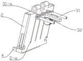
fig. 3 is a schematic view of a leg rehabilitation structure according to an embodiment of the present application;
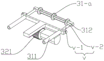
fig. 4 is an exploded view of a leg rehabilitation structure according to an embodiment of the present application;
FIG. 5 is a schematic structural view of a wheelchair in accordance with an embodiment of the present application;
the wheelchair comprises a seat structure 1, a leg supporting plate 2, a leg rehabilitation structure 3, a leg supporting plate 4, a wheelchair connecting structure 5, a cushion 11, a chair back 12, a push rod 31, a first motor 32, a first-stage push rod 311, a second-stage push rod 312, a rack 313, a gear 321, a guide sleeve 3111, a guide pillar 3121, a connecting column 3122, a v-locking structure, a v-1-limiting part, a v-2-limiting hole, a guide way 2-a and a guide wheel 31-a.
Detailed Description
The terms of orientation of up, down, left, right, front, back, top, bottom, and the like as referred to or as may be referred to in this specification are defined with respect to the configuration shown in the drawings, and the terms "inner" and "outer" refer to directions toward and away from the geometric center of a particular component and are relative terms, and thus may be changed accordingly depending on the position and the state of use of the particular component. Therefore, these and other directional terms should not be construed as limiting terms.
The invention is further explained below with reference to the following examples:
example (b):
a wheelchair for rehabilitation is structurally shown in figure 5, a seat of the wheelchair is a rehabilitation seat, as shown in figure 1, a rehabilitation seat comprises a seat structure 1, leg supporting plates 2, a leg rehabilitation structure 3 and foot supporting plates 4, the seat structure 1 consists of a seat cushion 11 and a seat back 12, the leg supporting plates 2 and the seat back 12 are respectively arranged on the front side and the rear side of the seat cushion 11, the leg supporting plates 2 are hinged with the seat cushion 11, and the leg rehabilitation structure 3 controls the leg supporting plates 2 to rotate relative to the seat cushion 11. The rehabilitation chair is connected to the wheelchair for rehabilitation through a wheelchair connecting structure 5.
Referring to fig. 2, referring to fig. 1, the leg rehabilitation structure 3 includes a first motor 32 and a push rod structure 31, and the seat cushion 11 is provided therein with an accommodating cavity for accommodating the push rod structure 31; the accommodating cavity is provided with two openings, one opening is an inlet and outlet groove facing the side surface of the leg supporting plate 2 and used for the push rod structure 31 to enter and exit the cushion 11, the other opening is a power mechanism accommodating groove inwards formed in the lower end surface of the cushion 11, and the power mechanism accommodating groove is communicated with the inlet and outlet groove; referring to fig. 2, fig. 3 and fig. 4, the push rod structure 31 includes a first-stage push rod 311, a second-stage push rod 312 and a rack structure 313, wherein the second-stage push rod 312 is telescopically disposed in the first-stage push rod 311, and the rack structure 313 is fixedly disposed on a lower end surface of the first-stage push rod 311. The first motor 32 is fixedly disposed on the lower end surface of the seat cushion 11, the first motor 32 drives a gear structure 321 to rotate, the lower end surface of the push rod structure 31 is a rack structure 313, and the gear structure 321 is engaged with the rack structure 313 through a power structure accommodating groove to control the whole push rod structure 31 to perform linear reciprocating motion.
The secondary push rod 312 comprises two guide post structures 3121, the primary push rod 311 comprises two guide sleeve structures 3111, the two guide post structures 3121 for accommodating the secondary push rod 312 are arranged inside the guide sleeve structures 3111, so that the secondary push rod 312 is movably arranged inside the primary push rod 311, and the two or more guide post structures 3121 are matched with the guide sleeve structures 3111, so that the secondary push rod 312 is more stable inside the primary push rod 311 and is not easy to shake; the secondary push rod 312 is locked at a relative position with the primary push rod 311 by a locking structure v, the locking structure v comprises a limiting piece v-1 and three limiting holes v-2 for matching with the limiting piece v-1, the number of the locking structures v is two, and the two locking structures v are respectively arranged on two sets of guide pillar and guide sleeve structures, the one set of guide pillar and guide sleeve structures refer to a guide pillar structure 3121 and a guide sleeve structure 3111 which are matched, the three limiting holes v-2 are uniformly arranged on the guide pillar structure 3121, the limiting piece v-1 is arranged in the guide sleeve structure 3111 and can move longitudinally in the guide sleeve structure 3111, but the longitudinal movement range of the limiting piece v-1 is limited, the limiting piece v-1 moves in a containing area which is arranged in the guide sleeve structure 3111 and is used for containing the limiting piece v-1, and a reset spring is further arranged in the containing area; when the operation is performed, a user firstly pulls the limiting piece v-1, the limiting piece v-1 is longitudinally far away from the limiting hole v-2, the locking position between the first-stage push rod 311 and the second-stage push rod 312 is opened (the return spring is compressed at the moment), the second-stage push rod 312 can move in the first-stage push rod 311, when the second-stage push rod 312 is adjusted to the length required to extend out (the extending length needs the limiting piece v-1 to retract, the limiting piece can just enter one limiting hole v-2), the user loosens the limiting piece v-1, and enters the limiting hole v-2 under the action of elastic potential energy, so that the limiting of the second-stage push rod 312 under the extending length is completed. The push rod structure 31 is a telescopic structure, and because the legs of the user can not be naturally bent by 90 degrees due to injury, the push rod structure 31 enables the user to set the initial bending degree of the legs according to the requirement in the setting mode; because in this embodiment, the leg supporting plate 2 is mainly used for supporting the leg of the user, under the pushing of the pushing rod structure 31, the leg supporting plate 2 can be turned upwards, and once the pushing rod structure 31 is retracted, the leg supporting plate 2 can also be turned downwards under the action of the gravity of the leg of the implementer to recover to the original position, so that the leg supporting plate 2 can be continuously rotated within a certain angle due to the reciprocating motion, thereby driving the leg of the user to repeatedly move between knee bending and lying, and realizing the leg rehabilitation of the user.
Referring to fig. 2 again, with reference to fig. 4, since the top end of the push rod structure 31 directly contacts the leg support plate 2, the leg support plate 2 can be lifted by using a spherical top end surface, so that the inner side surface of the leg support plate 2 is not scratched, but the support performance and the guide performance are poor, in this embodiment, the top end of the push rod structure 31 is provided with three parallel guide wheels 31-a, the three guide wheels 31-a are arranged between two guide pillar structures 3121, the top ends of the two guide pillar structures 3121 are connected by a connecting column 3122, so that the whole secondary push rod 312 is in a "U" shape structure, and the three guide wheels 31-a are rotatably arranged on the connecting column 3122; three parallel guide ways 2-a are arranged on the inner side surface of the leg supporting plate 2, and the guide ways 2-a are linear tracks; the three guide ways 2-a are used for accommodating the three guide wheels 31-a, the existence of the guide wheels 31-a enables the push rod structure 31 to have accurate direction when pushing the leg supporting plate 2, and the guide ways 2-a on the leg supporting plate 2 are matched to further limit the moving track of the guide wheels 31-a, so that the leg supporting plate 2 can swing more stably relative to the seat structure 1.
While the preferred embodiments of the present invention have been described, additional variations and modifications in those embodiments may occur to those skilled in the art once they learn of the basic inventive concepts. It is therefore intended that the appended claims be interpreted as including the preferred embodiment and all such alterations and modifications as fall within the scope of the invention.
It will be apparent to those skilled in the art that various changes and modifications may be made without departing from the spirit and scope of the invention. Thus, if such modifications and variations of the present invention fall within the scope of the claims and their equivalents, the present invention is also intended to include such modifications and variations.
Claims (10)
1. A chair for rehabilitation is characterized by comprising:
the chair seat structure (1) comprises a cushion (11) and a chair back (12) arranged on one side of the cushion (11);
the leg supporting plate (2) is hinged to the other side, opposite to the seat back (12), of the seat cushion (11);
the leg rehabilitation structure (3) is arranged on the chair seat structure (1), the leg rehabilitation structure (3) comprises a push rod structure (31) and a first motor (32), the push rod structure (31) can move relative to the chair seat structure (1), and the first motor (32) is used for driving the push rod structure (31) to move; one side of the push rod structure (31) is in contact with the inner side surface of the leg supporting plate (2) to realize the movement of the leg supporting plate (2).
2. A rehabilitation seat according to claim 1, characterized in that: the top end of the push rod structure (31) is provided with a plurality of guide wheels (31-a) which are arranged in parallel, and each guide wheel (31-a) is in rolling contact with the inner side surface of the leg supporting plate (2).
3. A rehabilitation seat according to claim 2, wherein: a plurality of parallel guide ways (2-a) are arranged on the inner side surface of the leg supporting plate (2); the guide way (2-a) is adapted to the number of guide wheels (31-a), and the guide way (2-a) is a linear track, and the guide way (2-a) is used for providing accurate guide for the guide wheels (31-a).
4. A rehabilitation seat according to claim 1, characterized in that: the push rod structure (31) comprises a primary push rod (311) and a secondary push rod (312), wherein the secondary push rod (312) is at least partially arranged in the primary push rod (311), and the secondary push rod (312) can move relative to the primary push rod (311); one end of the secondary push rod (312) is arranged inside the primary push rod (311), the other end of the secondary push rod is in contact with the inner side face of the leg supporting plate (2), and the relative position of the secondary push rod (312) and the primary push rod (311) is locked by a locking structure (v).
5. A rehabilitation seat according to claim 4, wherein: the locking structure (v) comprises a limiting piece (v-1) and a plurality of limiting holes (v-2) matched with the limiting piece (v-1); the limiting holes (v-2) are formed in the secondary push rod (312); the limiting piece (v-1) is movably arranged in the primary push rod (311); the top end profile of the limiting piece (v-1) is matched with the profile of the limiting hole (v-2).
6. A rehabilitation seat according to claim 1, characterized in that: the push rod structure (31) is at least partially arranged inside the seat structure (1) and is driven by the first motor (32) to do telescopic motion on the side face direction of the seat structure (1) facing the leg supporting plate (2).
7. A rehabilitation seat according to claim 6, wherein: the first motor (32) is fixedly arranged on the lower end face of the seat structure (1), a power mechanism accommodating groove used for driving and connecting the first motor (32) and the push rod structure (31) is further formed in the lower end face of the seat structure (1), and a gear structure (321) of the first motor (32) is meshed with a rack structure (313) of the push rod structure (31) through the power mechanism accommodating groove.
8. A rehabilitation seat according to claim 4, wherein: the primary push rod (311) comprises at least two guide sleeve structures (3111), the secondary push rod (312) comprises at least two guide pillar structures (3121), the number of the guide sleeve structures (3111) is equal to that of the guide pillar structures (3121), and the secondary push rod (312) is in sliding connection with the guide sleeve structures (3111) of the primary push rod (311) through the guide pillar structures (3121).
9. A rehabilitation seat according to claim 1, characterized in that: the leg support plate is characterized by further comprising a leg support plate (4), wherein the leg support plate (4) is arranged at the lower end of the leg support plate (2), and the leg support plate (4) is vertically connected with the leg support plate (2).
10. A wheelchair, comprising a rehabilitation chair according to any of claims 1-9, said rehabilitation chair being connected to a drive structure of the wheelchair via a wheelchair connection (5).
Priority Applications (1)
| Application Number | Priority Date | Filing Date | Title |
|---|---|---|---|
| CN202120883319.9U CN215081041U (en) | 2021-04-27 | 2021-04-27 | Rehabilitation seat and wheelchair |
Applications Claiming Priority (1)
| Application Number | Priority Date | Filing Date | Title |
|---|---|---|---|
| CN202120883319.9U CN215081041U (en) | 2021-04-27 | 2021-04-27 | Rehabilitation seat and wheelchair |
Publications (1)
| Publication Number | Publication Date |
|---|---|
| CN215081041U true CN215081041U (en) | 2021-12-10 |
Family
ID=79272383
Family Applications (1)
| Application Number | Title | Priority Date | Filing Date |
|---|---|---|---|
| CN202120883319.9U Active CN215081041U (en) | 2021-04-27 | 2021-04-27 | Rehabilitation seat and wheelchair |
Country Status (1)
| Country | Link |
|---|---|
| CN (1) | CN215081041U (en) |
-
2021
- 2021-04-27 CN CN202120883319.9U patent/CN215081041U/en active Active
Similar Documents
| Publication | Publication Date | Title |
|---|---|---|
| CN102688124B (en) | Linked-control electric reclining wheelchair | |
| CN109730897B (en) | Leg injury rehabilitation training device | |
| CN109984892A (en) | Tip-up seat in multifunctional room | |
| CN101357098A (en) | Sport body-building massage chair | |
| CN213250507U (en) | Wheelchair with leg exercise function | |
| CN108703860A (en) | A kind of postpartum bone Pelvic floor rehabilitation material | |
| CN108771607A (en) | A kind of postpartum pelvis bottom muscle repairs training device | |
| KR101441290B1 (en) | Muscular exercise and massage chair | |
| CN201076207Y (en) | Sports fitness massage chair | |
| CN214512510U (en) | Old person takes exercise equipment with shank | |
| CN215081041U (en) | Rehabilitation seat and wheelchair | |
| CN108786017A (en) | A kind of bone Pelvic floor recovering aid equipment | |
| CN108714091A (en) | A kind of postpartum bone Pelvic floor reparation equipment | |
| CN211461063U (en) | Active and passive lower limb training device | |
| CN112754788B (en) | Rehabilitation wheelchair | |
| CN111568696B (en) | Hip movement device for hemiplegic patient | |
| CN210205744U (en) | Bicycle rehabilitation training device | |
| CN208260066U (en) | A kind of mobile device for healing and training of medical treatment and nursing | |
| KR20140052148A (en) | Sit-up bench | |
| CN113995631A (en) | Sitting type four-limb rehabilitation training equipment | |
| CN113576841A (en) | Device is assisted to kneeling to cushion of hemiplegia patient | |
| CN220478048U (en) | Linkage type lower limb muscle strength training device | |
| CN215609118U (en) | Weight-bearing backrest type squatting and rising device | |
| CN219090044U (en) | Training device for lower limb rehabilitation | |
| CN114733149B (en) | Sliding bed for lower limb muscle strength training |
Legal Events
| Date | Code | Title | Description |
|---|---|---|---|
| GR01 | Patent grant | ||
| GR01 | Patent grant |