CN211182181U - Chip packaging structure of wave filter assembly - Google Patents
Chip packaging structure of wave filter assembly Download PDFInfo
- Publication number
- CN211182181U CN211182181U CN202020253346.3U CN202020253346U CN211182181U CN 211182181 U CN211182181 U CN 211182181U CN 202020253346 U CN202020253346 U CN 202020253346U CN 211182181 U CN211182181 U CN 211182181U
- Authority
- CN
- China
- Prior art keywords
- chip
- heat absorption
- box
- wave filter
- packaging box
- Prior art date
- Legal status (The legal status is an assumption and is not a legal conclusion. Google has not performed a legal analysis and makes no representation as to the accuracy of the status listed.)
- Expired - Fee Related
Links
Images

Abstract
The utility model discloses a wave filter subassembly's chip package structure, including the encapsulation box, the clamp plate is installed on the top of encapsulation box, the pin is installed to the both sides of encapsulation box, the radiating seat is installed to the bottom of encapsulation box, be provided with the louvre on the radiating seat, the internally mounted of encapsulation box has the support, the heat absorption backing plate is installed at the top of support, the chip is installed at the top of heat absorption backing plate, the conducting strip is installed to the bottom of heat absorption backing plate. The utility model discloses a clamp plate is installed on the top of packaging box, seals fixedly through the clamp plate convenience to packaging box's top, and has the support at packaging box's internally mounted, installs the heat absorption backing plate at the top of support, through its installation that makes things convenient for the chip, the conducting strip is installed to the bottom of heat absorption backing plate, and installs the radiating seat in packaging box's bottom, is provided with the louvre on the radiating seat, can improve the radiating effect to the chip through this kind of design.
Description
Technical Field
The utility model relates to a chip package structure technical field specifically is a chip package structure of wave filter subassembly.
Background
A chip package structure of wave filter component is used to package the chip of wave filter component, the power filter is a filter circuit composed of capacitor, inductor and resistor, the filter can effectively filter the frequency point of specific frequency in the power line or the frequency beyond the frequency point to obtain a power signal of specific frequency, or eliminate a power signal after specific frequency, the shell for installing semiconductor integrated circuit chip plays the role of placing, fixing, sealing, protecting chip and enhancing electric heating performance, and is also a bridge for communicating the chip internal world with the external circuit, the connection point on the chip is connected to the pins of the package shell by wires, these pins are connected with other devices by wires on the printed board, therefore, the package plays an important role to CPU and other L SI integrated circuits.
The chip packaging structure of the wave filter assembly at the present stage has many disadvantages, for example, the installation and the disassembly are inconvenient, the replacement of the chip is inconvenient, and the heat dissipation performance is poor.
SUMMERY OF THE UTILITY MODEL
An object of the utility model is to provide a chip package structure of wave filter subassembly to the installation that proposes in solving above-mentioned background art is dismantled inconveniently, and the change of chip is inconvenient, and the poor scheduling problem of heat dispersion.
In order to achieve the above object, the utility model provides a following technical scheme: the utility model provides a wave filter subassembly's chip package structure, includes the encapsulation box, the clamp plate is installed on the top of encapsulation box, the pin is installed to the both sides of encapsulation box, the radiating seat is installed to the bottom of encapsulation box, be provided with the louvre on the radiating seat, the internally mounted of encapsulation box has the support, the heat absorption backing plate is installed at the top of support, the chip is installed at the top of heat absorption backing plate, the conducting strip is installed to the bottom of heat absorption backing plate.
Preferably, one end of the pin is provided with a raised head, and the pin is connected with two sides of the packaging box in an embedded manner through the raised head.
Preferably, the bottom of the heat conducting fin is arranged on the inner side of the heat radiating seat, and the heat radiating fan structure is arranged on the inner side of the heat radiating seat.
Preferably, the inner side of the heat absorption base plate is provided with a groove, and the chip is connected with the groove in the heat absorption base plate in an embedded manner.
Preferably, the pressure plate is mounted on the top of the packaging box through bolts, and the packaging box is of a plastic structure.
Preferably, the pins are provided with ten pins, and the ten pins are respectively installed at two ends of the packaging box.
Compared with the prior art, the beneficial effects of the utility model are that:
1. the top end of the packaging box of the utility model is provided with the pressing plate, the top of the packaging box is conveniently sealed and fixed through the pressing plate, the inside of the packaging box is provided with the support, the top of the support is provided with the heat absorption backing plate, and the chip is conveniently installed through the heat absorption backing plate;
2. the utility model discloses a conducting strip is installed to the bottom of heat absorption backing plate, and installs the radiating seat in the bottom of encapsulation box, is provided with the louvre on the radiating seat, can improve the radiating effect to the chip through this kind of design.
Drawings
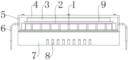
Fig. 1 is a schematic structural diagram of a chip package structure of a wave filter assembly according to the present invention;
FIG. 2 is a front view of the present invention;
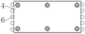
fig. 3 is a top view of the pressing plate of the present invention.
In the figure: 1. a heat conductive sheet; 2. a support; 3. a chip; 4. pressing a plate; 5. packaging the box; 6. a pin; 7. a heat dissipation base; 8. heat dissipation holes; 9. a heat sink pad.
Detailed Description
The technical solutions in the embodiments of the present invention will be described clearly and completely with reference to the accompanying drawings in the embodiments of the present invention, and it is obvious that the described embodiments are only some embodiments of the present invention, not all embodiments.
Referring to fig. 1-3, the present invention provides an embodiment: the utility model provides a wave filter subassembly's chip package structure, including packaging box 5, clamp plate 4 is installed on packaging box 5's top, clamp plate 4 is used for protecting packaging box 5's top, pin 6 is installed to packaging box 5's both sides, pin 6 makes things convenient for external equipment, packaging box 5's bottom is installed heat dissipation seat 7, heat dissipation seat 7 is used for dispelling the heat to packaging box 5 through louvre 8, be provided with louvre 8 on the heat dissipation seat 7, packaging box 5's internally mounted has support 2, support 2 is convenient fixed to the installation of chip, heat absorption backing plate 9 is installed at support 2's top, heat absorption backing plate 9 is used for absorbing chip 3, chip 3 is installed at heat absorption backing plate 9's top, conducting strip 1 is installed to heat absorption backing plate 9's bottom, conducting strip 1 is used for with the leading-in heat radiating seat 7, the convenient.
Furthermore, one end of the pin 6 is provided with a raised head, the pin 6 is connected with two sides of the packaging box 5 in an embedded mode through the raised head, and the pin 6 is convenient to mount and fix through the raised head.
Further, the bottom of the heat conducting fin 1 is installed on the inner side of the heat radiating seat 7, and the heat radiating fan structure is installed on the inner side of the heat radiating seat 7, so that the heat radiating effect of the packaging structure is improved through the heat radiating seat 7.
Further, the inner side of the heat absorption backing plate 9 is provided with a groove, the chip 3 is connected with the groove in the heat absorption backing plate 9 in an embedded mode, and the chip 3 is convenient to install on the top of the heat absorption backing plate 9 through the groove.
Further, the pressing plate 4 is installed at the top of the packaging box 5 through bolts, the packaging box 5 is of a plastic structure, and the top of the packaging box 5 is protected conveniently through the pressing plate 4.
Further, ten pins 6 are provided, and the ten pins 6 are respectively installed at both ends of the package box 5.
The working principle is as follows: this equipment is when using, install the chip on the heat absorption backing plate 9 at the top of support 2, then pass through the bolt with clamp plate 4 and install the top at encapsulation box 5, install pin 6 in the both sides of encapsulation box 5 through the plug of its one end, absorb the heat through heat absorption backing plate 9, and through conducting strip 1 with heat transfer to radiating seat 7 in, dispel the heat through louvre 8 on the radiating seat 7, improve packaging structure's radiating effect, be used for external equipment through pin 6, make external equipment be connected with chip 3.
It is obvious to a person skilled in the art that the invention is not restricted to details of the above-described exemplary embodiments, but that it can be implemented in other specific forms without departing from the spirit or essential characteristics of the invention. The present embodiments are therefore to be considered in all respects as illustrative and not restrictive, the scope of the invention being indicated by the appended claims rather than by the foregoing description, and all changes which come within the meaning and range of equivalency of the claims are therefore intended to be embraced therein. Any reference sign in a claim should not be construed as limiting the claim concerned.
Claims (6)
1. A chip packaging structure of a wave filter assembly, comprising a packaging box (5), characterized in that: pressing plate (4) are installed on the top of encapsulation box (5), pin (6) are installed to the both sides of encapsulation box (5), radiating seat (7) are installed to the bottom of encapsulation box (5), be provided with louvre (8) on radiating seat (7), the internally mounted of encapsulation box (5) has support (2), heat absorption backing plate (9) are installed at the top of support (2), chip (3) are installed at the top of heat absorption backing plate (9), conducting strip (1) is installed to the bottom of heat absorption backing plate (9).
2. The chip package structure of a wave filter assembly according to claim 1, characterized in that: one end of the pin (6) is provided with a raised head, and the pin (6) is connected with two sides of the packaging box (5) in an embedded mode through the raised head.
3. The chip package structure of a wave filter assembly according to claim 1, characterized in that: the bottom of the heat conducting fin (1) is arranged on the inner side of the heat radiating seat (7), and the inner side of the heat radiating seat (7) is provided with a heat radiating fan structure.
4. The chip package structure of a wave filter assembly according to claim 1, characterized in that: the inner side of the heat absorption base plate (9) is provided with a groove, and the chip (3) is connected with the groove in the heat absorption base plate (9) in an embedded manner.
5. The chip package structure of a wave filter assembly according to claim 1, characterized in that: the pressing plate (4) is installed at the top of the packaging box (5) through bolts, and the packaging box (5) is of a plastic structure.
6. The chip package structure of a wave filter assembly according to claim 1, characterized in that: the pins (6) are ten in number, and the ten pins (6) are respectively arranged at two ends of the packaging box (5).
Priority Applications (1)
| Application Number | Priority Date | Filing Date | Title |
|---|---|---|---|
| CN202020253346.3U CN211182181U (en) | 2020-03-04 | 2020-03-04 | Chip packaging structure of wave filter assembly |
Applications Claiming Priority (1)
| Application Number | Priority Date | Filing Date | Title |
|---|---|---|---|
| CN202020253346.3U CN211182181U (en) | 2020-03-04 | 2020-03-04 | Chip packaging structure of wave filter assembly |
Publications (1)
| Publication Number | Publication Date |
|---|---|
| CN211182181U true CN211182181U (en) | 2020-08-04 |
Family
ID=71808969
Family Applications (1)
| Application Number | Title | Priority Date | Filing Date |
|---|---|---|---|
| CN202020253346.3U Expired - Fee Related CN211182181U (en) | 2020-03-04 | 2020-03-04 | Chip packaging structure of wave filter assembly |
Country Status (1)
| Country | Link |
|---|---|
| CN (1) | CN211182181U (en) |
Cited By (1)
| Publication number | Priority date | Publication date | Assignee | Title |
|---|---|---|---|---|
| CN116631950A (en) * | 2023-07-20 | 2023-08-22 | 弘润半导体(苏州)有限公司 | Semiconductor chip packaging box |
-
2020
- 2020-03-04 CN CN202020253346.3U patent/CN211182181U/en not_active Expired - Fee Related
Cited By (2)
| Publication number | Priority date | Publication date | Assignee | Title |
|---|---|---|---|---|
| CN116631950A (en) * | 2023-07-20 | 2023-08-22 | 弘润半导体(苏州)有限公司 | Semiconductor chip packaging box |
| CN116631950B (en) * | 2023-07-20 | 2023-10-17 | 弘润半导体(苏州)有限公司 | Semiconductor chip packaging box |
Similar Documents
| Publication | Publication Date | Title |
|---|---|---|
| CN203840687U (en) | Heat radiator, circuit board heat radiation structure, and electronic device | |
| TW200836044A (en) | Heat-dissipating module | |
| CN211182181U (en) | Chip packaging structure of wave filter assembly | |
| CN206413354U (en) | Chip electromagnetic shielding encapsulation | |
| CN212164093U (en) | Heat radiation shielding device | |
| CN208210420U (en) | A kind of radiator structure of pcb board | |
| CN210694213U (en) | Heat dissipation device for wireless access point | |
| CN210868538U (en) | Packaging structure of frequency components and parts | |
| CN202721197U (en) | High-power LED packaging module | |
| CN202455710U (en) | Hot-fluid channel heat conduction device and electronic product | |
| CN210271941U (en) | Chip resistor substrate structure | |
| CN210405770U (en) | Circuit board with edge-covering and heat-dissipating functions | |
| CN219046591U (en) | Circuit board chip radiating shell | |
| CN220856563U (en) | Chip packaging structure | |
| CN219658696U (en) | Diode packaging structure | |
| CN213583756U (en) | Electronic chip packaging structure | |
| CN218336957U (en) | Power supply for black box of motorcycle | |
| CN216203123U (en) | LED car light heat radiation structure | |
| CN220067997U (en) | Patch type electronic component | |
| CN213181747U (en) | Small radio frequency broadband current probe for electromagnetic compatibility rectification | |
| CN219372979U (en) | Filter heat abstractor | |
| CN209676569U (en) | A kind of radiator of printed circuit board | |
| CN219697986U (en) | Heat dissipation type circuit board | |
| CN211670426U (en) | Semiconductor laser element | |
| CN209184241U (en) | A kind of Quick radiation type surge protector |
Legal Events
| Date | Code | Title | Description |
|---|---|---|---|
| GR01 | Patent grant | ||
| GR01 | Patent grant | ||
| CF01 | Termination of patent right due to non-payment of annual fee |
Granted publication date: 20200804 Termination date: 20210304 |
|
| CF01 | Termination of patent right due to non-payment of annual fee |