CN210076230U - Support structure for supporting plants in liquid culture medium - Google Patents
Support structure for supporting plants in liquid culture medium Download PDFInfo
- Publication number
- CN210076230U CN210076230U CN201920894608.1U CN201920894608U CN210076230U CN 210076230 U CN210076230 U CN 210076230U CN 201920894608 U CN201920894608 U CN 201920894608U CN 210076230 U CN210076230 U CN 210076230U
- Authority
- CN
- China
- Prior art keywords
- liquid
- storage tank
- cultivation
- liquid storage
- culture medium
- Prior art date
- Legal status (The legal status is an assumption and is not a legal conclusion. Google has not performed a legal analysis and makes no representation as to the accuracy of the status listed.)
- Expired - Fee Related
Links
Images


Classifications
-
- Y—GENERAL TAGGING OF NEW TECHNOLOGICAL DEVELOPMENTS; GENERAL TAGGING OF CROSS-SECTIONAL TECHNOLOGIES SPANNING OVER SEVERAL SECTIONS OF THE IPC; TECHNICAL SUBJECTS COVERED BY FORMER USPC CROSS-REFERENCE ART COLLECTIONS [XRACs] AND DIGESTS
- Y02—TECHNOLOGIES OR APPLICATIONS FOR MITIGATION OR ADAPTATION AGAINST CLIMATE CHANGE
- Y02P—CLIMATE CHANGE MITIGATION TECHNOLOGIES IN THE PRODUCTION OR PROCESSING OF GOODS
- Y02P60/00—Technologies relating to agriculture, livestock or agroalimentary industries
- Y02P60/20—Reduction of greenhouse gas [GHG] emissions in agriculture, e.g. CO2
- Y02P60/21—Dinitrogen oxide [N2O], e.g. using aquaponics, hydroponics or efficiency measures
Abstract
The utility model provides a support structure for supporting plants in a liquid culture medium, which belongs to the technical field of soilless culture equipment, and comprises a liquid storage tank, wherein a plurality of partition plates are arranged in parallel on the upper side of the liquid storage tank, a plurality of culture tanks are separated by the partition plates, each culture tank is provided with a culture box which is matched with the width of the corresponding culture tank, a plurality of through holes are uniformly arranged around the periphery of the same height of each culture box, one side of the liquid storage tank is provided with a liquid inlet, the other side of the liquid storage tank is provided with a liquid outlet, and the height of each through hole is smaller than the height of the liquid inlet and larger than the height of the liquid outlet; every the upside of cultivation case all is provided with planting hole, every the upside of cultivation case all is provided with around the support frame that planting hole connects. This structure is used for adjusting through a plurality of cultivation casees on a plurality of cultivation grooves and every cultivation groove and plants the interval, and can avoid taking place the danger of slope or rupture stem stalk.
Description
Technical Field
The utility model relates to a soilless culture equipment technical field, concretely relates to support structure of plant in liquid medium.
Background
Soilless culture (soilless culture) is a culture technology which does not use natural soil, but uses nutrient solution containing essential elements for plant growth and development to provide nutrition so that plants normally complete the whole life cycle. In the aspect of crop production, the soilless culture technology has the advantages of high yield, good quality, effective reduction of soil-borne diseases and the like, and is favorable for realizing agricultural modernization.
In the utility model patent of application number CN201720864134.7, a liquid culture device that promotion plant tissue culture seedling was taken root is disclosed, include the cultivation cabin that is used for holding the liquid culture medium of taking root, it seals, upper portion has uncovered and inner chamber cavity to cultivate the cabin all around and bottom, a side lower part of cultivateing the cabin is provided with the inlet, another side upper portion of cultivateing the cabin is provided with the liquid outlet, the upper portion opening department of cultivateing the cabin is provided with cultivates the board, it is equipped with a plurality of planting holes to cultivate on the board along its length direction interval, the top of cultivateing the cabin forms the growth cabin that is used for plant tissue culture seedling to upwards grow through the fly net subassembly, the top in growth cabin is provided with the LED lamp plate through the support. The rooting liquid culture medium of the device flows in from the liquid inlet and flows out from the liquid outlet, so that the bottom of the plant tissue culture seedling can be contacted with the rooting liquid culture medium, and the liquid flow increases the oxygen content in the rooting liquid culture medium to be beneficial to rooting of the plant tissue culture seedling.
But the device only is equipped with cultivation board and a plurality of planting holes of spaced apart on cultivation board in the upper portion of cultivateing the cabin, has lacked the supporting structure who is used for supporting the plant, makes the stem longer, higher plant slope easily, is unfavorable for the growth of plant, and the unable spacing of adjusting of spaced planting hole uses it not very convenient moreover.
SUMMERY OF THE UTILITY MODEL
In order to solve the above problems, an object of the present invention is to provide a support structure for supporting plants in a liquid medium, which is configured to avoid the risk of inclining or breaking stems by adding a support frame for supporting the growth of plants in the circumferential sides of planting holes.
Another object of the utility model is to provide a support structure of support plant in liquid medium, this structure is through a plurality of mobilizable cultivation casees on the liquid storage tank, conveniently adjusts the interval of cultivation case to adapt to different plants and plant required space, simple structure, convenient to use is suitable for popularization and application.
In order to achieve the above object, the technical solution of the present invention is as follows.
A support structure for supporting plants in a liquid culture medium comprises a liquid storage tank, wherein a plurality of partition plates are arranged on the upper side of the liquid storage tank in parallel and are separated into a plurality of cultivation grooves through the partition plates, each cultivation groove is provided with a cultivation box matched with the width of the corresponding cultivation groove, a plurality of through holes are uniformly formed in each cultivation box around the same height, one side of the liquid storage tank is provided with a liquid inlet, the other side of the liquid storage tank is provided with a liquid outlet, and the height of each through hole is smaller than that of the liquid inlet and larger than that of the liquid outlet; every the upside of cultivation case all is provided with planting hole, every the upside of cultivation case all is provided with around the support frame that planting hole connects.
Furthermore, the support frame including center on a plurality of telescopic links that the planting hole set up and set up in the connecting piece of telescopic link upside, every the one end of telescopic link all is rather than the upside wall ball-shaped hinge of the cultivation case that corresponds, be provided with U type groove on the lateral wall of connecting piece, the other end of telescopic link peg graft in U type inslot, and with the connection can be dismantled in U type groove.
Furthermore, one end of the telescopic rod is provided with a spherical hinge element, the spherical hinge element comprises a ball seat, a hinge ball and a ball cover, the ball seat is in threaded connection with the ball cover and is combined to form a cavity for accommodating the hinge ball, the hinge ball is arranged in the cavity, the ball cover is provided with a ball cover hole, one end of the telescopic rod penetrates through the ball cover hole and is connected with the hinge ball, and the ball seat is fixedly connected to one side of the planting hole;
the connecting piece is including first connecting piece, second connecting piece and connection the torsional spring of first connecting piece and second connecting piece, the one end of first connecting piece with the one end of second connecting piece is passed through the torsional spring and is articulated, the other end of first connecting piece with the other end of second connecting piece meets.
Further, every the both sides of cultivation case all are provided with the slider, every the both sides of cultivation groove all be provided with the spacing spout of slider looks adaptation, every the upside of slider all is connected with the handle.
Furthermore, the cultivation box comprises a cultivation box body and a planting plate positioned on the upper side of the cultivation box body, and two side walls inside the cultivation box body are provided with limiting blocks for supporting the planting plate; the planting hole is arranged in the middle of the planting plate, and a conical gauze bag is arranged on the lower side of the planting hole.
Further, the upside of liquid storage tank is provided with the carousel, the downside of carousel is provided with a plurality of first go-between, every the upside of division board all is provided with the perpendicular to the vertical plate of division board, every the both sides of vertical plate all are provided with a plurality of second go-between, every one side of second go-between all is provided with the ropewinder, the interior connection rope of ropewinder is connected rather than second go-between, the first go-between that corresponds in proper order respectively.
Furthermore, the upper side of the turntable is provided with a first bevel gear and is connected with the first bevel gear through a rotating shaft, one side of the first bevel gear is provided with a second bevel gear perpendicular to the first bevel gear and meshed with the second bevel gear, one side of the second bevel gear is provided with a connecting rod, one side of the connecting rod, which is far away from the second bevel gear, is provided with a roller shutter device, and the roller shutter device is provided with roller shutter pulling balls.
Furthermore, an insect prevention net cover is arranged on the outer side of the rotary disc, and the lower end of the insect prevention net cover is connected with the liquid storage tank; and an illuminating lamp is arranged on the lower side of the rotary disc.
Further, all be provided with on the both ends of liquid storage tank with the parallel lead screw of division board, every one side of lead screw all is provided with servo motor, every servo motor's action wheel all is connected from the driving wheel rather than the lead screw that corresponds through the hold-in range, all be provided with on the every lead screw with the screw nut of lead screw looks adaptation, every all be provided with the spin shower nozzle on the screw nut.
Further, be provided with the scale on the lateral wall of liquid storage tank, the upside of liquid storage tank is provided with the liquid blending groove, the downside of liquid storage tank is provided with the accumulator, one side of accumulator is provided with the water pump, the water pump pass through the connecting pipe respectively with the accumulator the liquid blending groove is connected, the both sides of liquid storage tank are connected with feed liquor pipe and drain pipe respectively, the one end of feed liquor pipe with the inlet is connected, the other end pass through the connecting pipe with the liquid blending groove is connected, the one end of drain pipe with the liquid outlet is connected, the other end pass through the connecting pipe with the accumulator is connected.
The utility model has the advantages that:
compared with the prior art, the utility model provides a support structure for supporting plants in a liquid culture medium, which divides a liquid storage tank into a plurality of cultivation tanks through division plates, each cultivation tank can be provided with a plurality of cultivation boxes, and the space between every two cultivation boxes can be adjusted to adapt to the space required by planting different plants; the support frame for supporting the plant growth is additionally arranged around the planting hole on the upper side of the cultivation box, so that the danger that the plant inclines or the stem is broken in the growth process is avoided.
The support structure is simple in overall structure, convenient to use, economical, environment-friendly and suitable for popularization and application.
Drawings
Fig. 1 is a schematic structural view of a liquid storage tank in embodiment 1 of the present invention.
Fig. 2 is a schematic structural view of a cultivation box in embodiment 1 of the present invention.
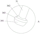
Fig. 3 is a schematic structural view of a portion a in fig. 2.
Fig. 4 is a schematic structural view of the turntable and the liquid storage tank in embodiment 2 of the present invention.
Fig. 5 is a schematic structural view of a portion B in fig. 4.
Fig. 6 is a schematic structural diagram of a turntable according to embodiment 2 of the present invention.
Fig. 7 is a schematic structural view of a liquid storage tank in embodiment 3 of the present invention.
Fig. 8 is a schematic structural view of embodiment 4 of the present invention.
Detailed Description
In order to make the objects, technical solutions and advantages of the present invention more clearly understood, the present invention is further described in detail below with reference to the accompanying drawings and embodiments. It should be understood that the specific embodiments described herein are merely illustrative of the invention and are not intended to limit the invention.
Based on the embodiments in the present invention, all other embodiments obtained by a person skilled in the art without creative efforts belong to the protection scope of the present invention.
In the description of the present invention, "plurality" means at least two, such as two, three, etc., unless specifically limited otherwise.
In addition, the technical solutions between the embodiments of the present invention can be combined with each other, but it is necessary to be able to be realized by a person having ordinary skill in the art as a basis, and when the technical solutions are contradictory or cannot be realized, the combination of such technical solutions should be considered to be absent, and is not within the protection scope of the present invention.
Example 1
Referring to fig. 1-3, an embodiment of the present invention provides a supporting structure for supporting plants in a liquid culture medium, including a liquid storage tank 1, a plurality of partition plates 11 are disposed in parallel on the upper side of the liquid storage tank 1, and the liquid storage tank 1 is partitioned into a plurality of cultivation troughs 12 by the partition plates 11, each cultivation trough 12 is provided with a cultivation box 2 adapted to the width of the corresponding cultivation trough 12, each cultivation box 2 is uniformly provided with a plurality of through holes 21 around the same height, one side of the liquid storage tank is provided with a liquid inlet 101, the other side is provided with a liquid outlet 102, the height of each through hole 21 is smaller than the height of the liquid inlet 101, and is larger than the height of the liquid outlet 102; the upside of every cultivation case 2 all is provided with planting hole 23, and the upside of every cultivation case 2 all is provided with around planting hole 23 connected support frame 3.
In this embodiment, according to the size of liquid reserve tank, can separate into 2 or 2 above cultivation grooves with the liquid reserve tank with the division board, can place a plurality of cultivation casees on every cultivation groove, conveniently adjust the interval between every 2 cultivation casees to the required interval space of adaptation different vegetation.
The left and right sides of liquid storage tank is provided with inlet and liquid outlet respectively, and the height that highly is greater than the liquid outlet of inlet, and every cultivation case sets up the through-hole more than 2 in the week side of same height, and the height of this through-hole is between the height of inlet, the height of liquid outlet.
When the liquid amount is added to the liquid storage tank, the liquid level of the liquid storage tank is higher than the through holes on the peripheral side of the cultivation box, so that the liquid flows into the cultivation box from the through holes, when the liquid in the liquid storage tank is discharged, the redundant liquid in the cultivation box flows out from the through holes, the liquid level in the cultivation box is kept at the required height, and the required liquid culture medium is conveniently supplemented for the cultivation box.
The support frame that is used for supporting the vegetation needs is all increased to the upside of every cultivation case, avoids the plant to take place the danger of slope or rupture stem in the growth process. The support structure is simple in overall structure, convenient to use, economical, environment-friendly and suitable for popularization and application.
The effect of support frame mainly is the growth that supports the plant, it is required in order to make the high adaptation plant of support frame grow, support frame 3 is including around planting a plurality of telescopic links 31 that 23 set up and set up in the connecting piece 32 of telescopic link 31 upside, the one end of every telescopic link 31 all is rather than the last side wall spherical hinge of the cultivation case 2 that corresponds, evenly be provided with U type groove 33 on the lateral wall of connecting piece 32, the other end of telescopic link 31 is pegged graft in U type groove 33, and can dismantle with U type groove 33 and be connected.
The telescopic link can stretch out and draw back the regulation, conveniently makes the height of support frame adjust along with vegetation to the better stem of supporting the plant. The shape of connecting piece is the ring shape, surrounds the stem of plant, conveniently provides the support. One end of the telescopic rod is hinged with the upper side wall of the cultivation box in a spherical shape, and the other end of the telescopic rod is hinged with the U-shaped groove in the outer side wall of the connecting piece, so that the telescopic rod can be conveniently adjusted along with the growth of plants. And the support frame can also properly correct the growth form of the plants. Here, the quantity of telescopic link is not restricted to 4, can be 3, 4, 5 or more than 5, mainly with the plant growth needs of reality select, under the condition that need not too many telescopic links, can freely dismantle, it is comparatively convenient to use.
Specifically, one end of the telescopic rod 31 is provided with a spherical hinge 34, the spherical hinge 34 comprises a ball seat 341, a hinge ball 342 and a ball cover 343, the ball seat 341 is in threaded connection with the ball cover 343 and is combined to form a cavity for accommodating the hinge ball 342, the hinge ball 342 is arranged in the cavity, the ball cover 343 is provided with a ball cover hole, one end of the telescopic rod 31 penetrates through the ball cover hole and is connected with the hinge ball 342, and the ball seat 341 is fixedly connected to one side of the planting hole 23; the setting of spherical articulated elements is more favorable to the adjustment of support frame, and it is more convenient to use, also convenient the dismantlement simultaneously.
The connecting member 32 includes a first connecting member 321, a second connecting member 322, and a torsion spring 323 connecting the first connecting member 321 and the second connecting member 322, wherein one end of the first connecting member 321 is hinged to one end of the second connecting member 322 through the torsion spring 323, and the other end of the first connecting member 321 is connected to the other end of the second connecting member 322. The first connecting piece and the second connecting piece are connected through the torsion spring, so that the connecting pieces can be reset through the torsion of the torsion spring, the stems of the plants can be conveniently sleeved into the connecting pieces to support the plants, and the other ends of the first connecting piece and the second connecting piece are always connected due to the torsion of the torsion spring.
In order to facilitate the movement of the cultivation box, the two sides of each cultivation box 2 are provided with the sliding blocks 24, the two sides of each cultivation groove 12 are provided with the limiting sliding grooves 13 matched with the sliding blocks 24, the sliding blocks on the two sides of the cultivation box can move along the limiting sliding grooves, the upper side of each sliding block 24 is connected with the handle 29, and the cultivation box is convenient to transfer and shift.
In order to conveniently clean the cultivation box, the cultivation box 2 comprises a cultivation box body 25 and a planting plate 26 positioned on the upper side of the cultivation box body 25, limiting blocks 27 used for supporting the planting plate 26 are arranged on two side walls inside the cultivation box body 25, and the planting plate is arranged on 2 limiting blocks; the planting holes 23 are arranged in the middle of the planting plate 26, and conical gauze bags 28 are arranged on the lower sides of the planting holes 23. In this embodiment, the cultivation case comprises cultivation case body and planting board, and during the clearance, only need to plant the board and take out, can clear up easy operation convenience to cultivation case body and planting board respectively. The gauze bag at the lower part of the planting hole is mainly used for separating roots and stems when plants grow conveniently and also is convenient for bearing a matrix required by planting.
Example 2
Referring to fig. 4-6, the difference from the above embodiment is that a rotary disc 4 is disposed on the upper side of the liquid storage tank 1, a plurality of first connection rings 41 are disposed on the lower side of the rotary disc 4, a vertical plate 14 perpendicular to the partition plate 11 is disposed on the upper side of each partition plate 11, a plurality of second connection rings 15 are disposed on both sides of each vertical plate 14, a rope winder 16 is disposed on one side of each second connection ring 15, and the connection ropes in the rope winder 16 are sequentially connected with the corresponding second connection rings 15 and the corresponding first connection rings 41, so as to facilitate the growth of the vine climbing plant. The cord winder may be used to adjust the length of the connection cord between the first connection ring and the second connection ring.
In order to further adjust the length of the connecting rope between the first connecting ring and the second connecting ring to adapt to the growth of the vine climbing plant, a first bevel gear 42 is arranged on the upper side of the rotating disc 4 and connected with the first bevel gear 42 through a rotating shaft, a second bevel gear 43 perpendicular to the first bevel gear 42 is arranged on one side of the first bevel gear 42 and meshed with the second bevel gear 43, a connecting rod 44 is arranged on one side of the second bevel gear 43, a roller shutter 45 is arranged on one side, away from the second bevel gear 43, of the connecting rod 44, and a roller shutter pulling ball 46 is arranged on the roller shutter 45. In this embodiment, draw the pearl through the pulling roll curtain, make the roll curtain ware rotate, make the connecting rod drive the rotation of second bevel gear, and first bevel gear and second bevel gear profile of tooth meshing to drive first bevel gear and rotate, make the carousel rotate, in order to adjust the length of the connecting rope between first go-between ring and the second go-between, in order to adapt to the growth of climbing rattan plant required.
In order to avoid insect damage to plants in the liquid storage tank, the insect prevention net cover 5 is arranged on the outer side of the rotary disc 4, and the lower end of the insect prevention net cover 5 is connected with the liquid storage tank 1, so that the growth environment of the plants in the whole liquid storage tank is isolated from the external environment, and the invasion of pests is avoided; the downside of carousel 4 is provided with light 47, provides illumination for the plant of cultivation in the stock solution pond through the light to make the plant also can carry out photosynthesis at night, promote vegetation, increase of production.
Example 3
Referring to fig. 7, the difference from the above embodiment is that the two ends of the liquid storage tank 1 are respectively provided with a lead screw 6 parallel to the partition plate 11, one side of each lead screw 6 is provided with a servo motor 7, the driving wheel of each servo motor 7 is connected with the driven wheel of the corresponding lead screw 6 through a synchronous belt, each lead screw 6 is provided with a lead screw nut 61 adapted to the lead screw 6, and each lead screw nut 61 is provided with a spin nozzle 62.
In this embodiment, one side of lead screw is provided with the slide bar parallel with the lead screw, and the one end of spin shower nozzle is passed through connection structure and slide bar connection, conveniently fixes a position spin shower nozzle, avoids spin shower nozzle to take place to rotate along with screw nut removes the in-process, and connection structure's one end is articulated with spin shower nozzle, and the other end is provided with the lantern ring, and with slide bar sliding connection, connection structure can be flexible adjustable pole, conveniently adjusts the water spray angle of spin shower nozzle.
The servo motor is started, the driving wheel of the servo motor rotates, and the driven wheel of the lead screw is driven to rotate through the synchronous belt, so that the lead screw is driven to rotate. Be provided with the external screw thread on the lead screw, lead screw nut inboard is provided with the internal thread with this external screw thread looks adaptation, makes lead screw nut remove to the right side from the left side along with the rotation of lead screw, conveniently makes the spin shower nozzle on the lead screw nut remove to the right side from the left side along with lead screw nut, makes the sprinkling irrigation begin from the left side, stops when removing to the right side. The moving speed of the self-rotating spray head is controlled by controlling the rotating speed of the servo motor, so that the spray irrigation is uniform. At the moment, the self-spinning spray head is fixed on the upper side of the screw nut and forms an included angle with the horizontal plane, the included angle is 30-60 degrees, and the self-spinning spray head needs to be externally connected with a water pipe in the using process.
Example 4
Referring to fig. 8, the difference from the above embodiment is that a graduated scale 17 is disposed on the side wall of the liquid storage tank 1, a liquid distribution tank 8 is disposed on the upper side of the liquid storage tank 1, a recovery tank 9 is disposed on the lower side of the liquid storage tank 1, a water pump 10 is disposed on one side of the recovery tank 9, the water pump 10 is respectively connected to the recovery tank 9 and the liquid distribution tank 8 through connecting pipes, a liquid inlet pipe 18 and a liquid outlet pipe 19 are respectively connected to the two sides of the liquid storage tank 1, one end of the liquid inlet pipe 18 is connected to a liquid inlet 101, the other end is connected to the liquid distribution tank 8 through a connecting pipe, one end of the liquid outlet pipe 19 is connected to a.
In this embodiment, the height that highly is greater than the drain pipe of feed liquor pipe, and be connected with the inlet of liquid storage tank, liquid outlet respectively, the inflow and the outflow of liquid in the convenient control liquid storage tank can set up the check valve on feed liquor pipe and the drain pipe of liquid storage tank both sides, the one-way flow of liquid in convenient control feed liquor pipe and the drain pipe.
The liquid depth in the liquid storage tank can be visually observed by the graduated scale in the liquid storage tank, so that the liquid level can be conveniently adjusted. Join in marriage highly being higher than the liquid reserve tank of cistern, make the nutrient solution of joining in marriage in the cistern be in the automatic liquid reserve tank that flows in by the feed liquor pipe after joining in marriage, and the height of liquid reserve tank is higher than the accumulator, can make the liquid in the accumulator by the automatic liquid reserve tank that flows of drain pipe, and shift the nutrient solution of accumulator to joining in marriage in the cistern through the water pump, the backward flow process of nutrient solution has been formed, realize circulation flow, not only can supply the nutrient solution of consumption in the liquid reserve tank at any time, can also make the oxygen content of nutrient solution in the in-process increase liquid that constantly flows, promote the growth of plant. The liquid level difference is utilized to carry out circulating flow, so that the energy consumption is reduced, and the energy-saving and environment-friendly effects are achieved.
The above description is only exemplary of the present invention and should not be construed as limiting the present invention, and any modifications, equivalents and improvements made within the spirit and principles of the present invention are intended to be included within the scope of the present invention.
Claims (10)
1. A support structure for supporting plants in a liquid culture medium comprises a liquid storage tank (1) and is characterized in that a plurality of partition plates (11) are arranged in parallel on the upper side of the liquid storage tank (1), the liquid storage tank is divided into a plurality of cultivation tanks (12) through the partition plates (11), each cultivation tank (12) is provided with a cultivation box (2) matched with the width of the corresponding cultivation tank (12), a plurality of through holes (21) are uniformly formed in the periphery of each cultivation box (2) at the same height, one side of the liquid storage tank (1) is provided with a liquid inlet (101), the other side of the liquid storage tank is provided with a liquid outlet (102), and the height of each through hole (21) is smaller than that of the liquid inlet (101) and larger than that of the liquid outlet (102); every the upside of cultivation case (2) all is provided with planting hole (23), every the upside of cultivation case (2) all is provided with around support frame (3) that planting hole (23) are connected.
2. The support structure for supporting plants in a liquid culture medium according to claim 1, wherein the support frame (3) comprises a plurality of telescopic rods (31) arranged around the planting holes (23) and a connecting piece (32) arranged at the upper side of each telescopic rod (31), one end of each telescopic rod (31) is spherically hinged with the upper side wall of the corresponding cultivation box (2), a U-shaped groove (33) is arranged on the outer side wall of each connecting piece (32), and the other end of each telescopic rod (31) is inserted into the U-shaped groove (33) and detachably connected with the U-shaped groove (33).
3. The supporting structure for supporting plants in a liquid culture medium according to claim 2, wherein a spherical hinge (34) is provided at one end of the telescopic rod (31), the spherical hinge (34) comprises a ball seat (341), a hinged ball (342) and a ball cover (343), the ball seat (341) is screwed with the ball cover (343) and combined to form a cavity for accommodating the hinged ball (342), the hinged ball (342) is provided in the cavity, a ball cover hole is provided on the ball cover (343), one end of the telescopic rod (31) passes through the ball cover hole and is connected with the hinged ball (342), and the ball seat (341) is fixedly connected to one side of the planting hole (23);
connecting piece (32) including first connecting piece (321), second connecting piece (322) and connection torsional spring (323) of first connecting piece (321) and second connecting piece (322), the one end of first connecting piece (321) with the one end of second connecting piece (322) is passed through torsional spring (323) and is articulated, the other end of first connecting piece (321) with the other end of second connecting piece (322) meets.
4. A support structure for supporting plants in a liquid culture medium according to claim 1, wherein two sides of each cultivation box (2) are provided with sliding blocks (24), two sides of each cultivation groove (12) are provided with limiting sliding grooves (13) matched with the sliding blocks (24), and the upper side of each sliding block (24) is connected with a handle (29).
5. The support structure for supporting plants in liquid culture medium according to claim 1, wherein the cultivation box (2) comprises a cultivation box body (25) and a planting plate (26) positioned at the upper side of the cultivation box body (25), and two side walls in the cultivation box body (25) are provided with limiting blocks (27) for supporting the planting plate (26); the planting holes (23) are formed in the middle of the planting plate (26), and conical gauze bags (28) are arranged on the lower sides of the planting holes (23).
6. The supporting structure for supporting plants in liquid culture medium according to claim 1, wherein the upper side of the liquid storage tank (1) is provided with a rotary disc (4), the lower side of the rotary disc (4) is provided with a plurality of first connecting rings (41), the upper side of each partition plate (11) is provided with a vertical plate (14) perpendicular to the partition plate (11), two sides of each vertical plate (14) are provided with a plurality of second connecting rings (15), one side of each second connecting ring (15) is provided with a rope winder (16), and the connecting ropes in the rope winder (16) are respectively connected with the corresponding second connecting rings (15) and the corresponding first connecting rings (41) in sequence.
7. The support structure for supporting plants in a liquid culture medium according to claim 6, wherein a first bevel gear (42) is arranged on the upper side of the rotary plate (4) and is connected with the first bevel gear (42) through a rotary shaft, a second bevel gear (43) perpendicular to the first bevel gear (42) is arranged on one side of the first bevel gear (42) and is meshed with the second bevel gear (43), a connecting rod (44) is arranged on one side of the second bevel gear (43), a roller blind device (45) is arranged on one side of the connecting rod (44) far away from the second bevel gear (43), and a roller blind pulling bead (46) is arranged on the roller blind device (45).
8. The supporting structure for supporting plants in liquid culture medium according to claim 6, wherein the outer side of the rotating disc (4) is provided with an insect screen (5), and the lower end of the insect screen (5) is connected with the liquid storage tank (1); and an illuminating lamp (47) is arranged on the lower side of the rotary disc (4).
9. The support structure for supporting plants in a liquid culture medium according to claim 1, wherein two ends of the liquid storage tank (1) are respectively provided with a lead screw (6) parallel to the partition plate (11), one side of each lead screw (6) is provided with a servo motor (7), a driving wheel of each servo motor (7) is connected with a driven wheel of the corresponding lead screw (6) through a synchronous belt, each lead screw (6) is provided with a lead screw nut (61) matched with the lead screw (6), and each lead screw nut (61) is provided with a spinning nozzle (62).
10. A support structure for supporting a plant in a liquid culture medium according to claim 1, a graduated scale (17) is arranged on the side wall of the liquid storage tank (1), a liquid distribution tank (8) is arranged on the upper side of the liquid storage tank (1), a recovery tank (9) is arranged at the lower side of the liquid storage tank (1), a water pump (10) is arranged at one side of the recovery tank (9), the water pump (10) is respectively connected with the recovery tank (9) and the liquid preparation tank (8) through connecting pipes, the two sides of the liquid storage tank (1) are respectively connected with a liquid inlet pipe (18) and a liquid outlet pipe (19), one end of the liquid inlet pipe (18) is connected with the liquid inlet (101), the other end is connected with the liquid preparation tank (8) through a connecting pipe, the liquid outlet pipe (19) is connected with the liquid outlet (102), and the other end of the liquid outlet pipe is connected with the recovery tank (9) through a connecting pipe.
Priority Applications (1)
| Application Number | Priority Date | Filing Date | Title |
|---|---|---|---|
| CN201920894608.1U CN210076230U (en) | 2019-06-13 | 2019-06-13 | Support structure for supporting plants in liquid culture medium |
Applications Claiming Priority (1)
| Application Number | Priority Date | Filing Date | Title |
|---|---|---|---|
| CN201920894608.1U CN210076230U (en) | 2019-06-13 | 2019-06-13 | Support structure for supporting plants in liquid culture medium |
Publications (1)
| Publication Number | Publication Date |
|---|---|
| CN210076230U true CN210076230U (en) | 2020-02-18 |
Family
ID=69482863
Family Applications (1)
| Application Number | Title | Priority Date | Filing Date |
|---|---|---|---|
| CN201920894608.1U Expired - Fee Related CN210076230U (en) | 2019-06-13 | 2019-06-13 | Support structure for supporting plants in liquid culture medium |
Country Status (1)
| Country | Link |
|---|---|
| CN (1) | CN210076230U (en) |
Cited By (2)
| Publication number | Priority date | Publication date | Assignee | Title |
|---|---|---|---|---|
| CN111587779A (en) * | 2020-05-29 | 2020-08-28 | 宁夏大学 | Stem and fruit plant nutrient solution cultivation device |
| CN113197082A (en) * | 2021-05-20 | 2021-08-03 | 盐城中农国业农业科技股份有限公司 | Plant factory plants equipment |
-
2019
- 2019-06-13 CN CN201920894608.1U patent/CN210076230U/en not_active Expired - Fee Related
Cited By (2)
| Publication number | Priority date | Publication date | Assignee | Title |
|---|---|---|---|---|
| CN111587779A (en) * | 2020-05-29 | 2020-08-28 | 宁夏大学 | Stem and fruit plant nutrient solution cultivation device |
| CN113197082A (en) * | 2021-05-20 | 2021-08-03 | 盐城中农国业农业科技股份有限公司 | Plant factory plants equipment |
Similar Documents
| Publication | Publication Date | Title |
|---|---|---|
| CN104855262B (en) | The cultivation implantation methods of organic Herba Dendrobii | |
| CN104686142A (en) | Aeroponic virus-free seed potato breeding method and accessory equipment | |
| CN210076230U (en) | Support structure for supporting plants in liquid culture medium | |
| CN107969339B (en) | Anoectochilus roxburghii cultivation method | |
| CN206212912U (en) | Rotary plant cultivation apparatus without soil | |
| CN111894181B (en) | Green building curtain wall | |
| CN111466231A (en) | Can make up rotatory flowerpot of viewing and admiring of gear drive formula that multiple plant planted | |
| CN109169219B (en) | Method for soilless culture of strawberries | |
| CN210840805U (en) | Intelligent greenhouse is with cultivation device | |
| CN205052416U (en) | There is not native plant planter | |
| CN116806676A (en) | Soilless culture seedling device | |
| CN217790609U (en) | Dedicated device of growing seedlings is planted to chrysanthemum | |
| CN212367989U (en) | Equipment is cultivateed with plant in gardens | |
| CN111661894B (en) | Ecological purifier of sewage that water planting plant intelligence was bred | |
| CN211064352U (en) | Seedling raising device for controlling root growth of hickory | |
| CN210120855U (en) | Spherical fish-vegetable symbiotic three-dimensional device | |
| CN111903390A (en) | Equipment is cultivateed with plant in gardens | |
| CN204518762U (en) | Ring type water fog cultivating device assembly | |
| CN111819980A (en) | Large-range hydrangea planting irrigation system | |
| CN207340715U (en) | A kind of multilayer automatic-watering planting unit | |
| CN220476437U (en) | Breeding case is used in crops breeding | |
| CN218184282U (en) | Nursery stock artificial containers convenient to adjust | |
| CN112136557B (en) | Agricultural cultivation device and using method thereof | |
| CN219330185U (en) | Novel rice incubator | |
| CN219421931U (en) | Garden type ecological cycle device |
Legal Events
| Date | Code | Title | Description |
|---|---|---|---|
| GR01 | Patent grant | ||
| GR01 | Patent grant | ||
| CF01 | Termination of patent right due to non-payment of annual fee |
Granted publication date: 20200218 Termination date: 20210613 |
|
| CF01 | Termination of patent right due to non-payment of annual fee |