CN203599023U - Stationary-line oven - Google Patents
Stationary-line oven Download PDFInfo
- Publication number
- CN203599023U CN203599023U CN201320694841.8U CN201320694841U CN203599023U CN 203599023 U CN203599023 U CN 203599023U CN 201320694841 U CN201320694841 U CN 201320694841U CN 203599023 U CN203599023 U CN 203599023U
- Authority
- CN
- China
- Prior art keywords
- tool
- arm
- baking box
- line
- guide rail
- Prior art date
- Legal status (The legal status is an assumption and is not a legal conclusion. Google has not performed a legal analysis and makes no representation as to the accuracy of the status listed.)
- Expired - Fee Related
Links
Images

Classifications
-
- F—MECHANICAL ENGINEERING; LIGHTING; HEATING; WEAPONS; BLASTING
- F27—FURNACES; KILNS; OVENS; RETORTS
- F27D—DETAILS OR ACCESSORIES OF FURNACES, KILNS, OVENS, OR RETORTS, IN SO FAR AS THEY ARE OF KINDS OCCURRING IN MORE THAN ONE KIND OF FURNACE
- F27D3/00—Charging; Discharging; Manipulation of charge
- F27D3/06—Charging or discharging machines on travelling carriages
-
- B—PERFORMING OPERATIONS; TRANSPORTING
- B25—HAND TOOLS; PORTABLE POWER-DRIVEN TOOLS; MANIPULATORS
- B25J—MANIPULATORS; CHAMBERS PROVIDED WITH MANIPULATION DEVICES
- B25J15/00—Gripping heads and other end effectors
- B25J15/06—Gripping heads and other end effectors with vacuum or magnetic holding means
- B25J15/0616—Gripping heads and other end effectors with vacuum or magnetic holding means with vacuum
-
- B—PERFORMING OPERATIONS; TRANSPORTING
- B25—HAND TOOLS; PORTABLE POWER-DRIVEN TOOLS; MANIPULATORS
- B25J—MANIPULATORS; CHAMBERS PROVIDED WITH MANIPULATION DEVICES
- B25J9/00—Programme-controlled manipulators
- B25J9/0084—Programme-controlled manipulators comprising a plurality of manipulators
-
- B—PERFORMING OPERATIONS; TRANSPORTING
- B25—HAND TOOLS; PORTABLE POWER-DRIVEN TOOLS; MANIPULATORS
- B25J—MANIPULATORS; CHAMBERS PROVIDED WITH MANIPULATION DEVICES
- B25J9/00—Programme-controlled manipulators
- B25J9/0093—Programme-controlled manipulators co-operating with conveyor means
-
- B—PERFORMING OPERATIONS; TRANSPORTING
- B25—HAND TOOLS; PORTABLE POWER-DRIVEN TOOLS; MANIPULATORS
- B25J—MANIPULATORS; CHAMBERS PROVIDED WITH MANIPULATION DEVICES
- B25J9/00—Programme-controlled manipulators
- B25J9/02—Programme-controlled manipulators characterised by movement of the arms, e.g. cartesian coordinate type
- B25J9/023—Cartesian coordinate type
-
- F—MECHANICAL ENGINEERING; LIGHTING; HEATING; WEAPONS; BLASTING
- F27—FURNACES; KILNS; OVENS; RETORTS
- F27B—FURNACES, KILNS, OVENS, OR RETORTS IN GENERAL; OPEN SINTERING OR LIKE APPARATUS
- F27B9/00—Furnaces through which the charge is moved mechanically, e.g. of tunnel type; Similar furnaces in which the charge moves by gravity
- F27B9/14—Furnaces through which the charge is moved mechanically, e.g. of tunnel type; Similar furnaces in which the charge moves by gravity characterised by the path of the charge during treatment; characterised by the means by which the charge is moved during treatment
- F27B9/20—Furnaces through which the charge is moved mechanically, e.g. of tunnel type; Similar furnaces in which the charge moves by gravity characterised by the path of the charge during treatment; characterised by the means by which the charge is moved during treatment the charge moving in a substantially straight path tunnel furnace
- F27B9/24—Furnaces through which the charge is moved mechanically, e.g. of tunnel type; Similar furnaces in which the charge moves by gravity characterised by the path of the charge during treatment; characterised by the means by which the charge is moved during treatment the charge moving in a substantially straight path tunnel furnace being carried by a conveyor
Landscapes
- Engineering & Computer Science (AREA)
- Mechanical Engineering (AREA)
- Robotics (AREA)
- General Engineering & Computer Science (AREA)
- Automatic Assembly (AREA)
- Specific Conveyance Elements (AREA)
Abstract
The utility model relates to a stationary-line oven. The stationary-line oven comprises a lifting device, a conveying line, a product grabbing mechanism, a plurality of fixtures and a fixture grabbing mechanism, wherein the conveying line is arranged on one side of the stationary-line oven, the product grabbing mechanism is arranged at the top end of the other side of the stationary-line oven, and the fixture grabbing mechanism is located below the product grabbing mechanism. The product grabbing mechanism comprises a first guide rail, a supporting arm and manipulators, wherein the supporting arm is arranged on the first guide rail and can slide along the first guide rail, the manipulators are connected with the supporting arm and used for grabbing or releasing products, each fixture comprises a fixture groove, and the fixture grooves are used for containing products. The fixture grabbing mechanism comprises a second guide rail and a fixture clamping mechanism, the fixture clamping mechanism is arranged on the second guide rail and can slide along the second guide rail, and the fixture clamping mechanism is used for grabbing or releasing the fixtures so as to achieve press fitting or disassembly of the fixtures.
Description
Technical field
The utility model relates to a kind of glue curing baking box, relates in particular to a kind of standing line baking box for solidified glue.
Background technology
In industrial production, often need to carry out baking and curing processing to glue that is coated on product surface etc., traditional glue curing mode is to adopt streamline baking box, this type of baking box needs manually product to be put into tool, and position, subsequently tool is carried out to pressing processing, put into conveyer line and make product introduction baking box carry out baking and curing processing, after having solidified, still need manually to disassemble tool and product is taken out.Whole process needs a large amount of manual operations, and the quality of product is unstable, and working (machining) efficiency is low, and such baking box is bulky in addition, internal heat skewness, and power consumption is high, and heat consume is serious, and capacity usage ratio is low.
Utility model content
In view of this, be necessary to provide a kind of automatic discharging, feeding and auto-stitching, disassemble the standing line baking box of the small size of tool.
A kind of line baking box that leaves standstill, comprises lowering or hoisting gear and is installed in the conveyer line that leaves standstill line baking box one side, also comprises and is installed in the tool grasping mechanism that leaves standstill product grasping mechanism, multiple tool of line baking box opposite side apical position and be positioned at product grasping mechanism below.Product grasping mechanism comprises the first guide rail, is installed on the first guide rail and the support arm that can slide along the first rail and the manipulator being connected with described support arm, and manipulator is for capturing or release products.Tool comprises the tool groove for accommodating product.Tool grasping mechanism comprises the second guide rail and is installed in also can be along the tool clamping device of this second guide rail slip on the second guide rail, and tool clamping device is for capturing or discharging tool with pressing or disassemble tool.
Preferably, described support arm is " Z " shape, comprises principal arm and two side arms that are positioned at principal arm both sides.
Preferably, described manipulator comprises arm and handgrip, and this arm is connected with the side arm of support arm, and described arm can be along moving up and down perpendicular to this side arm direction, and this handgrip is connected in described arm one end.
Preferably, described handgrip is provided with the vacuum generator in order to draw or to place product.
Preferably, described tool clamping device comprises two slide blocks and is arranged at two flat boards between slide block, on this flat board, offers groove, offers direction offer hollow-out parts perpendicular to groove, is provided with transmission tong in this hollow-out parts.
Preferably, described tool clamping device also comprises rhombus frame, and this rhombus frame four edges is the rigid structure that length is identical, and four summits are by rivet stitching that can be movable, and four edges can relatively move.
Preferably, on the each sidewall of described tool groove, at least comprise a guide pad, described guide pad is inclined-plane near the one side of tool groove, and each guide pad cooperatively interacts, and when product is put into, just slips into tool groove, and be positioned in tool groove along inclined-plane.
Preferably, described tool also comprises the pressing post being positioned on tool and is arranged at the lug boss in tool two opposite side walls, described pressing post inside comprises clamp button of the spring, clamp button of the spring is pressed while moving inward and can be opening at lug boss, and clamp button of the spring is lock-out state in the time that lug boss is resumed original state.
Preferably, described lowering or hoisting gear is arranged at tool grasping mechanism both sides, comprises the first lifting arm, the second lifting arm and the first lifting platform being connected with the first lifting arm, the second lifting platform being connected with the second lifting arm.
Preferably, described conveyer line comprises tool for stitching conveyer line, tool conveyer line to be disassembled and discharging conveyer line, described tool for stitching conveyer line with described in tool conveyer line to be disassembled be set in parallel in and leave standstill one end of line baking box, described discharging conveyer line is positioned at tool conveyer line to be disassembled top.
The volume of standing line baking box of the present utility model is little, can realize auto-stitching or disassemble tool by tool grasping mechanism, coordinate product grasping mechanism product is put into tool or take out from tool simultaneously, this process is without manual operation, the product processing is stable, can effectively save human cost, enhance productivity.
Accompanying drawing explanation
Fig. 1 is the schematic perspective view that the utility model preferred embodiment leaves standstill line baking box.
Fig. 2 is the top view of the standing line baking box shown in Fig. 1.
Fig. 3 is the schematic perspective view of the product grasping mechanism of the standing line baking box shown in Fig. 1.
Fig. 4 is the schematic perspective view of the tool grasping mechanism of the standing line baking box shown in Fig. 1.
Fig. 5 is the schematic perspective view of the tool of the standing line baking box shown in Fig. 1.
Main element symbol description
| Leave standstill |
100 |
| |
10 |
| |
20 |
| |
30 |
| Lowering or hoisting |
40 |
| Conveyer |
50 |
| The first guide rail | 11 |
| Support arm | 12 |
| Principal arm | 121 |
| The first side arm | 122 |
| The second side arm | 123 |
| The first manipulator | 13 |
| The second manipulator | 14 |
| |
21 |
| |
22 |
| |
23 |
| Lug |
24 |
| The second guide rail | 31 |
| Tool clamping device | 32 |
| Dull and stereotyped | 322 |
| Groove | 3221 |
| Hollow-out parts | 3222 |
| Rhombus frame | 323 |
| Transmission tong | 325 |
| The |
41 |
| The |
43 |
| The |
42 |
| The |
44 |
| Tool for |
51 |
| Tool conveyer line to be disassembled | 52 |
| Discharging |
53 |
The following specific embodiment further illustrates the utility model in connection with above-mentioned accompanying drawing.
The specific embodiment
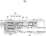
Referring to Fig. 1 and Fig. 2, the utility model preferably embodiment provides a kind of line baking box 100 that leaves standstill, for the drying adhesive on product 101 surfaces is solidified.In the present embodiment, leave standstill line baking box 100 and comprise product grasping mechanism 10, tool 20, tool grasping mechanism 30, lowering or hoisting gear 40 and conveyer line 50.Product grasping mechanism 10 is positioned at the top that leaves standstill line baking box 100 1 sides, tool grasping mechanism 30 is positioned at product grasping mechanism 10 belows, in order to clamping fixture 20, lowering or hoisting gear 40 is positioned at the below of tool grasping mechanism 30, and conveyer line 50 is longitudinally arranged on and leaves standstill in line baking box 100.
Please refer to Fig. 3, product grasping mechanism 10 comprises the first guide rail 11, support arm 12, the first manipulator 13 and the second manipulator 14.
The first guide rail 11 is fixed at and leaves standstill on line baking box 100.
Support arm 12 is installed in the first guide rail 11 tops slidably, and in the present embodiment, support arm 12 is " Z " shape, can slide along the first guide rail 11.Support arm 12 comprises principal arm 121 and lays respectively at the first side arm 122 and second side arm 123 of principal arm 121 both sides.
The first manipulator 13 is installed on the first side arm 122 slidably, the first handgrip 132 that it comprises the first arm 131 and is connected with the first arm 131, the first arm 131 is connected with the first side arm 122, and the first arm 131 can be along moving up and down perpendicular to the first side arm 122 directions.The quantity that is respectively equipped with multiple the first vacuum generator 133, the first vacuum generators 133 on the first handgrip 132 can be determined according to the object that will clamp.By the first vacuum generator 133 and product 101 Surface Contacts and the inner vacuum that produces, product 101 is picked up, when the inner air amount of the first vacuum generator 133, after vacuum expendable pattern, product 101 can be put down.
The structure of the second manipulator 14 structures and the first manipulator 13 is roughly the same, comprises the second arm 141 of being connected with the second side arm 123, is connected in second handgrip 142 of second arm 141 one end and is arranged at the second vacuum generator 143 on the second handgrip 142.
When support arm 12 slides to first guide rail 11 one end, the first manipulator 13 captures processed product 101, the second manipulator 14 captures the product 101 having toasted, in the time that support arm 12 slides to first guide rail 11 other end, the first manipulator 13 is put into sky tool 20, the second manipulators 14 by processed product 101 product having toasted 101 is positioned on conveyer line 50.
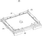
Please refer to Fig. 4, tool 20 comprises tool groove 21, and tool groove 21 is roughly rectangular, comprises four sidewalls and the groove between sidewall, for accommodating and positioning product 101.The each sidewall of tool groove 21 top is at least provided with a guide pad 22, and guide pad 22 is inclined-plane near the one side of tool groove 21, and each guide pad 22 cooperatively interacts, and when product 101 is put into, just slips into tool groove 21, and be positioned in tool groove 21 along inclined-plane.
On 20 liang of relative sidewalls of tool, be respectively equipped with lug boss 24, be pressed while moving inward at lug boss 24, the clamp button of the spring of pressing post 23 inside is opening, and two tools 20 of stack now can be disassembled separation up and down; Lug boss 24 be cancelled exert pressure restore to the original state time, the clamp button of the spring of pressing post 23 inside is lock-out state, up and down stack two tools 20 locked by pressing.Tool 20 can recycle in standing line baking box 100, without taking-up.
Refer to Fig. 2 and Fig. 5, this tool grasping mechanism 30 comprises the second guide rail 31 and tool clamping device 32.
The second guide rail 31 comprises two slideways, and two slideways are set in parallel in the first guide rail 11 belows, and correspond respectively to the two ends of the first guide rail 11, and the bearing of trend of the second guide rail 31 is substantially vertical with the bearing of trend of the first guide rail 11.
Tool clamping device 32 comprises two slide blocks 321, at the flat board 322 between two slide blocks 321 and be arranged at the rhombus frame 323 on dull and stereotyped 322 centers.Two slide blocks 321 are arranged in respectively on two slideways of the second guide rail 31, and can slide along the second guide rail 31, and dull and stereotyped 322 two ends are connected with two slide blocks 321 respectively.On dull and stereotyped 322, offer groove 3221, dull and stereotyped 322 also offer hollow-out parts 3222 offering perpendicular to groove 3221 in direction.Rhombus frame 323 four edges are isometric rigid structure, and four summits are by rivet stitching, but nail is not dead, four edges can relatively move, and rivet stitching place forms respectively 3231, the second joint portions 3232, the first joint portion, the 3rd 3233, the four joint portions 3234, joint portion.
Tool clamping device 32 also comprise be arranged at groove 3221 inside two groove follower 324, be arranged at two transmission tongs 325 of hollow-out parts 3222 inside and be arranged at the cylinder 326 on dull and stereotyped 322.Two groove follower 324 are connected with the first joint portion 3231, the 3rd joint portion 3233 respectively, make the first joint portion 3231 and the 3rd joint portion 3233 only along groove 3221 simultaneously near or move away from dull and stereotyped 322 centers.One end of two transmission tongs 325 is connected with the second joint portion 3232 and the 4th joint portion 3234 respectively, make two transmission tongs 325 can be simultaneously near or move away from dull and stereotyped 322 centers, the other end of two transmission tongs 325 coordinates can clamping fixture 20.Cylinder 326 can drive transmission tong 325 to move, in the time that two transmission tongs 325 move to close dull and stereotyped 322 centers simultaneously, two transmission tongs 325 can clamping fixture 20, and transmission tong 325 is when moving away from dull and stereotyped 322 centers, and two transmission tongs 325 unclamp tool 20.
Continue referring to Fig. 1 and Fig. 2, lowering or hoisting gear 40 comprises the first lifting arm 41, the second lifting arm 42, the first lifting platform 43 being connected with the first lifting arm 41, and the second lifting platform 44 being connected with the second lifting arm 42.The first lifting arm 41 and the second lifting arm 42 lay respectively at the second guide rail 31 both sides, the first lifting arm 41 and the second lifting arm 42 except can fast lifting, simultaneously can also be as required the distance of tool 20 thickness of lifting successively.The first lifting platform 43 and the second lifting platform 44 are positioned at the second guide rail 31 belows, and the first lifting platform 43 is placed pending tool 20, and for the pressing of tool, the second lifting platform 44 is placed the tool 20 having toasted, for disassembling of tool.
Conveyer line 50 comprises tool for stitching conveyer line 51, tool conveyer line 52 to be disassembled and discharging conveyer line 53.Tool for stitching conveyer line 51 is set in parallel in tool conveyer line 52 to be disassembled the one end that leaves standstill line baking box 100, tool for stitching conveyer line 51 by pressing complete but not baking whole folded tool 20 send into inner baking box (not shown), tool conveyer line 52 to be disassembled by baking complete whole folded tool 20 to be disassembled deliver to the second lifting platform 44.Discharging conveyer line 53 is positioned at tool conveyer line to be disassembled 52 tops, and the product machining 101 is delivered to discharging opening.
When being installed, this standing line baking box 100 can carry out in accordance with the following steps: first, product grasping mechanism 10 is arranged on and leaves standstill line baking box 100 1 side tops, tool grasping mechanism 30 is arranged on product grasping mechanism 10 belows, the first lifting arm 41 and the second lifting arm 42 are installed on respectively tool grasping mechanism 30 both sides, the first lifting platform 43 is connected with the first lifting arm 41 and the second lifting arm 42 respectively with the second lifting platform 44, and is arranged at the second guide rail 31 belows.Conveyer line 50 is arranged at and leaves standstill line baking box 100 opposite sides, and tool for stitching conveyer line 51 is set in parallel in and leaves standstill line baking box 100 1 side lower parts with tool conveyer line 52 to be disassembled, and discharging conveyer line 53 is positioned at tool conveyer line to be disassembled 52 tops.In the time that the first lifting platform 43 drops to extreme lower position, engage with tool for stitching conveyer line 51, in the time that the second lifting platform 44 drops to extreme lower position, engage with tool conveyer line 52 to be disassembled.
Further illustrate the utility model and leave standstill the operation principle of line baking box 100 below in conjunction with Fig. 1 and Fig. 2: first, tool clamping device 32 carries sky tool 20 and slides into the first lifting platform 43 tops, the rise distance of a tool thickness of the first lifting arm 41, pressing post 23 upper and lower sleeves that make on the first lifting platform 43 the empty tool 20 that the pressing post 23 of the tool 20 of placing carries with tool clamping device 32 with together with, transmission tong 325 unclamps sky tool 20, lug boss 24 loses chucking power effect, restore to the original state, the clamp button of the spring of pressing post 23 inside of empty tool 20 is lock-out state, empty tool 20 pressings are secured on the whole folded tool on the first lifting platform 43.
When tool clamping device 32 carries sky tool 20 and slides into the first lifting platform 43 top, the rise distance of a tool thickness of the second lifting arm 42, support arm 12 slides into first guide rail 11 one end, now the first manipulator 13 is positioned at charging aperture position, and the second manipulator 14 is positioned at the second lifting platform 44 tops.For sake of convenience, defining the now residing position of support arm 12 is initial position.Subsequently, the first arm 131 is along moving down perpendicular to the first side arm 122 directions, capture processed product 101, after completing, crawl is moved upward to origin-location, the second arm 141 is along moving down perpendicular to the second side arm 123 directions simultaneously, capture the product having toasted 101 on the second lifting platform 44, after having captured, be moved upward to origin-location.
Then, tool clamping device 32 slides to the second lifting platform 44 tops, the decline distance of a tool thickness of the first lifting arm 41.Transmission tong 325 clamps empty tool 20, inwardly press lug boss 24 at chucking power effect underdrive tong 325, lug boss 24 moves inward, the clamp button of the spring of pressing post 23 inside is opening, the decline distance of a tool thickness of the second lifting arm 42, the empty tool 20 being held dismantles from whole folded tool.
When tool clamping device 32 slides into the second lifting platform 44 top, support arm 12 slides into first guide rail 11 other ends, and now the first manipulator 13 is positioned at the first lifting platform 43 tops, and the second manipulator 14 is positioned at directly over discharging conveyer line 53.On the first lifting platform 43, be placed with sky tool 20, the first arm 131 moves down puts into sky tool 20 by processed product 101, processed product 101 slips into tool groove 21 and is positioned along the guide pad 22 of tool 20, after placement completes, the first arm 131 is moved upward to origin-location, simultaneously the second arm 141 moves down converted products 101 is placed on discharging conveyer line 53, after having placed, is moved upward to origin-location.
Then, tool clamping device 32 carries sky tool 20 and again slides into the first lifting platform 43 tops, and support arm 12 slides into initial position again, so repeats.
After on the second lifting platform 44, whole folded tool 20 is taken, the first lifting platform 43 just drops to its extreme lower position, engage with tool for stitching conveyer line 51, whole folded tool is delivered on tool for stitching conveyer line 51, subsequently, the first lifting platform 43 rises to rapidly the extreme higher position of its setting, the second lifting platform 44 is dropped rapidly to its extreme lower position simultaneously, engage with tool conveyer line 52 to be disassembled, tool 20 to be disassembled is sent on the second lifting platform 44, after feeding, the second lifting platform 44 rises to desired location, make tool clamping device 32 can just clamp the uppermost a slice tool 20 of whole folded tool, so start the processing of new one folded product 101.
Above-mentioned standing line baking box 100 is provided with product grasping mechanism 10, below product grasping mechanism 10, be provided with tool grasping mechanism 30, and be provided with apparatus for automatically lifting 40 in tool grasping mechanism 30 both sides, leave standstill line baking box 100 by tool grasping mechanism 30 auto-stitchings or disassemble tool 20, and coordinate product grasping mechanism 10 product is put into tool 20 or take out from tool 20, this process is without manual operation, the product processing is stable, can effectively save human cost, enhance productivity, and the standing line baking box small volume of this structure.
Claims (10)
1. a standing line baking box, comprise lowering or hoisting gear and be installed in the conveyer line that leaves standstill line baking box one side, it is characterized in that: described standing line baking box also comprises the product grasping mechanism that is installed in standing line baking box opposite side apical position, multiple tools and be positioned at the tool grasping mechanism of product grasping mechanism below, this product grasping mechanism comprises the first guide rail, the support arm that is installed on the first guide rail and can slide along the first rail and the manipulator being connected with described support arm, this manipulator is for capturing or release products, this tool comprises the tool groove for accommodating product, this tool grasping mechanism comprises the second guide rail and is installed on the second guide rail and the tool clamping device that can slide along this second guide rail, this tool clamping device is for capturing or discharging tool with pressing or disassemble tool.
2. standing line baking box as claimed in claim 1, is characterized in that: described support arm is " Z " shape, comprises principal arm and two side arms that are positioned at principal arm both sides.
3. standing line baking box as claimed in claim 1, is characterized in that: described manipulator comprises arm and handgrip, and this arm is connected with the side arm of support arm, and described arm can be along moving up and down perpendicular to this side arm direction, and this handgrip is connected in described arm one end.
4. standing line baking box as claimed in claim 3, is characterized in that: described handgrip is provided with the vacuum generator in order to draw or to place product.
5. standing line baking box as claimed in claim 1, it is characterized in that: described tool clamping device comprises two slide blocks and is arranged at two flat boards between slide block, on this flat board, offer groove, offer in direction and offer hollow-out parts perpendicular to this groove, in this hollow-out parts, be provided with transmission tong.
6. standing line baking box as claimed in claim 5, is characterized in that: described tool clamping device also comprises rhombus frame, this rhombus frame four edges is the rigid structure that length is identical, and four summits are by rivet stitching that can be movable, and four edges can relatively move.
7. standing line baking box as claimed in claim 1, it is characterized in that: on the each sidewall of described tool groove, at least comprise a guide pad, described guide pad is inclined-plane near the one side of tool groove, each guide pad cooperatively interacts, when product is put into, just slip into tool groove along inclined-plane, and be positioned in tool groove.
8. standing line baking box as claimed in claim 1, it is characterized in that: this tool also comprises the pressing post being positioned on this tool and is arranged at the lug boss in this tool two opposite side walls, described pressing post inside comprises clamp button of the spring, this clamp button of the spring is pressed while moving inward and can be opening at this lug boss, and this clamp button of the spring is lock-out state in the time that this lug boss is resumed original state.
9. standing line baking box as claimed in claim 1, it is characterized in that: described lowering or hoisting gear is arranged at tool grasping mechanism both sides, comprise the first lifting arm, the second lifting arm and the first lifting platform being connected with the first lifting arm, the second lifting platform being connected with the second lifting arm.
10. standing line baking box as claimed in claim 1, it is characterized in that: described conveyer line comprises tool for stitching conveyer line, tool conveyer line to be disassembled and discharging conveyer line, described tool for stitching conveyer line with described in tool conveyer line to be disassembled be set in parallel in and leave standstill one end of line baking box, described discharging conveyer line is positioned at tool conveyer line to be disassembled top.
Priority Applications (2)
| Application Number | Priority Date | Filing Date | Title |
|---|---|---|---|
| CN201320694841.8U CN203599023U (en) | 2013-11-06 | 2013-11-06 | Stationary-line oven |
| US14/517,326 US9476647B2 (en) | 2013-11-06 | 2014-10-17 | Production line oven |
Applications Claiming Priority (1)
| Application Number | Priority Date | Filing Date | Title |
|---|---|---|---|
| CN201320694841.8U CN203599023U (en) | 2013-11-06 | 2013-11-06 | Stationary-line oven |
Publications (1)
| Publication Number | Publication Date |
|---|---|
| CN203599023U true CN203599023U (en) | 2014-05-21 |
Family
ID=50711724
Family Applications (1)
| Application Number | Title | Priority Date | Filing Date |
|---|---|---|---|
| CN201320694841.8U Expired - Fee Related CN203599023U (en) | 2013-11-06 | 2013-11-06 | Stationary-line oven |
Country Status (2)
| Country | Link |
|---|---|
| US (1) | US9476647B2 (en) |
| CN (1) | CN203599023U (en) |
Cited By (2)
| Publication number | Priority date | Publication date | Assignee | Title |
|---|---|---|---|---|
| CN109013240A (en) * | 2016-03-23 | 2018-12-18 | 肖剑 | A kind of ceramic product mobile heating unit |
| CN112607414A (en) * | 2020-12-18 | 2021-04-06 | 深圳市聚亿鑫电子科技有限公司 | Tear open and plant trigger |
Families Citing this family (5)
| Publication number | Priority date | Publication date | Assignee | Title |
|---|---|---|---|---|
| US10233027B1 (en) | 2016-06-03 | 2019-03-19 | Zme, Llc | Material handling apparatus and method |
| US9745137B1 (en) | 2016-06-03 | 2017-08-29 | Zme, Llc | Apparatus, system and method for material handling and/or processing |
| CN106003687A (en) * | 2016-06-15 | 2016-10-12 | 温州职业技术学院 | Clamping and lifting mechanism of PTFE hollow pipe flanging forming equipment |
| US11122810B2 (en) | 2016-08-25 | 2021-09-21 | Zme, Llc | Material processing system |
| CN110220370B (en) * | 2019-06-26 | 2023-11-17 | 东莞市德瑞精密设备有限公司 | Goods shelf type lithium battery baking equipment |
Family Cites Families (4)
| Publication number | Priority date | Publication date | Assignee | Title |
|---|---|---|---|---|
| JP3571471B2 (en) * | 1996-09-03 | 2004-09-29 | 東京エレクトロン株式会社 | Processing method, coating and developing processing system and processing system |
| DE102009033697A1 (en) * | 2009-07-17 | 2011-01-27 | Knapp Ag | Method and storage system for storing and picking articles |
| BR112012015640B1 (en) * | 2009-12-21 | 2020-09-29 | Wilfried Strothmann Gmbh Maschinenbau Und Handhabungstechnik | HANDLING ELEMENT |
| JP5717503B2 (en) * | 2011-03-30 | 2015-05-13 | 富士重工業株式会社 | Press product inspection equipment |
-
2013
- 2013-11-06 CN CN201320694841.8U patent/CN203599023U/en not_active Expired - Fee Related
-
2014
- 2014-10-17 US US14/517,326 patent/US9476647B2/en active Active
Cited By (3)
| Publication number | Priority date | Publication date | Assignee | Title |
|---|---|---|---|---|
| CN109013240A (en) * | 2016-03-23 | 2018-12-18 | 肖剑 | A kind of ceramic product mobile heating unit |
| CN109013240B (en) * | 2016-03-23 | 2021-12-03 | 乐清市泰博恒电子科技有限公司 | Portable heating device is used to ceramic product |
| CN112607414A (en) * | 2020-12-18 | 2021-04-06 | 深圳市聚亿鑫电子科技有限公司 | Tear open and plant trigger |
Also Published As
| Publication number | Publication date |
|---|---|
| US20150125237A1 (en) | 2015-05-07 |
| US9476647B2 (en) | 2016-10-25 |
Similar Documents
| Publication | Publication Date | Title |
|---|---|---|
| CN203599023U (en) | Stationary-line oven | |
| CN207459099U (en) | A kind of Full-automatic battery cell package machine | |
| WO2022021959A1 (en) | Multi-station fixing, clamping and automatic stamping apparatus based on multi-axis industrial robot | |
| CN207282630U (en) | Power battery is from dynamic circuit connector core glue plastering machine | |
| CN207451079U (en) | A kind of automatic charging blanking equipment of service plate | |
| CN204584852U (en) | Materials device fetched and delivered by a kind of manipulator | |
| CN107244551A (en) | A kind of rotary type circuit board captures robot automatically | |
| CN110039310B (en) | Full-automatic shell assembling machine | |
| CN107622912B (en) | A kind of relay spring kludge | |
| CN105436979B (en) | A kind of equidistantly sub-material intermediate station | |
| CN205237504U (en) | Automatic assembly equipment of motor | |
| CN105775732A (en) | Automatic grabbing machine convenient to move | |
| CN104044008A (en) | Workpiece transfer device | |
| CN107826722B (en) | Automatic feeding machine | |
| CN108857311B (en) | Hot melting disassembly equipment for paint spraying jig plate | |
| CN106734712B (en) | A kind of can system processed | |
| CN205571214U (en) | Unloader in stamping equipment's automation | |
| CN212120865U (en) | Automatic production device for reinforcing plate | |
| CN210451962U (en) | Automatic material pouring equipment | |
| CN209357848U (en) | A kind of secondary localization machine of battery core based on CCD | |
| CN210059449U (en) | Independent stamping manipulator | |
| CN209380764U (en) | Glass tube conveying robot | |
| CN110883160A (en) | Automatic stamping equipment for cylinder sleeve | |
| CN104176314B (en) | collecting device of remote controller | |
| CN217636775U (en) | Sheet conveying machine of vertical diffusion furnace |
Legal Events
| Date | Code | Title | Description |
|---|---|---|---|
| C14 | Grant of patent or utility model | ||
| GR01 | Patent grant | ||
| CF01 | Termination of patent right due to non-payment of annual fee |
Granted publication date: 20140521 Termination date: 20151106 |
|
| EXPY | Termination of patent right or utility model |